Loading ...
Loading ...
Loading ...
petsafe.com 29
System Test
The system test is used to determine the cause of system problems that have not been
addressed elsewhere in this guide. You will need a piece of boundary wire greater than
15 ft. long with
3
⁄
8
in. of insulation removed from each end to use as a test loop wire. Make
a note of your boundary width dial setting, and receiver collar setting before beginning the
system test.
Follow the steps below to perform the system test:
1. Remove the receiver collar from your dog and make sure it is fully charged.
2. Set the boundary control switch to B.
3. Set the receiver collar static correction to level 5.
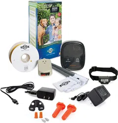
4. Disconnect the twisted boundary wire from the boundary wire terminals on the fence
transmitter by pressing the red release levers on the connector and pulling the wires
free (13A).
5. Insert the two ends of the test loop wire into the boundary wire terminals
on the transmitter.
6. Turn the boundary width control knob to 10 and then back to 5.
7. Place the test light tool contacts on the contact points of the receiver collar. While
holding the receiver collar with the test light tool in place, approach the wire from the
outside loop 2 inches off the ground. Make a mental note of the distance where the
receiver collar activates from the wire.
8. Turn the boundary width control knob to 10 and repeat step 7. The distance where the
receiver collar activates should be greater than the previous result.
9. If more than one receiver collar is used on the system, repeat the above test
on each collar.
10. Keep the boundary width control knob position at 10. Set the boundary control switch
to A. Then approach the loop with the receiver collar, as in step 7, and verify that the
receiver collar activates.
11. Keep the boundary width control knob position at 10. This time set the boundary control
switch to C. Approach the loop with the receiver collar, as in step 7, and verify that the
receiver collar activates.
12. Interpreting the results:
a. If the power light or the loop indicator light are not both lit on the fence transmitter,
or the alarm is on, for any of the above tests, there is a problem with the transmitter.
Contact the Customer Care Center.
b. If both the power and loop indicator lights are on, but the receiver collar does
not activate on the test loop wire, the receiver collar is not working. Contact the
Customer Care Center.
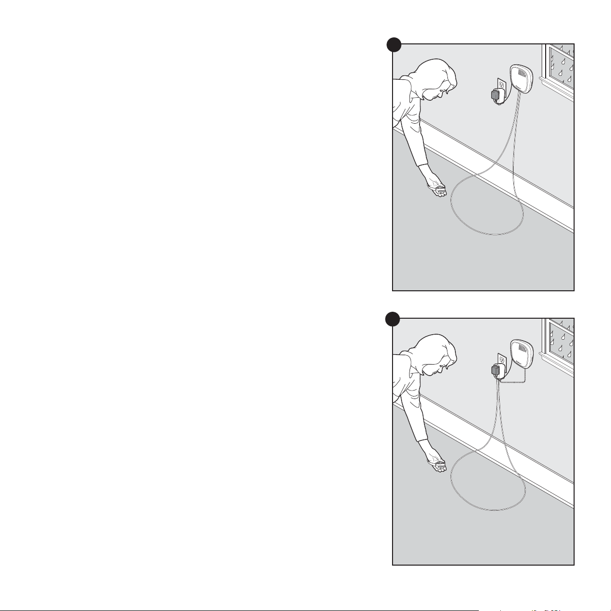
c. If the transmitter power and loop indicator lights are on in each of the 3 boundary
control switch positions and the receiver collar is activating at different distances on
the test loop wire, the problem is most likely in the containment boundary wire or surge
protector. Reconnect the transmitter wires to the surge protector and connect the test
loop to the surge protector loop terminals (13B). Repeat steps 6–11.
System Test Surge Protector
Connected
System Test Surge Protector
Unconnected
13B
13A
Loading ...
Loading ...
Loading ...