
Loading ...
Loading ...
Loading ...
Connecting External Monitors and Recording Devices
112
External Devices Connection
To display recording/playback pictures on an
external monitor, select the output signal and use
an appropriate cable for the monitor to be
connected.
An output signal from the camcorder can be
recorded when a recording device is connected.
The same status information and menus can be
displayed on the external monitor as those on the
viewfinder screen.
According to the signal fed to the monitor, set
“Output Display” (page 90) in the Video menu to
“On.”
SDI OUT connector (BNC type)
Set the on/off setting of the output, and output
format in the Video menu (page 88).
Use a commercially available 75-ohm coaxial
cable for connection.
Note
Be sure to ground between the camcorder and external
device before turning the power on. (We recommend to
turn on the camcorder and external device after
connecting a 75-ohm coaxial cable.)
When connecting an external device to the camcorder
while the camcorder is turned on, connect the external
device after connecting a 75-ohm coaxial cable to the
external device.
To start synchronized recording on an external
device
With SDI signal output selected, synchronized
recording is possible by feeding a REC trigger
signal to an external recording device connected
via the SDI OUT connector. To enable
synchronized recording, set “SDI Rec Control”
(page 98) in the Recording menu to “HD SDI
Remote I/F” or “Parallel Rec.”
Notes
• When a connected external device does not correspond
to a REC trigger signal, the device cannot be operated.
• “HD SDI Remote I/F” is enabled when an external
device is connected to SDI OUT 1 to 4. “Parallel Rec”
is enabled when an external device is connected to only
SDI OUT 1/2.
HDMI OUT connector (Type A connector)
Set the on/off setting of the output, and output
format in the Video menu (page 88).
Use a commercially available HDMI cable for
connection.
TEST OUT connector (BNC type)
Use a commercially available BNC cable for
connection.
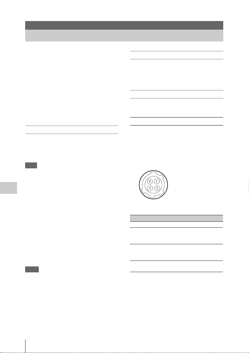
DC OUT connector (4-pin)
Supplies DC 12 V power to an accessory when
the power switch is set to ON.
You can output the REC Tally signal and input
the REC Trigger signal through the DC OUT
connector.
External Devices Connection
Connecting External Monitors and Recording Devices
No. Signal I/O Specification
1 UNREG GND – GND for UNREG
2 REC TALLY OUT Open Collector
output (Max. 50 mA)
Low: REC
3 REC TRIGGER IN Open or +5 V dc:
Normal
GND: Active (REC)
4 UNREG +12 V
OUT
OUT +11 V to 17 V dc
output
4-pin, Female
- External View -
Loading ...
Loading ...
Loading ...