Loading ...
Loading ...
Loading ...
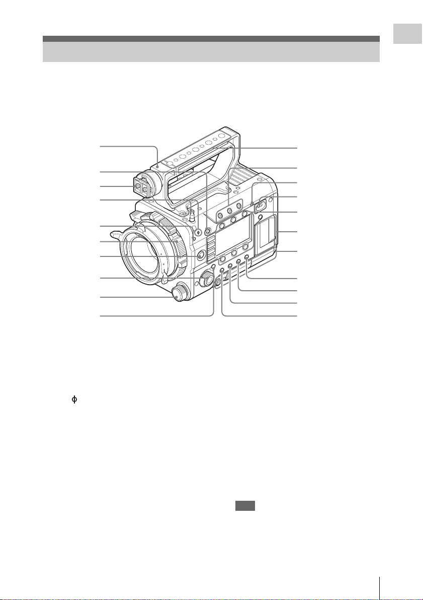
Location and Function of Parts
11
Overview
For functions and usage, see the pages in parentheses.
The following illustrations are with the battery adaptor (page 16) removed.
For removing the battery adaptor, see “Removing a battery pack” (page 23).
1. Handle
2. LOCK switch
Disables operations on the side operating panel.
3. Viewfinder shoe
4. Tape measure hook/Image sensor position
index
The mark and tape measure hook are on a
plane with the image sensor. To measure the
precise distance between the camcorder and the
subject, use this mark or tape measure hook as a
reference.
You can attach the end of a tape measure to the
hook, and measure the distance from the subject.
The tape measure hook can be attached to the
inside part or outside part of the camcorder.
5. Flange focal length adjustment screw
(page 26)
6. Lens mount (page 25)
7. REC (recording start/stop) button/lamp
(page 41)
8. SEL/SET (select/set) dial (MENU dial)
(pages 53, 58, 67)
Selects the item in the menu or changes the
setting value.
9. ND FILTER select switch
ND filters are available for keeping the
aperture in a proper range.
Select the ND filter by turning the ND
FILTER select switch while pulling it.
Clear: ND filter not used
0.9:
1
/
8
ND
1.8:
1
/
64
ND
10. CANCEL/BACK button (pages 53, 58, 67)
11. Accessory mounting screw holes
Type of screw: 1/4-20UNC (× 4)
Type of screw: 3/8-16UNC (× 5)
Length of engagement: 9 mm
(
3
/
8
inch) or less
Note
Do not apply excessive force to the mounted
accessory. It may damage the screw thread.
12. ASSIGN (assignable) 1/2/3 buttons (page
44)
Location and Function of Parts
1
3
4
6
2
5
10
7
8
9
11
12
13
15
16
17
18
14
Sub display/Control
buttons block (page 14)
SxS memory card slot
block (page 14)
Right side connector
panel (page 14)
Loading ...
Loading ...
Loading ...