Loading ...
Loading ...
Loading ...
unpacking
CONTENTS
UNPACKING AND CHECKING CONTENTS ..... 6
ASSEMBLY .................................... 7
Mounting Belt and Disc Sander On
Recommended Craftsman Floor Base ........ 7
Check Motor Rotation .......................... 11
On-Off Switch .............................. 13
Installing Work Table ....................... 15
Installing Abrasive Belt-Tensioning and Tracking 16
Installing Belt Dust Trap ..................... 17
Installing Backstop .............................. 18
GETTING TO KNOW YOUR SANDER ............ 18
Belt Adjusting Screws .......................... 19
Belt Locking Screws ......................... 19
Work Table Tilt Lock Screw .................... 19
Backstop Lock Screw ............................ 20
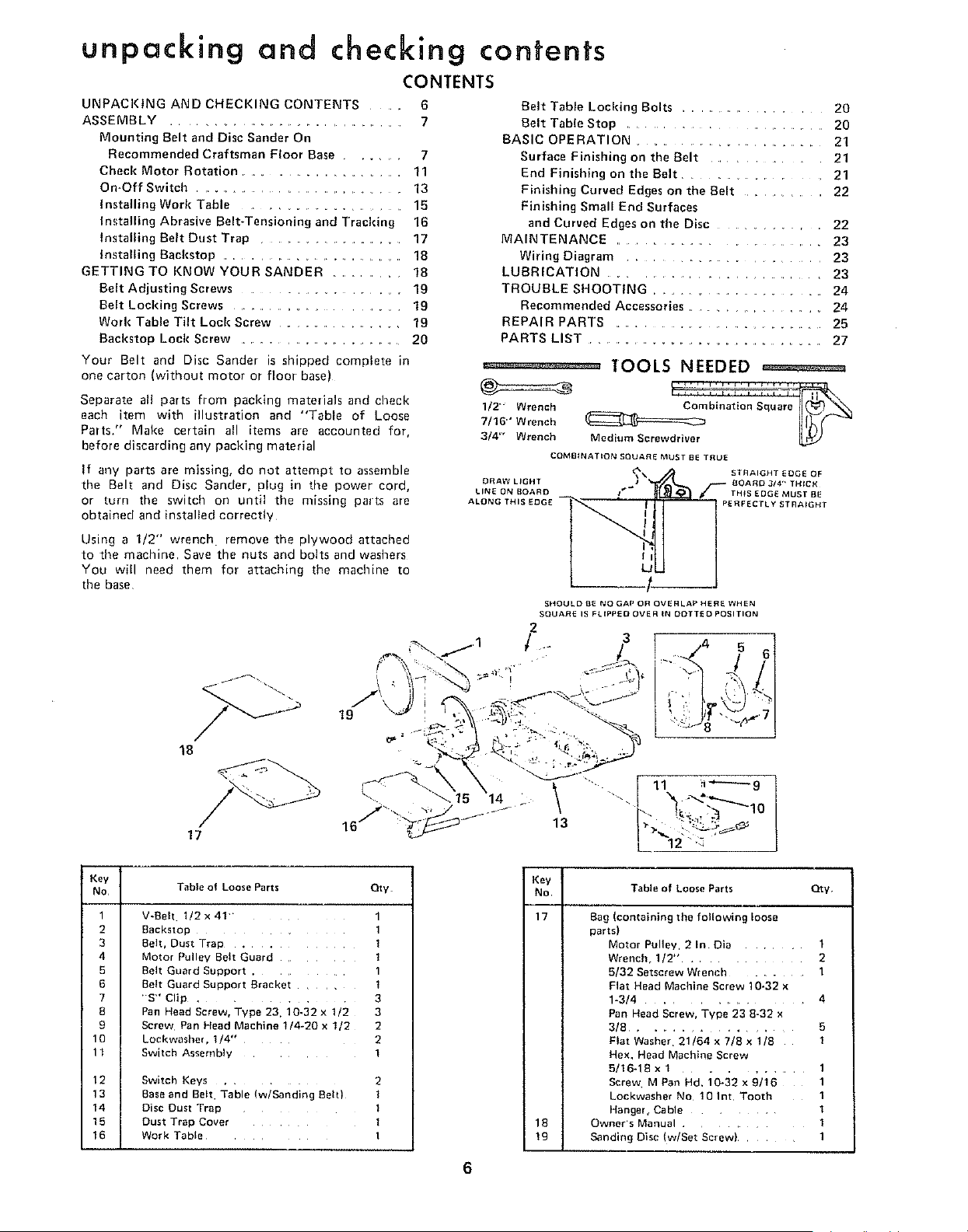
Your Belt and Disc Sander is shipped complete in
one carton (without motor or floor base)
Separate all parts from packing materials and check
each item with illustration and "Table of Loose
Parts." Make certain all items are accounted for,
before discarding any packing material
If any parts are missing, do not attempt to assemble
the Belt and Disc Sander, plug in time power cord,
or turn the switch on until the missing parts are
obtained and installed correctly
Using a 1/2" wrench• remove the plywood attached
to time machine Save the nuts and bolts and washers
You will need them for attaching the machine to
the base
19
18
and checking contents
Belt Table Locldng Bolts ....................... 20
Belt Table Stop ......................... 20
BASIC OPERATION ............................. 21
Surface Finishing on the Belt ................. 21
End Finishing on the Belt ................ 21
Finishing Curved Edges on the Belt .............. 22
Finishing Small End Surfaces
and Curved Edges on the Disc ............. 22
MAINTENANCE ......................... 23
Wiring Diagram ...................... 23
LUBRICATION ....................... 23
TROUBLE SHOOTING ............................ 24
Recommended Accessories ................. 24
REPAIR PARTS ................................. 25
PARTS LIST ..................................... 27
°_ _"_°_--° TOOLS NEEDED ==========
1/2"" Wrench __
W16"' Wrench
3/4' Wrench Medium Screwdriver
COMBINATION SQUARE MUST BE TRUE
DRAW LIGHT
LINE ON BOARD
ALONG THI
STRAIGHT EDGE OF
BOARD 3/4" TH{CK
TH_S EDGE MUST BE
PERFECTLY STRAIGHT
SHOULD BE NO GAP OR OVERLAP HERE WHEN
SQUARE IS FLIPPED OVER IN DOTTED POSITION
2
"r/ .. 3 5
17
\ ......111 1
14 Z ""-,
16/' " .......
L 2"'_
Key
No
1
2
3
4
5
6
7
8
9
10
11
12
13
14
15
16
Table o1 Loose Parts Oty
V-Beh 1/2x4!
Backstol: 1
Belt, Dust Trap . 1
Motor Pul ev Belt Guard ]
Belt Guard Suoport .
3elt Guard SUDDOrt Bracket
'S" Clip . 3
Pan Head Screw. Type 23. 10-32 x 1/2 3
Screw Pan Head Machine 1/4-20 x 1/2 2
LockwasheL 1/4- 2
Switch Assembly i
Switch Keys 2
Baseand Belt Table (w/Sanding Belt) I
Disc Dust TraD I
Dust Trap Cover l
Work Table I
Key
No
17
i
i
i IB
Table of Loose Farts Qty
Bag (containing the following loose
parts)
Motor Pulley, 2 In Din ........ 1
Wrench, 1I2" ............. 2
5/32 Setscrew Wrench ......... 1
Flat Head Machine Screw 10-32 x
1-3/4 ................. 4
Pan Head Screw, Type 23 8-32 x
3/8 ............... 5
Flat Washer 21/64 x 7/8 x 1/8 1
Hex. Head Machine Screw
5/16-18 x 1 ........... 1
Screw MPan Hd. 10-32x9/16 1
Lockwasher No 10 Int Tooth 1
Hange{, Cable ........ 1
Owner's Manual ............ 1
Sanding Disc (w/Set Screw) ........ 1
6
Loading ...
Loading ...
Loading ...