Loading ...
Loading ...
Loading ...
b) Connection to a Closed Loop System
Condenser Water
Supply Inlet
Minimum Condenser
Water Supply Line Size
Condenser
Return Outlet
Minimum Condenser
Return Line Size
1/2" Female Pipe
Thread (FPT)
1/4" Nominal ID Copper
Water Tubing or Equivalent
1/2" Female Pipe
Thread (FPT)
1/4" Nominal ID Copper
Water Tubing or Equivalent
• Shut-off valves and drain valves must be installed at both the condenser water supply inlet
and condenser return outlet.
• Minimum water ow to the condenser is 4 GPM.
• The pressure differential between the condenser water supply inlet and condenser return
outlet must be no less than 10 PSIG.
• When using a glycol blend, the solution mixture should be less than 30% glycol.
• In order to maintain the proper high side pressure, the condenser water supply inlet
temperature should not drop below 45°F (7°C) and the condenser drain outlet temperature
must be in the 104°F to 115°F (40°C to 46°C) range. Once the icemaker installation is
complete, conrm the condenser drain outlet temperature 5 minutes after a freeze cycle
starts. If the condenser drain outlet temperature is not in the proper range, use a at
blade screwdriver to rotate the adjustment screw on the water-regulating valve until the
temperature is in the proper range.
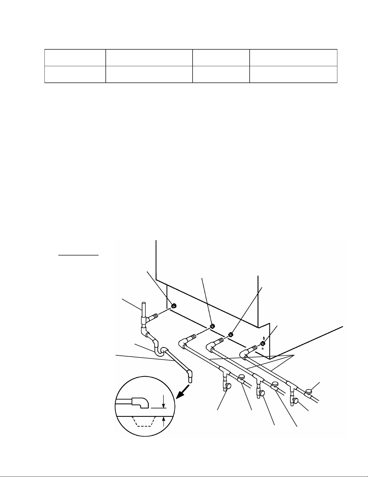
Fig. 6
KM-161BWJ
Icemaker Water Supply
Inlet 1/2” FPT
Icemaker Drain
Outlet 3/4” FPT
Condenser Return
Outlet 1/2” FPT
Condenser Water
Supply Inlet 1/2” FPT
To approved
oor drain
1/4” fall per foot
Shut-o Valve
Drain Valve
Minimum 1/4” Nominal ID
Copper Water Tubing or
Equivalent
Shut-o Valve
Drain Valve
Minimum 3/4” Nominal ID
Hard Pipe or Equivalent
Trap
Shut-O ValveDrain Valve
Be sure there is sucient
extra water supply line and
drain line for the appliance
to be pulled out for service.
Separate piping to approved
drain. Leave a 2-inch (5-cm)
vertical air gap between the
end of each pipe and the
drain.
2-inch (5-cm)
air gap
Drain
Floor
Vent Tube
19
Loading ...
Loading ...
Loading ...