
1
Book
V1.00E
The
2
Table of contents
1. Sensor & format ....................................................................................................................... 5
1-1. Super 35mm sized imager with 5.7K resolution.................................................................. 6
1-2. Active area ......................................................................................................................... 6
1-3. Record time ....................................................................................................................... 7
1-4. Applicable memory cards ................................................................................................... 8
2. Preparation before filming ........................................................................................................ 9
2-1. Terminals ......................................................................................................................... 10
2-2. Accessory and tripod mounting holes ............................................................................... 11
2-3. HOME screen .................................................................................................................. 12
2-3-1. COLOR sertings ....................................................................................................... 13
2-3-2. AUDIO setting .......................................................................................................... 14
2-3-3. INFO screen ............................................................................................................ 15
2-4. User assignable buttons .................................................................................................. 18
2-4-1. Assigning features .................................................................................................... 19
2-4-2. Assignable functions ................................................................................................ 20
2-4-3. Checking functions assigned to USER buttons ......................................................... 21
3. MENU settings ....................................................................................................................... 22
3-1. MENU items over view
..................................................................................................... 23
3-1-1. SYSTEM MODE ...................................................................................................... 24
3-1-2. COLOR SETTINGS ................................................................................................. 24
3-1-3. USER SWITCHES ................................................................................................... 25
3-1-4. SIDE LOCK .............................................................................................................. 25
3-1-5. LED & FAN .............................................................................................................. 26
3-1-6. LCD ......................................................................................................................... 26
3-1-7. CLOCK .................................................................................................................... 26
3-1-8. INFORMATION ........................................................................................................ 26
3-1-9. LANGUAGE ............................................................................................................. 27
3-1-10. INITIALIZE ............................................................................................................. 27
3-1-11. FPS ........................................................................................................................ 28
3-1-12. SHUTTER .............................................................................................................. 28
3-1-13. EI ........................................................................................................................... 29
3-1-14. WHITE ................................................................................................................... 30
3-1-15. NR ......................................................................................................................... 30
3-1-16. LENS SETTING ..................................................................................................... 30
3-1-17. IR SHOOTING ....................................................................................................... 30
3-1-18. E.I.S. ...................................................................................................................... 31
3-1-19. AUTO BLACK BALANCE ....................................................................................... 31
3-1-20. NAME EDIT ........................................................................................................... 32
3-1-21. SCENE DATA......................................................................................................... 32
3-1-22. BLACK ................................................................................................................... 32
3-1-23. GAMMA ................................................................................................................. 33
3-1-24. KNEE ..................................................................................................................... 34
3-1-25. KNEE Effect ........................................................................................................... 34
3-1-26. HLG KNEE ............................................................................................................. 35

3
3-1-27. WHITE CLIP .......................................................................................................... 35
3-1-28. DETAIL .................................................................................................................. 35
3-1-29. SKIN DETAIL ......................................................................................................... 35
3-1-30. CHROMA ............................................................................................................... 36
3-1-31. MATRIX ................................................................................................................. 36
3-1-32. COLOR CORRECTION ......................................................................................... 37
3-1-33. CARDS/MEDIA ...................................................................................................... 38
3-1-34. CLIP NAME ............................................................................................................ 38
3-1-35. 2 SLOTS FUNC. .................................................................................................... 38
3-1-36. PRE REC ............................................................................................................... 38
3-1-37. TC .......................................................................................................................... 38
3-1-38. AUDIO CH SETTINGS ........................................................................................... 40
3-1-39. AUDIO INPUT ........................................................................................................ 40
3-1-40. AUDIO OUTPUT .................................................................................................... 41
3-1-41. REC BEEP SOUND ............................................................................................... 41
3-1-42. ALARM................................................................................................................... 41
3-1-43. SDI OUT ................................................................................................................ 42
3-1-44. HDMI OUT ............................................................................................................. 43
3-1-45. SDI/HDMI INDICATOR ........................................................................................... 44
3-1-46. SDI/HDMI MARKER ............................................................................................... 44
3-1-47. LCD INDICATOR ................................................................................................... 45
3-1-48. LCD MARKER ....................................................................................................... 47
3-1-49. LCD FOCUS ASSIST ............................................................................................. 47
3-1-50. LCD EI ASSIST ...................................................................................................... 48
3-1-51. LCD LEVELGAUGE ............................................................................................... 49
3-1-52. COLOR BARS ....................................................................................................... 49
3-1-53. SCENE FILE .......................................................................................................... 50
3-1-54. SETUP FILE .......................................................................................................... 50
3-1-55. NETWORK SEL ..................................................................................................... 51
3-1-56. NETWORK FUNC .................................................................................................. 51
3-1-57. NETWORK PROPERTY ........................................................................................ 51
3-1-58. CONNECTION HISTORY ...................................................................................... 52
3-1-59. NETWORK TOOLS ................................................................................................ 52
3-1-60. AREA SETTINGS ................................................................................................... 53
4. Understanding advanced features ......................................................................................... 54
4-1. Understanding Variable Frame Rate (VFR) recording ...................................................... 55
4-2. Monitoring image and recording ....................................................................................... 56
4-3. Understanding focus assist modes .................................................................................. 57
4-4. Understanding sport meter as Exposure Index (EI) assist ................................................ 59
4-5. Understanding Electric Image Stabilizer (EIS) function .................................................... 61
4-6. Understanding dual memory card slot feature .................................................................. 62
4-7. Synchronize timecode ...................................................................................................... 63
4-8. Understanding remote operation via EVA ROP application............................................... 64

4
5. File format ............................................................................................................................... 67
5-1. Folder structure in the record media ................................................................................ 68
5-2. Folder name (MOV format) .............................................................................................. 69
5-3. File name (MOV format) .................................................................................................. 70
6. Appendix ................................................................................................................................. 71
6-1. Battery runtime ................................................................................................................ 72
6-2. Scene file preset .............................................................................................................. 73
6-3. Output signals (SDI and HDMI) ........................................................................................ 74
6-4. Error and warning system ................................................................................................ 77
6-5. Genuine accessories ....................................................................................................... 81
6-6. Specifications .................................................................................................................. 83
6-7. Dimensions ...................................................................................................................... 87
Revision history ...................................................................................................................... 88

5
1. Sensor & format
6
The AU-EVA1 is a cinema camera recorder, featuring a newly developed super 35mm sized
imager with 5.7K resolution, and can record in several formats and compression, offering up to
10-bit 4:2:2 even in 4K. The EVA1 contains V-Log/V-Gamut capture to deliver high dynamic range
and a broad color gamut.
1-1. Super 35mm sized imager with 5.7K resolution
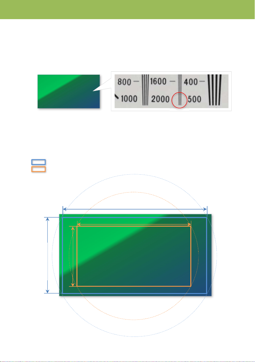
The new 17:9 imager (5720 x 3016 active pixels) achieves 2000 horizontal TV lines.
1-2. Active area
The EVA1 uses two different areas on its imager for capturing, depending on frame rate in variable
frame rate (VFR) record mode. The areas, called S35 and 4/3 areas can be changed with the
SENSOR MODE menu item.
MENU > SYSTEM SETTINGS > SENSOR MODE
S35 area (used for up to 120fps per second)
4/3 area (used for up to 240fps per second)
5720 x 3016
Active pixels
10.251
mm
19.436mm
1. Sensor & format
24.596mm
12.969
mm

7
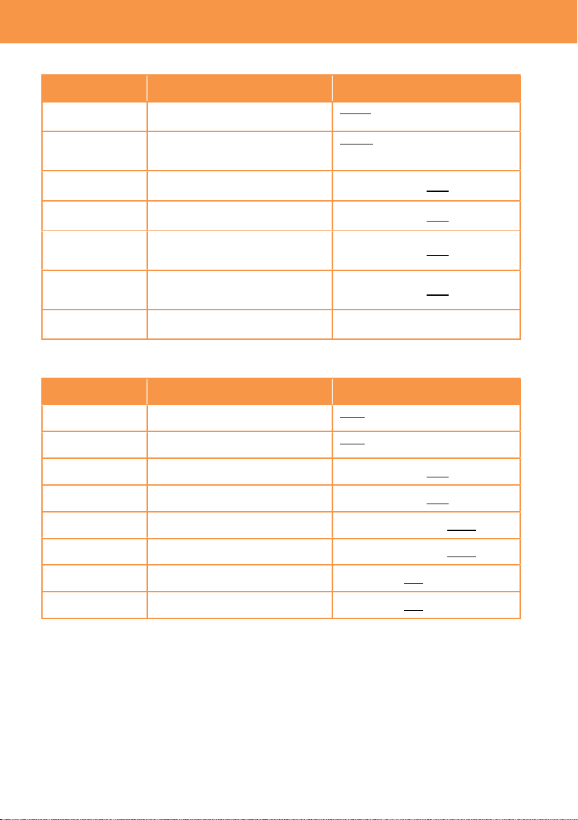
1-3. Record time
For
mat
Resolution
Main Codec Frame rate Sampling
Rec time
(128GB)
MOV
4096x2160
(4K)
422Intra 400M
29.97p, 24p, 25p,
23.98p
4:2:2 10bit 40m
422LongGOP150M
29.97p, 24p, 25p,
23.98p
4:2:2 10bit 1h50m
420LongGOP150M 59.94p, 50p 4:2:0 8bit 1h50m
420LongGOP100M
29.97p, 24p, 25p,
23.98p
4:2:0 8bit 2h40m
3840x2160
(UHD)
422Intra 400M 29.97p, 25p, 23.98p
4:2:2 10bit 40m
422LongGOP150M 29.97p, 25p, 23.98p 4:2:2 10bit 1h50m
420LongGOP150M 59.94p, 50p 4:2:0 8bit 1h50m
420LongGOP100M 29.97p, 25p, 23.98p 4:2:0 8bit 2h40m
2048x1080
(2K)
422Intra 200M 59.94p, 50p 4:2:2 10bit 1h20m
422Intra 100M
29.97p, 24p, 25p,
23.98p
4:2:2 10bit 2h40m
422LongGOP100M 59.94p, 50p 4:2:2 10bit 2h40m
422LongGOP50M
29.97p, 24p, 25p,
23.98p
4:2:2 10bit 5h20m
420LongGOP100M 59.94p, 50p 4:2:0 8bit 2h40m
420LongGOP50M
29.97p, 24p, 25p,
23.98p
4:2:0 8bit 5h20m
1920x1080
(FHD)
422Intra 200M 59.94p, 50p 4:2:2 10bit 1h20m
422Intra 100M 29.97p, 25p, 23.98p
4:2:2 10bit 2h40m
422LongGOP100M 59.94p, 50p 4:2:2 10bit 2h40m
422LongGOP50M 29.97p, 25p, 23.98p 4:2:2 10bit 5h20m
420LongGOP100M 59.94p, 50p 4:2:0 8bit 2h40m
420LongGOP50M 29.97p, 25p, 23.98p 4:2:0 8bit 5h20m
AVCHD
1920x1080
(FHD)
PS (Ave.25Mbps) 59.94p, 50p 4:2:0 8bit 11h
PH (Ave.21Mbps) 23.98p, 59.94i, 50i 4:2:0 8bit 12h30m
HA (Ave.17Mbps) 59.94i, 50i 4:2:0 8bit 17h
1280x720
(HD)
PM (Ave.8Mbps) 59.94p, 50p 4:2:0 8bit 35h
Record times are approx.
1. Sensor & format
(Bold: to be supported with firmware update)
8
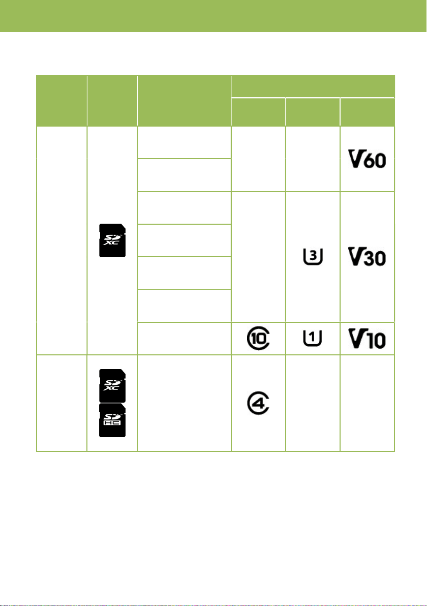
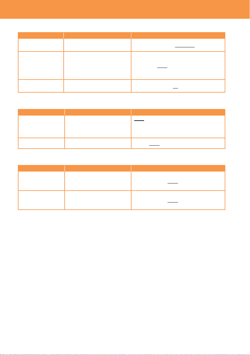
1-4. Applicable memory cards
Applicable type or speed class of SD memory card varies depends on record format and mode.
Format
SD
memory
card type
Record bit-rate,
record mode
Minimum requirement of speed class
Speed
class
UHS
speed class
Video
speed class
MOV
400Mbps
-- --
2K/FHD, VFR mode
(Intra codec)
200Mbps
--
150Mbps
100Mbps
2K/FHD, VFR mode
(Long-GOP codec)
50Mbps
AVCHD
PS, PH, HA, PM
-- --
1. Sensor & format

9
2. Preparation before
filming
10
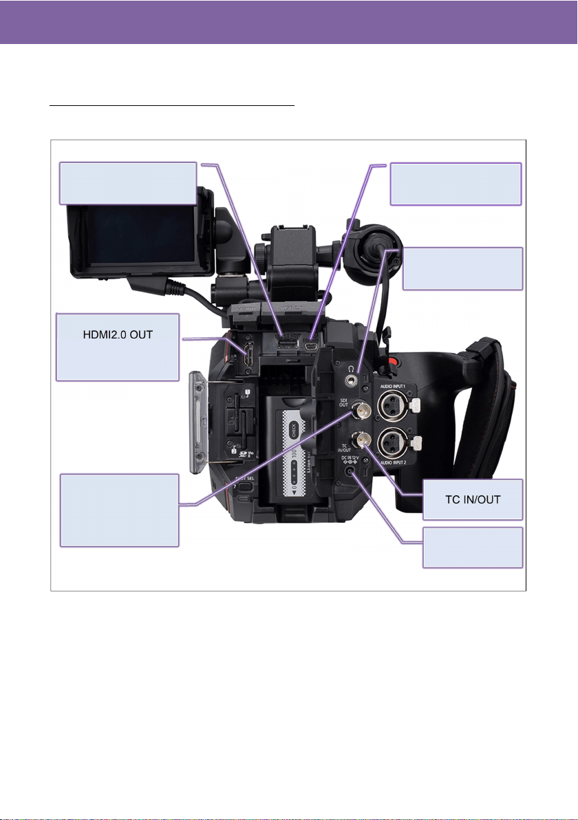
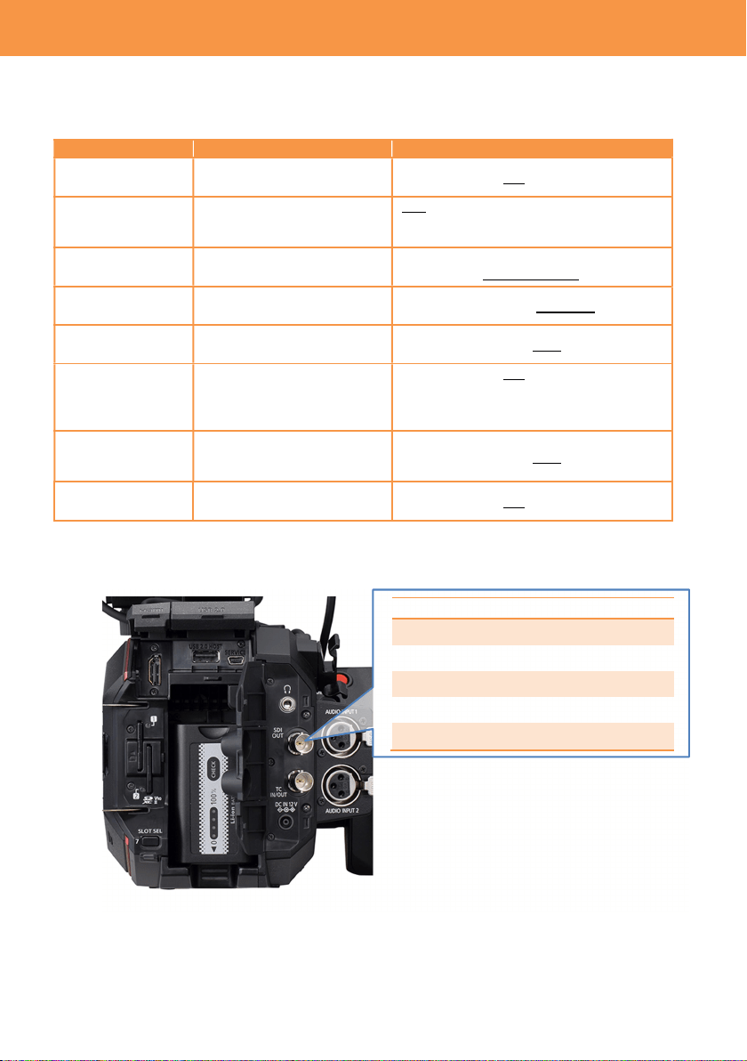
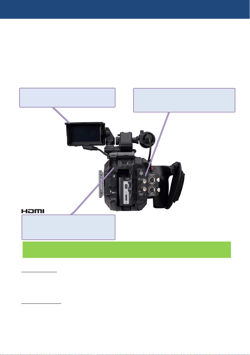
2-1. Terminals
Image resolution of HDMI and SDI OUT signals vary depend on the system settings.
See 6-3. Output signals (SDI and HDMI)(P.74-76)
REAR VIEW
2. Preparation before filming
SERVICE terminal
(for maintenance)
HDMI2.0 OUT
(Support up to
4K60p 4:2:2 10-bit)
TC IN/OUT
PHONES OUT
(3.5mm stereo)
6G SDI OUT
(Support up to
4K30p 4:2:2 10-bit)
DC12V IN
USB2.0 HOST (for Wi-Fi
adaptor connection)
11
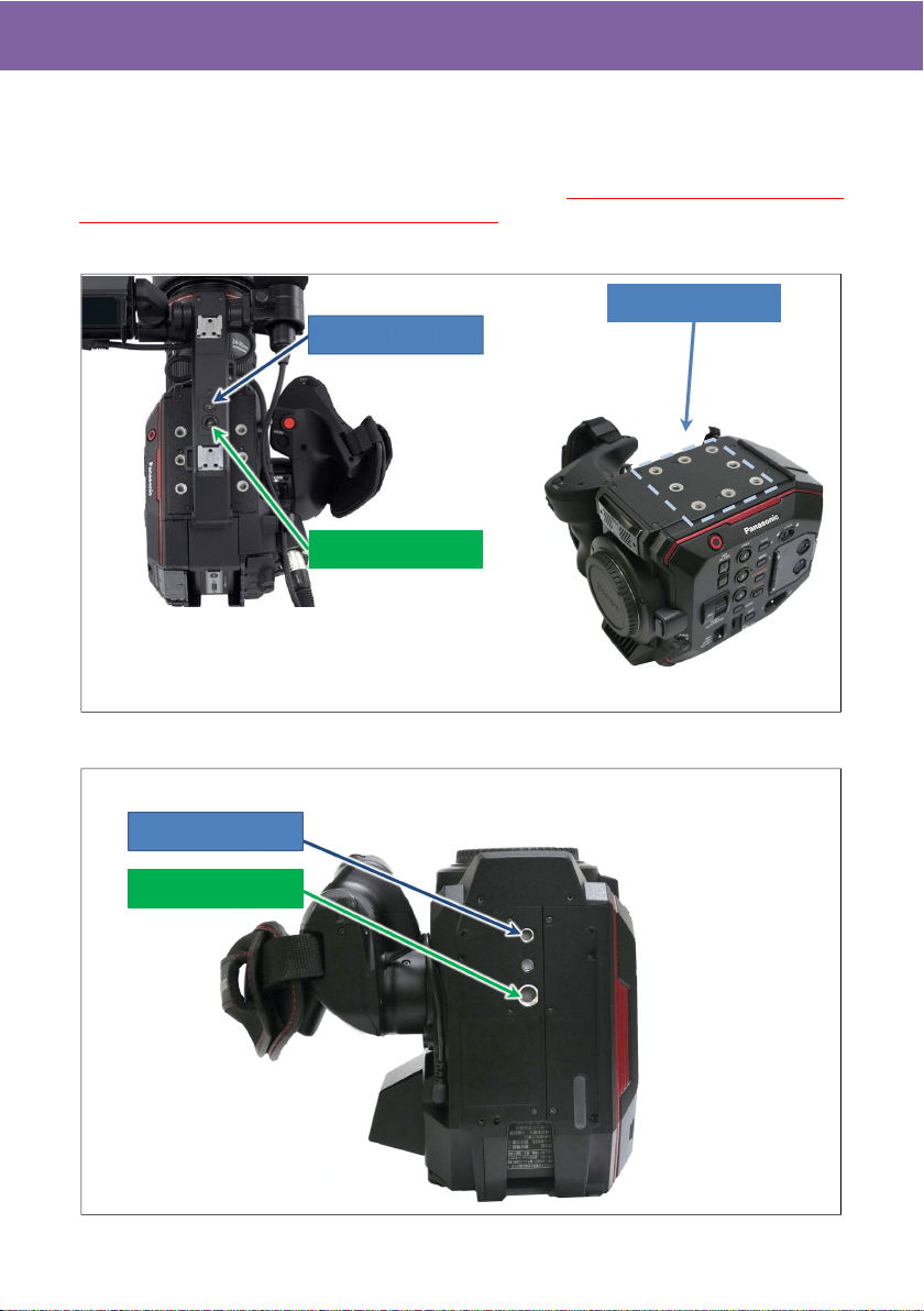
2-2. Accessory and tripod mounting holes
The AU-EVA1 has multiple standard screw holes for accessories, industrial standard
1/4-20UNC size and cinema/broadcast equipment standard 3/8-16UNC. Two holes are
prepared on the carrying handle and eight holes on the top. Use screws shorter than 5.5mm in
length, otherwise damage may occur to internal parts.
TOP VIEW
BOTTOM VIEW
2. Preparation before filming
Size 1/4-20UNC
Size 3/8-16UNC
Size 1/4-20UNC x8
Size 1/4-20UNC
Size 3/8-16UNC
Without a carrying handle
With a carrying handle
12
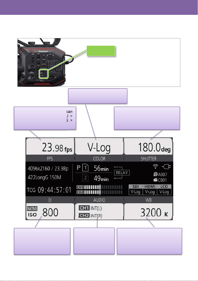
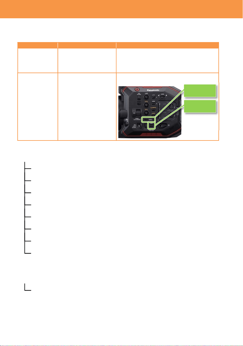
2-3. HOME screen
Centralized control screen can be recalled by pressing the HOME button. Various functions can be
rapidly accessed from this screen.
2. Preparation before filming
HOME button
Frame rate, rates to be listed can
be added/removed at MENU >
CAMERA SETTINGS > FPS >
ADD/DELETE (max.128)
COLOR (Gamma & Gamut)
See P.13 for details.
Shutter angle/speed, display mode
(deg./sec.) can be switched at
MENU > CAMERA SETTINGS >
SHUTTER > MODE
EI (Exposure Index), display
mode (ISO/dB) can be
switched at MENU > EI >
MODE
Audio settings,
See P.14 for details.
White balance preset, Values
registered in advance can be
recalled. Add/remove its value at
MENU > CAMERA SETTINGS >
WB > ADD/DELETE (max.12)
13
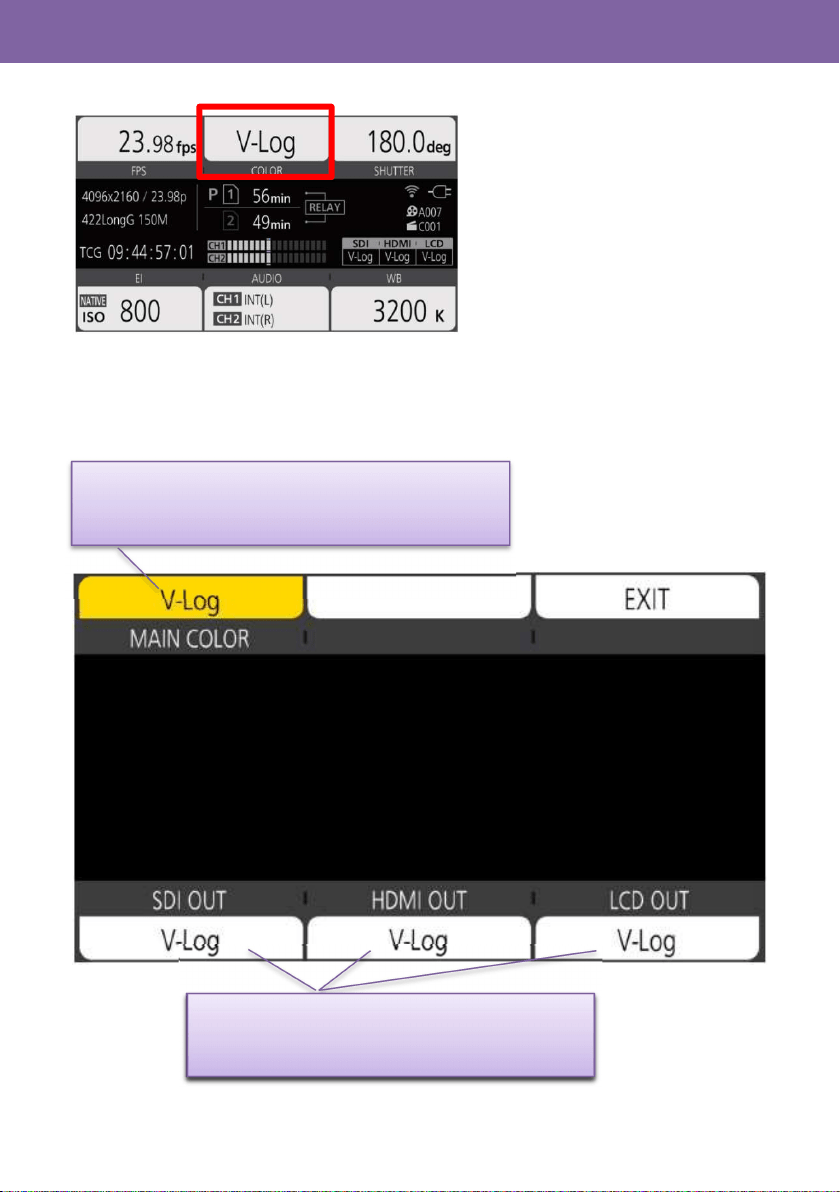
2-3-1. COLOR settings
On the AU-EVA1, settings of Gamma & Gamut is called “COLOR”. Image COLOR to be recorded
can be set in the MAIN COLOR screen. COLOR settings for SDI, HDMI, and LCD output can
individually be set.
Selectable from V-Log, SCENE1, SCENE2, SCENE3,
SCENE4, SCENE5. For more details about SCENE
settings, see 6-2. Scene file preset (P.73).
MAIN COLOR が「V-Log」の時、V-Log または V-709 を
選択可能。
MAIN COLOR が「V-Log」の時、V-Log または V-709 を
選択可能。
Selectable form V-Log or V-709 when MAIN COLOR
is set to V-Log.
2. Preparation before filming
14
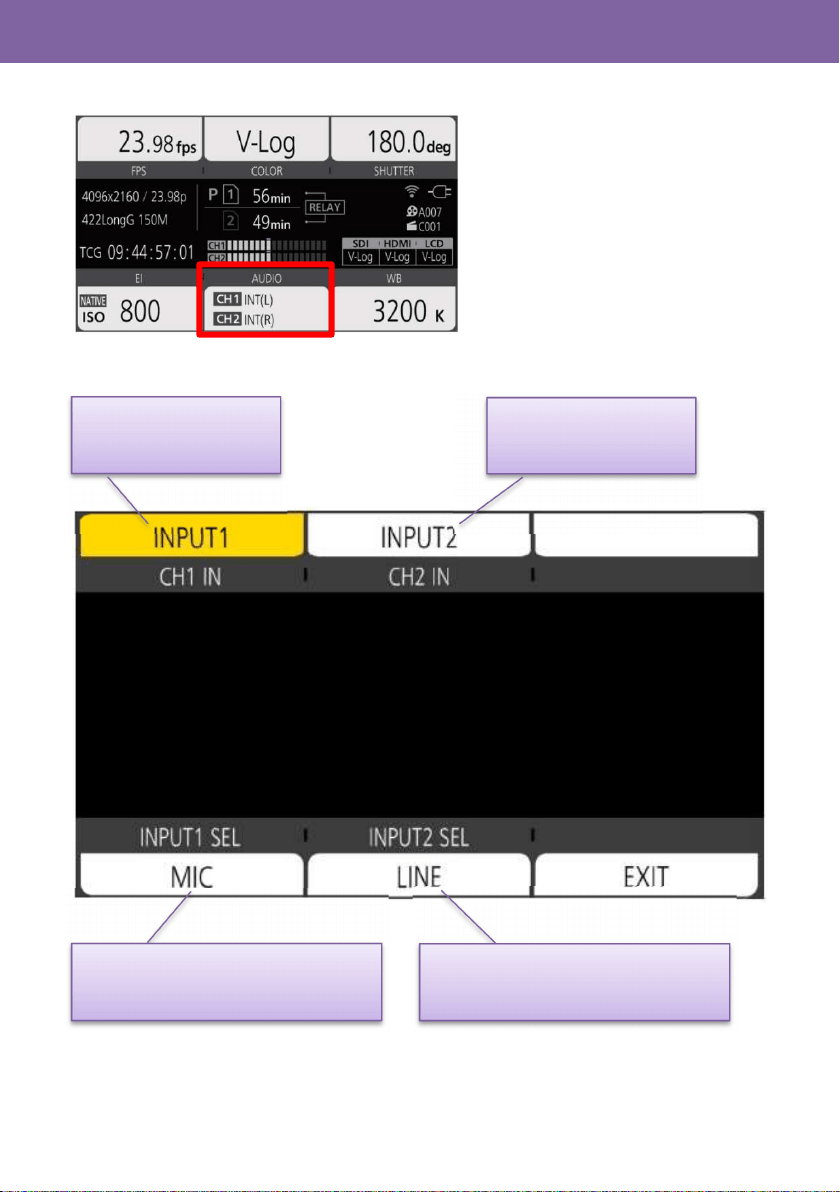
2-3-2. AUDIO setting
Assignment of audio channel sand setting of audio source.
INT(L): Built-in MIC (L)
INPUT1: AUDIO INPUT1
INT(R): Built-in MIC (R)
INPUT1: AUDIO INPUT1
INPUT2: AUDIO INPUT2
LINE: AUDIO equipment is connected
MIC: MICROPHONE is connected
2. Preparation before filming
LINE: AUDIO equipment is connected
MIC: MICROPHONE is connected
15
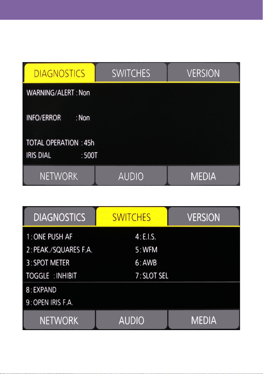
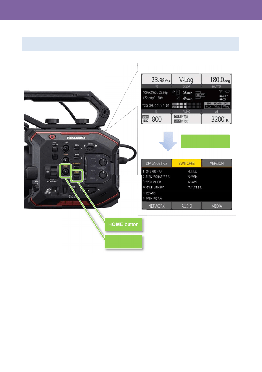
2-3-3. INFO screen
This screen can be displayed by pressing INFO button in HOME screen mode.
DIAGNOSTIC: See 6-4. Error and warning system (P.77) for details of error and warning
messages.
SWITCHES: Displays functions assigned to USER buttons at a glance.
2. Preparation before filming
16
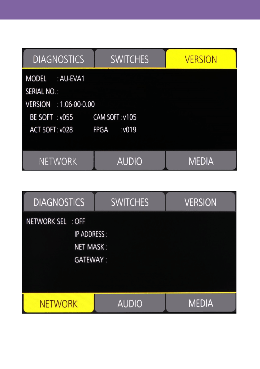
2-3-3. INFO screen (continued)
VERSION: Displays firmware version of the unit.
NETWORK: Displays network related settings.
2. Preparation before filming
17
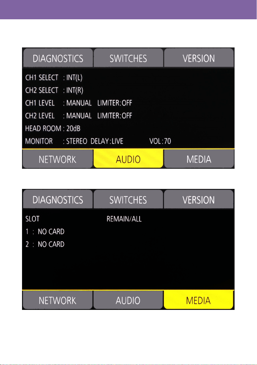
2-3-3. INFO screen (continued)
AUDIO: Displays audio related settings.
MEDIA: Displays memory card status.
2. Preparation before filming
18
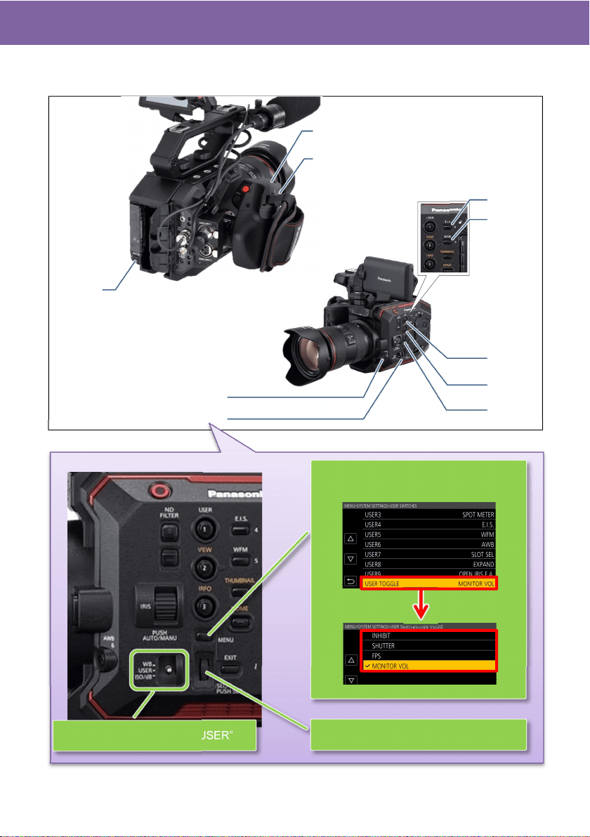
2-4. User assignable buttons
Features can quickly be recalled from 9 user assignable buttons and a dial.
1. Choose one of the features (shutter,
frame rate, audio monitor volume)
USER 1
USER 2
USER 3
USER 4
USER 5
(EIS)
(AWB)
(WFM
)
USER 7
(SLOT SEL
)
USER 8
(EXPAND
)
USER 9
USER 6
2. Preparation before filming
USER TOGGLE
2. Set the toggle SW to “USER”
3. Operate assigned feature directly
(ONE PUSH AF)
(PEAK/SQUARES FA)
(SPOT METER)
(OPEN IRIS FA)
19
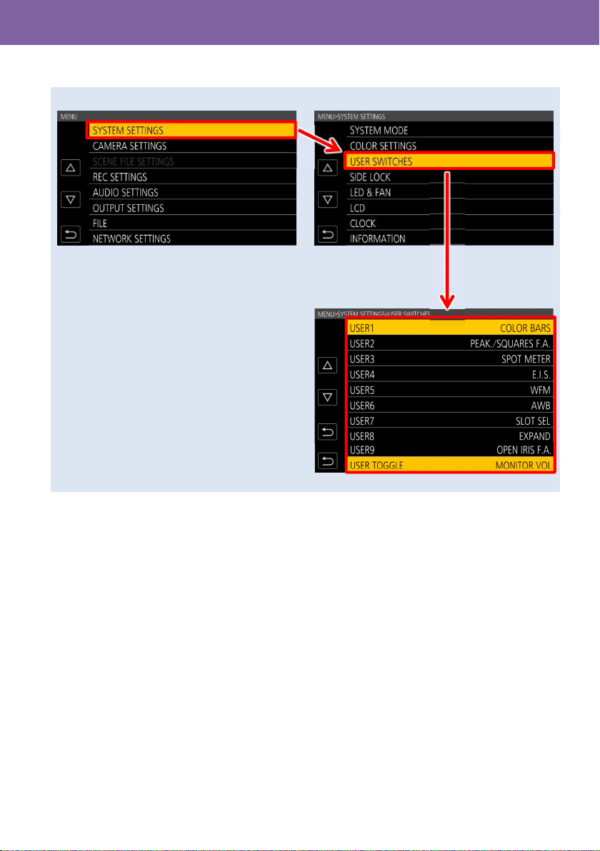
2-4-1. Assigning features
MENU > SYSTEM SETTINGS > USER SWITCHES > Assign any function to any button.
* See P.20 for assignable functions including their details.
2. Preparation before filming
20
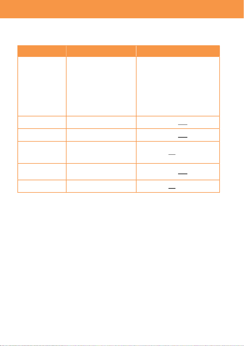
2-4-2. Assignable functions
( ) : Feature that turns OFF when switch off the unit once.
Menu item Description
INHIBIT The USER button is disabled (nothing is assigned).
AWB Perform the auto white balance adjustment.
ONE PUSH AF
Focus mode becomes AUTO while keep pressing the USER button. This
function works with lenses equipped with AF function.
ONE PUSH A.IRIS Iris mode becomes AUTO while keep pressing the USER button.
( ) ATW LOCK Maintain and lock the last white balance achieved by ATW mode.
E.I.S. Turn ON/OFF the electric image stabilizer.
( ) D.ZOOM Use 1.4x digital zoom (electric image magnification) feature.
IR SHOOTING Turn ON/OFF the Infrared shooting feature.
REC SW Perform record start/stop.
PRE REC
Turn ON/OFF the pre-record mode. This mode allows the camera to start
recording video and audio approx. 10 seconds (when MAIN PIXEL
setting is set to 1280x720, 1920x1080, or 2048x1080), approx. 5 seconds
for the others.
REC CHECK Plays last 2 seconds of the latest recorded clip on the SD memory card.
DEL LAST CLIP Delete the last clip from the SD memory card.
SLOT SEL Switch SD memory card slots for recording/playing back.
( ) EXPAND Turn ON/OFF image magnification focus assist function.
OPEN IRIS FA
Turn ON/OFF a focus assist function that makes focusing easier by
opening aperture (i.e. by making depth of field shallower).
( )PEAK/SQUARES
FA
Turn ON/OFF peaking and square focus assist function.
Focus mode (peaking or square) can be set: MENU > OUTPUT
SETTINGS > LCD FOCUS ASSIST > PEAK/SQUARES MODE
( ) WFM
Display the waveform or vector scope on the LCD monitor. Display type
can be set in MENU > OUTPUT SETTINGS > LCD EI ASSIST > WFM
MODE
( ) SPOT METER
Turn ON/OFF the spot meter function. It is available when following menu
setting is set to “SPOT METER”.
MENU > OUTPUT SETTINGS > SDI/HDMI INDICATOR or LCD
INDICATOR
ZEBRA Turn ON/OFF the ZEBRA indicator.
LEVEL GAUGE
Display a level gauge on the LCD monitor for the horizontal and vertical
axis. Indications can be indicated up to approx.30 degrees in the
horizontal directions and, and up to approx. 30 degrees in the vertical.
LEVEL GAUGE SET
Set the current horizontal and vertical position as the reference point for
the level gauge.
SDI COLOR Switch image color (SDI OUT).
HDMI COLOR Switch image color (HDMI OUT)
LCD COLOR Switch image color (LCD OUT)
( ) LCD CLEAN
VIEW
Show/hide characters on/from the LCD OUT image.
LCD MARKER Show/hide a marker on/from the LCD OUT image.
( ) COLOR BARS Turn ON/OFF the color bars display.
( ) POWER LCD Boost up brightness of LCD panel for outdoor use.
2. Preparation before filming
21
2-4-3. Checking functions assigned to USER buttons
Press “HOME” button > “INFO” button > tap “SWITCHES”
割り付けた機能一覧(SWITCHES 画面)
HOME screen
HOME button
INFO button
Press “INFO” button
2. Preparation before filming

22
3. MENU settings
23
3-1. MENU items over view
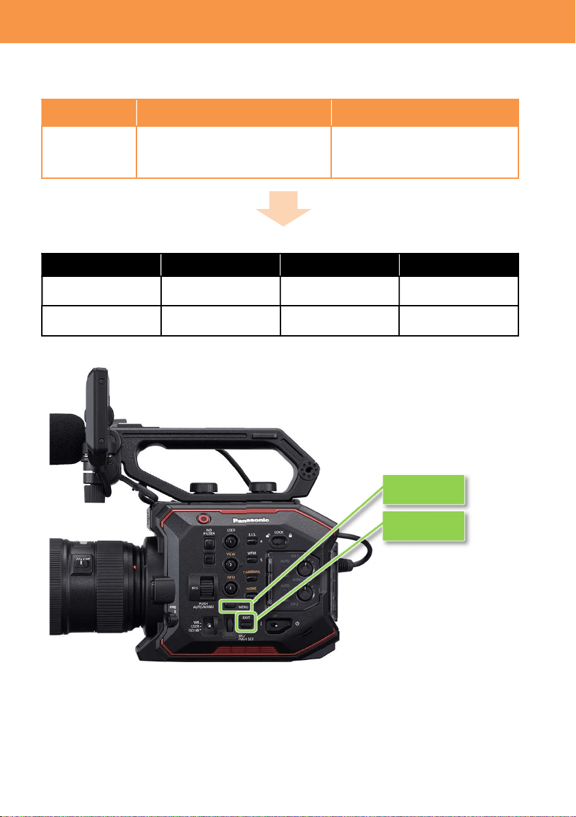
The AU-EVA1 has two levels of menu layers.
MENU Purpose How to open
MENU Most of basic and
advanced settings can be
set in this layer.
Press “MENU” button or keep pressing LCD
touch screen for 1 second while VIEW screen
is displayed.
OPTION MENU
Some initial settings. Press “MENU” button while keep pressing
“EXIT” button.
MENU (Press “MENU” button)
SYSTEM SETTINGS (Fundamental settings such as CODEC etc.) [P.24]
CAMERA SETTINGS (Sensitivity, shutter etc.) [P.28]
SCENE FILE SETTINGS (Image related settings) [P.32]
REC SETTINGS (Recording related such as Pre-REC, TC set) [P.38]
AUDIO SETTINGS (Input gain and other audio related settings) [P.40]
OUTPUT SETTINGS (HDMI, SDI, LCD output related settings) [P.42]
FILE (Loading/saving scene files, setting files) [P.50]
NETWORK SETTINGS (Wi-Fi related settings) [P.51]
OPTION MENU (Press “EXIT” + “MENU” button)
AREA SETTINGS (Region related settings) [P.53]
(NOT available for some models.)
3. MENU settings
MENU button
EXIT button
24
3-1-1. SYSTEM MODE
Menu item Description Value (factory default setting underlined)
FREQUENCY Set the system frequency 23.98p, 24.00p, 25.00p, 29.97p, 50.00p,
59.94p, 50.00i, 59.94i
SENSOR
MODE
Set the sensor drive mode
See 4-1. Understanding
Variable Frame Rate
(VFR) recording (P.55) for
the details.
S35 5.7K,
S35 MIX2.8K,
4/3 CROP&MIX 2.2K
MAIN PIXEL Set resolution for main
recorder.
4096x2160, 3840x2160, 2048x1080,
1920x1080, 1280x720
MAIN CODEC Set the main record codec
MOV
420LongGOP150M, 420LongGOP100M,
420LongGOP50M, 422LongGOP150M,
422LongGOP100M, 422LongGOP50M
AVCHD
AVCHD PS, AVCHD PH, AVCHD HA, AVCHD
PM
3-1-2. COLOR SETTINGS
Menu item Description Value (factory default setting underlined)
MAIN Set the COLOR to be
recorded as the system
color.
V-Log,
SCENE1, SCENE2, SCENE3, SCENE4,
SCENE5
SDI OUT Set the COLOR of image
to be output from SDI OUT.
When
MAIN
item is set to
“
V
-
Log
”
V-Log, V-709
When MAIN item is set to ”SCENE *”
The SCENE* is applied.
HDMI OUT Set the COLOR of image
to be output from HDMI
OUT.
When
MAIN
item is set to
“V
-
Log”
V-Log, V-709
When MAIN item is set to ”SCENE *”
The SCENE* is applied.
LCD OUT Set the COLOR of image
to be output from LCD
OUT.
When
MAIN
item is set to
“V
-
Log”
V-Log, V-709
When MAIN item is set to ”SCENE *”
The SCENE* is applied.
About V-Log and V-709
V-Log
V-Log is an image capture log curve that achieves wider latitude (+14 stops)
and fine scene gradations.
V-709
V-709 is a gamma curve, whose characteristic allows direct pre-viewing of
camera images on a TV monitor.
3. MENU settings (SYSTEM SETTINGS)
25
3-1-3. USER SWITCHES
Menu item
Description
Value (factory default setting underlined)
USER 1 ONE PUSH AF
Features can be assigned to 9 user buttons
and a dial.
See 2-4. User assignable buttons (P.18) for
the details.
USER 2 PEAK/SQUARES F.A.
USER 3 SPOT METER
USER 4 E.I.S.
USER 5 WFM
USER 6 AWB
USER 7 SLOT SEL
USER 8 EXPAND
USER 9 OPEN IRIS F.A.
USER TOGGLE MONITOR VOL
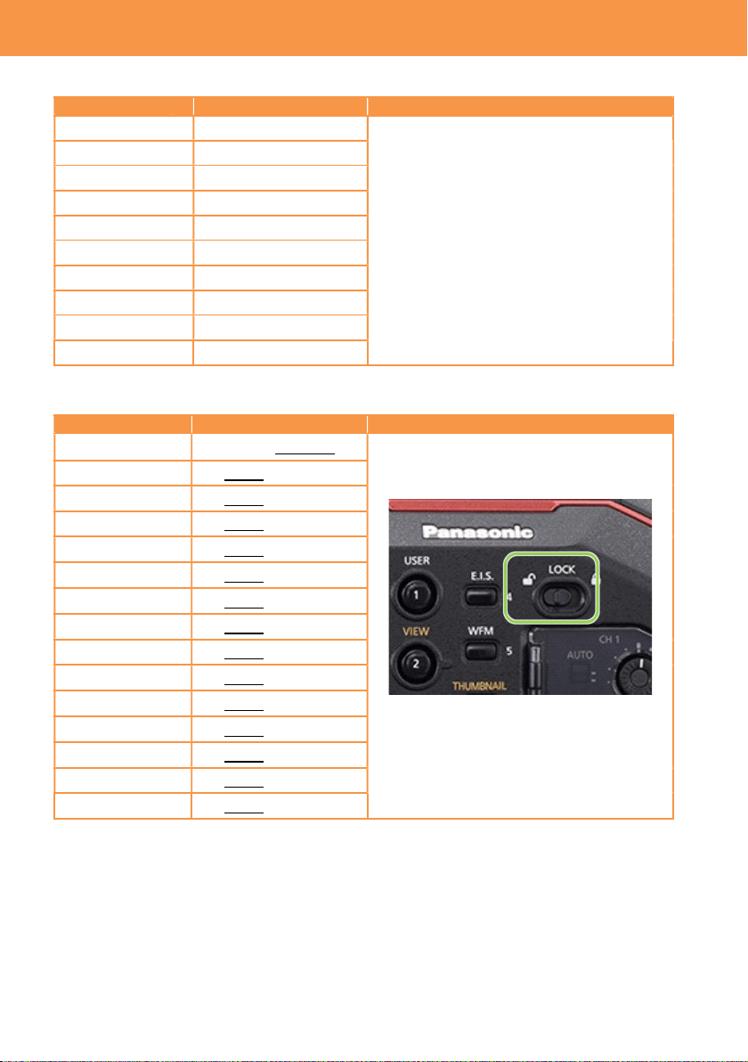
3-1-4. SIDE LOCK
Menu item Description Value (factory default setting underlined)
REC LOCK , UNLOCK
The AU-EVA1 has a key lock switch, Keys
and a Dial to be locked or not can be
selected.
LOCK switch located at left side of the unit
USER 1 LOCK , UNLOCK
USER 2 LOCK , UNLOCK
USER 3 LOCK , UNLOCK
USER 4 LOCK , UNLOCK
USER 5 LOCK , UNLOCK
USER 6 LOCK , UNLOCK
USER 7 LOCK , UNLOCK
THUMBNAIL LOCK , UNLOCK
HOME LOCK , UNLOCK
ND FILTER LOCK , UNLOCK
IRIS DIAL LOCK , UNLOCK
MENU LOCK , UNLOCK
EXIT LOCK , UNLOCK
MULTI DIAL LOCK , UNLOCK
3. MENU settings (SYSTEM SETTINGS)
26
3-1-5. LED & FAN
Menu item Description
Value (factory default setting
underlined)
TALLY LED
Set the tally lamp to be used
during recording.
FRONT, REAR, BOTH, OFF
ACCESS LED
Set the access lamp to be used
when accessing memory card.
ON, OFF
POWER LED Set the power indicator to be used.
ON, OFF
FAN SPEED
Set rotation mode of the cooling
fan.
AUTO: Adjust rotation speed in
response to inside temperature of the
unit.
FULL: Rotate at a constant speed
3-1-6. LCD
Menu item Description
Value (factory default setting
underlined)
BRIGHTNESS Adjust the brightness of the LCD
monitor.
-15 -- 0 -- 15
COLOR LEVEL
Adjust the saturation level of the
LCD monitor.
-15 -- 0 -- 15
CONTRAST Adjust the contrast level of the
LCD monitor.
-30 -- 0 -- 30
BACK LIGHT Adjust brightness of the backlight
of the LCD monitor.
-1 , 0 , 1
3-1-7. CLOCK
Menu item Description
Value (factory default setting
underlined)
CLOCK
SETTING
Set the built-in calendar. ---
TIME ZONE
Set time difference to the calendar
information.
-12:00 -- +13:00
DATE FORMAT
Set date format. Y-M-D , M-D-Y , D-M-Y
3-1-8. INFORMATION
Menu item Description
Value (factory default setting
underlined)
VERSION
MODEL Display product model number
SERIAL NO. Display serial number
VERSION Display firmware version
OPERATION
TIME
TOTAL OPERATION
Display accumulated power on time
in hours.
IRIS DIAL
Display accumulated operation (turn)
times of IRIS dial in x100 times.
SENSOR TEMP
Display ambient temperature of the
image sensor in C degree.
Example 000037 = 37°C
USB SERVICE
MODE
For service purpose ---
UPDATE
For firmware update operation ---
3. MENU settings (SYSTEM SETTINGS)

27
3-1-9. LANGUAGE
Menu item Description Value (factory default setting underlined)
LANGUAGE Set the menu language ---
* This menu item will not be displayed for some models and when the AREA SETTING item in
the OPTION MENU is set to “AREA1”.
3-1-10. INITIALIZE
Menu item Description Value (factory default setting underlined)
LOAD
FACTORY DATA
Restore the product to
factory settings.
YES , NO
3. MENU settings (SYSTEM SETTINGS)
28
3-1-11. FPS
Menu item Description Value (factory default setting underlined)
VFR SW Turn ON/OFF variable
frame rate mode.
ON , OFF
VALUE Set frame rate. The maximum number of frame rate (FPS) can
vary depends on setting “SYSTEM SETTING >
SENSOR MODE”.
SENSOR MODE and maximum FPS
S35 5.7K : max. 60fps
S35 MIX 2.8K : max. 120fps
4/3 CROP&MIX 2.2K : max. 240fps
See 4-1. Understanding Variable Frame Rate
(VFR) recording (P.55) for details of SENSOR
MODE settings
ADD Set frame rates to be
selected.
(maximum 150 values)
EDIT Edit information of
selectable frame rates
---
DELETE Remove FPS value from
the select list.
---
3-1-12. SHUTTER
Menu item Description Value (factory default setting underlined)
SW Turn ON/OFF the
electric shutter.
ON , OFF
MODE Switch display unit of the
shutter.
Sec (speed) , deg (open angle)
deg
VALUE deg
Recall open angle of
shutter on a preset table.
HALF SHUTTER, 11.5d, 22.5d, 45.0d, 90.0d,
120.0d, 144.0d, 172.8d, 180.0d, 270.0d, 357.0d
ADD deg Add an open angle to the
preset table. (max.12)
---
EDIT deg Edit the shutter preset
table.
---
DELETE
deg
Delete an open angle
from the preset table.
---
sec
VALUE sec
Recall a speed on a
preset table.
HALF SHUTTER, 1/60.0, 1/100.0, 1/120.0,
1/250, 1/500, 1/1000, 1/2000
ADD sec Add a speed to the
preset table. (max.12)
---
EDIT sec Edit the shutter preset
table.
---
DELETE
sec
Delete a speed from the
preset table.
---
3. MENU settings (CAMERA SETTINGS)

29
3-1-13. EI
Menu item Description Value (factory default setting underlined)
MODE Set unit of Exposure Index
(EI)
ISO , dB
ISO SELECT Set the EI control mode
when ISO is selected in the
MODE item.
NATIVE ONLY, 800BASE, 2500BASE
NATIVE ISO Select the value of ISO value
when NATIVE ONLY is
selected.
When GAMMA SELECT is set to “VIDEO”
400 ISO, 1250 ISO
When other value is chosen for GAMMA
SELECT
800 ISO, 2500 ISO
800BASE ISO
Select the value of ISO value
when 800 BASE is selected.
When GAMMA SELECT is set to “VIDEO”
200, 250, 320, 400, 500, 640, 800, 1000ISO
When other value is chosen for GAMMA
SELECT
200, 250, 320, 400, 500, 640, 800, 1000, 1250,
1600, 2000 ISO
2500BASE
ISO
Select the value of ISO value
when 2500 BASE is
selected.
When GAMMA SELECT is set to “VIDEO”
640, 800, 1000, 1250, 1600, 2000, 2500, 3200,
4000, 5000, 6400, 8000, 10000, 12800, 16000,
20000, 25600ISO
When other value is chosen for GAMMA
SELECT
1000, 1250, 1600, 2000, 2500, 3200, 4000,
5000, 6400, 8000, 10000, 12800, 16000,
20000, 25600ISO
GAIN MODE Set the EI control mode
when dB is selected in the
MODE item.
NORMAL, HIGH
GAIN
SELECT
GAIN MODE = NORMAL
When GAMMA SELECT is set to “VIDEO”
-6dB, -4dB, -2dB, 0dB, 2dB, 4dB, 6dB, 8dB
When other value is chosen for GAMMA
SELECT
-12dB, -10dB, -8dB, -6dB, -4dB, -2dB, 0dB,
2dB, 4dB, 6dB, 8dB
GAIN MODE = HIGH
When GAMMA SELECT is set to “VIDEO”
-6dB, -4dB, -2dB, 0dB, 2dB, 4dB, 6dB, 8dB,
10dB, 12dB, 14dB, 16dB, 18dB, 20dB, 22dB,
24dB, 26dB
When other value is chosen for GAMMA
SELECT
-8dB, -6dB, -4dB, -2dB, 0dB, 2dB, 4dB, 6dB,
8dB, 10dB, 12dB, 14dB, 16dB, 18dB, 20dB
3. MENU settings (CAMERA SETTINGS)
30
3-1-14. WHITE
Menu item
Description Value (factory default setting underlined)
AWB Perform Auto white balance
adjustment
Available when VALUE item is set to “AWB
MEMORY” only.
VALUE Recall auto white balance
value on a preset table.
ATW, AWB MEMORY, 3200K+0.0GMg,
4300K+0.0GMg, 5600K+0.0GMg,
6300K+0.0GMg
ADD Add an AWB value to the
preset table. (max.12)
---
EDIT Edit the preset table.
---
DELETE Delete a value from the
preset table.
---
3-1-15. NR
Menu item
Description Value (factory default setting underlined)
ISO800 Set amount of reduction in
800 BASE ISO mode.
2 , 1 , OFF
ISO2500 Set amount of reduction in
2500 BASE ISO mode.
2 , 1 , OFF
3-1-16. LENS SETTING
Menu item
Description Value (factory default setting underlined)
A.IRIS
LEVEL
EFFECT
Set the target brightness
level in auto iris mode. 0 -- 50 -- 100
A.IRIS
WINDOW
Set the auto iris detection
window.
NORMAL1: Window is set to center
NORMAL2: Window is set to bottom side
CENTER: Window is set to center (spot)
A.IRIS
PEAK/AVE
Set a ratio of auto iris control
(peak or average)
0 -- 30 -- 100
Auto iris response becomes sensitive when
increase the value.
GRIP IRIS Set control direction for the
dial on the hand-grip part.
RIGHT OPEN:
Iris opens when turn the dial outward.
LEFT OPEN:
Iris opens when turn the dial inward.
AF OFFSET
Adjust offset of focus
position.
Near -20 -- 0 -- 20 Far
3-1-17. IR SHOOTING
Menu item
Description Value (factory default setting underlined)
IR
SHOOTING
Turn ON/OFF infrared
shooting mode.
ON, OFF
3. MENU settings (CAMERA SETTINGS)

31
3-1-18. E.I.S.
Menu item
Description Value (factory default setting underlined)
SW Turn ON/OFF electric image
stabilizer.
ON, OFF
ZOOM
POSITION
DATA
Set focal length of the lens for
precise electric image stabilizing
operation.
AUTO, MANUAL
For AUTO adjustment, EF lenses that
support providing focal length information is
required.
ZOOM
POSITION
VALUE
Set focal length of the lens
currently mounted.
*Available when ZOOM
POSITION DATA item is set to
“MANUAL”.
8 – 200
3-1-19. AUTO BLACK BALANCE
Menu item
Description Value (factory default setting underlined)
ABB
Perform Auto Black Balance
adjustment.
---
3. MENU settings (CAMERA SETTINGS)

32
3-1-20. NAME EDIT
Menu item Description Value (factory default setting underlined)
NAME EDIT Edit scene file name Max. eight characters
3-1-21. SCENE DATA
Menu item Description Value (factory default setting underlined)
LOAD Load custom scene files from
the built-in memory.
YES, NO
SAVE Save custom scene files to the
built-in memory.
YES, NO
INITIALIZE Restore scene files to the
factory settings.
YES, NO
3-1-22. BLACK
Menu item Description Value (factory default setting underlined)
M.PED
Set the master pedestal level
(reference of black).
-100 -- 0 -- 100
R PED
Set the pedestal level for Red
channel.
-100 -- 0 -- 100
G PED
Set the pedestal level for
Green channel.
-100 -- 0 -- 100
B PED
Set the pedestal level for Blue
channel.
-100 -- 0 -- 100
PEDESTAL
OFFSET
Select behavior of pedestal
level after ABB performed.
ON: Add pedestal offset of R PED, G
PED, and B PED after ABB is performed.
OFF: Clear all values of R PED, G PED,
and B PED after ABB is performed.
3. MENU settings (SCENE FILE SETTINGS)
33
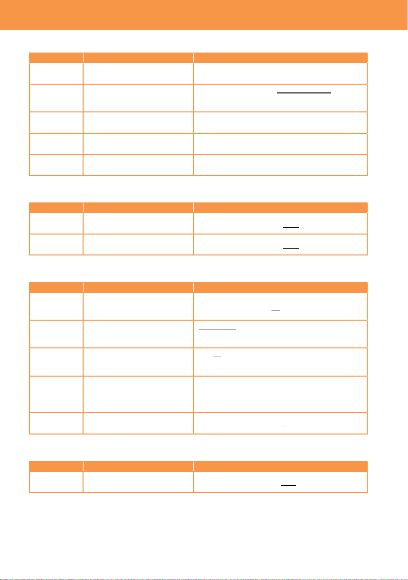
3-1-23. GAMMA
Menu item Description Value (factory default setting underlined)
GAMMA
SELECT
Set gamma mode V-255570L1, V-504580L1, VIDEO, HLG
3. MENU settings (SCENE FILE SETTINGS)
V-Log
V-255570L1
V-504580L1
Output (%)
Output (%)
Output (%)
(%)
VIDEO
Input (dynamic range, %)
HLG
V-255570L1: Attaching importance to contrast
The curve has 14 stop of latitude. The V-255570 means that start curve angle up to 10%
is approx. 2.5x, gamma value 0.55 up to 70%. Recommended face tone level range 40 to 50%.
V-504580L1: Attaching importance to softer image
The curve has 14 stop of latitude. The V-504580 means that start curve angle up to 10%
is approx. 5.0x, gamma value 0.45 up to 80%. Recommended face tone level range 40 to 60%.
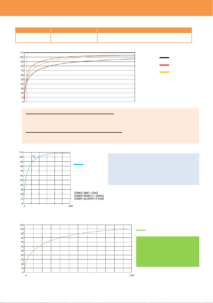
HLG
The hybrid log gamma curve,
which has much wider 1200%
of dynamic range. The BT.2020
equivalent color space is
applied.
VIDEO: Broadcast look
It is designed to express conventional video
camera’s characteristic with 600% of dynamic
range.
Input (dynamic range, %)
6 Input (stop) 0
34
GAMMA (continued)
Menu item Description Value (factory default setting underlined)
MASTER GAMMA
Set master gamma curve
in units of 0.01.
0.30 -- 0.75
BLACK GAMMA Set depression and
expansion of gamma
curve for dark areas.
(Depressing) -8 -- OFF -- +8 (Expanding)
B.GAMMA
RANGE
Set the maximum level of
compression/expansion.
1 : Approx. 20%
2 : Approx. 30%
3 : Approx. 40%
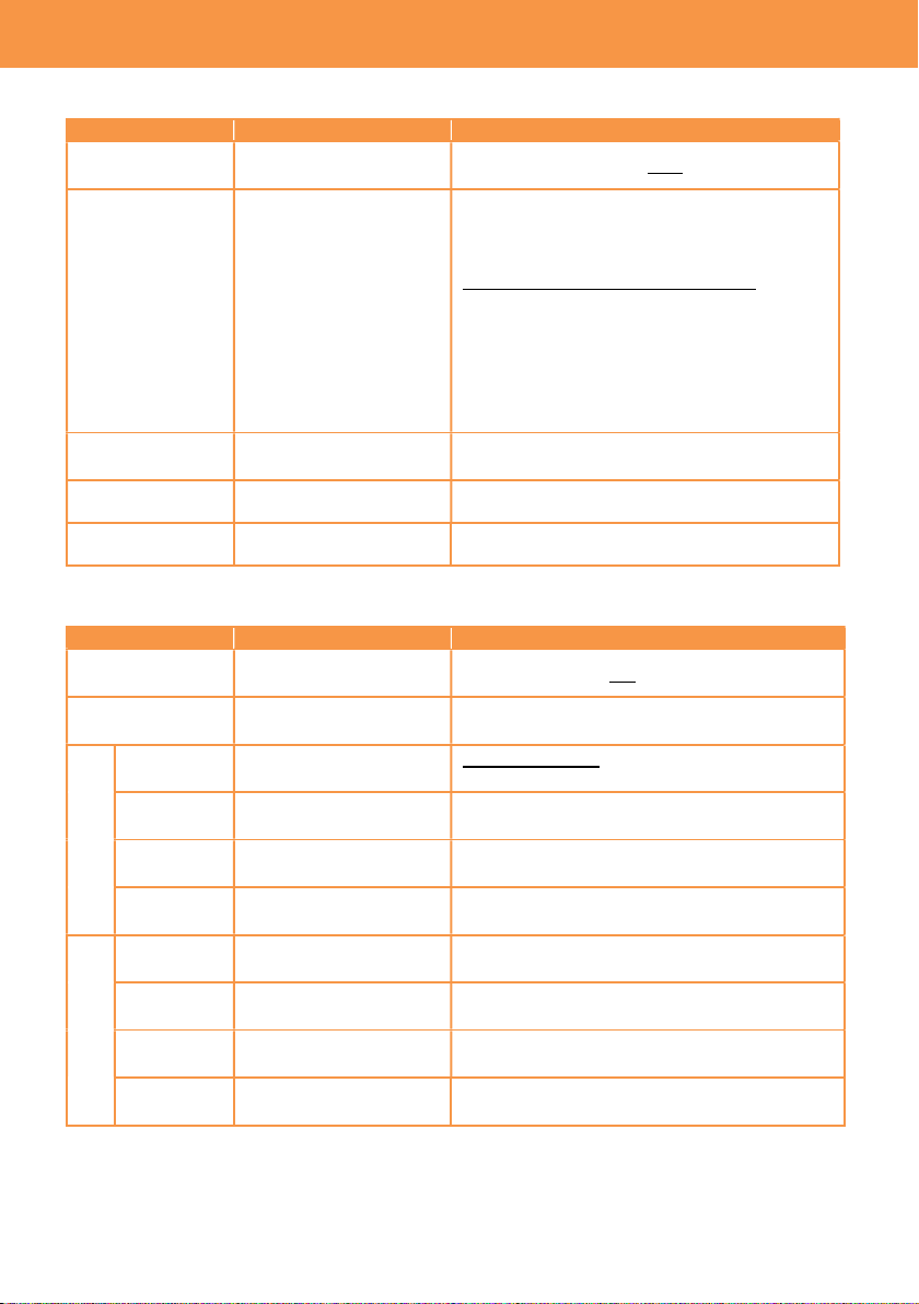
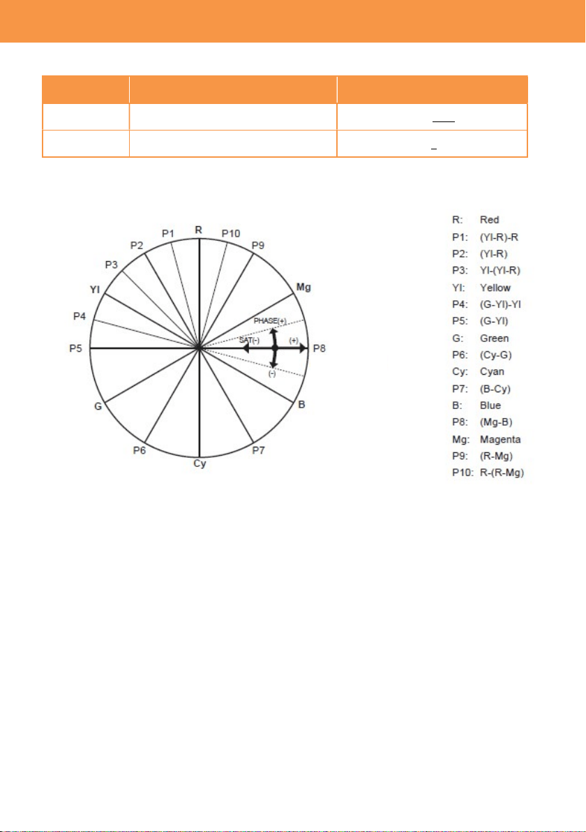
3-1-24. KNEE
Menu item Description Value (factory default setting underlined)
KNEE SW Turn ON/OFF the KNEE. ON, OFF
KNEE MODE Set the KNEE mode. D RANGE, PRESS
KNEE POINT
Set the KNEE point in
units of 1%.
55% -- 85% -- 100%
KNEE SLOPE Set the KNEE slope. 0 – 100
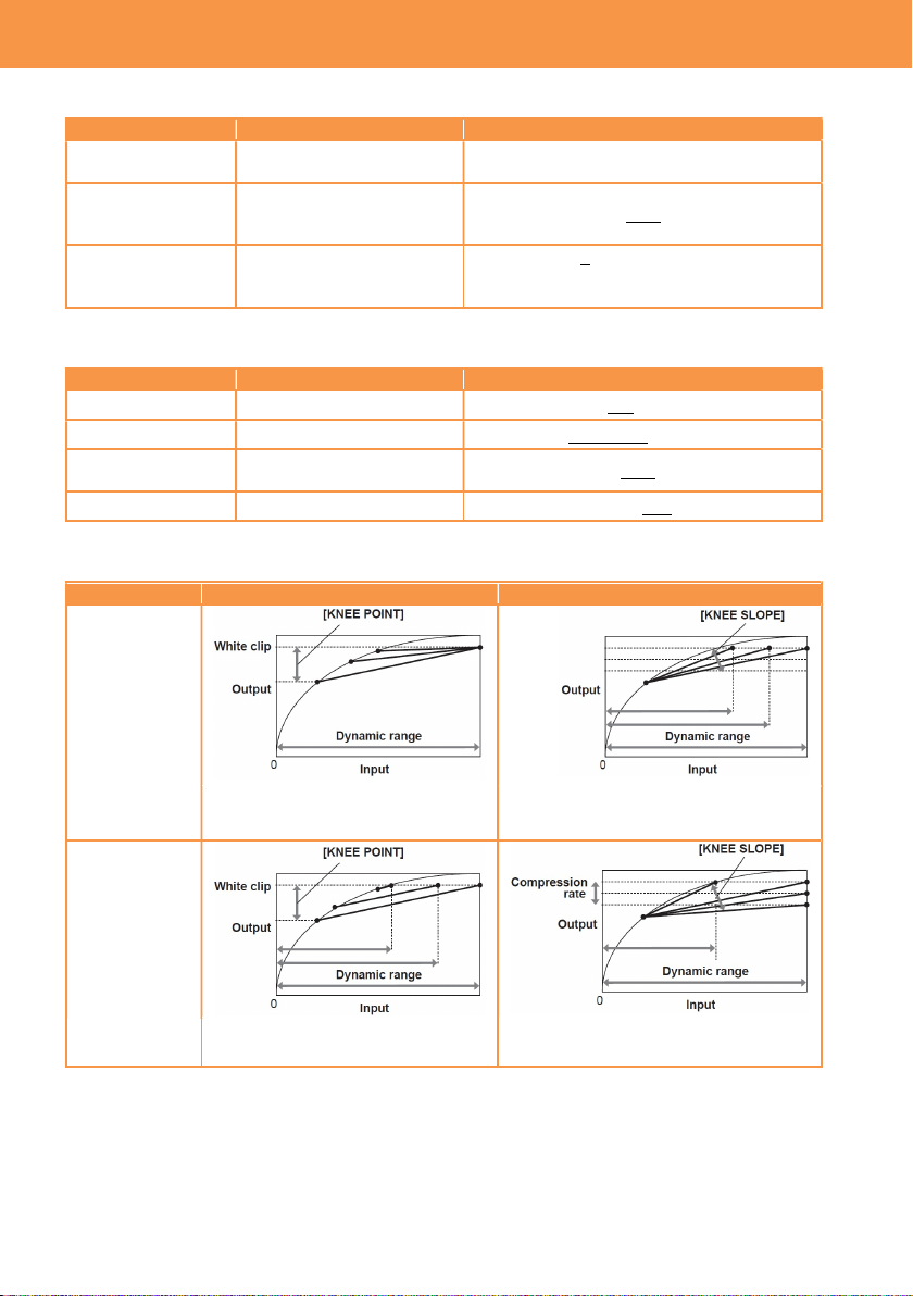
KNEE Effect
KNEE MODE
KNEE POINT
KNEE SLOPE
D RANGE
Does not affect dynamic range
Dynamic range varies with KNEE
SLOPE control
PRESS
Dynamic range varies with KNEE
POINT control
Dynamic range and signal
compression level vary
3. MENU settings (SCENE FILE SETTINGS)
35
3-1-25. HLG KNEE
Menu item Description Value (factory default setting underlined)
KNEE SW
Turn ON/OFF the Knee in HLG
gamma mode.
ON, OFF
KNEE POINT
Set the Knee point in HLG
gamma mode in the units of 1%.
55% -- 109%
KNEE SLOPE
Set the Knee slope in HLG
gamma mode.
0 -- 10 -- 100
3-1-26. WHITE CLIP
Menu item Description Value (factory default setting underlined)
SW Turn ON/OFF the white clip. ON, OFF
LEVEL Set white clip level. 90% -- 109%
3-1-27. DETAIL
Menu item Description Value (factory default setting underlined)
SW Turn ON/OFF the contour
correction.
ON, OFF
CORING Adjust threshold level of image
contour correction.
0 -- 60
MASTER
LEVEL
Adjust the contour correction
level for entire image.
-31 -- 0 -- 31
FREQUENCY
Set thickness of image contour
correction level.
1 , 2 , 3
3-1-28. SKIN DETAIL
Menu item Description Value (factory default setting underlined)
SKIN DTL1
Select the skin color table of the
object to apply the skin tone
table to.
ON , OFF
SKIN DTL2
ON , OFF
SKIN DTL3
ON , OFF
3. MENU settings (SCENE FILE SETTINGS)
36
3-1-29. CHROMA
Menu item Description Value (factory default setting underlined)
LEVEL
Set chroma level of Pb and Pr
signals.
OFF, -99% -- 0% -- 99%
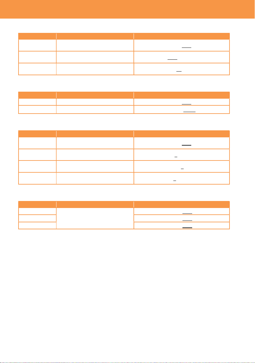
3-1-30. MATRIX
Menu item Description Value (factory default setting underlined)
SW
Turn ON/OFF the color matrix
adjustment.
ON, OFF
R-G
Adjust the linear matrix
-63 -- 0 -- 63
R-B
Adjust the linear matrix
-63 -- 0 -- 63
G-R
Adjust the linear matrix
-63 -- 0 -- 63
G-B
Adjust the linear matrix
-63 -- 0 -- 63
B-R
Adjust the linear matrix
-63 -- 0 -- 63
B-G
Adjust the linear matrix
-63 -- 0 -- 63
Effect of MATRIX adjustment
Reference axis
3. MENU settings (SCENE FILE SETTINGS)
37
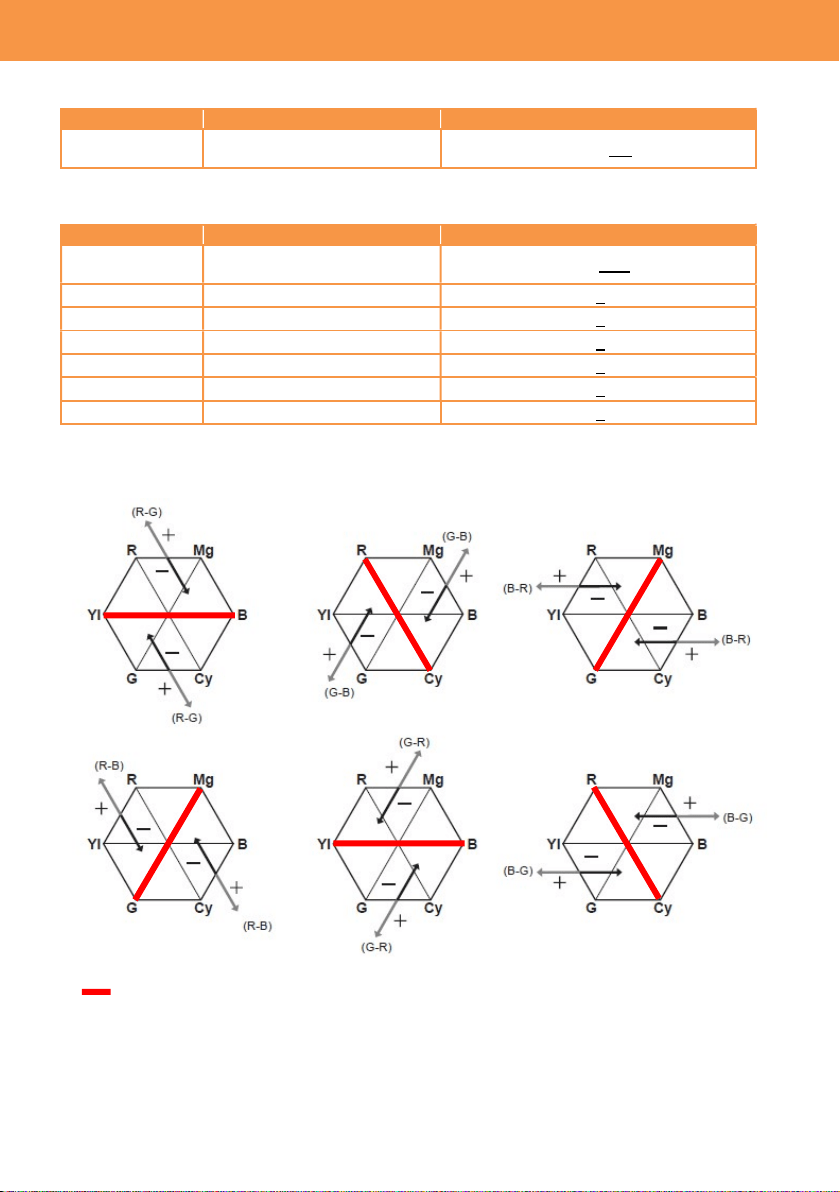
3-1-31. COLOR CORRECTION
Menu item Description Value (factory default setting
underlined)
SW Turn ON/OFF the color correction. ON, OFF
PARAM
Set saturation and phase of color on
16 color axes of a picture.
-63 -- 0 -- 63
Effect of color correction
3. MENU settings (SCENE FILE SETTINGS)
38
3-1-32. CARDS/MEDIA
Menu item Description Value (factory default setting underlined)
FORMAT
MEDIA
Perform SD card format. SLOT1 , SLOT2
3-1-33. CLIP NAME
Menu item Description Value (factory default setting underlined)
CAM INDEX Set the camera ID code, to be
recorded as the initial letter of
the clip name in MOV format.
A -- Z
NEXT REEL
COUNT
Set the incremental reel
number, to be recorded
(second to fourth letter of the
clip name in MOV format.
001 -- 999
* See 5-3. File name (MOV format) (P.70) for the details.
3-1-34. 2 SLOTS FUNC.
Menu item Description Value (factory default setting underlined)
2 SLOT FUNC. Set the record mode, using two
SD memory cards.
OFF, RELAY REC, SIMUL REC
3-1-35. PRE REC
Menu item Description Value (factory default setting underlined)
PRE REC Turn ON/OFF the pre-record
mode. This mode allows the
camera to capture and
record video and audio from
approx. 10 seconds before
REC is started (when MAIN
PIXEL setting is set to
1280x720, 1920x1080, or
2048x1080), or approx. 5
seconds for other modes.
ON , OFF
3-1-36. TC
Menu item Description Value (factory default setting underlined)
SET TC Set the timecode value. ---
SET UB Set the users bit information. 00 -- FF
TC/UB/Dur. Set the timecode display
mode.
TC = Timecode
UB = Users bit
Dur. = Elapsed time of recording
FREE/REC
RUN
Set the timecode count mode.
FREE RUN, REC RUN
DF/NDF
Set the timecode drop frame
mode.
DF, NDF
3. MENU settings (REC SETTINGS)

39
TC
(continued)
Menu item Description Value (factory default setting underlined)
UB MODE Set information type, to be
recorded and output from
SDI OUT.
FRAME RATE
Frame rate information
USER
Information, set on SET UB menu item
TIME
Hour, Minute, Second information
DATE
Year, Month, Day information
CLIP NAME
Clip name information
TC IN/OUT SEL Set purpose of TC IN/OUT
terminal.
TC IN: Use as TC input terminal
TC OUT: Use as TC output terminal
TC OUT REF Make value offset for the
output timecode.
RECORDING:
Output timecode without delay
SDI OUT:
Output timecode with delay so that the
value meets timing with SDI OUT image
3. MENU settings (REC SETTINGS)
40
3-1-37. AUDIO CH SETTINGS
Menu item Description
Value (factory default setting
underlined)
CH1
IN SELECT
Set audio source on the channel 1.
INT(L): Built-in microphone (L)
INPUT1: AUDIO INPUT1
CH2
IN SELECT
Set audio source on the channel 2.
INT(R): Built-in microphone(R)
INPUT1: AUDIO INPUT1
INPUT2: AUDIO INPUT2
CH1
MIC LOWCUT
Reduce the level of low frequency
sound on the audio 1.
ON, OFF
CH2
MIC LOWCUT
Reduce the level of low frequency
sound on the audio 2.
ON, OFF
CH1
LIMITER
Turn ON/OFF audio level limiter,
when input level setting on the
channel 1 is set to manual.
ON, OFF
CH2
LIMITER
Turn ON/OFF audio level limiter,
when input level setting on the
channel 2 is set to manual.
ON, OFF
HEAD ROOM Set audio reference level. 18dB, 20dB
3-1-38. AUDIO INPUT
Menu item Description
Value (factory default setting
underlined)
INPUT1
LINE/MIC SEL
Set audio level of the INPUT1.
LINE: for audio equipment
MIC: for microphone
INPUT2
LINE/MIC SEL
Set audio level of the INPUT2.
LINE: for audio equipment
MIC: for microphone
INPUT1
MIC POWER
Turn ON/OFF +48V phantom
power supply to AUDIO INPUT1.
ON, OFF
INPUT2
MIC POWER
Turn ON/OFF +48V phantom
power supply to AUDIO INPUT2.
ON, OFF
INPUT1
MIC LEVEL
Set audio level of audio input 1. -40dB, -50dB, -60dB
INPUT2
MIC LEVEL
Set audio level of audio input 2. -40dB, -50dB, -60dB
INPUT1
LINE LEVEL
Set audio level of audio input 1. 4dB, 0dB
INPUT2
LINE LEVEL
Set audio level of audio input 2. 4dB, 0dB
3. MENU settings (AUDIO SETTINGS)
41
3-1-39. AUDIO OUTPUT
Menu item Description Value (factory default setting underlined)
MONITOR OUT
Set monitor audio output
channel of phones out.
CH1, CH2, STEREO, MIX
MONITOR DELAY
Select audio output mode on
phones out. Choose “LIVE”
when delay is audible
between phones out audio
and actual sound.
LIVE, RECORDING
MONITOR VOL Set the monitor audio level. 0 -- 70 -- 100
3-1-40. REC BEEP SOUND
Menu item Description Value (factory default setting underlined)
MODE
Set if make a beep sound
when starting/stopping
recording.
OFF:
START: REC start only
STOP: REC stop only
START&STOP: Both REC start and stop
VOLUME Set the beep sound level HIGH, MED, LOW
3-1-41. ALARM
Menu item Description Value (factory default setting underlined)
BATTERY END
Set alert sound level of
battery end.
HIGH, MED, LOW, OFF
MEDIA END
Set alert sound level of short
card remain time.
HIGH, MED, LOW, OFF
3. MENU settings (AUDIO SETTINGS)
42
3-1-42. SDI OUT
Image resolution of SDI OUT signal varies depends on the combination of settings, see 6-3. Output
signals (SDI and HDMI) (P.74) for the details.
Menu item Description Value (factory default setting underlined)
OUTPUT SW Turn ON/OFF SDI signal
output.
ON, OFF
SIGNAL SEL Set output signal format on
the SDI OUT.
SDI: Vary by OUT FORMAT setting
LCD(1080p): Fix at 1920X1080p
LCD(1080i): Fix at 1920X1080i
OUT FORMAT Set SDI output format. 4096X2160p, 3840x2160p, 1920x1080p,
1920x1080i, 1920x1080PsF, 1280x720p
3G-SDI OUT Set 3G SDI output type.
LEVEL-A, LEVEL-B
SDI REC
REMOTE
Enable recording remote via
SDI terminal.
ON, OFF
INDICATOR DISP
Show indicator (information
of fps, audio level, etc. like
LCD monitor) on the SDI
OUT.
ON, OFF
*Indicator forcedly hidden while menu
screen is displayed on the LCD monitor.
MARKER DISP Show marker (center
marker, aspect marker etc.)
on the SDI OUT.
ON, OFF
MENU DISP Show menu characters on
the SDI OUT.
ON, OFF
SDI signal format and output format (resolution)
OUT FORMAT SDI FORMAT
4096x2160p 6G SDI
3840x2160p 6G SDI
1920x1080p 3G SDI
1920x1080i 1.5G SDI
1280x720p 1.5G SDI
3. MENU settings (OUTPUT SETTINGS)
43
3-1-43. HDMI OUT
Image resolution of HDMI OUT signal varies depends on the combination of settings, see 6-3.
Output signals (SDI and HDMI) (P.74) for the details.
Menu item Description Value (factory default setting
underlined)
OUT FORMAT Set output signal format on the
HDMI OUT.
4096X2160p *1
4096x2160p (420/8bit)
3840x2160p *1
3840x2160p (420/8bit)
1920x1080p
1920x1080i,
1280x720p
720x480p
720x576p
*1 4:2:2 10bit
HDMI TC OUT Add timecode information on
the HDMIOUT.
ON, OFF
HDMI REC
REMOTE
Enable recording remote via
HDMI terminal.
ON, OFF
INDICATOR DISP Show/hide indicator
(information of fps, audio level,
etc. like LCD monitor) on the
HDMI OUT.
ON, OFF
MARKER DISP Show marker (center marker,
aspect marker etc.) on the
HDMI OUT.
ON, OFF
MENU DISP Show menu characters on the
HDMI OUT.
ON, OFF
3. MENU settings (OUTPUT SETTINGS)
44
3-1-44. SDI/HDMI INDICATOR
Camera status information to be shown on the image can be set individually by SDI/HDMI OUTs.
Menu item Description
CLIP NAME Clip name
PIXEL/FREQ System resolution and frequency for the main recorder
MAIN COLOR COLOR (Gamma & Gamut) for the main recorder
REC FORMAT Record codec for the main recorder
SLOT 1/2 STATUS Status of card slots, and remaining time
2 SLOTS FUNC Current record mode of 2SLOT function (Relay or Simul)
TC Timecode, users bit, elapsed record time etc.
BATTERY REMAIN
Remaining battery
REC REMOTE Status of REC/PAUSE, for equipment connected to SDI/HDMI OUTs.
AUDIO LEVEL
METER
Audio level meter
FPS Frame rate in FPS
SHUTTER Shutter speed / open angle
EI Exposure index
WHITE Status of white balance adjustment
IRIS/ZOOM Zoom position and aperture level of the lens
ND FILTER ND filter position
E.I.S./D.ZOOM Status of Electric Image Stabilizer (EIS) and digital zoom
WLAN Connection status of Wi-Fi
IR SHOOTING Status of Infrared record mode
SPOT METER
Measurement result of the spot meter in STOP / %
*The unit “STOP” can be selected in V-Log mode (MENU > LCD EI
ASSIST > SPOT EMTER UNIT item).
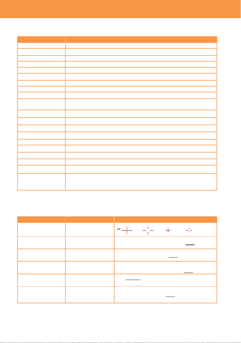
3-1-45. SDI/HDMI MARKER
Marker characters to be shown on the image can be set individually by SDI/HDMI OUTs.
Menu item Description Value (factory default setting underlined)
CENTER MARKER
Set shape of
center marker
1 2 3 4 OFF
SAFETY MARKER Set the type of
safety zone marker.
1:Boxed, 2:Corner only, OFF
SAFETYAREA Set the size of safety
zone marker.
71.6%, 80%, 90%, 95%
FRAME MARKER Set the type of frame
marker.
1.33:1, 1.44:1. 1.56:1, 1.78:1, 1.85:1, 2.00:1,
2.20:1, 2.35:1, 2.39:1, OFF
FRAME COLOR Set the color of
frame marker.
WHITE, BLACK, RED, GREEN, BLUE,
YELLOW
PLAYBACK
MARKER
Show marker
characters on the
playback image.
ON, OFF
3. MENU settings (OUTPUT SETTINGS)
45
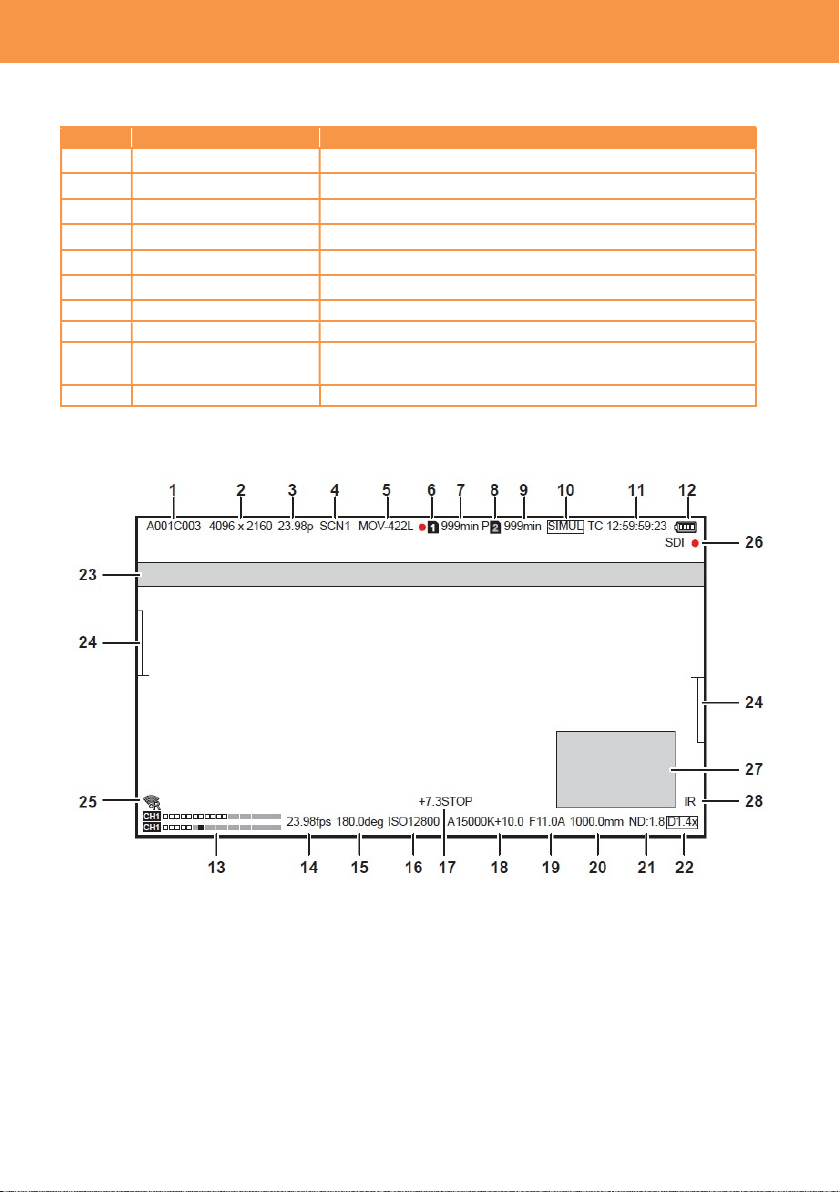
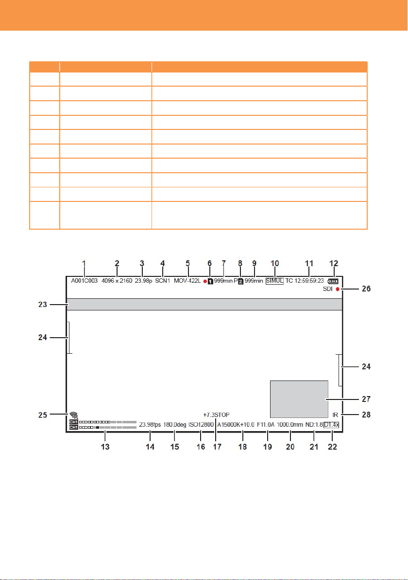
3-1-46. LCD INDICATOR
Camera status information to be shown on the LCD image can be set individually.
No. Menu item Description
1 CLIP NAME Clip name
2,3 PIXEL/FREQ System resolution and frequency for the main recorder
4 MAIN COLOR COLOR (Gamma & Gamut) for the main recorder
5 REC FORMAT Record codec for the main recorder
6,7,8,9
SLOT 1/2 STATUS Status of card slots, and remaining time
10 2 SLOTS FUNC
Current record mode of 2SLOT function (Relay or Simul)
11 TC Timecode, users bit, elapsed record time etc.
12 BATTERY REMAIN Remaining battery
26 REC REMOTE
Status of REC/PAUSE, for equipment connected to
SDI/HDMI OUTs.
13 AUDIO LEVEL METER
Audio level meter
Camera status information display on the LCD monitor
3. MENU settings (OUTPUT SETTINGS)
46
LCD INDICATOR (continued)
Camera status information to be shown on the LCD image can be set individually.
No. Menu item Description
14 FPS Frame rate in FPS
15 SHUTTER Shutter speed / open angle
16 EI Exposure index
18 WHITE Status of white balance adjustment
19,20
IRIS/ZOOM Zoom position and aperture level of the lens
21 ND FILTER ND filter position
22 E.I.S./D.ZOOM Status of Electric Image Stabilizer (EIS) and digital zoom
25 WLAN Connection status of Wi-Fi
28 IR SHOOTING Status of Infrared record mode
17 SPOT METER Measurement result of the spot meter in STOP / %
*The unit “STOP” can be selected in V-Log mode (MENU >
LCD EI ASSIST > SPOT METER UNIT item).
Camera status information display on the LCD monitor
3. MENU settings (OUTPUT SETTINGS)
47
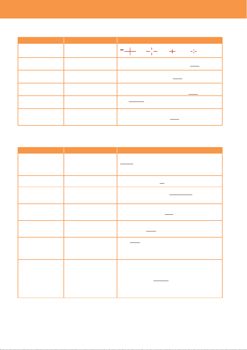
3-1-47. LCD MARKER
Marker characters to be shown on the LCD image can be set individually.
Menu item Description Value (factory default setting underlined)
CENTER
MARKER
Set shape of
center marker
1
2 3 4 OFF
SAFETY MARKER
Set the type of safety
zone marker.
1:Boxed, 2:Corner only, OFF
SAFETYAREA Set the size of safety
zone marker.
71.6%, 80%, 90%, 95%
FRAME MARKER
Set the type of frame
marker.
1.33:1, 1.44:1. 1.56:1, 1.78:1, 1.85:1, 2.00:1,
2.20:1, 2.35:1, 2.39:1, OFF
FRAME COLOR Set the color of frame
marker.
WHITE, BLACK, RED, GREEN, BLUE,
YELLOW
PLAYBACK
MARKER
Show marker
characters on the
playback image.
ON, OFF
3-1-48. LCD FOCUS ASSIST
Setting of focus assist related functions, available on the LCD monitor.
Menu item Description Value (factory default setting underlined)
EXPAND MODE Set image expanding
mode. It is assignable
to any USER buttons.
10SEC: Expand for 10 seconds
HOLD: Keep expanded until the button
pressed.
UNTIL REC: Expand until recording starts
EXPAND VALUE Set image magnifying
size.
x2, x3, x4
PEAK/SQUARES
MODE
Turn ON/OFF
peaking/square focus
assist function.
PEAKING, SQUARES,
PEAK/SQUARES
PEAKING LEVEL Set highlighting level
of peaking focus
assist.
LOW, MID, HIGH
PEAKING COLOR
Set highlighting color
of peaking focus
assist.
RED, GREEN, WHITE
BLACK & WHITE Turn ON/OFF
monochrome focus
assist function.
ON, OFF,
DURING PEAK.SQUARES: Cancel color on
the image while peaking/square focus assist
function is enabled.
OPEN IRIS MODE
Set activation time for
a focus assist function
that makes focusing
easier by opening
aperture (by making
depth of field
shallower).
10SEC, 30SEC
3. MENU settings (OUTPUT SETTINGS)
48
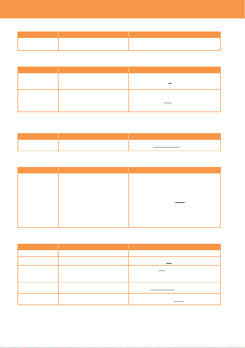
3-1-49. LCD EI ASSIST
Settings of Exposure index control related.
Menu item Description Value (factory default setting underlined)
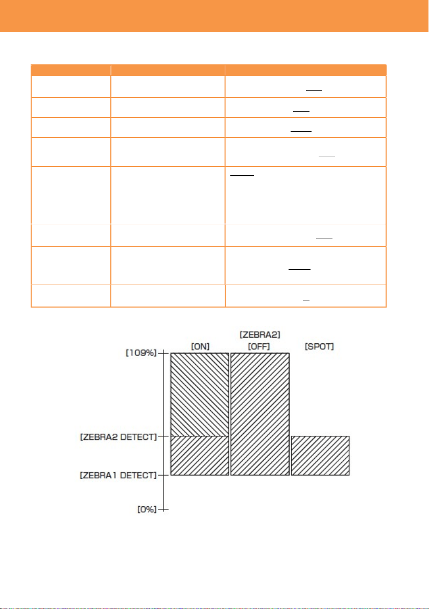
ZEBRA Turn ON/OFF the zebra
indicator on the LCD image.
ON, OFF
ZEBRA1 DETECT
Set the zebra pattern1.
(Right downward)
0% -- 80% -- 109%
ZEBRA2 DETECT
Set the zebra pattern2.
(Right upward)
0% -- 100% -- 109%
ZEBRA2 Set the type of light
indication. See figure 3-1
below for details.
ON, SPOT, OFF
WFM MODE Display waveform monitor or
vector scope. (User button
assignable)
WAVE: Display Waveform monitor (WFM)
VECTOR: Display vector scope (VSC)
WAVE/VECTOR:
Show WFM and VSC alternately by
pressing an USER button assigned the
function.
WFM
TRANSPARENT
Set transparency level of
WFM/VSC display.
0%, 25%, 50%
SPOT METER
UNIT
Set the unit of spot meter
display. “STOP” can be
selected only in V-Log
mode.
STOP, %
SPOT METER
SIZE
Set detection window size of
the spot meter.
S, M, L
Fig.3-1 ZEBRA indication
3. MENU settings (OUTPUT SETTINGS)
49
3-1-50. LCD LEVELGAUGE
Settings of level gauge to be displayed on the LCD image.
Menu item Description Value (factory default setting underlined)
LEVEL GAUGE
Turn ON/OFF level gauge
function.
ON, OFF
LEVEL GAUGE
RESET
Set the current horizontal and
vertical position as the
reference point for the level
gauge.
YES, NO
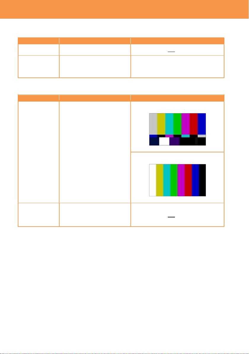
3-1-51. COLOR BARS
Menu item Description Value (factory default setting underlined)
COLOR BARS
TYPE
Set color bars type.
SMPTE
FULL
TEST TONE Turn ON/OFF 1KHz tone when
color bars pattern is turned
ON.
ON, OFF
3. MENU settings (OUTPUT SETTINGS)

50
3-1-52. SCENE FILE
Menu item Description
Value (factory default setting
underlined)
LOAD
Import custom scene files from the SD
memory card.
---
SAVE
Store custom scene files to the SD
memory card (overwrite to existing
files).
---
SAVE AS
Store custom scene files to the SD
memory card as a new file.
---
3-1-53. SETUP FILE
Menu item Description
Value (factory default setting
underlined)
LOAD
Import custom setup files from the SD
memory card.
---
SAVE
Store custom setup files to the SD
memory card (overwrite to existing
files).
---
SAVE AS
Store custom setup files to the SD
memory card as a new file.
---
3. MENU settings (FILE)

51
3-1-54. NETWORK SEL
Menu item Description Value (factory default setting underlined)
NETWORK SEL
Enable Wi-Fi mode.
*Require an optional Wi-Fi
adaptor.
WLAN, OFF
3-1-55. NETWORK FUNC
Menu item Description Value (factory default setting underlined)
USER
ACCOUNT
Set a user account information
for the Apple iPad app.
ADD, DELETE
3-1-56. NETWORK PROPERTY
Menu item Description Value (factory default setting underlined)
MAC ADDRESS
Display mac address
information of a Wi-Fi adaptor
connected.
---
TYPE Set a connection method. DIRECT
Connect to Wi-Fi devices such as a tablet
computer without using a wireless access
point.
INFRA(SELECT)
Connect to a wireless access point.
Access point can be chosen from an
available access point list.
INFRA(MANUAL)
Connect to a wireless access point.
Access point can be searched by entering
an SSID manually.
SSID
Display network name of the
AU-EVA1 unit.
---
BAND
Set connection type. (available
when TYPE item is set to
“DIRECT”)
2.4GHz, 5GHz
CHANNEL
(2.4GHz)
Set Wi-Fi channel of 2.4GHz
network.
AUTO, CH1, CH6, CH11
CHANNEL
(5GHz)
Set Wi-Fi channel of 5GHz
network.
AUTO, CH36, CH40, CH44, CH48,
CH100, CH104, CH108, CH112, CH116,
CH132, CH136, CH140, CH149, CH153,
CH157, CH161, CH165
ENCRYPTION
Set signal encryption method
for INFRA connection.
WPA-TKIP, WPA-AES, WPA2-TKIP,
WPA2-AES, NONE
ENCRYPT KEY
Set connection password.
------
*factory default password:
(01234567890123456789abcdef)
3. MENU settings (NETWORK SETTINGS)

52
NETWORK PROPERTY
(continued)
Menu item Description Value (factory default setting
underlined)
DHCP Set the IP address distribution
method using DHCP.
OFF: Do not use DHCP
CLIENT: Request the IP address to
external network device. Available in
INFRA(SELECT) or
INFRA(MANUAL) modes.
SERVER: Offer an IP address to a
device connected to the AU-EVA1.
IP ADDRESS Set an IP address. Available when
DHCP setting is set to “OFF” or
“SERVER”.
192.168.0.1
SUBNET MASK
Set subnet mask. Available when
DHCP setting is set to “OFF” or
“SERVER”.
255.255.255.0
DEFAULT
GATEWAY
Set default gateway. Available
when DHCP setting is set to “OFF”
or “SERVER”.
194.168.0.254
*Set to 0.0.0.0 when not in use.
PRIMARY DNS
Set Primly DNS server address.
Available when the TYPE item is
set to “INFRA(SELECT)” or
“INFRA(MANUAL)”, and DHCP
item is set to “OFF”.
0.0.0.0
SECONDARY
DNS
Set Secondary DNS server
address. Available when the TYPE
item is set to “INFRA(SELECT)” or
“INFRA(MANUAL)”, and DHCP
item is set to “OFF”.
0.0.0.0
3-1-57. CONNECTION HISTORY
Menu item Description Value (factory default setting underlined)
CONNECTION
HISTORY
Display connection history with
Wi-Fi access point.
SELECT, DELETE
3-1-58. NETWORK TOOLS
Menu item Description Value (factory default setting underlined)
INITIALIZE Restore network settings to
factory setting.
---
3. MENU settings (NETWORK SETTINGS)
53
*** This menu item is not available for AU-EVA1MC and AU-EVA1EJ models. ***
3-1-59. AREA SETTINGS
Menu item Description Value (factory default setting
underlined)
AREA
SETTINGS
Change certain menu items such as
DATE FORMAT, HEADROOM by
area setting. See the table below for
the details.
AREA1, AREA2, AREA3
Setting values by AREA SETTING
Menu item AREA1 AREA2 AREA3
DATE FORMAT
(*1)
Y-M-D M-D-Y D-M-Y
HEADROOM
20dB 20dB 18dB
3. MENU settings (OPTION メニュー)
MENU button
EXIT button

54
4. Understanding
advanced features
55
4-1. Understanding Variable Frame Rate (VFR) recording
How to use
1. Set following 3 items to use the VFR function in MENU > SYSTEM SETTINGS > SYSTEM
MODE. The maximum available frame rates (up to 60, 120, or 240fps) varies with the
“SENSOR MODE” menu item.
Menu item Description Value (factory default setting underlined)
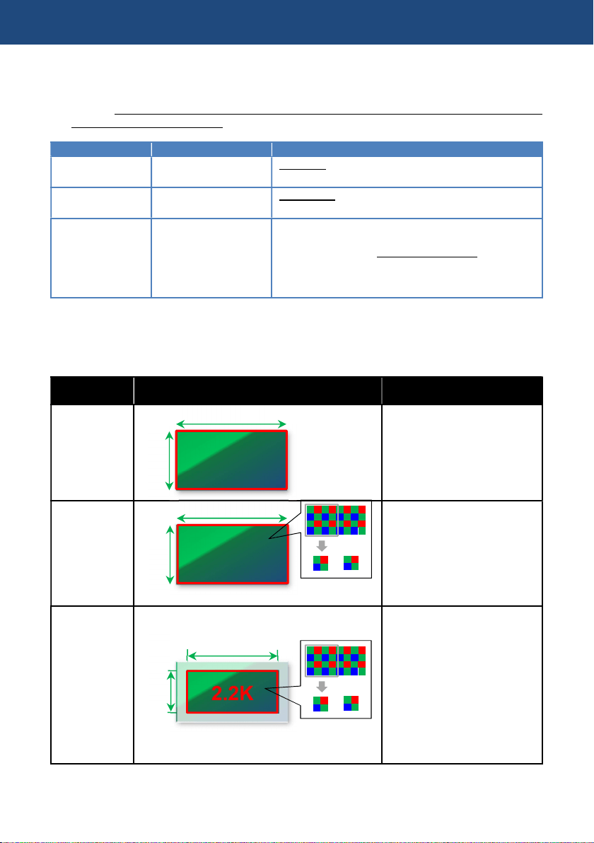
SENSOR MODE
Setting of the sensor
drive mode.
S35 5.7K, S35 MIX 2.8K, 4/3 CROP&MIX 2.2K
MAIN PIXEL Setting of the system
resolution.
4096x2160, 3840, 2160, 2048x1080, 1920x1080,
1280x720
MAIN CODEC Setting of the record
codec.
MOV
420LongGOP150M, 420LongGOP100M,
420LongGOP50M, 422LongGOP150M,
422LongGOP100M, 422LongGOP50M
AVCHD
AVCHD PS, AVCHD PH, AVCHD HA, AVCHD PM
2. Set CAMERA SETTINGS > FPS > VFR SW item to “ON”
3. Set frame rate with CAMERA SETTINGS > FPS > VALUE item.
4. Press REC button.
SENSOR MODE setting
SENSOR
MODE
Active area of image sensor Description
S35 5.7K
Use entire active plane of the
imager, and generate image
from all active pixels.
Max frame rate
60fps
S35 MIX2.8K
Use entire active plane of the
imager, and generate
2K/FHD image for horizontal
2.8K pixels by mixing pixels.
Max frame rate
120fps
4/3
CROP&MIX
2.2K
Use a part of the imager for
horizontal 2.2K pixels, and
generate 2K/FHD image by
mixing pixels.
Max frame rate
240fps
Angle of view becomes
narrower comparing with
S35 5.7K, and S35 MIX2.8K
modes
4. Understanding advanced features
24.596mm
5.7K
12.969m
24.596mm
2
.
8
K
12.969m
19.436mm
10.251mm
2.2
K
Pixel mix
Pixel mix
56
4-2. Monitoring image and recording
The AU-EVA1 has an HDMI 2.0 terminal and a 6G-SDI OUT, images can be output from these
terminals at the same time in different resolutions. The same content display with LCD MONITOR
available on the SDI OUT as the LCD crone display function.
Different image color (Gamma & Gamut preset) can individually be assigned to each output (HDMI,
SDI, and LCD).
Setting SDI OUT
1. MENU > SYSTEM SETTINGS > SYSTEM MODE > FREQUENCY and MAIN PIXEL
2. MENU > OUTPUT SETTINGS > SDI OUT > SIGNAL SEL and OUT FORMAT
*See 6-3. Output signals (SDI and HDMI) (P.74) for details
Setting HDMI OUT
1. MENU > SYSTEM SETTINGS > SYSTEM MODE > FREQUENCY and MAIN PIXEL
2. MENU > OUTPUT SETTINGS > HDMI OUT > OUT FORMAT
*See 6-3. Output signals (SDI and HDMI) (P.74) for details
4. Understanding advanced features
4K60p 4:2:2 10-bit support
REC remote function
Character superimpose
6G
-
SDI
OUT
2.0 OUT
4K30p 4:2:2 10-bit support
REC remote function
Same content display with LCD monitor
LCD MONITOR
3.5 inch LCD monitor with focus assist,
and EI assist function. Touch screen.
Image resolution of HDMI and SDI OUT signals vary depend on the system settings.
See 6-3. Output signals (SDI and HDMI) (P.74) for the details.
57
4-3. Understanding focus assist modes
The AU-EVA1 has five different focus assist modes, they can be individually recalled with USER
assignable buttons (except for monochrome focus assist mode).
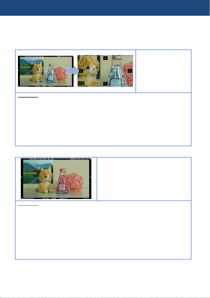
EXPAND
Part of image can be
magnified up to 4 times
(x2, x3, x4)
Its magnification period
can be set from 3 different
patterns below.
How to use
1. Assign “EXPAND” to one of the USER buttons. (USER 8 in factory default)
2. Set the power in MENU > OUTPUT SETTINGS > LCD FOCUS ASSIST > EXPAND VALUE
[x2] [x3] [x4]
3. Set magnification period in MENU > OUTPUT SETTINGS > LCD FOCUS ASSIST >
EXPAND MODE
[10SEC] Magnify for 10 seconds, and return to x1 after that.
[HOLD] Keep magnified until the function is recalled with the USER button is pressed.
[UNTIL REC] Keep magnified until recording starts.
4. Press the “USER” button assigned the function.
PEAKING
Adding colored highlights to in-focus edges.
Highlighting level can be adjusted, and its color
can also be selected from four different colors.
It can be used in combination with “SQUARE”
focus assist mode.
How to use
1. Assign “PEAK./SQUARES F.A.” to one of the USER buttons. (USER 2 in factory default)
2. Set [PEAKING] or [PEAK/SQUARE] in MENU > OUTPUT SETTINGS > LCD FOCUS
ASSIST > PEAK./SQUARES F.A.
3. Adjust its highlighting level.
MENU > OUTPUT SETTINGS > LCD FOCUS ASSIST > PEAKING LEVEL
4. Select its highlighting color
MENU > OUTPUT SETTINGS > LCD FOCUS ASSIST > PEAKING COLOR > RED,
GREEN, WHITE
5. Press the “USER” button assigned the function.
4. Understanding advanced features
58
4-3. Understanding focus assist feature (continued)
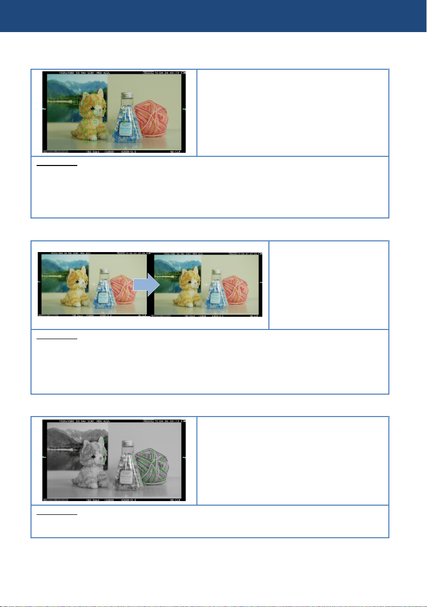
FOCUS SQUARE
Green square boxes are displayed on the
viewfinder image, whose size increases as the
object behind the box comes into focus. Adjust
focus ring/control so that size of the boxes over
the subject/area of interest become maximum.
It can be used in combination with “PEAKING”
focus assist mode.
How to use
1. Assign “PEAK./SQUARES F.A.” to one of the USER buttons. (USER 2 in factory default)
2. Set [SQUARES] or [PEAK./SQUARES] in MENU > OUTPUT SETTINGS > LCD FOCUS
ASSIST > PEAK./SQUARES F.A.
3. Press the “USER” button assigned the function.
OPEN IRIS
Makes focusing easier by
opening aperture (i.e. by
making depth of field
shallower). Brightness of the
image is maintained even
when aperture is opened
with automatic shutter
speed control.
How to use
1. Assign “OPEN IRIS F.A.” to one of the USER buttons. (USER 9 in factory default)
2. Set the activation time in MENU > OUTPUT SETTINGS > LCD FOCUS ASSIST > OPEN
IRIS MODE > 10SEC , 30SEC
3. Press the “USER” button assigned the function.
MONOCHROME
Makes focusing easier by canceling
chrominance component on the viewfinder
image.
How to use
1. MENU > OUTPUT SETTINGS > LCD FOCUS ASSIST > BLACK&WHITE > ON
4. Understanding advanced features
59
4-4. Understanding sport meter as Exposure Index (EI) assist
Measuring video level and stop settings to achieve desired exposure, can be performed easily with
the SPOT METER function.
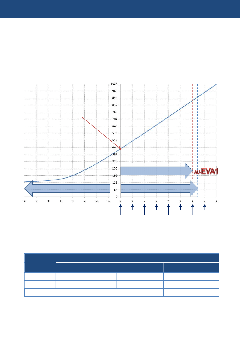
Overwiew
The graph on the figure 4-1 shows the AU-EVA1’s V-Log gamma curve. It is designed to have the
same characteristic as the original VARICAM’s (35 and LT) curve hense, LUTs developed for
VARICAM series can also be used for the AU-EVA1’s footage, Please note that EVA1 exposure
latitude is 14 stop while VARICAM35/LT is 14.5 stops..
Fig.4-1 AU-EVA1’s V-Log curve
10-bit code value of gray with reflection of 18% is defined as 433 (42% in IRE).
Input
reflection
[%]
V-Log
IRE [%] 10bit Code value 12bit Code value
0 7.3 128 512
18 42 433 1732
90 61 602 2408
4. Understanding advanced features
+6 Stops
-8 Stops
VARICAM
+6.5 Stops
18% Gray
18%
36%
72%
144%
288%
576%
1152%
2304%

60
4-4. Using sport meter as Exposure Index (EI) assist
Adjusting EI with percent (%) display (example)
1. Set display unit of the spot meter function.
MENU > OUTPUT SETTINGS > LCD EI ASSIST > SPOT METER UNIT > %
2. Recall the function with one of the USER buttons (USER3 in the factory setting).
3. Position the sampling box (displayed in center of the viewfinder image) over the subject to be
measured (18% gray reference for example).
4. Set the aperture, ISO, Frame rate (fps), and shutter so that the level shown on the spot meter
is 42% in “V-Log” and “V-255570L1” gamma modes, or 45% in “V-504580L1”.
Adjusting EI with STOP display (example)
1. Set display unit of the spot meter function with the menu item below.
MENU > OUTPUT SETTINGS > LCD EI ASSIST > SPOT METER UNIT > SPOT
2. Recall the function with one of the USER buttons (USER3 in the factory setting).
3. Position the sampling box (displayed in center of the viewfinder image) over the subject to be
measured (18% gray reference for example).
4. Set the aperture, ISO, Frame rate (fps), and shutter so that the level shown on the spot meter
is 0.0STOP.
NOTE
* See 2-4. User assignable buttons (P.18) how to assign functions to USER buttons.
* Size of the box (zone for measurement) can be changed in MENU > OUTPUT SETTINGS
> LCD EI ASSIST > SPOT METER SIZE> S, M, L
4. Understanding advanced features
61
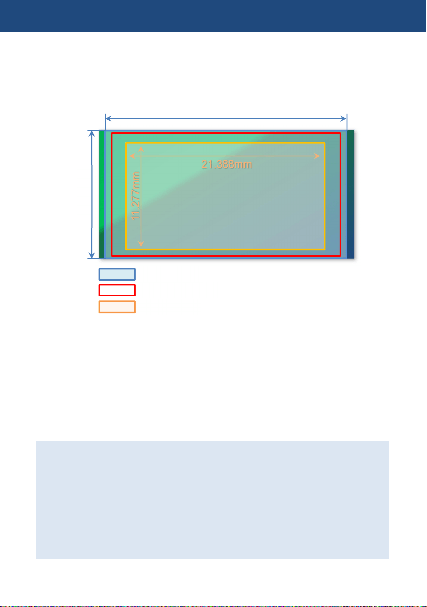
4-5. Understanding Electric Image Stabilizer (EIS) function
The AU-EVA1 is equipped with an image stabilization function that works electrically with
assistance of built-in gyro sensors. The following figure illustrates the effective area of the function,
and the area for motion detection and stabilizing (which is wider than the normal Super35 image
area). The area to be recorded is cropped as 1/1.15 of the Super35 area.
How to use
EIS related settings are in MENU > CAMERA SETTINGS > E.I.S
1. Select a way to set focal length information which is used for the reference in MENU >
CAMERA SETTINGS > E.I.S > ZOOM POSITION DATA > AUTO / MANUAL.
* EF lenses that can provide focal length information to the camera are needed for AUTO
detection.
2. When the ZOOM POSITION DATA item is set to “MANUAL”, focal length setting can be set
from 8mm to 200mm.
3. Enable the EIS function with one of the USER buttons (USER4 for the factory setting).
Note:
・ Effect level becomes smaller as the frame rate decreases lower than 24fps in variable
frame rate mode (see. 4-1. Understanding Variable Frame Rate (VFR) recording).
・ No enough effect can be expected with the lenses whose focal length is outside the range
of 8mm to 200mm.
・ EIS does not function under following conditions:
When the sensor mode (MENU > SYSTEM SETTINGS > SYSTEM MODE > SENSOR
MODE) menu item is set to “4/3CROP&MIX2.2K”.
While digital zoom (D.ZOOM) is functioning.
While optical image stabilizer is working in the lens.
4. Understanding advanced features
11.277mm
21.388mm
25.697mm
13.588
mm
Super35 image area
EIS active area
Recorded area
62
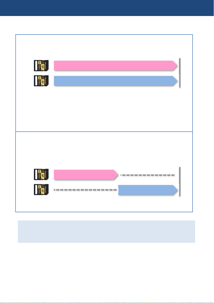
4-6. Understanding dual memory card slot feature
SIMUL (Simultaneous)
Record the same content onto two SD memory cards simultaneously. Even if recording stops on
one card unexpectedly, recording on the other card can continue.
・ In the case when one of the cards (in slot1 for example) becomes full and stops
recording, recording also stops on another card (in slot2). To recover that, replace an SD
memory card that stopped initially (slot1) and press REC button. If just pressed REC
button without replacing any card, recording resumes with a card (in slot2).
・ Use the same SD memory card type for speed class and capacity. Using different
specification of the card may cause unexpected recording to stop.
RELAY
Recording is taken over from one to the other card. Suitable for long-duration recordings. Even
if the camera is in recording, one of other card (which is not in recording) can be ejected and
another mounted.
*The maximum continuous record time is 10 hours.
Using the Two-slot features.
MENU > REC SETTINGS > 2SLOT FUNC. > SIMUL REC, RELAY REC
4. Understanding advanced features
Record
Record
Record
Record
63
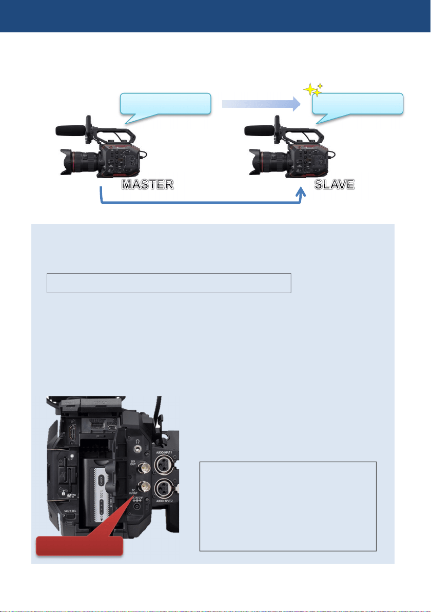
4-7. Synchronize timecode
The AU-EVA1 has a timecode IN/OUT terminal (common use for IN and OUT). The following
describes workflow know-how when using timecode synchronization feature with two AU-EVA1.
Preparation
1. Connect TC IN/OUT terminals on both master and slave units with a BNC cable.
2. Make sure that the settings of the following menu item is the same for both units.
SYSTEM SETTINGS > SYSTEM MODE > FREQUENCY
Setting for master unit
4. Set MENU > REC SETTINGS > TC > TC IN/OUT SEL item to “TC OUT”.
5. Set MENU > REC SETTINGS > TC > DF/NDF item to “DF” or “NDF (*1)”.
*1 Selectable when FREQUENCY setting is 23.98p, 24.00p, 25.00p, 50.00p, or 50.00i.
Setting for slave unit
1. Set MENU > REC SETTINGS > TC > FREE/REC RUN item to “FREE RUN”.
2. Set MENU > REC SETTINGS > TC > TC IN/OUT SEL item to “TC IN”.
4. Understanding advanced features
Synchronize
TCG 01:20:0
0
:
20
TCG 01:20:0
0
:
20
TC IN/OUT terminal
NOTE:
Since the AU-EVA1 does not have genlock
feature, timecode values may differ for 1
frame from the value supplied.
The AU-EVA1 locks timecode value while
the unit is in REC stand-by mode. Does not
lock while in recording mode.
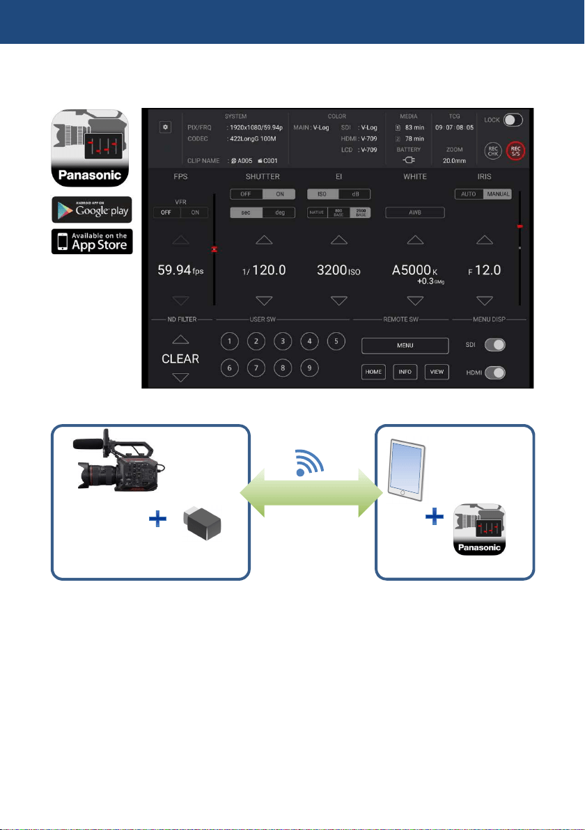
64
4-8. Understanding remote operation via EVA ROP application
Remote control via Wi-Fi network is available by using an application for iPad and Android OS.
Necessary equipment
Setting up equipment (Overview)
1. Install the Panasonic EVA ROP application from Apple App Store or Google Play to the tablet
device.
2. Connect the wireless module to the USB2.0 HOST terminal on the AU-EVA1.
3. Set Wi-Fi related settings on the AU-EVA1.
4. Set Wi-Fi related settings on the tablet device and connect to the AU-EVA1.
5. Open the Panasonic EVA ROP application.
4. Understanding advanced features
Wireless module
iPad
/Android
tablet device
EVA ROP application
AU
-
EVA1
Panasonic AJ-WM50 etc.
Wi
-
Fi connection

65
Set up example
Setting on AU-EVA1
1. Connect a wireless module (optional) to the USB2.0 HOST terminal.
2. Set following USB related menu items to enable the USB port for EVA ROP connection.
MENU > NETWORK SETTINGS > NETWORK SEL > WLAN
3. Set network related menu items in MENU > NETWORK SETTINGS > NETWORK PROPERTY.
Menu item
Value
TYPE
DIRECT
SSID
Enter SSID name (Default: AU-EVA1)
BAND
Choose “
2
.4GHz
” or “
5GHz
” depends on Wi-Fi adaptor type.
CHANNEL(2.4GHz)
AUTO
CHANNEL(5GHz)
AUTO
ENCRYPT KEY
Enter connection password used to connect to the AU-EVA1 from
the tablet device. (Default: 01234567890123456789abcdef)
DHCP
SERVER
IP ADDRESS
Default:192.168.0.1
SUBNET MASK
Default:255.255.255.0
DEFAULT GATEWAY
Default:192.168.0.254
4. Set an account in MENU > NETWORK SETTINGS > NETWORK FUNK
Menu item
Value
USER ACCOUNT
Set an account (ID name and its password) used for
authentication from EVA ROP.
(Default ID: guest , password: auguest)
4. Understanding advanced features
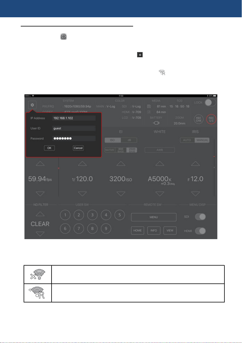
66
Setting on tablet device (on iPad for example)
1. Install the Panasonic EVA ROP app from App Store.
2. Open “Setting” > Wi-Fi > “, and choose an SSID of the AU-EVA1 (example AU-EVA1).
3. Enter connection password (factory default: 01234567890123456789abcdef) to connect to the
AU-EVA1 via Wi-Fi network.
4. Open the Panasonic EVA ROP app on the iPad. Tap symbol and complete authentication
settings by entering "IP address, user ID (factory setting: guest), and password (factory setting:
auguest) of the AU-EVA1.
5. Confirm that the connection status of the AU-EVA1 is shown as (ready to be controlled
from the app.).
6. Start operation from the app.
Panasonic EVA ROP application for iPad
Connection status on the AU-EVA1
No connection
Connected to a Wi-Fi device (iPad/Android device, Wi-Fi access point etc.)
4. Understanding advanced features

67
5. File format
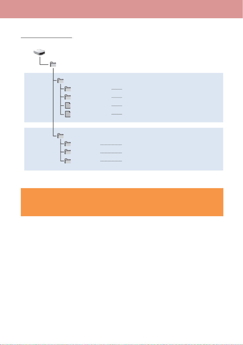
68
5-1. Folder structure in the record media
Folder structure example
Caution
Several kind of different files are stored under PRIVATE folder. Always copy the PRIVATE
folder as a file set. Copying .MTS, .MOV files only may cause clip to be unplayable.
5. File format
Video data (
4K 59.94p, LPCM
audio)
Video data (UHD 29.97p, LPCM audio)
For file management
For file management
Thumbnail data
Video data (.MTS format)
For file management
PRIVATE
PANA_GRP
001QAQAM
002RCQAM
BACKUP.TMP
INDEX.DAT
SD
card volume
AVCHD
AVCHDTN
BDMV
PANA_EXT
MOV
clips
AVCHD
clips
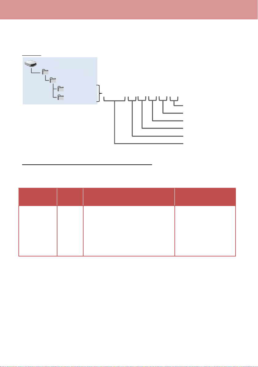
69
5-2. Folder name (MOV format)
Folders storing MOV clips are named depends on resolution, frame rate, video format, and other
settings below.
Example
Example: a folder is named as “001QAQAM”
This folder contains clips with 4096x2160 resolution, 59.94fps frame rate, and MOV, LPCM format
in progressive scan mode.
Resolution
Frame
rate
(fps)
Scan mode Record mode
Q:4096x2160
R:3840x 2160
P:2048x1080
Y:1920x1080
A: 59.94
B: 50.00
C: 29.97
D: 25.00
E: 24.00
F: 23.98
Q:Progressive scan (with LPCM audio)
J:Interlace scan (with LPCM audio)
T: Simul record mode
M: Normal record mode
PRIVATE
PANA_GRP
001QAQAM
002RCQAM
B002
5. File format
001QAQAM
Record mode
Fixed
Scan mode
Frame rate
Resolution
File number (incremental)
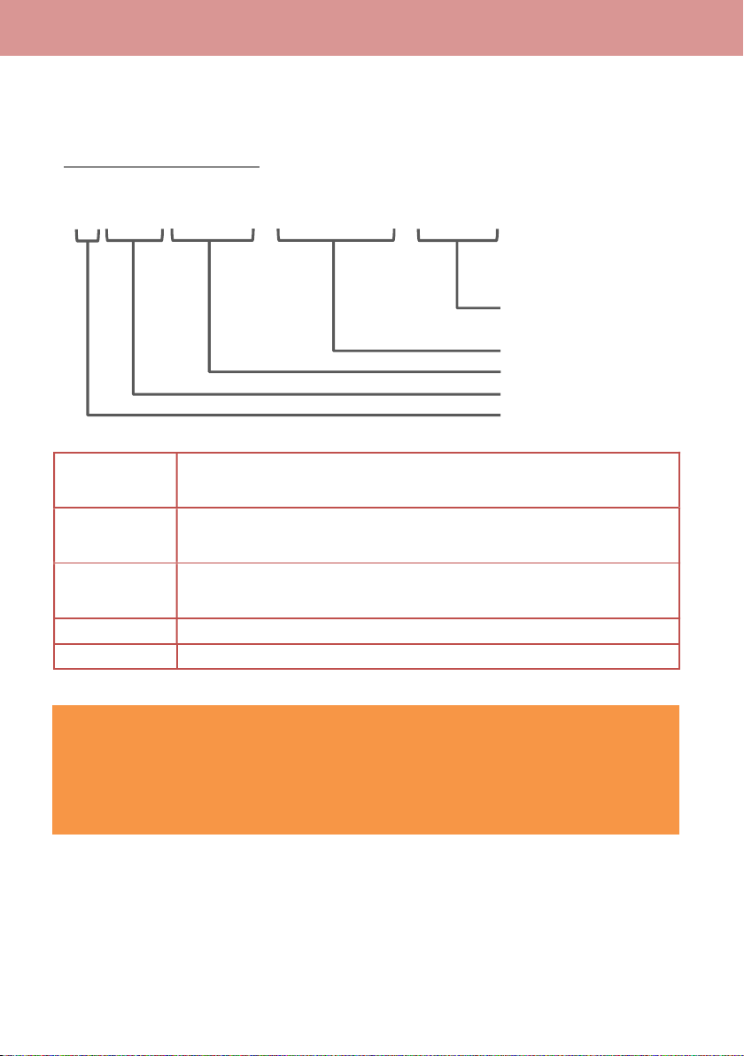
70
5-3. File name (MOV format)
The AU-EVA1 supports 20-digits cine style clip naming for MOV clips as the same structure with
VARICAM series (AU-V35LT1G etc.) for easy clip management.
Example of cine style file name
Camera index
(A to Z)
It can be assigned in MENU > REC SETTINGS > CLIP NAME > CAM
INDEX.
Reel number
(001 to 999)
Increments by SD memory card, the three digits index is named as SD card’s
volume label.
Clip number
(C001 to C999)
Increments by recording. Its number count returns to C001 when format a SD
card. Its number incrementing goes on even when folder is separated.
Date
yymmdd format
Unique ID
Numbers and alphabets, four letters in total
Caution
・ In the SIMUL (simultaneous) record mode, the same clip name is given to the SD card in the
both slot1 and slot2.
・ The maximum number of recordable clips in a folder is 999.
・ The maximum number of recordable clips in an SD card is approximately 4000 clips.
5. File format
B0
0
2C 010
-
170 9 18
-
E1 25 .m o v
Date (yymmdd)
Clip number (C001 - C999)
Reel number (001 - 999)
Camera index (A-Z)
Unique ID generated from
serial number of
each unit

71
6. Appendix
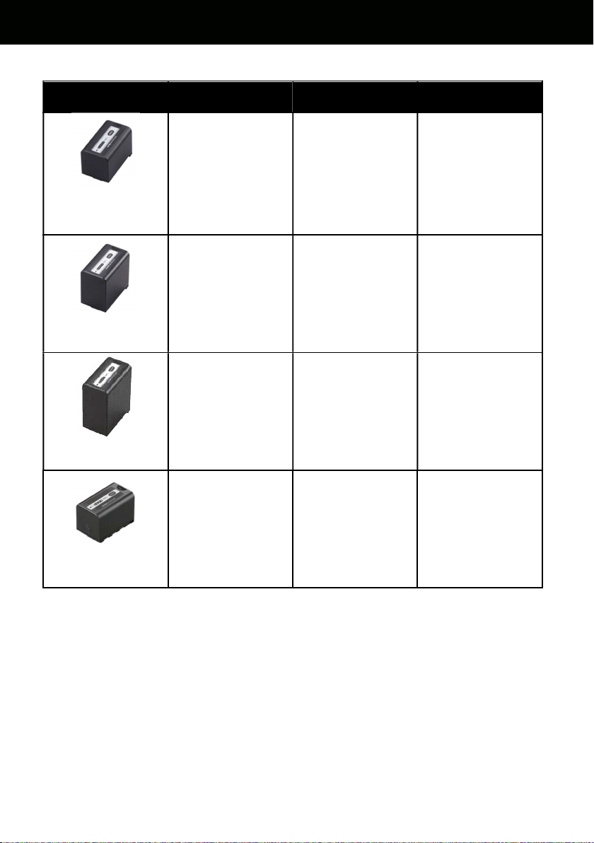
72
6-1. Battery runtime
Part number
Voltage & capacity
(Minimum)
Hours to charge
*1
Operation time
*2
VW-VBR59
(comes
standard/optional)
7.28V
5900mAh, 43Wh
3h 20min 2h 50min
VW-VBR89G
(Optional)
7.28V
8850mAh, 64Wh
4h 00min 4h 15min
VW-VBR118G
(Optional)
7.28V
11800mAh, 86Wh
4h 40min 5h 40min
VW-VBD58
(Optional)
7.2V
5800mAh, 42Wh
5h 20min 2h 40min
*1 Charging times are measured at an ambient temperature of 25°C / 77.0°F, and relative humidity
at 60%, using the battery charger that comes standard with product. N.B. it may vary under
different conditions.
*2 Operation times are measured under following conditions, Times may vary under different
conditions.
・ Menu settings, factory default.
・ Remote operation grip connected, no any other cables are connected to any IN/OUT terminals.
6. Appendix
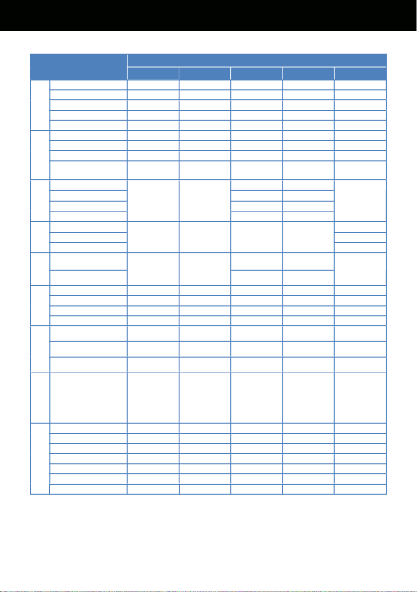
73
6-2. Scene file preset
Menu item
MAIN
SCENE1 SCENE2 SCENE3 SCENE4 SCENE5
BLACK
M.PED 0 2 8 8 1
R PED 0 0 0 0 0
G PED 0 0 0 0 0
B PED 0 0 0 0 0
PEDESTAL OFFSET
OFF OFF OFF OFF OFF
GAMMA
GAMMA SELECT V255570L1
V504580L1
VIDEO VIDEO HLG
MASTER GAMMA
*1 *1 0.45 0.50 *1
BLACK GAMMA *2 *2 OFF OFF OFF
B.GAMMA
RANGE
*2 *2 1 1
1
KNEE
KNEE SW
*1 *1
ON ON
*1
KNEE MODE D RANGE
D RANGE
KNEE POINT 90% 93%
KNEE SLOPE 100 100
HLG
KNEE
KNEE SW
*3 *3 *3 *3
OFF
KNEE POINT 55
KNEE SLOPE 10
WHITE
CLIP
SW
*1 *1
OFF OFF
*1
LEVEL 109% 109%
DETAIL
SW OFF OFF ON ON OFF
CORING 0 0 0 0 0
MASTER LEVEL 0 0 0 0 0
FREQUENCY 1 1 1 1 1
SKIN
DETAIL
SKIN DTL1 OFF OFF OFF OFF OFF
SKIN DTL2 OFF OFF OFF OFF OFF
SKIN DTL3 OFF OFF OFF OFF OFF
CHROMA
LEVEL 0% 0% 0% 15% 0%
MATRIX
SW OFF OFF OFF OFF OFF
(R-G) 0 0 0 0 0
(R-B) 0 0 0 0 0
(G-R) 0 0 0 0 0
(G-B) 0 0 0 0 0
(B-R) 0 0 0 0 0
(B-G) 0 0 0 0 0
*1 Available when GAMMA SELECT setting is set to “VIDEO”.
*2 Available when GAMMA SELECT setting is set to “VIDEO” or “HLG”.
*3 Available when GAMMA SELECT setting is set to “HLG”.
6. Appendix
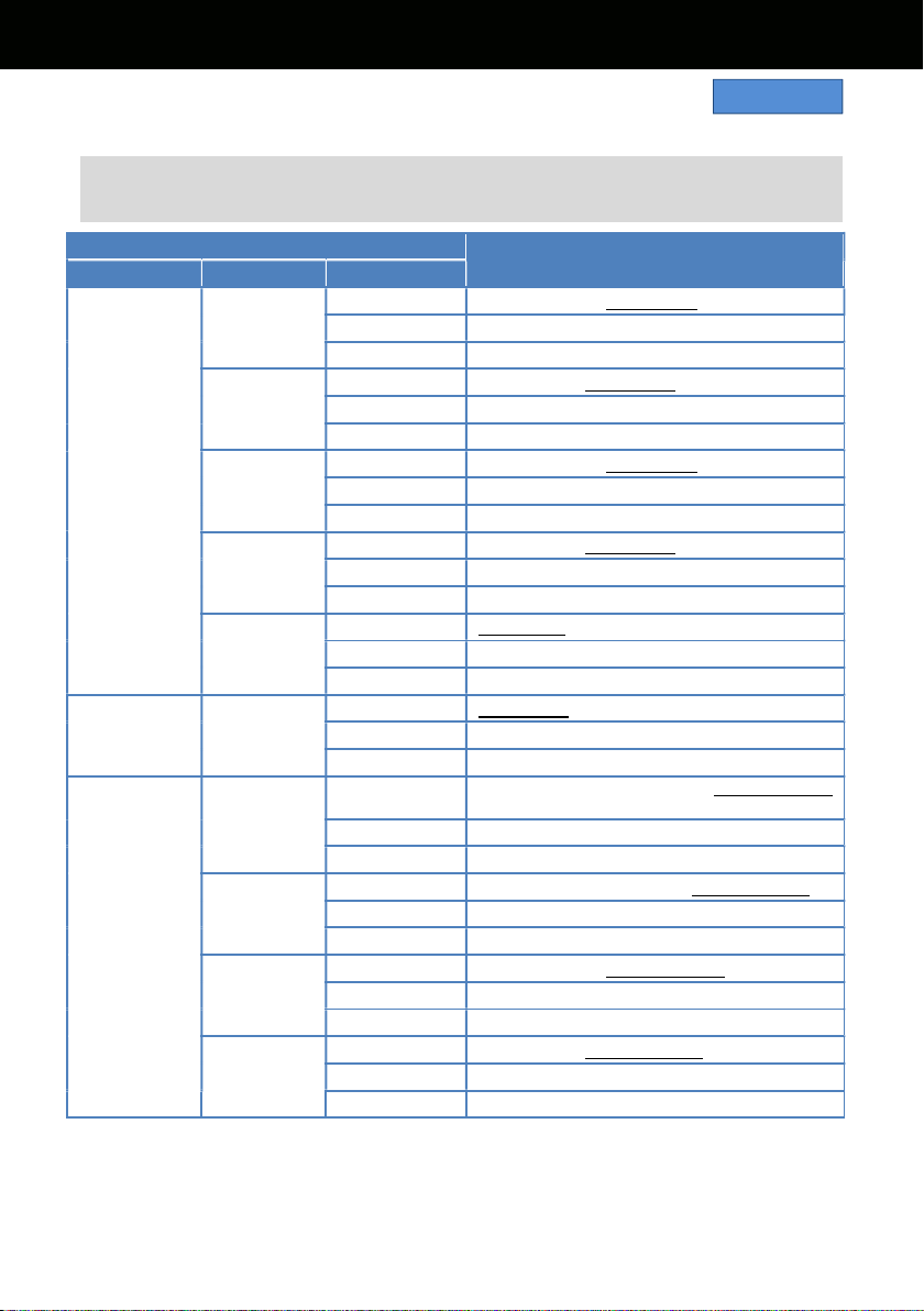
74
6-3. Output signals (SDI and HDMI)
Image resolution of SDI OUT signal varies depends on the combination of settings below.
MENU > SYSTEM SETTINGS > SYSTEM MODE > FREQUENCY and MAIN PIXEL
MENU > OUTPUT SETTINGS > SDI OUT > SIGNAL SEL and OUT FORMAT
MENU SETTING
SIGNAL OUT FORMAT
(OUT FORMAT MENU ITEM)
FREQUENCY
MAIN PIXEL
SIGNAL SEL
59.94p
50.00p
4096x2160
SDI 1920x1080p *1, 1920x1080i *1
LCD (1080p) 1920x1080p *2
LCD (1080i) 1920x1080i *2
3840x2160
SDI 1920x1080p, 1920x1080i
LCD (1080p) 1920x1080p *2
LCD (1080i) 1920x1080i *2
2048x1080
SDI 1920x1080p *1, 1920x1080i *1
LCD (1080p) 1920x1080p *2
LCD (1080i) 1920x1080i *2
1920x1080
SDI 1920x1080p, 1920x1080i
LCD (1080p) 1920x1080p *2
LCD (1080i) 1920x1080i *2
1280x720
SDI 1280x720p
LCD (1080p) 1920x1080p *2
LCD (1080i) 1920x1080i *2
59.94i
50.00i
1920x1080
SDI 1920x1080i
LCD (1080p) 1920x1080p *2
LCD (1080i) 1920x1080i *2
29.97p
23.98p
4096x2160
SDI
4096x2160p, 1920x1080p *1, 1920x1080PsF
*1
LCD (1080p) 1920x1080 over 59p *2
LCD (1080i) 1920x1080 over 59i *2
3840x2160
SDI 3840x2160p, 1920x1080p, 1920x1080PsF
LCD (1080p) 1920x1080 over 59p *2
LCD (1080i) 1920x1080 over 59i *2
2048x1080
SDI 1920x1080p *1, 1920x1080PsF *1
LCD (1080p) 1920x1080 over 59p *2
LCD (1080i) 1920x1080 over 59i *2
1920x1080
SDI 1920x1080p, 1920x1080PsF
LCD (1080p) 1920x1080 over 59p *2
LCD (1080i) 1920x1080 over 59i *2
*1 Displayed as letterbox format, image quality may slightly be lower than image recorded.
*2 LCD clone mode, focus and EI assist characters can be displayed, image sampling and bit-depth
becomes 4:2:2 8-bit, blank panels (at top, bottom, left, and right) are always displayed.
6. Appendix
SDI OUT
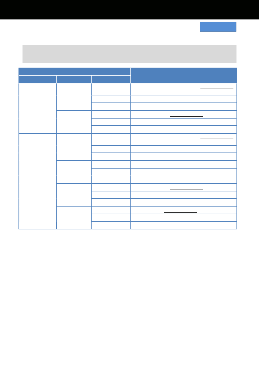
75
6-3. Output signals (SDI and HDMI)
Image resolution of SDI OUT signal varies depends on the combination of settings below.
MENU > SYSTEM SETTINGS > SYSTEM MODE > FREQUENCY and MAIN PIXEL
MENU > OUTPUT SETTINGS > SDI OUT > SIGNAL SEL and OUT FORMAT
MENU SETTING
SIGNAL OUT FORMAT
(OUT FORMAT MENU ITEM)
FREQUENCY
MAIN PIXEL
SIGNAL SEL
24.00p
4096x2160
SDI
4096x2160p, 1920x1080p *1, 1920x1080PsF
*1
LCD (1080p) 1920x1080 over 60p *2
LCD (1080i) 1920x1080 over 60i *2
2048x1080
SDI 1920x1080p *1, 1920x1080PsF *1
LCD (1080p) 1920x1080 over 60p *2
LCD (1080i) 1920x1080 over 60i *2
25.00p
4096x2160
SDI
4096x2160p, 1920x1080p *1, 1920x1080PsF
*1
LCD (1080p) 1920x1080 over 50p *2
LCD (1080i) 1920x1080 over 50i *2
3840x2160
SDI 3840x2160p, 1920x1080p, 1920x1080PsF
LCD (1080p) 1920x1080 over 50p *2
LCD (1080i) 1920x1080 over 50i *2
2048x1080
SDI 1920x1080p *1, 1920x1080PsF *1
LCD (1080p) 1920x1080 over 50p *2
LCD (1080i) 1920x1080 over 50i *2
1920x1080
SDI 1920x1080p, 1920x1080PsF
LCD (1080p) 1920x1080 over 50p *2
LCD (1080i) 1920x1080 over 50i *2
*1 Displayed as letterbox format, image quality may slightly be lower than image recorded.
*2 LCD clone mode, focus and EI assist characters can be displayed, image sampling and bit-depth
becomes 4:2:2 8-bit, blank panels (at top, bottom, left, and right) are always displayed.
6. Appendix
SDI OUT
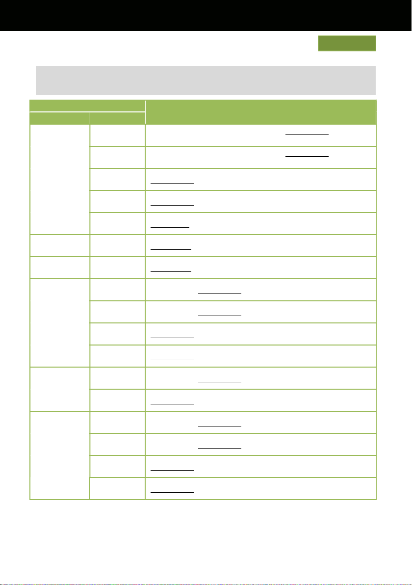
76
6-3. Output signals (SDI and HDMI)
Image resolution of HDMI OUT signal varies depends on the combination of settings below.
MENU > SYSTEM SETTINGS > SYSTEM MODE > FREQUENCY and MAIN PIXEL
MENU > OUTPUT SETTINGS > HDMI OUT > OUT FORMAT
MENU SETTINGS
SIGNAL OUT FORMAT
(OUT FORMAT MENU ITEM)
FREQUENCY
MAIN PIXEL
59.94p
50.00p
4096x2160
4096x2160p, 4096x2160p (4:2:0 8bit), 1920x1080p *3,
1920x1080i *3
3840x2160
3840x2160p, 3840x2160p (4:2:0 8bit), 1920x1080p,
1920x1080i
2048x1080
1920x1080p *3, 1920x1080i *3
1920x1080
1920x1080p, 1920x1080i
1280x720 1280x720p
59.94i 1920x1080
1920x1080i, 720x480p
50.00i 1920x1080
1920x1080i, 720x576p
29.97p
23.98p
4096x2160
4096x2160p, 1920x1080p *3
3840x2160
3840x2160p, 1920x1080p
2048x1080
1920x1080p *3
1920x1080
1920x1080p
24.00p
4096x2160
4096x2160p, 1920x1080p *3
2048x1080
1920x1080p *3
25.00p
4096x2160
4096x2160p, 1920x1080p *3
3840x2160
3840x2160p, 1920x1080p
2048x1080
1920x1080p *3
1920x1080
1920x1080p
*3 Displayed as letterbox format, image quality may slightly be lower than image for record.
6. Appendix
HDMI OUT
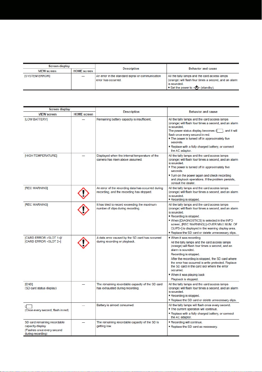
77
6-4. Error and warning system
When the AU-EVA1 detects any error or system trouble, the camera alearts is indicated on the LCD
monitor (HOME and VIEW screen), and the tally lamp.
SYSTEM ERROR
WARNING
6. Appendix
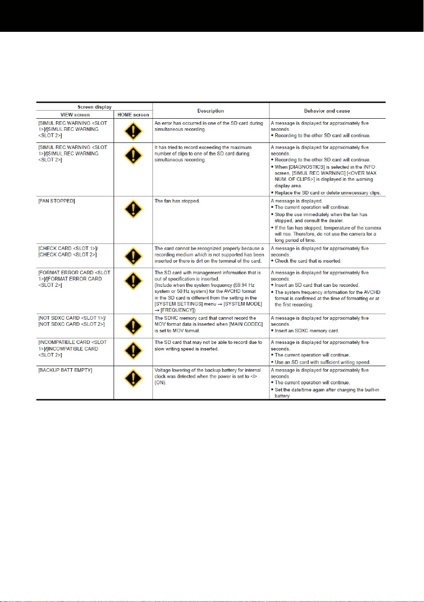
78
6-4. Error and warning system
When the AU-EVA1 detects any error or system trouble, the camera alearts is indicated on the LCD
monitor (HOME and VIEW screen), and the tally lamp.
ALERT
6. Appendix
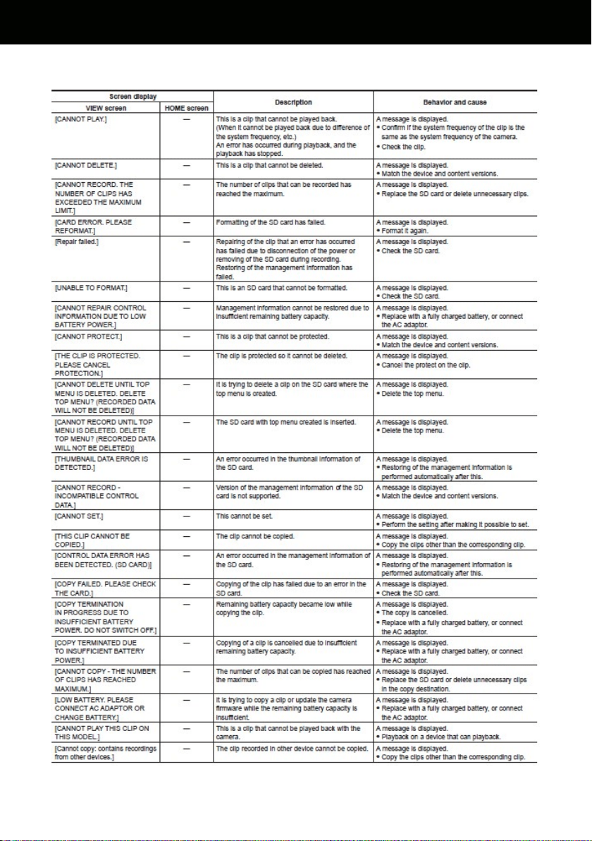
79
6-4. Error and warning system
MESSAGE
6. Appendix
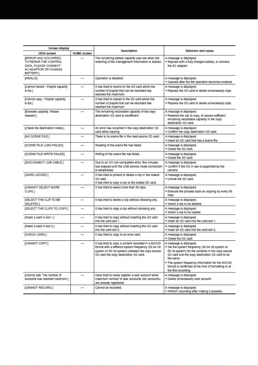
80
6-4. Error and warning system
MESSAGE
6. Appendix
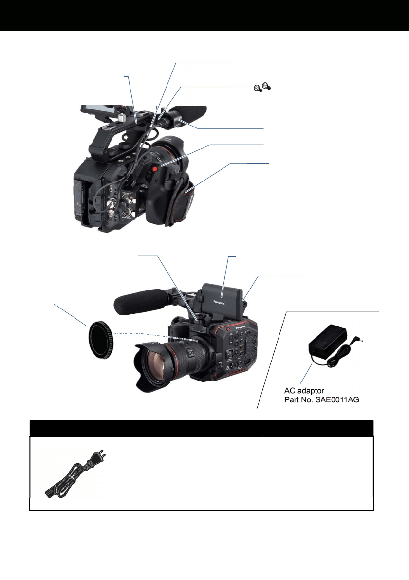
81
6-5. Genuine accessories
AC power cord
Part No.
K2CA2YY00259 for AU-EVA1P, PJ
K2CA2YY00129 for AU-EVA1PX
K2CR2YY00026 for AU-EVA1AN
K2CQ2YY00117 for AU-EVA1EJ, EN
K2CT2YY00095 for AU-EVA1EJ
K2CP2YY00083 for AU-EVA1ED
K2CA2YY00130 for AU-EVA1MC
(C type plug)
(BF type plug)
* Part number and design are subject to change without notice.
6. Appendix
Grip, Part No. 2YM2AUEVA1Z
Mic-holder, Part No. VYC1146
Mic-holder mounting screes
(12mm in length)
Part No. VYC1144 (2pcs.)
Grip belt, Part No. VFC5098
Mic-holder adaptor (with 1x 6mm screw)
Part No. 1KP1AUEVA1Z
LCD monitor, Part No. 3YM1AUEVA1Z
LCD monitor mounting bracket
Part No. 9YE2AUEVA1Z
LCD monitor hood
Part No. 1KV1AUEVA1Z
Carrying handle
Part No. 1KH1AUEVA1Z
Lens mount cap
Part No. DVGX1120ZK
AC adaptor
Part No. SAE0011AG
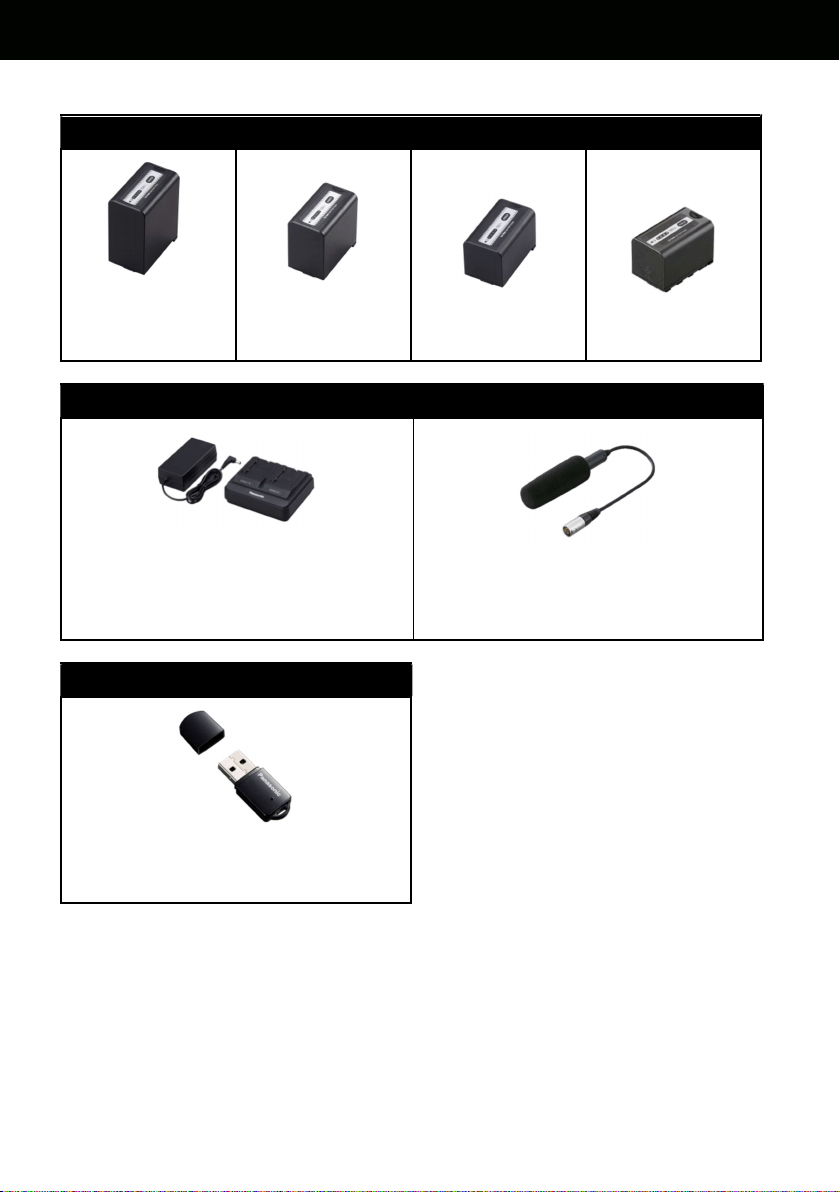
82
AU-EVA1 Genuine accessory
Battery packs (Quick charging with AG-BRD50 charger available with AG-VBR series packs)
AG-VBR118G
(11,800mAh)
AG-VBR89G
(8,850mAh)
AG-VBR59
(5,900mAh)
VW-VBD58
(5,800mAh)
Battery charger Microphone
AG-BRD50
(Supports quick charging with
AG-VBR battery packs)
AJ-MC200G
(+48V, XLR)
Wireless LAN module
AJ-WM50
(Supports 2.4GHz / 5GHz)
*Not available for some countires/regions
* Part number and design are subject to change without notice.
6. Appendix

83
6-6. Specifications
General specification
Power
DC 7.28 V (Battery Operation)
DC 12 V (AC adapter operation)
Power Consumption 19 W (when using LCD monitor)
Operating Temperature 0 °C to 40 °C (32°F to 104°F)
Operating Humidity 10% to 80% (relative humidity)
Storage Temperature -20 °C to 60 °C (-4°F to 140°F)
Weight
Body: Approx. 1.2 kg (2.65 lb) (excluding accessories)
Shooting: Approx. 2.05 kg (4.52 lb) (with accessories)
Dimensions
135 mm (W) x 133 mm (H) x 170 mm (D) (excluding protrusions and
accessories) (5-5/16 inches x 5-1/4 inches x 6-11/16 inches)
Camera unit
Image Sensor Super 35 mm, MOS sensor
Number of Pixels
Total pixels: Approx. 20.49 megapixels, 6340 (H) x 3232 (V)
Effective pixels: Approx. 17.25 megapixels, 5720 (H) x 3016 (V)
Sensor Area and Max
Frame Rate
S35: 4K/UHD 60 fps/50 fps
2K/HD 120 fps/100 fps
4/3": 2K/HD 240 fps/200 fps
Latitude 14 stop
Log V-Log
Gamma
eV-Look Gamma (2 types)
Video Gamma
Hybrid Log Gamma (HLG)
Gamut V-Gamut (V-Log)
EI Settings
[ISO] mode: NATIVE ISO: 800, 2500
800 Base: 200 to 2000
2500 Base: 1000 to 25600
[dB] mode: (Normal) -12 dB to 8 dB
(High) -8 dB to 20 dB
Shutter Speed
[deg] mode: 3.0 deg to 357.0 deg (0.5 deg step)
12 presets
[sec] mode: 1/24.1 sec to 1/8000 sec (23.98p)
12 presets
Color Temp
ATW, AWB, 2000 K to 15000 K ±10.0 GMg
12 presets
Lens Mount EF mount
Image Stabilization Electric Image Stabilization (EIS)
Auto Focus One push auto focus
ND Filter CLEAR, 0.6ND, 1.2ND, 1.8ND, Electrical driven
IR Cut Filter USER assignable IR shooting (filter ON/OFF)
6. Appendix

84
Memory card recorder
Recording Media
SDHC memory card (4 GB to 32 GB)
SDXC memory card (32 GB to 128 GB)
UHS-Ⅰ/UHS-Ⅱ UHS Speed Class3 is supported,
Video Speed Class V90 is supported
Recording Slot SD memory card slot x 2
Recording Resolution
4096 x 2160 (4K), 3840 x 2160 (UHD),
2048 x 1080 (2K), 1920 x 1080 (FHD),
1280 x 720 (HD)
Recording System
Frequency
59.94p, 50p, 29.97p, 25p, 24p, 23.98p
59.94i, 50i (AVCHD only)
2slot Functions Simul Rec, Relay Rec
Other Rec Functions Pre Rec
Digital video
Quantizing
MOV: 4:2:2 10 bit/4:2:0 8 bit
AVCHD: 4:2:0 8 bit
Video Compression
Format
H.264/MPEG-4 AVC High Profile
Digital audio
Recording Audio Format
MOV: 48 kHz/24 bit, 2 CH, Linear PCM
AVCHD: 48 kHz/16 bit, 2 CH, Dolby Audio™
Headroom 18 dB/20 dB (menu switchable)
6. Appendix

85
Video output
SDI OUT
0.8 V [p-p], 75 Ω, 4K (6G), HD (3G/1.5G)
Output format (4:2:2 10 bit):
・ 4096 x 2160: 29.97p, 25p, 24p, 23.98p
・ 3840 x 2160: 29.97p, 25p, 24p, 23.98p
・ 1920 x 1080: 59.94p, 50p, 59.94i, 50i, 29.97p, 29.97PsF, 25p, 25PsF,
24p, 24PsF, 23.98p, 23.98PsF
・ 1280 x 720p: 59.94p, 50p
RAW
*
output format (10 bit):
・ 5760 x 3072: 29.97p, 25p, 24p, 23.98p
・ 4096 x 2160: 59.94p, 50p, 29.97p, 25p, 24p, 23.98p
HDMI
HDMI x 1, TypeA, HDMI REC REMOTE is supported,
Viera Link is NOT supported
Output format (4:2:2 10 bit):
・ 4096 x 2160: 59.94p, 50p, 29.97p, 25p, 24p, 23.98p
・ 1920 x 2160: 59.94p, 50p, 29.97p, 25p, 24p, 23.98p
・ 1920 x 1080: 59.94p, 50p, 59.94i, 50i, 29.97p, 25p, 24p, 23.98p
・ 1280 x 720: 59.94p, 50p
・ 720 x 480: 59.94p
・ 720 x 576: 50p
Output format (4:2:0 8 bit):
・ 4096 x 2160: 59.94p, 50p
・ 3840 x 2160: 59.94p, 50p
Audio in/out
Internal Mic Stereo microphone
INPUT1/2
XLR (3-pin) x 2 (INPUT1/2), input high impedance, LINE/MIC/MIC +48 V
(menu switchable)
MIC: −40 dBu/−50 dBu/−60 dBu (menu switchable)
LINE: +4 dBu/0 dBu (menu switchable)
SDI OUT Linear PCM 2 CH
HDMI Linear PCM 2 CH
PHONES 3.5 mm stereo mini jack x 1
Speaker 20 mm diameter, round x 1
Other in/out
TC IN/OUT
BNC x1 for IN/OUT (menu switchable)
IN: 1.0 V [p-p] to 4.0 V [p-p], 10 kΩ
OUT: 2.0 V [p-p] ±0.5 V [p-p], low impedance
LCD 40-pin (Dedicated)
REMOTE 2.5 mm Super Mini Jack
USB 2.0 (HOST) Type-A, 4-pin for Wireless Module (AJ-WM50)
EF Mounting
Contact
8-pin
DC IN 12 V DC 12 V EIAJ type 4
6. Appendix

86
LCD monitor
Size
3.5-type LCD monitor (approx. 1,150,000 dots)
Touch panel (MENU control, Shooting assist functions)
Switches MIRROR (OFF, B/T, ROTATE)
Hand grip
Mounting
Mechanism
One touch rotatable/Detachable
Switches REC, MENU.MENU/IRIS multifunctional dial, User switch x 2
Accessories comes standard
Accessories
Battery (5900mAh), Battery charger, AC adapter, AC cable, Shoulder
strap, Microphone holder, Microphone holder adapter, LCD monitor (with
hood and mounting attachment), Handle, Grip, Grip belt, Mount cap
* Dolby, Dolby Audio, and the double-D symbol are trademarks of Dolby Laboratories.
* Specifications are subject to change without notice.
6. Appendix
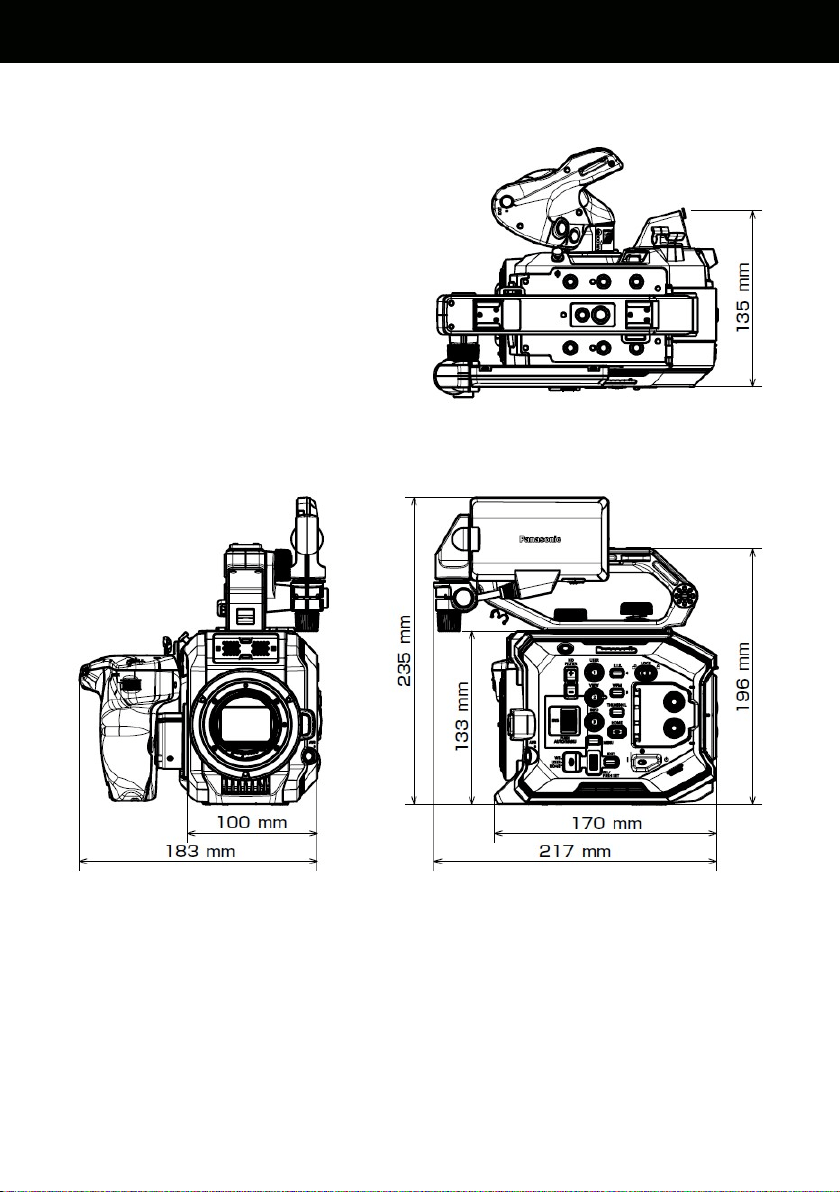
87
6-7. Dimensions
6. Appendix
6. Appendix

88
Revision history
Issued History
Document
Version
Jan 2018
First edition issued V1.00E

89
MEMO

90
MEMO

91
MEMO

92
Panasonic Corporation
Download firmware, check frequently asked questions for the AU-EVA1 at
https://panasonic.biz/cns/sav/pass_e
