Operating Instructions
Memory Card Camera-Recorder
Before using this product, be sure to read “Read this first!” (pages 2 to 7).
Before operating this product, please read the instructions carefully and save this manual for future use.
ENGLISH
DVQP2127WA
W1219MS3031 -YI
Model No. AJ-CX4000G
GJ
Read this rst!
– 2 –
Read this rst!
indicates safety information.
WARNING:
• To reduce the risk of fire, do not expose this
equipment to rain or moisture.
• To reduce the risk of fire, keep this equipment
away from all liquids. Use and store only in
locations which are not exposed to the risk of
dripping or splashing liquids, and do not place
any liquid containers on top of the equipment.
WARNING:
Always keep memory cards (optional accessory)
out of the reach of babies and small children.
CAUTION:
Do not remove panel covers by unscrewing.
No user serviceable parts inside.
Refer servicing to qualified service personnel.
CAUTION:
To reduce the risk of fire and annoying interference,
use the recommended accessories only.
CAUTION:
In order to maintain adequate ventilation, do not
install or place this unit in a bookcase, built-in
cabinet or any other confined space. To prevent
risk of fire hazard due to overheating, ensure that
curtains and any other materials do not obstruct
the ventilation.
CAUTION:
Do not lift the unit by its handle while the tripod is
attached. When the tripod is attached, its weight
will also affect the unit’s handle, possibly causing
the handle to break and hurting the user. To carry
the unit while the tripod is attached, take hold of
the tripod.
CAUTION:
Excessive sound pressure from earphones and
headphones can cause hearing loss.
CAUTION:
Do not leave the unit in direct contact with the skin
for long periods of time when in use.
Low temperature burn injuries may be suffered if
the high temperature parts of this unit are in direct
contact with the skin for long periods of time.
When using the equipment for long periods of
time, make use of the tripod.
CAUTION:
A coin type battery is installed inside of the unit.
Do not store the unit in temperatures over 60 °C
(140 °F).
Do not leave the unit in an automobile exposed to
direct sunlight for a long period of time with doors
and windows closed.
Read this rst!
– 3 –
indicates safety information.
FCC NOTICE (USA)
Supplier’s Declaration of Conformity
Trade Name: Panasonic
Model Number: AJ-CX4000G
Responsible Party: Panasonic Corporation of North America
Two Riverfront Plaza Newark NJ07102
Support contact: 1-800-524-1448
This device complies with Part 15 of the FCC Rules. Operation is subject to the following two conditions:
(1) This device may not cause harmful interference, and (2) this device must accept any interference
received, including interference that may cause undesired operation.
FCC Warning:
To assure continued FCC emission limit compliance, follow the attached installation instructions and the
user must use only shielded interface cables when connecting to host computer or peripheral devices. Also,
any unauthorized changes or modifications to this equipment could void the user’s authority to operate this
device.
FCC Caution:
This equipment has been tested and found to comply with the limits for a Class B digital device, pursuant
to Part 15 of the FCC Rules. These limits are designed to provide reasonable protection against harmful
interference in a residential installation. This equipment generates, uses and can radiate radio frequency
energy and, if not installed and used in accordance with the instructions, may cause harmful interference
to radio communications. However, there is no guarantee that interference will not occur in a particular
installation. If this equipment does cause harmful interference to radio or television reception, which can be
determined by turning the equipment off and on, the user is encouraged to try to correct the interference by
one or more of the following measures:
• Reorient or relocate the receiving antenna.
• Increase the separation between the equipment and receiver.
• Connect the equipment into an outlet on a circuit different from that to which the receiver is connected.
• Consult the dealer or an experienced radio/TV technician for help. The user may find the booklet
“Something About Interference” available from FCC local regional offices helpful.
NOTIFICATION (Canada)
CAN ICES-3(B)/NMB-3(B)
AEEE Yönetmeliğine Uygundur.
AEEE Complies with Directive of Turkey.
Manufactured by: Panasonic Corporation, Osaka, Japan
Importer’s name and address of pursuant to EU rules:
Panasonic Marketing Europe GmbH
Panasonic Testing Centre
Winsbergring 15, 22525 Hamburg, Germany

Read this rst!
– 4 –
English
Declaration of Conformity (DoC)
Hereby, “Panasonic Corporation” declares that this product
is in compliance with the essential requirements and other
relevant provisions of Directive 2014/53/EU.
Customers can download a copy of the original DoC to our
RE products from our DoC server:
http://www.doc.panasonic.de
Contact to Authorized Representative:
Panasonic Marketing Europe GmbH, Panasonic Testing
Centre, Winsbergring 15, 22525 Hamburg, Germany
Български
Декларация за съответствие (DoC)
С настоящото “Panasonic Corporation” декларира, че
този продукт е в съответствие с основните изисквания и
други съответни разпоредби на Директива 2014/53/EС.
Клиентите могат да изтеглят копие от оригиналната DoC
за нашите RE от нашия DoC сървър:
http://www.doc.panasonic.de
Свържете се с нашия упълномощен представител:
Panasonic Marketing Europe GmbH, Panasonic Testing
Centre, Winsbergring 15, 22525 Hamburg, Германия
Hrvatski
Izjava o sukladnosti (DoC)
Ovime, tvrtka “Panasonic Corporation” izjavljuje da
ovaj proizvod udovoljava osnovnim zahtjevima i ostalim
relevantnim odredbama Direktive 2014/53/EU.
Kupci mogu preuzeti kopiju originalne DoC za naše RE
proizvode s našeg DoC poslužitelja:
http://www.doc.panasonic.de
Obratite se ovlaštenom predstavniku:
Panasonic Marketing Europe GmbH, Panasonic Testing
Centre, Winsbergring 15, 22525 Hamburg, Njemačka
Suomi
Vaatimustenmukaisuusvakuutus (DoC)
Täten “Panasonic Corporation” vakuuttaa, että tämä tuote
on direktiivin 2014/53/EU keskeisten vaatimusten ja muiden
olennaisten määräysten mukainen.
Asiakkaat voivat ladata kopion alkuperäisestä DoC:sta
kaikille REtuotteillemme DoC-palvelimeltamme:
http://www.doc.panasonic.de
Valtuutetun edustajan yhteystiedot:
Panasonic Marketing Europe GmbH, Panasonic Testing
Centre, Winsbergring 15, 22525 Hamburg, Saksa
Lietuviškai
Atitikties deklaracija (DoC)
Bendrovė “Panasonic Corporation” patvirtina, kad šis
gaminys atitinka direktyvos 2014/53/ EB esminius
reikalavimus ir kitas taikytinas nuostatas.
Mūsų RE originalios DoC kopiją klientai gali atsisiųsti iš
mūsų DoC serverio:
http://www.doc.panasonic.de
Įgaliotojo atstovo adresas:
Panasonic Marketing Europe GmbH, Panasonic Testing
Centre,
Winsbergring 15, 22525 Hamburg, Vokietija
Česky
Prohlášení o shodě (DoC)
Společnost “Panasonic Corporation” tímto prohlašuje,
že tento výrobek je ve shodě se základními požadavky a
dalšími příslušnými ustanoveními směrnice 2014/53/EU.
Zákazníci si mohou stáhnout originál DoC pro naše
produkty RE z našeho serveru DoC:
http://www.doc.panasonic.de
Kontakt na Autorizovaného obchodního zástupce:
Panasonic Marketing Europe GmbH, Panasonic Testing
Centre,
Winsbergring 15, 22525 Hamburg, Německo
Dansk
Overensstemmelseserklæring (DoC)
Hermed erklærer “Panasonic Corporation”, at dette
produkt opfylder de væsentligste krav og andre relevante
bestemmelser fastsat i direktiv 2014/53/EU.
Kunder kan downloade en kopi af det originale DoC for
vores REprodukter fra vores Doc-server:
http://www.doc.panasonic.de
Kontakt til autoriseret repræsentant:
Panasonic Marketing Europe GmbH, Panasonic Testing
Centre, Winsbergring 15, 22525 Hamburg, Tyskland
Nederlands
Verklaring van Conformiteit (DoC)
Bij dezen verklaart “Panasonic Corporation” dat dit product
in overeenstemming is met de essentiële vereisten en
andere relevante uiteenzettingen van Richtlijn 2014/53/EU.
Klanten kunnen een kopie downloaden van het originele
DoC bij onze RE producten vanaf onze DoC server:
http://www.doc.panasonic.de
Neem contact op met de bevoegde vertegenwoordiger:
Panasonic Marketing Europe GmbH, Panasonic Testing
Centre, Winsbergring 15, 22525 Hamburg, Duitsland
Norsk
Samsvarserklæring (DoC)
“Panasonic Corporation” erklærer herved at dette produktet
samsvarer med de grunnleggende kravene og andre
relevante bestemmelser i direktivet 2014/53/EU.
Kundene kan laste ned en kopi av original DoC for våre
REprodukter fra vår DoC-server:
http://www.doc.panasonic.de
Kontaktinformasjon autorisert representant:
Panasonic Marketing Europe GmbH, Panasonic Testing
Centre, Winsbergring 15, 22525 Hamburg, Tyskland
Eesti
Vastavusdeklaratsioon (DoC)
Käesolevaga kinnitab “Panasonic Corporation”, et see
toode vastab direktiivi 2014/53/EL olulistele nõuetele ja
teistele asjakohastele sätetele.
Kliendid saavad originaalse DoC meie RE-toodetele alla
laadida meie DoC serverist:
http://www.doc.panasonic.de
Võtke ühendust volitatud esindajaga:
Panasonic Marketing Europe GmbH, Panasonic Testing
Centre, Winsbergring 15, 22525 Hamburg, Saksamaa

Read this rst!
– 5 –
Magyar
Megfelelőségi nyilatkozat (DoC)
A “Panasonic Corporation” ezennel kijelenti, hogy ez
a termék megfelel a 2014/53/EU irányelv lényeges
követelményeinek és egyéb vonatkozó rendelkezéseinek.
A vásárlók az alábbi címen elérhető DoC szerverünkről
töltheti le az RE termékeinkhez tartozó eredeti DoC
másolatát:
http://www.doc.panasonic.de
A hivatalos képviselő elérhetősége:
Panasonic Marketing Europe GmbH, Panasonic Testing
Centre, Winsbergring 15, 22525 Hamburg, Németország
Ελληνικάa
Δήλωση Συμμόρφωσης (DoC)
Η “Panasonic Corporation” δηλώνει ότι το προϊόν αυτό
είναι συμμορφωμένο προς τις βασικές απαιτήσεις και άλλες
σχετικές διατάξεις της Οδηγίας 2014/53/EΕ.
Ο πελάτες μπορούν να κατεβάσουν ένα αντίγραφο
του πρωτοτύπου DoC σχετικό με τα προϊόντα μας RE
(ραδιοεξοπλισμός) από το δικό μας σέρβερ DoC:
http://www.doc.panasonic.de
Επικοινωνήστε με τον Εξουσιοδοτημένο Αντιπροσωπό μας:
Panasonic Marketing Europe GmbH, Panasonic Testing
Centre, Winsbergring 15, 22525 Hamburg, Γερμανία
Polski
Deklaracja zgodności (DoC)
“Panasonic Corporation” niniejszym oświadcza, że ten
produkt jest zgodny zzasadniczymi wymogami oraz innymi
właściwymi postanowieniami Dyrektywy 2014/53/UE.
Kopię oryginalnej DoC obejmującej nasz RE klienci mogą
pobrać z naszego serwera DoC:
http://www.doc.panasonic.de
Kontakt z autoryzowanym przedstawicielem:
Panasonic Marketing Europe GmbH, Panasonic Testing
Centre, Winsbergring 15, 22525 Hamburg, Niemcy
Português
Declaração de Conformidade (DoC)
Com o presente documento, a “Panasonic Corporation”
declara que este produto se encontra em conformidade
com os requisitos especícos e demais especicações
referentes à Diretiva 2014/53/UE.
Os clientes podem descarregar uma cópia da DoC original
para os nossos produtos RE a partir do nosso servidor
DoC:
http://www.doc.panasonic.de
Contacto com um Representante Autorizado:
Panasonic Marketing Europe GmbH, Panasonic Testing
Centre, Winsbergring 15, 22525 Hamburg, Alemanha
Latviski
Atbilstības deklarācija (DoC)
Ar šo “Panasonic Corporation” paziņo, ka šis izstrādājums
atbilst pamatprasībām un pārējiem Direktīvas 2014/53/ES
noteikumiem.
Oriģinālās DoC kopiju klienti var lejupielādēt pie mūsu RE
produktiem no mūsu DoC servera:
http://www.doc.panasonic.de
Lūdzam sazināties ar pilnvaroto parstāvi:
Panasonic Marketing Europe GmbH, Panasonic Testing
Centre, Winsbergring 15, 22525 Hamburg, Vācijā
Română
Declaraţie de Conformitate (DoC)
“Panasonic Corporation” declară prin prezenta că acest
produs este conform cu cerinţele esenţiale şi alte prevederi
relevante ale Directivei 2014/53/UE.
Clienţii pot descărca o copie a DoC pentru produsele
noastre RE de pe serverul nostru DoC:
http://www.doc.panasonic.de
Contactaţi Reprezentantul Autorizat:
Panasonic Marketing Europe GmbH, Panasonic Testing
Centre, Winsbergring 15, 22525 Hamburg, Germania
Svenska
Försäkran om Överensstämmelse (DoC)
Härmed garanterar “Panasonic Corporation” att denna
produkt överensstämmer med tillämpbara krav och andra
föreskrifter i enlighet med direktiv 2014/53/EU.
Kunder kan hämta en kopia av den ursprungliga DoC för
våra RE-produkter från vår DoC-server:
http://www.doc.panasonic.de
Kontakt till Auktoriserad Representant:
Panasonic Marketing Europe GmbH, Panasonic Testing
Centre, Winsbergring 15, 22525 Hamburg, Tyskland
Slovensky
Vyhlásenie o zhode (DoC)
“Panasonic Corporation” týmto vyhlasuje, že tento výrobok
je v súlade so základnými požiadavkami a ďalšími
príslušnými ustanoveniami smernice 2014/53/EU.
Zákazníci si môžu prevziať kópiu pôvodného dokumentu
DoC pre naše výrobky RE z nášho servera DoC:
http://www.doc.panasonic.de
Kontakt na splnomocneného zástupcu:
Panasonic Marketing Europe GmbH, Panasonic Testing
Centre, Winsbergring 15, 22525 Hamburg, Nemecko
Slovenščina
Izjava o skladnosti (DoC)
“Panasonic Corporation” s tem dokumentom izjavlja,
da je izdelek v skladu z bistvenimi zahtevami in drugimi
pomembnimi določbami Direktive 2014/53/EU.
Stranke lahko prenesejo kopijo izvirnega dokumenta DoC
za izdelke RE z našega strežnika DoC:
http://www.doc.panasonic.de
Naslov pooblaščenega predstavnika:
Panasonic Marketing Europe GmbH, Panasonic Testing
Centre, Winsbergring 15, 22525 Hamburg, Nemčija
Türkçe
Uygunluk Beyanı (DoC)
“Panasonic Corporation” işbu belge ile bu ürünün 2014/53/
EU sayılı Direktif’in temel gereklerine ve diğer ilgili
hükümlerine uygun olduğunu beyan etmektedir.
Müşterilerimiz RE ürünlerimizle ilgili orijinal DoC belgesinin
bir kopyasını DoC sunucumuzdan indirebilir:
http://www.doc.panasonic.de
Yetkili Temsilci ile temasa geçin:
Panasonic Marketing Europe GmbH, Panasonic Testing
Centre, Winsbergring 15, 22525 Hamburg, Almanya
Read this rst!
– 6 –
Disposal of Old Equipment and Batteries
Only for European Union and countries with recycling systems
These symbols on the products, packaging, and/or accompanying documents mean that used electrical and electronic
products and batteries must not be mixed with general household waste.
For proper treatment, recovery and recycling of old products and used batteries, please take them to applicable collection
points in accordance with your national legislation.
By disposing of them correctly, you will help to save valuable resources and prevent any potential negative effects on human
health and the environment.
For more information about collection and recycling, please contact your local authority, dealer or supplier.
Penalties may be applicable for incorrect disposal of this waste, in accordance with national legislation.
Note for the battery symbol (bottom symbol):
This symbol might be used in combination with a chemical symbol. In this case it complies with the requirement set by the
Directive for the chemical involved.
TO REMOVE BATTERY
Main Power Battery (Ni-Cd / Ni-MH / Li-ion Battery)
• To detach the battery, please proceed in the reverse order of the installation method described in this manual.
• If a battery made by any other manufacturer is to be used, check the Operating Instructions accompanying the battery.
Back-up Battery (Lithium Battery)
• For the removal of the battery for disposal at the end of its service life, please consult your dealer.
Battery recycling symbol (valid only in Taiwan)
EU
Read this rst!
– 7 –
ІНФОРМАЦІЯ ПРО ПІДТВЕРДЖЕННЯ ВІДПОВІДНОСТІ ПРОДУКТУ
Виробник: Panasonic Corporation Панасонік Корпорейшн
Адреса виробника: Kadoma, Osaka, Japan Кадома, Осака, Японія
Країна походження: Japan/China Японія/Китай
Уповноважений Представник: ТОВ “ПАНАСОНІК УКРАЇНА ЛТД”
Адреса Уповноваженого Представника: вул. Васильківська, буд. 30, м. Київ, 03022, Україна
Примітки:
Термін служби виробу 7 років
Дату виготовлення можна визначити за комбінацією букв і цифр серійного номера, що розташований на маркувальній
табличці виробу.
Приклад: X X
XXXXXXX
Рік: остання цифра року (5 – 2015, 6 – 2016,…0 – 2020)
Місяць: А – Січень, В – Лютий… L – Грудень
Декларація про відповідність
Справжнім компанія Panasonic Corporation заявляє, що професійні відеокамери AJ-CX4000 відповідають Технічному
регламенту радіообладнання.
Повний текст декларації про відповідність доступний на веб- сайті
https://service.panasonic.ua (розділ «Технічне регулювання»)
Частота: 1575,42 МГц (GPS)
Максимальна потужність передачі: N / A
< Предупреждение >
Следуйте нижеприведённым правилам, если иное не указано в других документах.
1. Устанавливайте прибор на твёрдой плоской поверхности, за исключением отсоединяемых или несъёмных
частей.
2. Хранить в сухом, закрытом помещении.
3. Во время транспортировки не бросать, не подвергать излишней вибрации или ударам о другие предметы.
4. Утилизировать в соответствии с национальным и/или местным законодательством.
Правила и условия реализации не установлены изготовителем и должны соответствовать национальному и/или
местному законодательству страны реализации товара.
r The symbols on this product (including the accessories) represent the following.
e
DC
ON
Standby (OFF)

– 8 –
Trademark
f SDXC logo is a trademark of SD-3C, LLC.
f The terms HDMI and HDMI High-Denition Multimedia Interface, and the HDMI Logo are trademarks or registered trademarks of HDMI Licensing
Administrator, Inc. in the United States and other countries.
f Microsoft
®
and Windows
®
are registered trademarks or trademarks of Microsoft Corporation in the United States and/or other countries.
f Screenshots are used according to Microsoft Corporation guidelines.
f Intel
®
, Pentium
®
, Celeron
®
, and Intel
®
Core
TM
are trademarks of Intel Corporation in the United States and/or other countries.
f Mac and Mac OS are trademarks of Apple Inc. registered in the United States and/or other countries.
f iPhone/iPad are trademarks of Apple Inc. registered in the United States and/or other countries.
f App Store is a service mark of Apple Inc.
f Android and Google Play are trademarks or registered trademarks of Google LLC.
f Wi-Fi
®
is a registered trademark of Wi-Fi Alliance
®
.
f WPA
TM
and WPA2
TM
are trademark of Wi-Fi Alliance
®
.
f NDI
®
is a registered trademark of NewTek, Inc.
f MMC (Multi Media Card) is a registered trademark of Inneon Technologies AG.
f Java and all Java-based trademarks are trademarks or registered trademarks of Sun Microsystems, Inc. in the United States.
f UniSlot is a registered trademark of Ikegami Tsushinki CO., LTD.
f The use of DCF Technologies is under license from Multi-Format, Inc.
f All other names, company names, product names, etc., contained in this instruction manual are trademarks or registered trademarks of their
respective owners.
License
f This product is licensed under the AVC Patent Portfolio License. All other acts are not licensed except private use for personal and non-prot purposes
such as what are described below.
-To record video in compliance with the AVC standard (AVC Video)
-To play back AVC Video that was recorded by a consumer engaged in a personal and non-commercial activity
-To play back AVC Video that was obtained from a video provider licensed to provide the video
Visit the MPEG LA, LLC website (http://www.mpegla.com/) for details.
f Separate license contract with MPEG-LA is required to record in a memory card with this product and to distribute that card to end users for a prot.
The end user mentioned here indicates a person or organization that handles contents for a personal use.
Software information about this product
1 This product includes software licensed under GNU General Public License (GPL) and GNU Lesser General Public License (LGPL), and
customers are hereby notied that they have rights to obtain, re-engineer, and redistribute the source code of these software.
2 This product includes software licensed under MIT-License.
3 This product includes software developed by the OpenSSL Project for use in the OpenSSL Toolkit (http://www.openssl.org/).
4 This product includes software licensed under OpenBSD License.
5 This product includes PHP, freely available from <http://www.php.net/>.
6 This software is based in part on the work of the Independent JPEG Group.
7 This product includes software licensed under the MOZILLA PUBLIC LICENSE.
For details on each license, refer to the terms of license.
The terms of license can be displayed using the following method.
f Select the [OTHERS] menu → [USB DEVICE] → [SERVICE MODE] → [YES].
Select “LICENSE.TXT” in the external drive recognized by the computer.
For details on these descriptions (originally provided in English) and how to obtain the source code, visit the following website.
https://pro-av.panasonic.net/
We do not accept inquiries about the details of the source code obtained by the customer.
Excluding the open source software licensed based on GPL/LGPL, etc., transferring, copying, reverse assembling, reverse compiling, and reverse
engineering of the software included in the camera is prohibited. Also, exporting of any software included in the camera against the export laws and
regulations is prohibited.

– 9 –
How to read this document
r Illustrations
f Illustrations of the product appearance, menu screens, etc., may vary from the actual.
r Conventions used in this manual
f Words and phrases in [ ] brackets indicate content displayed in the LCD monitor, etc.
f Words and phrases in < > brackets indicate design text used on this camera, such as button names.
r Reference pages
f Reference pages in this document are indicated by (page 00).
r Terminology
f SD memory card, SDHC memory card, and SDXC memory card are referred to only as “SD card” unless distinguished otherwise.
f A memory card with the “expressP2” logo is referred to as a “expressP2 card”.
f A memory card with the “microP2” logo is referred to as a “microP2 card”.
f expressP2 card and microP2 card are referred to only as a “P2 card” unless distinguished otherwise.
f P2 card and SD card are referred to only as a “memory card” unless distinguished otherwise.
f Video that is created during a single recording operation is referred to as a “clip”.

Contents
– 10 –
Contents
Read this rst! 2
Chapter 1 Overview 12
Before using the camera
13
Accessories 15
When turning on the power for the rst time 16
[AREA SETTINGS] 16
[TIME ZONE] 17
[CLOCK SETTING] 17
Use of the camera on a system 18
Basic conguration devices 18
Expanded conguration devices 18
Accessories 18
Chapter 2 Description of Parts 19
Power supply and accessory mounting section
20
Audio (input) function section 22
Audio (output) function section 24
Shooting and recording/playback functions section 25
Shooting and recording (Camera unit) 25
Shooting and recording/playback functions section (Recording
unit) 27
Menu operation section and thumbnail operation section 29
Time code section 30
Warning and status display section 31
Display inside the display window 32
Display of remaining memory card capacity, remaining battery
level, and recording level 32
Chapter 3 Preparation 33
Power supply
34
To use a battery 34
Attaching and setting the battery 34
Using external DC power supply 35
Mounting and adjusting the lens 37
Mounting the lens 37
Adjusting lens ange back 38
White shading compensation function 38
Chromatic aberration compensation function (CAC) 39
Preparing for audio input 43
Using the front microphone 43
Using the wireless microphone receiver 43
Using audio devices 43
Mounting accessories 44
Mounting the camera on a tripod 44
Attaching the shoulder strap 44
Attaching the rain cover 45
Charging the built-in battery 46
Setting the date/time of the internal clock 47
Inspections before shooting 48
Preparing to inspect 48
Inspecting the camera unit 48
Inspecting the memory recording functions 48
Preparing the memory card 51
Memory cards supported on the camera 51
Memory cards 52
Inserting the memory card 52
Removing the memory card 5 2
Preventing accidental erasure 53
Status of the card access lamp and the memory card 53
Memory card recording time 54
Handling recording data 55
Chapter 4 Operation 58
Basic operation of the menu
59
Conguration of the menu 59
Basic operation of the menu 59
Menu display 61
Displaying the menu 61
Initializing the menu
61
Menu settings 62
[THUMBNAIL] menu 62
[CAMERA] menu 63
[SCENE FILE] menu 68
[AUDIO] menu 81
[VIDEO OUT/LCD/VF] menu 85
[RECORDING] menu 98
[NETWORK] menu 101
[SYSTEM] menu 107
[OTHERS] menu 108
[OPTION] menu 112
Factory setting value of the scene le 113
[SCENE FILE] menu 113
Target items for scene le/setup le/initialization 116
[THUMBNAIL] menu 11 6
[CAMERA] menu 116
[SCENE FILE] menu 117
[AUDIO] menu 119
[VIDEO OUT/LCD/VF] menu 120
[RECORDING] menu 122
[NETWORK] menu 122
[SYSTEM] menu 124
[OTHERS] menu 124
[OPTION] menu 125
Chapter 5 Shooting 126
Basic procedures
127
Preparing power supply and inserting memory cards 127
Switch settings for shooting 127
Adjustments for shooting 128
Normal recording 128
Adjusting the white and black balance 129
White balance adjustment 129
Black balance adjustment 131
Setting the electronic shutter 132
Shutter mode 132
Setting the shutter mode/shutter speed 132
Setting synchro scan mode 132
Flash band compensation (FBC) function 133
Setting the ash band compensation function 133
Setting high dynamic range (HDR) 135
Recording in high dynamic range (HDR) 135
Playing back the signal recorded in high dynamic range (HDR) 135
Assigning function to the USER buttons 136
Selectable functions 136
[USER SW GAIN] switching setting 137
Selecting audio input signal and adjusting recording level 138
Selecting audio input signals 138
Adjusting recording level 138
Special recording function 140
Pre-recording 140
Relay recording 140
Simultaneous recording 141
Interval recording 141
Recording the proxy data 142
Hot swap recording 143
Recording check function 143
Clip metadata recording function 143
Shot mark recording function 146
Selecting the resolution, codec, and frame rate for recording
video 147
Selecting external reference signal and genlock setting 149
Locking the video signal to the external reference signal 149
Setting of time data 150
Denition of time data 150
Setting user bits 150
How to input user bits 150
Setting time code 151
Externally locking the time code 152
Display of the viewnder status 153
Lamp display in the viewnder 153
Conguration of status display on viewnder screen 153
Selecting display items on viewnder screen 153
Screen display during shooting 154
Screen display during playback 159
Checking and displaying shooting status 159
Mode check display 161
Convenient shooting functions
165
Setting the marker display 165
Marker conrmation screen (marker select function) 165
Displaying zebra pattern 165
Focus assist function 166
Waveform monitor function 167

Contents
– 11 –
Adjusting and setting the LCD monitor 168
Using the LCD monitor 168
Mirror shooting 168
Adjusting and setting the viewnder 169
Using the viewnder 169
Handling setting data 170
File structure of the setting data 170
Operating SD cards 171
Setup le 171
Scene le 173
Scene les 173
Returning the setting value of the menu to the factory setting 174
Lens les 175
Writing and loading lens les to and from SD card 176
Chapter 6 Playback 178
Thumbnail operation
179
Thumbnail operation overview 179
Thumbnail screen 179
Copying clips 183
Deleting clips 184
Protecting clips 185
Adding shot mark to a clip 185
Restoring clips 185
Linking the incomplete clips 186
Playing back clips 187
Useful playback function 189
Resume play 189
Still image recording function 190
Chapter 7 Output 191
Output format
192
Format that can be output from the <SDI OUT1> terminal 192
Format that can be output from the <SDI OUT2> terminal 192
Format that can be output from the <HDMI> terminal 193
Chapter 8 Connecting to External Devices 195
Connection function via the <USB DEVICE> terminal
196
Connecting to a computer in the card reader mode 196
Connecting with a recording device or a monitor 197
Connecting external devices and recording control
function 198
Remote function 198
Conrming the control output status 198
Remote control by iPhone/iPad or Android terminal 199
Connecting the Remote Operation Panel (AK-HRP1000G/
AK-HRP1005G) 200
Chapter 9 Network Connection 201
Network connection
202
Available functions 202
Preparing for connection 203
For the wireless module AJ-WM50 203
For the wired LAN 203
For USB tethering 204
Network settings 205
Wireless LAN settings 205
Wired LAN settings 206
USB tethering setting 207
Specifying the network settings using the settings tool 208
Conrming the network status 209
Checking the network environment 209
Saving the check results 210
Connecting to the iPhone/iPad or Android terminal 211
Mounting the wireless module 211
Camera settings 211
Preparing the CX ROP app 212
Connecting to the CX ROP application 212
Operation while the CX ROP app is connected 212
Connecting with the Remote Operation Panel
(AK-HRP1000G/AK-HRP1005G) 213
Camera settings 213
Setting the Remote Operation Panel (AK-HRP1000G/
AK-HRP1005G)
213
Operation during remote control 213
Streaming function 215
Basic setting of the camera 215
Setting for each protocol and starting the streaming 217
Management of setting information 219
Entering the setting using the setting tool 220
NDI|HX function 222
Camera settings 222
Using the cloud service 224
Remote operation of the streaming 224
Contents upload 224
Other operations 225
Chapter 10 Maintenance 226
Warning system
227
Warning list 227
Alert 229
Message 230
Recording function that cannot be used simultaneously 232
Updating the camera rmware 233
Chapter 11 Specication 234
Dimensions
235
Specications 236
General 236
Camera unit 236
Memory card recorder 236
Digital video 237
Digital audio 237
Streaming 238
Video output 238
Audio input/output 238
Other input/output 239
Monitor
239
Details of the connector signals 240
Index 243

Before using the camera, read this chapter.
Chapter 1 Overview

– 13 –
Chapter 1 Overview — Before using the camera
Before using the camera
r Before using the camera, always check if the built-in battery is not consumed, and then set the date/time.
The internal clock of the camera is reset when the built-in battery has been consumed. This may result in the meta data of the clip not being recorded
correctly, and it may not be displayed correctly in the thumbnail screen.
Check if the built-in battery is not consumed before using. (page 46)
Also, set the correct date/time.
For details about setting the time zone and date/time, refer to [TIME ZONE] (page 17) and [CLOCK SETTING] (page 17).
r Do not use the unit in oily-smoky or dusty places.
Performance may be adversely affected if small particles or other foreign objects get inside the product.
Take extra care in environments where a special effect such as theatrical smoke is used.
r Memory cards
f The surface of camera or the memory card may get slightly hot when used for a long period of time, but this is not a malfunction.
f The amount of memory included on the label of the memory card is the total amount of memory below.
-Capacity to protect and manage copyright
-Capacity usable as the normal memory on the camera or a PC.
f Do not give a strong impact to, bend, or drop the memory card.
f Memory card data may become destroyed or erased in the following cases.
-Electrical noise or static electricity
-Malfunction of the camera or the memory card
f Do not perform following operations while accessing a memory card.
-Removing the memory card
-Disconnecting battery or the external DC power supply without turning off the camera
-Apply vibration of impact
r Caution regarding laser beams
The MOS sensor may be damaged if the MOS sensor is subjected to light from a laser beam.
Take sufcient care to prevent laser beams from striking the lens when shooting in an environment where laser devices are used.
r Note the following points.
f If you prepare to record important images, always shoot some advance test footage to verify that both pictures and sound are being recorded
normally.
f Panasonic will not assume liability when video or audio recording fails due to a malfunction of the camera or the memory card during the use.
f Set the calendar (datetime of the internal clock) and the time zone, or check the setting before recording. This will have an effect on the management
of the recorded contents.
r Cautions when throwing memory cards away or transferring them to others
Formatting memory cards or deleting data using the functions of the camera or a computer will merely change the le management information: it will
not completely erase the data on the cards.
It is recommended to completely erase the data in following method when discarding/conveying.
f Physically destroy the memory card itself
f Completely erase the data in the memory card using a commercially available data erasing software for PC, etc.
Users are responsible for managing the data stored in their memory card.
r LCD monitor
f Do not continuously display the same image or text on the LCD monitor for a long period of time. The image may be burned on to the screen. It will
return to normal after leaving the camera recorder turned off for several hours.
f Condensation sometimes forms on the LCD panel of the LCD monitor in locations subject to extreme temperature differences. If this happens, wipe
with a soft, dry cloth.
f The LCD monitor will be slightly darker than normal immediately after the power is turned on when the camera is very cold. It will return to its regular
brightness when the internal temperature increases.
f The LCD monitor is managed with high precision so that at least 99.99% of the dots are effective, but there may be 0.01% or less of missing pixels or
pixels always lit. This is not a malfunction and it has no effect whatsoever on the recorded images.
f It may become difcult to see or difcult to recognize the touch when a LCD protection sheet is afxed.
r GPS
GPS (Global Position System) satellites are controlled by the US Department of State, and their accuracy may be intentionally changed.
Perform positioning at a location well open to the sky and avoid locations subject to obstacles such as indoors or around trees.
Depending on the surrounding environment or the time of the day, it may take a long time to perform positioning or there may be a signicant error in the
positioning.
r Exemption of liability
Panasonic is not liable in any way regarding following.
1 Incidental, special, or consequential damages caused directly or indirectly by the camera
2 Damages, breakage of the camera, etc., caused by misuse or carelessness of the customer
3 When disassembly, repair, or modication (including the software) of the camera is performed by the customer
4 Inconveniences, damnication, or damages by not being able to record and/or display the video due to any reasons including failure or
malfunction of the camera

– 14 –
Chapter 1 Overview — Before using the camera
5 Inconveniences, damnication, or damages resulting from malfunction of the system combining with any third party equipment
6 A liability claim or any claim for a privacy violation by an individual or a group that was the subject of the video that the customer has
shot (including recording) that became public by any reason (including using with the network user authentication turned OFF)
7 The registered information is lost due to any reason (including initializing this camera because the authentication information such as
user name or password is forgotten)
r Cautions regarding network
Since this camera is used connected to a network, following mischief may occur.
1 Leaking or divulging of information through the camera
2 Fraudulent operation of the camera by a malicious third party
3 Obstruction and/or stopping of the camera by a malicious third party
It is customer’s responsibility to take sufcient network security measures including the following to prevent damage caused by such mischief. Please
note that Panasonic is not liable in any way for damage caused by such mischief.
f Use the camera on a network where safety is secured by using a rewall, etc.
f When using the camera on a system where a computer, tablet, smartphone, or other device is connected, make sure that checking and cleaning of
infection by computer virus and malicious program is performed periodically.
f In order to prevent malicious attacks, use text strings that have 8 characters or more including 3 or more character types for the authentication
information (such as user name and password) so that a third party cannot guess your authentication information.
f Set and store the authentication information (user name, password, etc.) appropriately so it is not visible to the third party.
f Periodically change the authentication information (user name, password, etc.) and do not use the same authentication information as other accounts.
f To prevent the setting information in the camera to leak to the network, execute measure such as restricting the access with user authentication, etc.
f Do not install in a location where the camera, cable, etc., can be easily damaged.
r Security
Take caution in handling the camera or memory card so it is not stolen, lost or neglected, and handle with care when discarding or providing. Note that
Panasonic is not liable to leakage, falsication, or loss of information caused by them.

– 16 –
Chapter 1 Overview — When turning on the power for the rst time
When turning on the power for the rst time
The camera is shipped with the region of use not set.
[AREA SETTINGS] is displayed in the LCD monitor when the power is turned on for the rst time.
Follow the guidance and make the settings in the order of [AREA SETTINGS], [TIME ZONE], and then [CLOCK SETTING].
f There are two methods of operation, a method to operate with the jog dial button or the cursor operation button, and a method to touch the LCD
monitor.
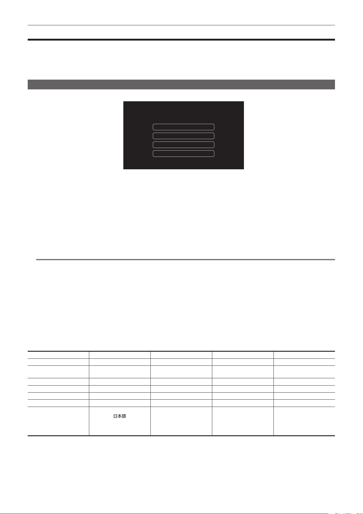
[AREA SETTINGS]
Set the region of use.
AREA1: Japan/Taiwan/Korea
AREA2: USA/Canada/Latin America
AREA3: Europe
AREA4: Other Asia/Oceania/India
AREA SETTINGS
Please select the region of use.
1
Connect the charged battery or the external DC power supply to the camera, and set the power switch to < j > (ON).
The [AREA SETTINGS] screen is displayed.
2
Select the region of use.
[AREA 1]: Japan, Taiwan, South Korea
[AREA 2]: United States of America, Canada, Central and South America regions
[AREA 3]: Europe
[AREA 4]: Asia region (excluding Japan, Taiwan, South Korea), Oceania region, India
3
When the confirmation message is displayed, select [YES].
The camera will be initialized in accordance to the region selected in Step 2. The camera will automatically restart.
Once the setting for [AREA SETTINGS] is completed, the [TIME ZONE] screen is displayed.
@
NOTE
t Once this is set, the [AREA SETTINGS] screen is not displayed from the next startup.
t To change the region of use, set with the [OPTION] menu → [AREA SETTINGS].
r Setting contents of each region of use
[RECORDING] → [REC MEDIA] is set to [microP2/SD].
Following setting differs depending on the selected region.
f The [SYSTEM] menu → [FREQUENCY]
f The [SYSTEM] menu → [REC FORMAT]
f The [OTHERS] menu → [CLOCK] → [DATE FORMAT]
f The [AUDIO] menu → [REC CH SETTINGS] → [HEAD ROOM]
f The [AUDIO] menu → [INPUT SETTINGS] → [REAR LINE IN LEVEL]
f The [AUDIO] menu → [OUTPUT SETTINGS] → [AUDIO OUT LEVEL]
f The [OTHERS] menu → [LANGUAGE]
Item [AREA 1] [AREA 2] [AREA 3] [AREA 4]
[FREQUENCY] [59.94Hz] [59.94Hz] [50.00Hz] [50.00Hz]
[REC FORMAT] [2160-59.94p/HEVC
LongGOP 100M]
[2160-59.94p/HEVC
LongGOP 100M]
[2160-50.00p/HEVC
LongGOP 100M]
[2160-50.00p/HEVC
LongGOP 100M]
[DATE FORMAT] [Y-M-D] [M-D-Y] [D-M-Y] [D-M-Y]
[HEAD ROOM] [20dB] [20dB] [18dB] [18dB]
[REAR LINE IN LEVEL] [4dB] [4dB] [0dB] [4dB]
[AUDIO OUT LEVEL] [4dB] [4dB] [0dB] [4dB]
[LANGUAGE] [English]
[
]
[English]
[Français]
[Español]
[English]
[Français]
[Deutsch]
[Español]
[Italiano]
[English]
[Français]
[Español]
– 17 –
Chapter 1 Overview — When turning on the power for the rst time
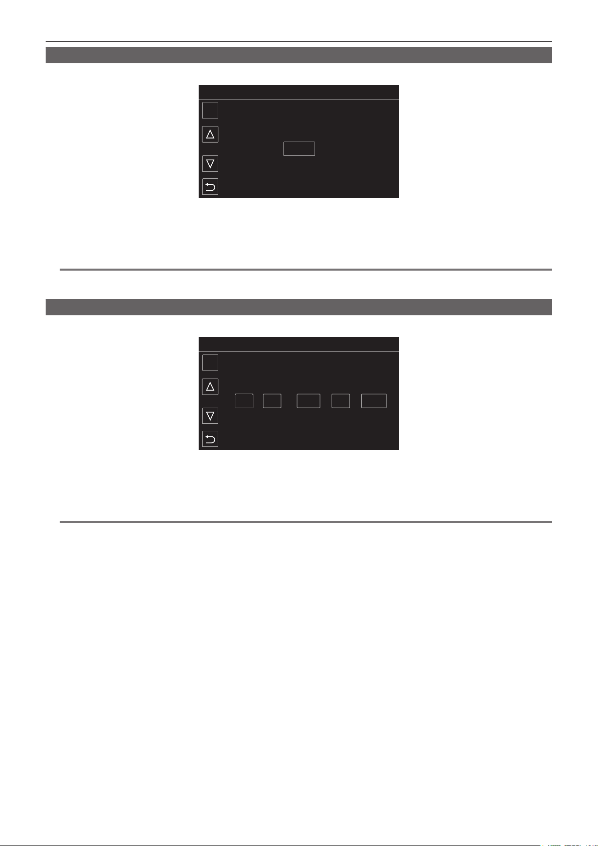
[TIME ZONE]
Set the time difference from the Greenwich Mean Time.
TIME ZONE
SET
+0:00
1
Set the time difference.
2
Select [SET].
Once the setting for [TIME ZONE] is completed, the [CLOCK SETTING] screen is displayed.
@
NOTE
t The setting for the date/time of the camera changes together with the time zone settings.
t This can also be set with the [OTHERS] menu → [CLOCK] → [TIME ZONE].
[CLOCK SETTING]
Set the year, month, date, and time.
CLOCK SETTING
SET
0
0: . .1 2019
JAN
1
Set the year, month, date, and time.
2
Select [SET].
Once the setting is complete, the camera image screen is displayed on the LCD monitor.
@
NOTE
t This can also be set with the [OTHERS] menu → [CLOCK] → [CLOCK SETTING].
– 18 –
Chapter 1 Overview — Use of the camera on a system
Use of the camera on a system
Parts other than the camera are optionally available. Use the following recommended parts.
Basic conguration devices
Equipment necessary for shooting with the camera, such as lenses, batteries, etc.
Part name Part No. Remark
Electronic HD color view nder AG-CVF15G/AJ-CVF25G/AJ-CVF50G “Adjusting and setting the viewnder” (page 169)
Super-directional electret stereo microphone
(phantom +48V)
AJ-MC900G “Using the front microphone” (page 43)
Lens (Bayonet type) FUJINON/CANON “Mounting and adjusting the lens” (page 37)
Battery
Anton/Bauer battery*
1
Dionic/Hytron/Titon/Digital series
“Attaching and setting the battery” (page 34)
SD card*
2
expressP2 card*
2
microP2 card*
2
Visit the support desk at the website*
2
“Memory cards” (page 52)
*1 A battery holder is provided as standard on the main unit.
*2 For the latest information not included in these Operating Instructions, refer to the support desk at the following website.
https://pro-av.panasonic.net/
Expanded conguration devices
The following devices are also available in addition to the basic conguration devices.
Part name Part No. Remark
Remote Operation Panel AK-HRP1000G/AK-HRP1005G
“Connecting the Remote Operation Panel
(AK-HRP1000G/AK-HRP1005G)” (page 200)
Wireless module AJ-WM50 “For the wireless module AJ-WM50” (page 203)
Memory card drive AU-XPD3 —
UniSlot wireless microphone receiver — —
External DC power supply — “Using external DC power supply” (page 35)
For details on wireless modules that can be connected, refer to the support desk at the following website.
https://pro-av.panasonic.net/
Accessories
Part name Part No. Remark
Rain cover SHAN-RC700 “Attaching the rain cover” (page 45)
Tripod adaptor SHAN-TM700 “Mounting the camera on a tripod” (page 44)

This chapter describes the names, functions, and operations of parts on the camera.
Chapter 2 Description of Parts
– 20 –
Chapter 2 Description of Parts — Power supply and accessory mounting section
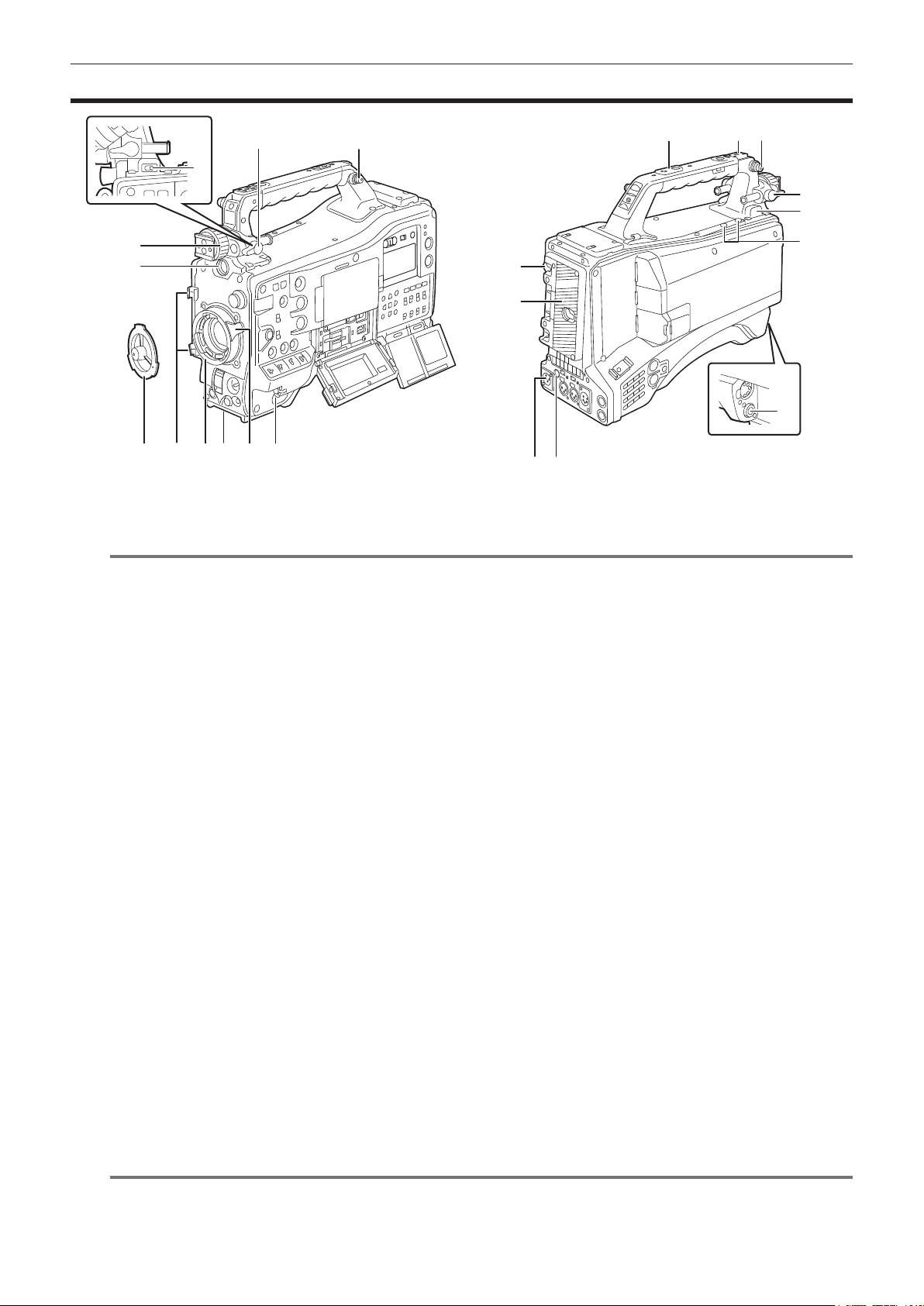
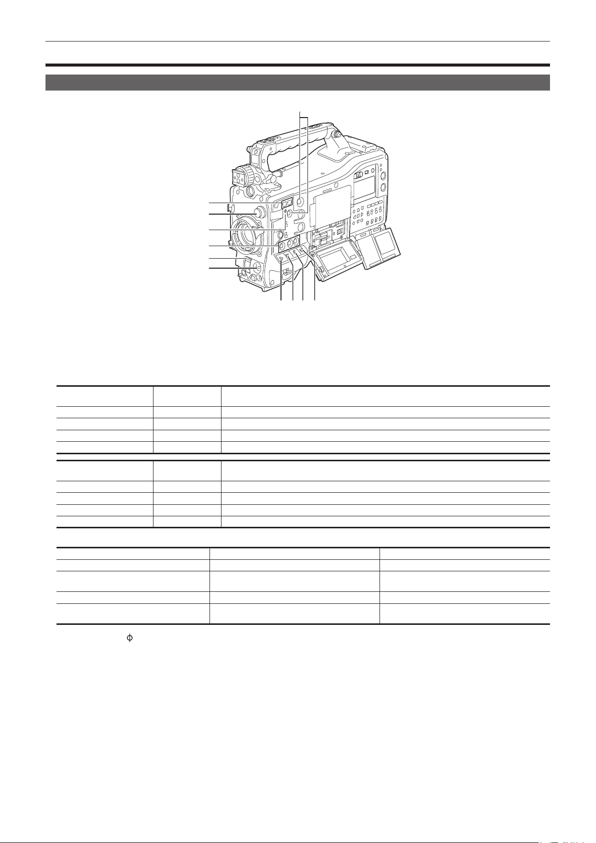
Power supply and accessory mounting section
4 5 6 7 8 1
14
13
15
20
16 17 11
18
19
3
9
11
2
10
12
10
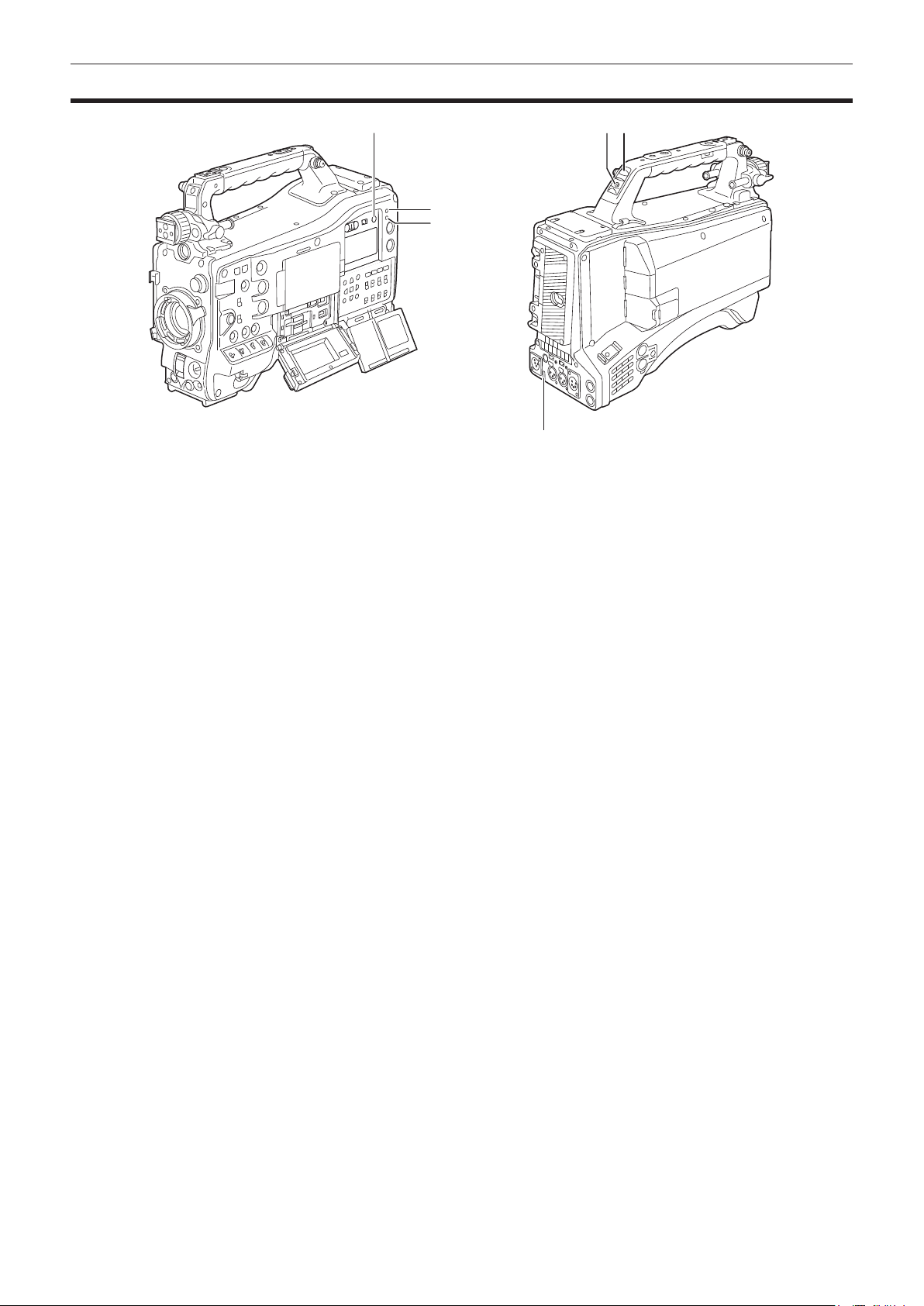
1 Power switch
Switches between power on/standby.
To turn on, set the power switch to < j > (ON). To set to standby, set the power switch to < h > (standby).
@
NOTE
t Even when the power switch is set to the < h > (standby) position, the camera is not shut off from the main power.
2 Viewnder left/right positioning ring
To adjust the left/right position of the viewnder, loosen this ring, and slide the viewnder to the left or right to adjust it to an easy-to-view position.
After adjustment, turn in the <LOCK> direction and rmly clamp.
3 <VF> terminal
Mount the viewnder AG-CVF15G (optional), AJ-CVF50G (optional), etc.
4 Mount cap
Raise the lens lever to remove the cap. Replace the cap when the lens is not mounted.
5 Cable holders
Fix the cables for lens or microphone.
6 Lens mount
Mounts the 2/3-inch bayonet lens.
7 Tripod mount
Attaches the tripod adaptor SHAN-TM700 (optional). (bottom)
8 Lens lever
After mounting the lens to the lens mount, tighten the lens lever to secure the lens.
9 <LIGHT> switch
Select how to turn on/off the video light connected to the <LIGHT> terminal.
<AUTO>: When the video light is left turned on, the light is illuminated at the same time that recording starts on the camera and goes out at the
same time that recording stops.
<MANUAL>: The light is illuminated according to whether the video light is turned on/off.
10 Viewnder front/back positioning lever
To adjust the front/back position of the viewnder, loosen this lever, and slide the viewnder to the front or back to adjust it to an easy-to-view
position. After adjustment, turn in the <LOCK> direction and rmly clamp.
11 Shoulder strap mounting section
Mounts the supplied shoulder strap. (page 44)
12 Battery release lever
Used when removing the battery from the camera.
13 Battery holder
Mounts the Anton/Bauer battery (optional).
14 <DC IN> terminal
This is the input terminal for the external power supply. Connect to the external DC power supply.
15 <DC OUT> terminal
This is the DC12 V power supply output terminal. It provides a maximum current of 1.5 A.
@
NOTE
t Make sure that polarity is correct before connecting an external device. Doing so may result in a malfunction.

– 21 –
Chapter 2 Description of Parts — Power supply and accessory mounting section
16 Accessory mounting holes
Attaches accessories.
Do not attach anything other than an accessory.
f Mounting hole size
-1/4-20 UNC (screw length 10 mm or shorter)
-3/8-16 UNC (screw length 10 mm or shorter)
17 Light shoe
Attaches the video light, etc.
f Mounting hole size
1/4-20 UNC (screw length 6 mm or shorter)
18 <LIGHT> terminal
Connect a video light 50 W or less.
The remaining battery level drops sharply when the video light is illuminated. When using a video light, using a battery of 90 Wh or more is
recommended.
19 Microphone holder mounting section
Mounts the microphone holder AJ-MH800G (optional).
20 <LENS> terminal
Connects the lens connection cable. For details of the lens used, refer to the Operating Instructions for the lens.
– 22 –
Chapter 2 Description of Parts — Audio (input) function section
Audio (input) function section
8 109
1
6
2
4
3
11
5
7
1 <F.AUDIO LEVEL> dial
Adjusts the recording level of the audio channel selected in the [AUDIO] menu → [REC CH SETTINGS] → [VOL. SELECT] when the <AUDIO
SELECT CH1/3>/<AUDIO SELECT CH2/4> switch is set to <MANU>.
f Set whether to enable the <F.AUDIO LEVEL> dial at the [AUDIO] menu → [REC CH SETTINGS] → [FRONT VOL. CH1] to [FRONT VOL. CH4].
2 <AUDIO LEVEL CH1/3>/<AUDIO LEVEL CH2/4> dial
Adjusts the recording level of the audio channel when the <AUDIO SELECT CH1/3>/<AUDIO SELECT CH2/4> switch is set to <MANU>.
<AUDIO LEVEL CH1/3> dial: Adjusts the recording level of the audio channel 1 or the audio channel 3.
<AUDIO LEVEL CH2/4> dial: Adjusts the recording level of the audio channel 2 or the audio channel 4.
f Select the audio channel to adjust with the dial in the [AUDIO] menu → [REC CH SETTINGS] → [VOL. SELECT].
f Dial is equipped with a lock mechanism. Adjust by turning the dial while pressing it in.
3 <AUDIO IN CH1>/<AUDIO IN CH2>/<AUDIO IN CH3>/<AUDIO IN CH4> switch
Selects the audio signal to input to the audio channel 1 to audio channel 4.
<FRONT>: Inputs the audio signal of the microphone connected to the <MIC IN> terminal.
<W.L.>: Inputs the audio signal from the wireless microphone receiver.
<REAR>: Inputs the audio signal from the audio device connected to the <AUDIO IN CH1/3> terminal or the <AUDIO IN CH2/4> terminal.
@
NOTE
t When the stereo microphone AJ-MC900G (optional) is used, set both <AUDIO IN CH1> and <AUDIO IN CH2> (or <AUDIO IN CH3> and <AUDIO
IN CH4>) to <FRONT>.
L CH is recorded to the audio channel 1 or the audio channel 3, and R CH is recorded to the audio channel 2 or the audio channel 4, respectively.
4 <AUDIO SELECT CH1/3>/<AUDIO SELECT CH2/4> switch
Select the audio channel to adjust in the [AUDIO] menu → [REC CH SETTINGS] → [VOL. SELECT].
<AUDIO SELECT CH1/3> switch: Switches the method to adjust the recording level for the audio channel 1 or audio channel 3 with
<AUTO>/<MANU> (automatic/manual).
<AUDIO SELECT CH2/4> switch: Switches the method to adjust the recording level for the audio channel 2 or audio channel 4 with
<AUTO>/<MANU> (automatic/manual).
5 Wireless microphone slot
Mount the UniSlot wireless microphone receiver (optional).
6 <LINE>/<MIC> selector switch
Switches the audio signal input from the <AUDIO IN CH1/3>/<AUDIO IN CH2/4> terminal.
<LINE>: Inputs audio signals from line-input audio equipment.
<MIC>: Inputs audio signals from the microphone.
7 Microphone input power selector switch
Turns on/off the power supply to the microphone connected to the <AUDIO IN CH1/3>/<AUDIO IN CH2/4> terminal.
<+48V>: Supplies +48 V power to the microphone.
<OFF>: Does not supply power to the microphone.
@
NOTE
t When microphone input <+48V> is set and microphones are not connected to the <AUDIO IN CH1/3> and <AUDIO IN CH2/4> terminals, low-
frequency noise may occur. This is not a problem when a microphone is connected.
t When the [AUDIO] menu → [INPUT SETTINGS] → [REAR MIC POWER] → [ON] is not set, power is not supplied regardless of the switch
position.
8 <AUDIO IN CH1/3>/<AUDIO IN CH2/4> terminal
Connects the audio equipment or the microphone.
<AUDIO IN CH1/3> terminal: Inputs the audio signal to the audio channel 1 and the audio channel 3.
<AUDIO IN CH2/4> terminal: Inputs the audio signal to the audio channel 2 and the audio channel 4.
9 Cable holder
Fixes HDMI cables, etc.

– 23 –
Chapter 2 Description of Parts — Audio (input) function section
10 Cable holder
Fixes the cables for lights or microphone.
11 <MIC IN> terminal
Connects an external microphone (optional).
f When using the phantom microphone, set to the [AUDIO] menu → [INPUT SETTINGS] → [FRONT MIC POWER] → [ON]. When it is set to [ON]
and a microphone is not connected, low-frequency noise may occur. This is not a problem when a microphone is connected.
– 24 –
Chapter 2 Description of Parts — Audio (output) function section
Audio (output) function section
7
6
3
6
21
4
5
1 <MONITOR> dial
Adjusts the volume of the monitor audio during playback, recording, and recording standby.
2 <ALARM> dial
Adjusts the volume of the alarm from the built-in speaker and earphones.
When set to the minimum position, the alarm cannot be heard.
3 Built-in speaker
EE audio is output during recording, and playback audio is output during playback.
An alarm sound is output in sync with ashing/lighting of the <WARNING> lamp or warning indicator.
Audio from the built-in speaker is automatically muted when earphones are connected to the <PHONES> terminal.
4 <MONITOR SELECT> switch
Selects audio output from the built-in speaker, earphones, and <AUDIO OUT> terminal interlocked with the audio channel selector switch.
<CH1/3>: Outputs audio signal of the audio channel 1 or the audio channel 3.
<ST>: Outputs the stereo audio signal of the audio channel 1 and the audio channel 2, or the audio channel 3 and the audio channel 4. Set to the
MIX signal in the [AUDIO] menu → [OUTPUT SETTINGS] → [MONITOR SELECT] → [MIX].
<CH2/4>: Outputs audio signal of the audio channel 2 or the audio channel 4.
<MONITOR SELECT> switch
Audio channel selector switch
<CH1/2> <CH3/4>
<CH1/3> Audio channel 1 Audio channel 3
<ST> Stereo output from audio channels 1 and 2* Stereo output from audio channels 3 and 4*
<CH2/4> Audio channel 2 Audio channel 4
* Switches between [STEREO] and [MIX] in the [AUDIO] menu → [OUTPUT SETTINGS] → [MONITOR SELECT].
5 Audio channel selector switch
Switches the audio channel output to the built-in speaker, earphones, and <AUDIO OUT> terminal.
<CH1/2>: Outputs audio signal of the audio channel 1 and the audio channel 2.
<CH3/4>: Outputs audio signal of the audio channel 3 and the audio channel 4.
6 <PHONES> terminal
This is a stereo mini jack terminal for the audio monitor earphones.
Same audio is output for both the front and the rear sides.
7 <AUDIO OUT> terminal
Outputs the audio signal recorded in the audio channel 1 to audio channel 4.
f The audio signal to be output is switched with the <MONITOR SELECT> switch.
– 25 –
Chapter 2 Description of Parts — Shooting and recording/playback functions section
Shooting and recording/playback functions section
Shooting and recording (Camera unit)
2
5
4
4
3
6
7 8 9 10
1
1 <SYNCHRO SCAN> button
Adjusts the shutter speed of synchro scan in the synchro scan mode.
Pressing the <−> button slows down the shutter speed. Pressing the <+> button increases the shutter speed.
For example, when shooting a computer monitor, adjust to a position where the noise for the horizontal bar in the viewnder will be reduced.
2 <CC FILTER>/<ND FILTER> dial
Select the lter to suit the luminance or color temperature of the subject.
Position of <CC FILTER>
dial (large diameter)
Setting Description
<A> <3200 K> Sets the color temperature to 3200 K.
<B> <4300 K> Sets the color temperature to 4300 K.
<C> <5600 K> Sets the color temperature to 5600 K.
<D> <6300 K> Sets the color temperature to 6300 K.
Position of <ND FILTER>
dial (small diameter)
Setting Description
<1> <CLEAR> Does not use the ND lter.
<2> <1/4ND> Reduces the amount of light entering the MOS sensor to 1/4.
<3> <1/16ND> Reduces the amount of light entering the MOS sensor to 1/16.
<4> <1/64ND> Reduces the amount of light entering the MOS sensor to 1/64.
Refer to the following table to switch the <CC FILTER> and <ND FILTER> dials according to the shooting conditions.
Shooting conditions <CC FILTER> dial <ND FILTER> dial
Sunset, sunrise, inside studio <A> (<3200 K>) <1> (<CLEAR>)
Outdoors in the clear skies
<B> (<4300 K>) or <C> (<5600 K>) or <D>
(<6300 K>)
<2> (<1/4ND>) or <3> (<1/16ND>)
Outdoors under cloudy skies or in the rain <D> (<6300 K>) <1> (<CLEAR>) or <2> (<1/4ND>)
Clear, bright scenery such as snowy scenery,
tall mountains, seaside
<B> (<4300 K>) or <C> (<5600 K>) or <D>
(<6300 K>)
<3> (<1/16ND>) or <4> (<1/64ND>)
3 Focal plane index <
>
Indicates the focal plane of the MOS sensor.
Use this mark as a reference for measuring the accurate focal distance from the subject.
4 USER button
The function selected by the user can be assigned to the <USER 1> to <USER 5> buttons. Pressing the USER button performs the assigned
function.
5 <SHUTTER> switch
Switches the electronic shutter.
<OFF>: Disables the electronic shutter.
<ON>: Enables the electronic shutter.
<SEL>: Changes the shutter speed.
It is a spring switch. Shutter speed is changed each time pressed toward the <SEL> side.

– 26 –
Chapter 2 Description of Parts — Shooting and recording/playback functions section
6 <AUTO W/B BAL> switch
<AWB>: White balance is automatically adjusted. When this switch is operated with the <WHITE BAL> switch on the side set to <A> or <B>,
adjustment is performed in several seconds and adjustment values are stored in memory.
This is disabled when the <WHITE BAL> switch is set to <PRST>.
<ABB>: Adjusts black balance automatically.
The black shading automatic adjust function can be assigned to this switch when set to the [CAMERA] menu → [SW MODE] → [SHD,ABB SW CTL]
→ [ON].
f The automatic adjustment is cancelled when operation of switch is repeated while auto adjustment is performed. The adjustment values will return
to the values before automatic adjustment was performed.
7 <MARKER SEL>/<MODE CHECK> switch
This is the spring switch to select a maker and check the shooting status of the camera.
<MKR>: Every time this is pressed to the <MKR> side, the marker display on the viewnder switches in the order of [A] marker, [B] marker, and no
display.
When the power is turned on, the status before the power was turned off is applied.
<MCK>: Every time this is pressed to the <MCK> side, display is switched in the order of STATUS screen, !LED screen, FUNCTION screen, AUDIO
screen, CAC screen, SWITCH screen, NETWORK screen, and camera image screen. This does not affect the output signals from the camera. The
display goes out in about ve seconds. When the switch is continued to be pressed toward the <MCK> side, the selected screen remains displayed.
8 <GAIN> switch
Switches the video amplier gain according to the lighting conditions when shooting.
f Set the gain value for <L>/<M>/<H> in the [SCENE FILE] menu → [LOW SETTING]/[MID SETTING]/[HIGH SETTING] → [MASTER GAIN] in
advance.
f The factory setting is L=0 dB, M=6 dB, H=12 dB.
9 <OUTPUT>/<AUTO KNEE> switch
Select the video signals output to the memory, viewnder and video monitor from the camera unit.
<CAM>/<ON>: Video captured on the camera is output and the auto knee function is activated.
Instead of the auto knee function, the dynamic range stretcher (DRS) function can be assigned.
<CAM>/<OFF>: Video captured on the camera is output and the auto knee function is not activated.
The knee point is xed to the level set in the [SCENE FILE] menu → [KNEE SETTING] → [KNEE MASTER POINT].
<BARS>/<OFF>: The color bar signal is output. The auto knee function is not activated.
The color bar signal can be selected from the two types in the [OTHERS] menu → [COLOR BARS] → [COLOR BARS TYPE].
@
NOTE
t As the factory setting, test signals are output to all audio channels 1 to 4 when the <OUTPUT>/<AUTO KNEE> selector switch is set to <BARS>.
Whether to output the test signal or not can be changed in the [OTHERS] menu → [COLOR BARS] → [TEST TONE].
t Auto knee function
When you adjust levels to shoot people or scenery against a background with high luminosity, the background will be totally white-out, with
buildings and other objects blurred. In such a case, the auto knee function reproduces the background clearly.
The auto knee function is effective when shooting the following scenes:
- The subject is a person positioned in the shade under a clear sky.
- The subject is a person inside a car or a building, and you also want to capture the background visible through a window.
- The subject is a high-contrast scene.
10 <WHITE BAL> switch
Switches the white balance adjustment method.
<PRST>: Set the switch to this position when there is no time to adjust the white balance.
f The factory setting is 3200 K.
f Can be changed to an arbitrary color temperature with the [CAMERA] menu → [WHITE BALANCE MODE] → [W.BAL VAR].
<A>/<B>: When the <AUTO W/B BAL> switch is pressed to the <AWB> side, the white balance is automatically adjusted and the adjusted value is
saved in memory A or memory B.
The auto tracking white balance (ATW) function can be assigned to the <WHITE BAL> switch with the [CAMERA] menu → [WHITE BALANCE
MODE] → [ATW].
– 27 –
Chapter 2 Description of Parts — Shooting and recording/playback functions section
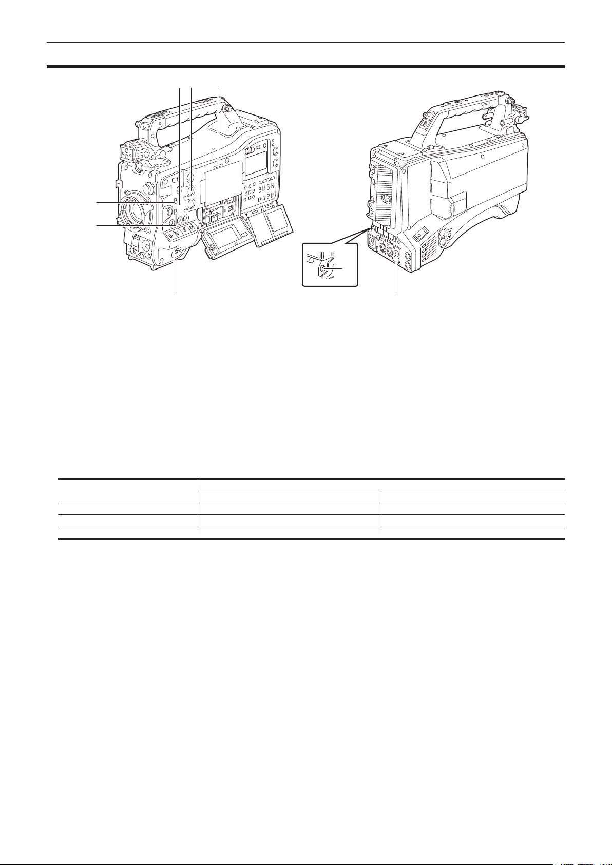
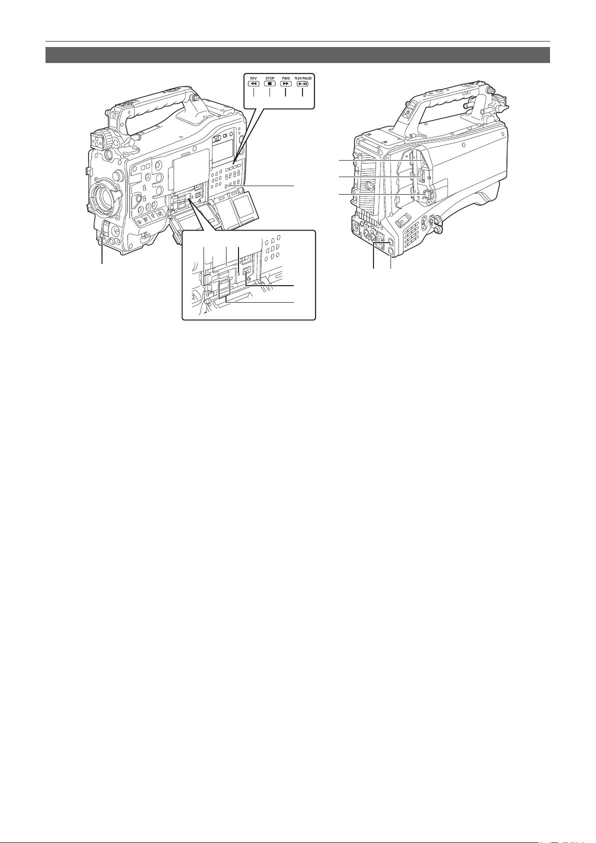
Shooting and recording/playback functions section (Recording unit)
1
1514
11
12
3
13
6 7 8 9
2
2
4
10
5
1 <REC> button
Recording is started by pressing the <REC> button. Recording is stopped by pressing this button again.
Performs the same operation as the <VTR> button of the lens to be attached.
2 Card access lamp 1/card access lamp 2/card access lamp 3
Indicates the access status of recording and playback of the memory card.
3 Card slot 1
This is a card slot only for expressP2 card.
4 <USB DEVICE> terminal
In the USB device mode, the camera can be connected to the computer by the USB type C cable to transfer data. In this case, recording playback
operations and camera shooting are not possible.
5 Card slot 2/card slot 3
These are card slots for microP2 card and SD card.
6 <REV (%)> button
It will perform fast-reverse playback when this is pressed during playback.
It will playback from the start of the clip when this is pressed while paused.
7 <STOP (()> button
Press this button to stop playback.
8 <FWD ())> button
It will perform fast playback when this is pressed during playback.
It will play back from the start of the next clip when this is pressed while paused during a playback.
9 <PLAY/PAUSE (=/&)> button
Plays back a clip.
Playback is paused when this is pressed during the playback.
10 <SDI OUT 2 CHARACTER> switch
Controls the superimposing of characters into the video output from the <SDI OUT2> terminal.
Controls the superimposing of characters into the video output from the <HDMI> terminal when the [VIDEO OUT/LCD/VF] menu → [HDMI OUT] →
[SIGNAL SEL] → [SDI OUT2] is set.
<ON>: Superimposes the character.
<OFF>: Does not superimpose the character.
11 <USB2.0 HOST> terminal
Can connect via wireless LAN when the wireless module (optional) compatible to camera is mounted.
In addition, connecting the USB cable and iPhone/iPad or Android device will enable to connect to the network using USB tethering.
12 <HDMI> terminal
This is the output terminal for videos.
Output signal can be switched with the [VIDEO OUT/LCD/VF] menu → [HDMI OUT] → [SIGNAL SEL].
[SDI OUT1(2160p)]: Follows the setting of the output signal from the <SDI OUT1> terminal.
[SDI OUT2]: Follows the setting of the output signal from the <SDI OUT2> terminal.
Setting for superimposing of characters can be switched in the [VIDEO OUT/LCD/VF] menu → [HDMI OUT] → [SIGNAL SEL].
13 <LAN> terminal
Connects the 1000BASE-T/100BASE-TX/10BASE-T LAN cable.
Use Category 7 LAN cable.

– 28 –
Chapter 2 Description of Parts — Shooting and recording/playback functions section
14 <SDI OUT1> terminal
This is the output terminal only for SDI.
Select an output signal in the [VIDEO OUT/LCD/VF] menu → [SDI OUT1] → [OUT FORMAT].
Superimposing of characters is set in the [VIDEO OUT/LCD/VF] menu → [SDI OUT1] → [SDI OUT CHAR].
15 <SDI OUT2> terminal
This is the video output terminal for the monitor.
Select an output signal in the [VIDEO OUT/LCD/VF] menu → [SDI OUT2] → [OUT FORMAT].
Superimposing of characters can be set with the <SDI OUT 2 CHARACTER> switch independently of the <SDI OUT1> terminal.
@
NOTE
t Use 5C-FB or higher cable to connect to the <SDI OUT1>/<SDI OUT2> terminals.
– 29 –
Chapter 2 Description of Parts — Menu operation section and thumbnail operation section
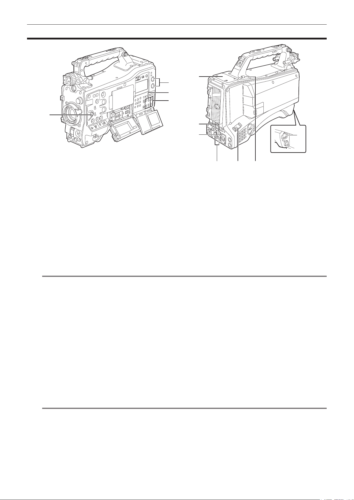
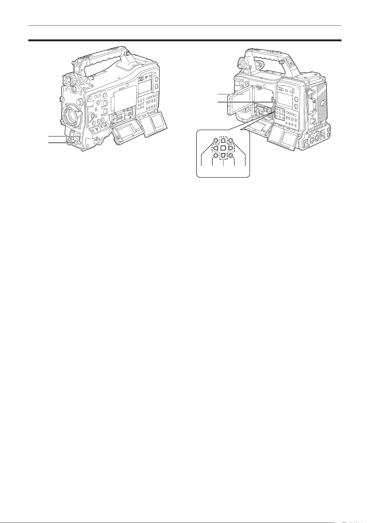
Menu operation section and thumbnail operation section
2
1
4
3
5 1 6 7 8
1 <MENU> button
Press the <MENU> button to display menu on the viewnder screen. Press it again to return to the previous display.
There are two <MENU> buttons at the front and the rear, and both perform the same operation.
2 Jog dial button
With the menu open, navigates, selects, or sets the menu.
3 LCD monitor
Displays the camera image or replayed image. The thumbnail and status can also be displayed.
f The quality of the image displayed in this monitor is different from the quality of the image that is actually recorded/output to the camera.
Bear this in mind especially in the following case:
-When set to the [SCENE FILE] menu → [GAMMA MODE SEL] → [HLG]
f If the battery is removed or the external DC power plug is removed while the power is on, a residual image might remain in the LCD screen. This is
not a malfunction. It will disappear if the screen is left as it is.
f At lower temperatures, residual images sometimes appear to increase on the screen. This is not a malfunction.
4 <OPEN> button
This is used to open the LCD monitor.
5 <THUMBNAIL> button
Press this button to display the thumbnail screen on the LCD monitor and viewnder screen. Press it again to return to the regular display.
6 Cursor operation button
This is used for setting time codes or user bit values, and selecting thumbnails or operating menus.
This is used for selecting an item or changing the setting when the menu is displayed.
Operate the cursor with the four triangular buttons, and set with the <SET> button at the center.
7 <EXIT> button
Restore the display to the previous state while the menu or settings screen is displayed.
8 <SHIFT> button
This is used together with other button being pressed simultaneously.
f The [OPTION] menu is displayed when the <MENU> button is pressed together with the <SHIFT> button.
– 30 –
Chapter 2 Description of Parts — Time code section
Time code section
1 3
4
2
6
5
1 <HOLD> button
The time data indication on the counter display area is retained from the moment when this button is pressed. However, the time code generator
continues to advance. Press the button again to release the retained state.
This is used when you want to know the time code of the recorded scene or the counter data of the counter display.
2 <RESET> button
Resets the counter data of the counter display to [00:00:00:00].
To return the real time data to factory settings, set the <TCG> switch to <SET> and press the <RESET> button. Both the time code data and user
bits data are reset to 0.
3 <DISPLAY> switch
Displays the counter data, time code, or user bits in the counter of the display window according to the setting position of the <DISPLAY> switch and
the <TCG> switch.
<UB>: Displays the user bits.
<TC>: Displays the time code.
<COUNTER>: Displays the counter data.
4 <TCG> switch
Sets the advance mode for the built-in time code generator.
<F-RUN>: Use this to advance the time code continuously regardless of the memory card recording operation. Set to this position to, for example,
set the time code to the current time or externally lock the time code.
<SET>: Use this to set the time code or user bits.
<R-RUN>: Use this to advance the time code only when recording. The time codes will remain continuous when recording continuously between
memory cards.
5 <GENLOCK IN> terminal
Inputs reference signals when the camera unit is genlocked or when the time code is externally locked.
6 <TC IN/OUT> terminal
Connects to an external equipment and output/input a time code.
Inputs the standard time code when locking the time code with an external equipment.
Input and output are set in the [RECORDING] menu → [TC/UB] → [TC IN/OUT SEL].
– 31 –
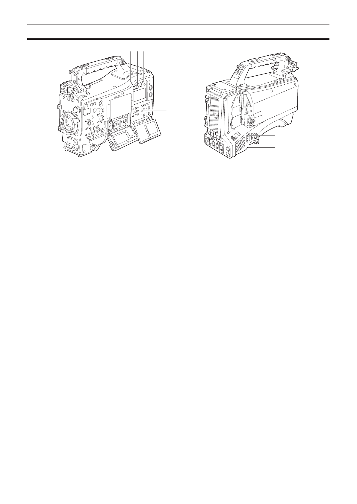
Chapter 2 Description of Parts — Warning and status display section
Warning and status display section
2
3
1 5
6
4
1 <BRIGHT> button
Controls the brightness of the display window.
The brightness is switched in two levels every time the <BRIGHT> button is pressed.
Regardless of the previous setting, it will display in dark setting when the power is turned on.
2 <WARNING> lamp
Flashes or illuminates if something unusual occurs in the memory.
3 <STREAMING> lamp
Illuminates in orange when the camera is streaming.
4 Back tally switch
Controls the action of the back tally lamp and the rear tally lamp.
<ON>: Enables the back tally lamp and the rear tally lamp.
<OFF>: Disables the back tally lamp and the rear tally lamp.
5 Back tally lamp
When the back tally switch is set to <ON>, the lamp acts in the same way as the front tally lamp at the viewnder.
6 Rear tally lamp
When the back tally switch is set to <ON>, the lamp acts in the same way as the back tally lamp.
– 32 –
Chapter 2 Description of Parts — Display inside the display window
Display inside the display window
Display of remaining memory card capacity, remaining battery level, and recording level
1 2
NDF
COUNTER
MEDIA
E F
SLAVE HOLD
GPS
P
-
REC
BATT
E F
3
1
2
5
4
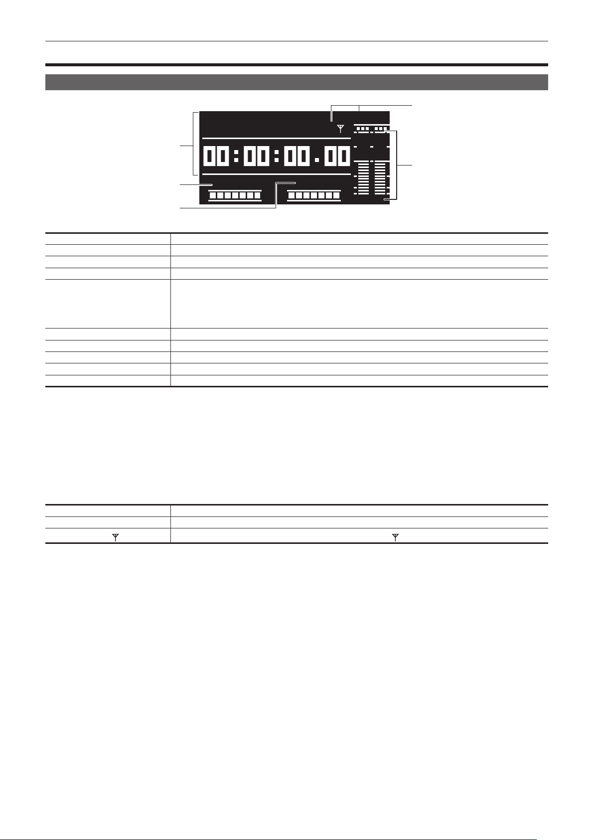
1 Time code indications
[NDF] Displayed when the time code is in the non-drop frame mode.
[DF] Displayed when the time code is in the drop frame mode.
[SLAVE] Displayed when the time code is externally locked.
[HOLD] Displayed when the time code generator/read value is held.
[COUNTER]/[CLIP]
Displays as follows while playing back and not playing back when <COUNTER> is selected by the <DISPLAY> switch.
While playing back: Displays [CLIP].
Not playing back: Content of display differs depending on the [RECORDING] menu → [REC COUNTER] setting.
f [TOTAL]: Displays [COUNTER].
f [CLIP]: Displays [CLIP].
[TCG] Displays when <TC> is selected by the <DISPLAY> switch and the TC generator value (h:min:sec:frm) is displayed.
[TCR] Displays when <TC> is selected by the <DISPLAY> switch and the TC read value is displayed.
[UBG] Displays when <UB> is selected by the <DISPLAY> switch and the UB generator value is displayed.
[UBR] Displays when <UB> is selected by the <DISPLAY> switch and the UB reader value is displayed.
Time counter display Displays the time code/user bits/counter data.
2 Remaining memory card capacity display bar
Displays the remaining memory card capacity with seven segments.
The remaining memory card capacity time indicated by one segment is approximately three minutes. Segments go out one by one approximately
every three minutes.
3 Remaining battery level display bar
Displays the remaining battery level with seven segments.
When a battery with a digital indication (% indication) is used, all seven segments up to the [F] position light if the remaining battery level is 70% or
higher.
When the remaining battery level falls below 70%, the segments go out one by one for each 10% drop.
4 Mode display
[P-REC]
Displays when set to the [RECORDING] menu → [PRE REC] → [ON].
[i-REC]
Displays when set to the [RECORDING] menu → [REC FUNCTION] → [REC MODE] → [INTERVAL].
[GPS
] [GPS] is displayed when the [OTHERS] menu → [GPS] → [ON] is set. illuminates after positioning is complete.
5 Audio channel level meter
When the audio channel selector switch is set to <CH1/2>, [1] and [2] indicating the corresponding audio channels are displayed, and the recording
level of the audio channel 1 and the audio channel 2 is displayed.
When the audio channel selector switch is set to <CH3/4>, [3] and [4] indicating the corresponding audio channels are displayed, and the recording
level of the audio channel 3 and the audio channel 4 is displayed.

Before you use the camera, mount the battery and lens following the procedures in this chapter. The mounting of accessories is also described in this
chapter.
Chapter 3 Preparation
– 34 –
Chapter 3 Preparation — Power supply
Power supply
A battery or an external DC power supply can be used as the power supply for the camera.
To use a battery
Connection of the following batteries to the camera has been veried.
r Anton/Bauer battery
Dionic/Hytron/Titon/Digital series
@
NOTE
t Other batteries are supported by selecting the [OTHERS] menu → [BATTERY] → [ONBOARD BATTERY] → [BATTERY SEL] → [other]. Use of
batteries that are already veried as connectable to the camera is recommended.
t Before you use a battery, charge it with a battery charger. (For details on charging, refer to each instruction operation.)
t When using the light (Ultralight 2), using a battery of 90 Wh or more is recommended.
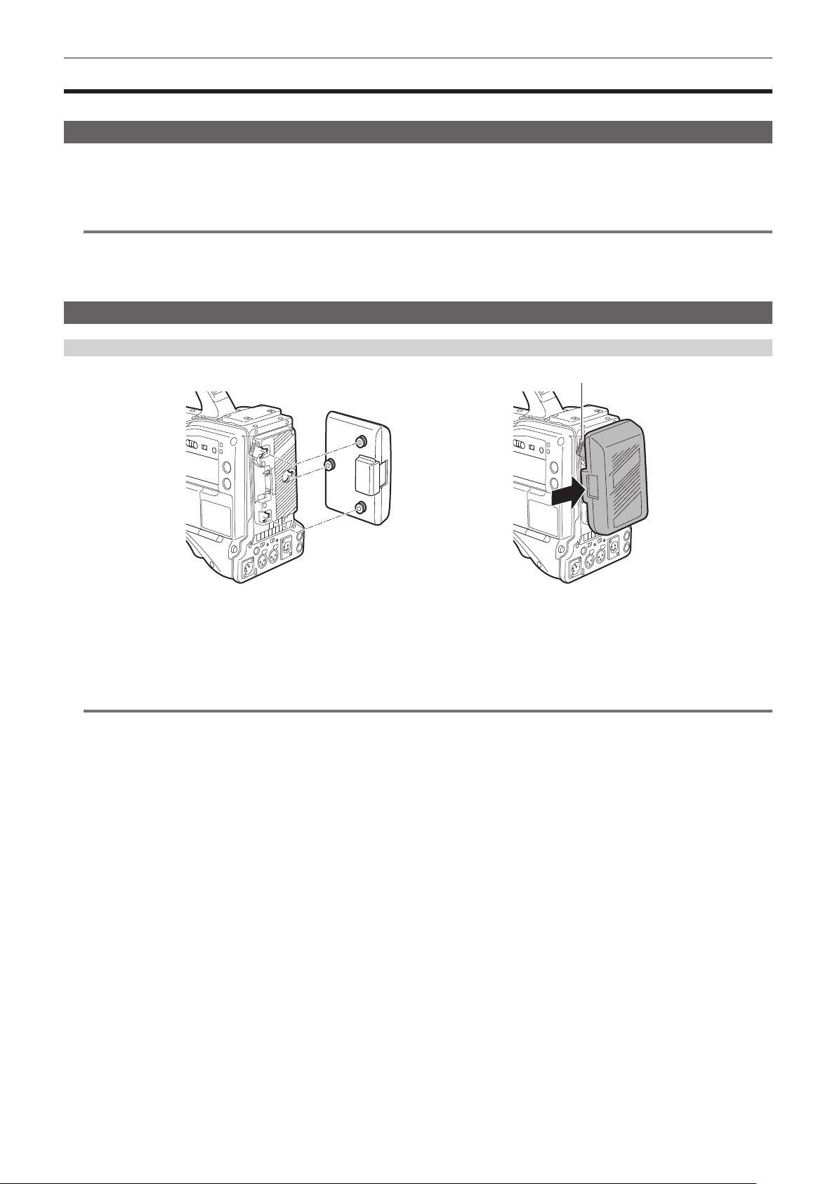
Attaching and setting the battery
Using Anton/Bauer batteries
Anton/Bauer battery
Release lever
1
Mount the Anton/Bauer battery.
2
Insert the battery terminal and slide in the direction of the arrow.
3
Set the battery type.
Select the type of the battery in the [OTHERS] menu → [BATTERY] → [ONBOARD BATTERY] → [BATTERY SEL].
@
NOTE
t When removing the battery, keep the release lever of the battery holder completely down, slide the battery in the opposite direction of when you
mounted it.
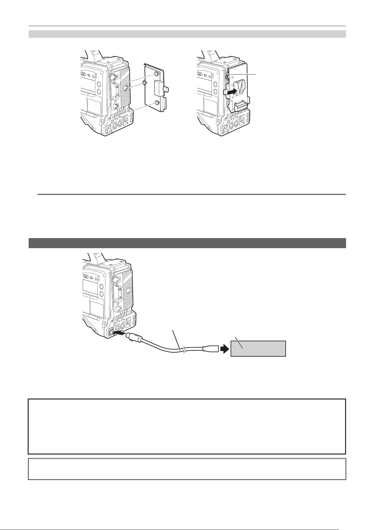
– 35 –
Chapter 3 Preparation — Power supply
Using V-mount type batteries
Mount the V-mount type battery plate. As shown in the gure, insert and slide in the direction of the arrow.
Release lever
1
Mount the V-mount type battery plate.
2
Slide in the direction of the arrow.
3
Set the battery type.
f Set the type of the battery in the [OTHERS] menu → [BATTERY] → [ONBOARD BATTERY] → [BATTERY SEL].
@
NOTE
t Contact your dealer for information about the V-mount type battery plate.
t When the V-mount type battery plate is used, % (percent) is not displayed even if batteries with a battery level indicator function are used.
t When removing the plate, keep the release lever of the battery holder completely down, slide the plate in the opposite direction of when you mounted
it.
t When using a battery that is not in the [BATTERY SEL], set to [other], and set [FULL VOLT]/[NEAR END VOLT]/[END VOLT] according to the
characteristics of the battery.
Using external DC power supply
<DC IN> terminal
DC cable
External DC power supply
1
Connect the external DC power supply to the <DC IN> terminal of the camera.
2
Turn on the power switch of the external DC power supply (if the external DC power supply has a power switch).
3
Turn the power switch of the camera to < j > (ON).
r External DC power supply
Connect after making sure that the output voltage of the external DC power supply is compatible with the rated voltage of the camera.
Select an output amperage for the external DC power supply with a margin above the total amperage of the connected devices.
The total amperage of connected devices can be calculated with the following formula.
Total power consumption ÷ Voltage
When the power of the camera is turned on, inrush current is generated. Insufcient power supply when turning on the power may cause a malfunction. We
recommend that you use an external DC power supply that can assure double the capacity of the total power consumption of the camera and connected devices
that are turned on by interlock when the power of the camera is turned on (such as lenses, wireless microphone receivers). For the DC cable, use a dual-core
shielded wire of AWG18 (nominal cross section area 0.824 mm
2
) or thicker.
f Make sure of the pin alignment of the DC output terminal of the external DC power supply and the camera <DC IN> terminal, and connect the polarity
correctly.
If the +12 V power supply is connected to the GND terminal in error, it may cause re or malfunction.

– 36 –
Chapter 3 Preparation — Power supply
DC IN
1 GND
2 NC
3 NC
4
+12 V
Panasonic Parts No.: K1AA104H0038
Manufacturer Parts No.: HA16RX-4P (SW1) (76) (Hirose Electric Co.)
@
NOTE
t When both the battery and the external DC power supply are connected, the power supply from the external DC power supply has priority. The battery
may be removed while using the external DC power supply.
t When using an external DC power supply, always turn the power switch of the external DC power supply on before turning the power switch of the
camera to < j > (ON). If the operations are performed in reverse, the camera may malfunction because the external DC power supply output voltage
rises too slowly.
t When power is supplied from the <DC IN> terminal, the light circuit does not function. The light circuit can be used only when power is supplied from
the Anton/Bauer battery plate.
t When connecting a battery to the <DC IN> terminal, set to the [OTHERS] menu → [BATTERY] → [DC IN SOURCE] → [BATTERY], and then set the
voltage with the [OTHERS] menu → [BATTERY] → [DC IN BATTERY]. However, in that case, % display is not possible for batteries with a battery
level indicator function.
t Turn the power off of the camera before attaching or removing the lens cable.
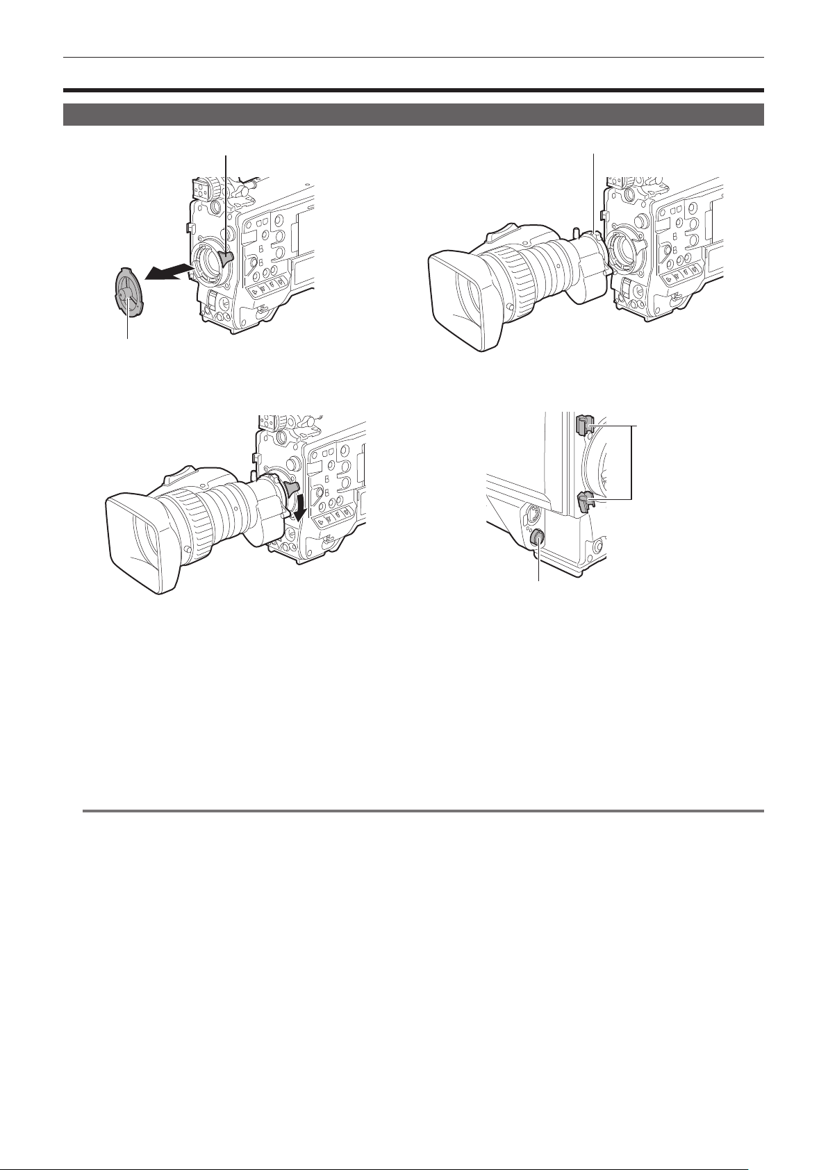
– 37 –
Chapter 3 Preparation — Mounting and adjusting the lens
Mounting and adjusting the lens
Mounting the lens
Fig. 1
Fig. 4
Fig. 2
Fig. 3
Lens lever
Mount cap
Center mark
Cable holders
<LENS> terminal
1
Raise the lens lever and remove the mount cap. (Fig. 1)
2
Align the indentation at the top center of the lens mount with the center mark of the lens to mount the lens. (Fig. 2)
3
Lower the lens lever to firmly clamp the lens. (Fig. 3)
4
Secure the cable through the cable holder and connect it to the <LENS> terminal. (Fig. 4)
5
Perform lens flange back adjustments.
For details, refer to “Adjusting lens ange back” (page 38).
@
NOTE
t For handling the lens, refer to the lens operating instructions.
t For details regarding the current from the <LENS> terminal, refer to “Details of the connector signals” (page 240).
t When the lens is removed, install the mount cap to protect the device.
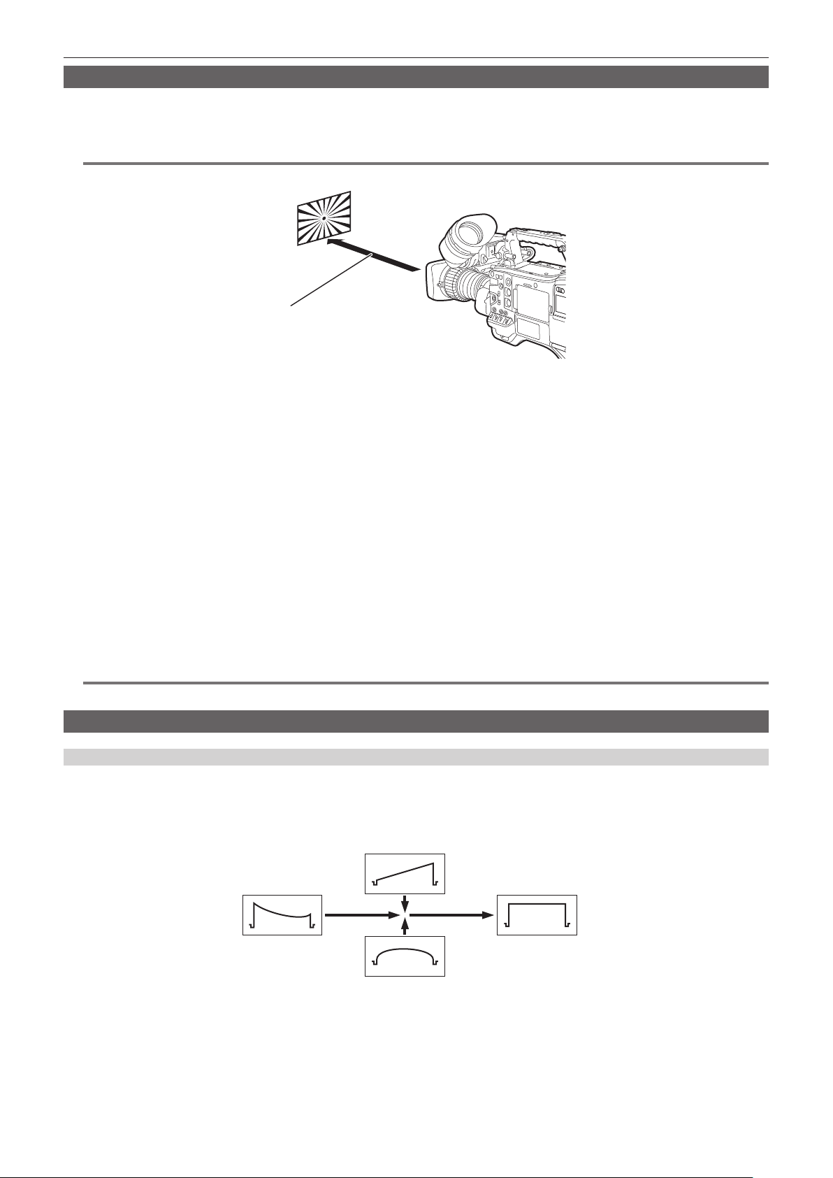
– 38 –
Chapter 3 Preparation — Mounting and adjusting the lens
Adjusting lens ange back
If images are not clearly focused at both telephoto and wide-angle positions during zoom operations, adjust the ange back (distance from the lens
mounting surface to the image formation surface).
Once adjusted, the ange back does not need to be readjusted until the lens is changed.
@
NOTE
t Refer to the lens operating instructions for guidance on adjustment methods and positions of lens parts.
Approximately 3 m
1
Mount the lens on the camera.
Make sure to connect the lens cable.
2
Set the lens iris to manual, and fully open the iris.
3
Place the flange back adjustment chart approximately 3 m from the lens and adjust the lighting on the chart to obtain an
appropriate image output level.
If the image level is too high, use the lters or the shutter.
4
Loosen the F.f (Flange focus) ring clamping screw.
5
Set the zoom ring to the telephoto end position, either manually or by electric drive.
6
Aim the lens at the flange back adjustment chart and turn the distance ring to bring the chart into focus.
7
Set the zoom ring to the wide-angle end position and turn the F.f (Flange focus) ring to bring into focus.
At this time, do not move the distance ring.
8
Repeat steps 5 to 7 until the lens is in focus at both the telephoto and wide-angle positions.
9
Firmly tighten the F.f (Flange focus) ring clamping screw.
@
NOTE
t F.b (Lens ange back) ring may be indicated on some lenses as the F.f (Flange focus) ring.
White shading compensation function
Adjusting the white shading
This is a method of combining the sawtooth shaped waveform and parabola waveform to compensate to a atter waveform based on the respective R,
G and B waveforms of the video signal.
We recommend adjusting the R, G and B waveforms in the horizontal and vertical directions while monitoring them on the waveform monitor.
Before adjusting the white shading, make sure to cancel [DS.GAIN] and [D.ZOOM] set to the USER button.
H SAW
H PARA
Before white shading
compensation
After white shading
compensation
1
Set the camera for adjustment.
1) Mount the lens on the camera.
f Make sure to connect the lens cable.
2) Set the <SHUTTER> switch to <OFF>, and the <GAIN> switch to <L> (0 dB).
3) If the lens is equipped with an extender function, release the extender function.

– 39 –
Chapter 3 Preparation — Mounting and adjusting the lens
4) Confirm that the [SCENE FILE] menu → [GAMMA MODE SEL] → [HD] is set.
5) Confirm that the [VIDEO OUT/LCD/VF] menu → [EI ASSIST] is set to as follows.
f Change the setting if it is different.
[ZEBRA1 DETECT]: [70%]
[ZEBRA2 DETECT]: [85%]
[ZEBRA2]: [SPOT]
6) Set the <ZEBRA> switch in the viewfinder to <ON>.
2
Set the screen.
1) Shoot a white sheet of paper with no unevenness of color for the whole screen.
2) Set the lens aperture to manual, and adjust it so that the zebra pattern covers the whole viewfinder screen.
f Make sure that the lens aperture control is between F4 to F11.
f Adjust the position of the lighting because the zebra pattern will not cover the whole screen if there is any unevenness in the lighting.
f Make adjustments to avoid several light sources of different color temperature (e.g. uorescent lights and halogen lamp) from illuminating on
the white paper.
3
Adjust the white balance/black balance.
1) Set the <WHITE BAL> switch to <A> or <B>, and use the <AUTO W/B BAL> switch to adjust white balance automatically (AWB).
2) Use the <AUTO W/B BAL> switch to adjust black balance automatically (ABB).
3) Use the <AUTO W/B BAL> switch to adjust white balance automatically (AWB) again.
4
Perform the steps 2 - 2) again.
5
Adjust white shading.
Set all of the following items in the [CAMERA] menu → [WHITE SHADING] to generate a waveform as at as possible.
f [R H SAW]
f [R H PARA]
f [R V SAW]
f [R V PARA]
f [G H SAW]
f [G H PARA]
f [G V SAW]
f [G V PARA]
f [B H SAW]
f [B H PARA]
f [B V SAW]
f [B V PARA]
6
If the lens is equipped with an extender function, turn on the extender function and repeat steps 2 to 5.
Adjustment values are stored on the camera as a single lens le data using two patterns for when the lens is equipped and not equipped with the
extender function.
Adjustment values are saved in memory, so there is no need to re-adjust white shading even after turning the camera off.
@
NOTE
t Coloring may occur in the vertical direction near where the lens aperture is open (OPEN) even when the white shading has been adjusted, but this is
something that is inherent to optical systems. This is not a malfunction.
t Since uorescent lights, mercury lamps, and other such kinds of lighting tend to icker, use a light source which is less subject to ickering such as
sunlight or a halogen lamp.
t Make adjustments to the position of the lighting, etc. when the lens aperture is not between F4 and F11.
t Make sure to leave the <SHUTTER> switch at <OFF>.
Chromatic aberration compensation function (CAC)
The chromatic aberration compensation function minimizes color smearing in peripheral images. The registration error that is caused mainly due to
slight chromatic aberration that cannot be completely compensated by the lens is automatically compensated by the camera.
The chromatic aberration compensation function will automatically start to operate when a chromatic aberration compensation function compatible lens
is mounted.

– 40 –
Chapter 3 Preparation — Mounting and adjusting the lens
What is lens chromatic aberration?
B
G
R
“Chromatic aberration” here refers to zoom factor chromatic aberration. Zoom factor chromatic aberration occurs since the diffraction ratio of a lens
differs according to red (R)/green (G)/blue (B). Chromatic aberration on the lens itself is compensated for, but still remains in the periphery, in particular.
Also, this chromatic aberration occurs on zoom lens due to a complex relationship between zoom ratio, aperture and focal distance. In image terms, this
is registration error.
Chromatic aberration compensation function
Mount the chromatic aberration compensation function compatible lens to compensate the chromatic aberration. The chromatic aberration
compensation function will automatically operate. Or, store the chromatic aberration characteristics of the lens regarding zoom ratio, aperture, and focal
distance to the camera beforehand. Connect a lens that matches those chromatic aberration characteristics, and perform compensation matched to the
zoom ratio, aperture and focal distance of that lens.
@
NOTE
t For details on additions and modications to lenses compatible with the chromatic aberration compensation function, visit the support desk at the
following website:
https://pro-av.panasonic.net/
Operation of chromatic aberration compensation function
Operate in following steps when a chromatic aberration compensation function compatible lens is mounted to the camera.
1
Mount the lens on the camera, and connect the lens connector to the camera.
2
Set to the [CAMERA] menu → [CAC ADJ.] → [CAC CONTROL] → [ON].
The chromatic aberration compensation data is read from the lens and the chromatic aberration compensation function will operate automatically
when the camera is turned on.
If the lens model number stored on the camera matches the model number of the connected lens, the chromatic aberration data stored on the
camera will automatically be read on a preferential basis.
Viewing the operation status of chromatic aberration compensation function
1
Push the <MARKER SEL>/<MODE CHECK> switch towards the <MCK> side with the menu not displayed in the viewfinder screen.
If the letters [CAC] are displayed at the top right of the viewnder screen, the chromatic aberration compensation function is in operation.
If the letters [CAC] are not displayed, the chromatic aberration compensation function is not in operation.
2
Set to the [VIDEO OUT/LCD/VF] menu → [INDICATOR] → [CAC] → [ON].
The letters [CAC] are displayed at the top right of the viewnder screen.
This is set to [ON] as the factory setting.
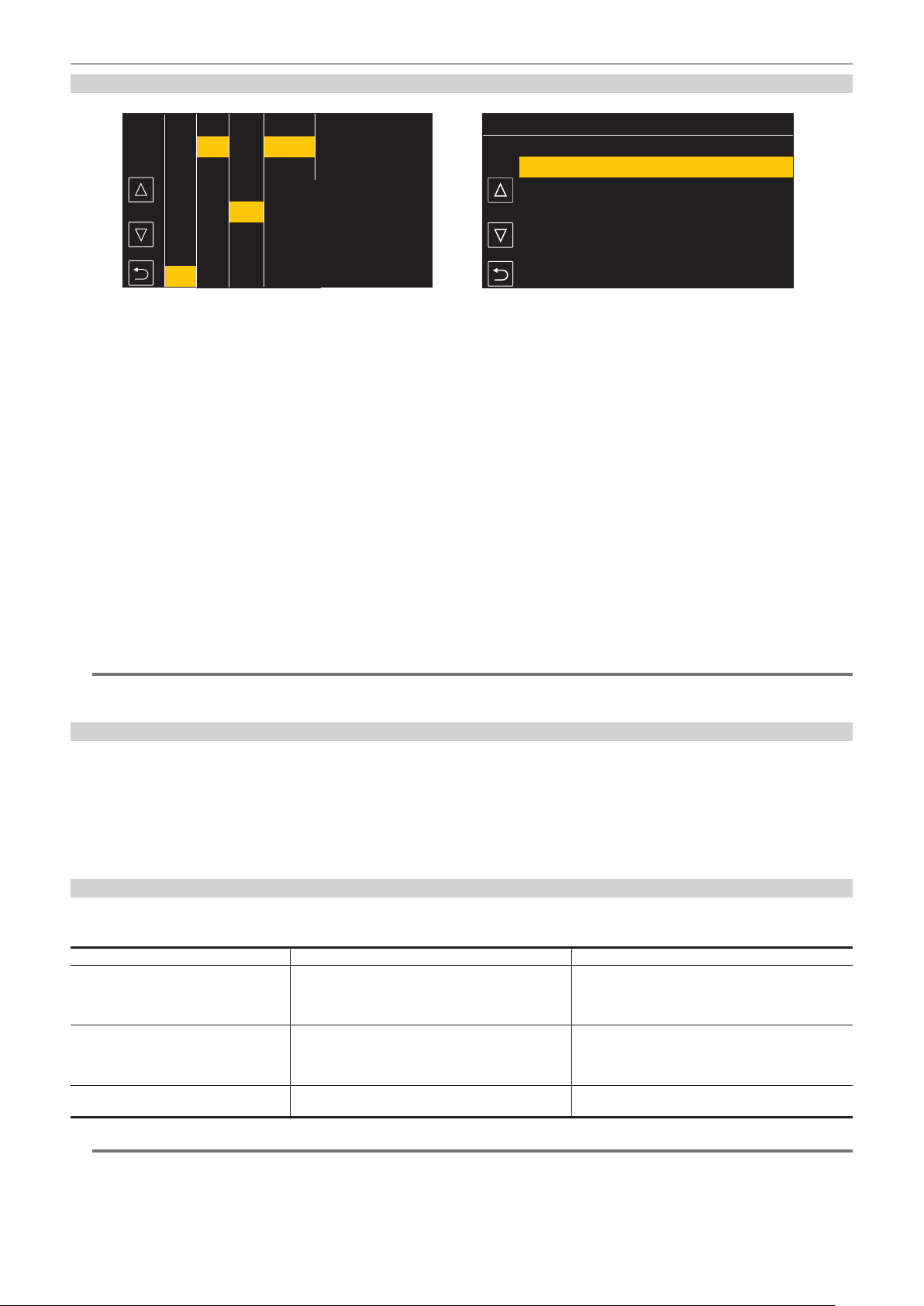
– 41 –
Chapter 3 Preparation — Mounting and adjusting the lens
Loading the chromatic aberration compensation le from the SD card
2/2
1
CJ12ex4.3B IASE S
UA22X8 0BERD-S8
2
Fig. 1 Fig. 2
CAMERA
SCENE FILE
AUDIO
VIDEO OUT/LCD/VF
RECORDING
NETWORK
SYSTEM
OTHERS
EXIT
FILE
BATTERY
GENLOCK
COLOR BARS
LED
CLOCK
GPS
SETUP FILE(SD CARD)
SETUP FILE(MEMORY)
LENS FILE(SD CARD)
LENS FILE(MEMORY)
SLOT FOR LOAD/SAVE
MENU>OTHERS>FILE>CAC FILE(SD CARD)>LOAD
SCENE FILE(SD CARD)
EXIT
CAC FILE(SD CARD)
LOAD
DELETE
EXIT
1
Insert the SD card with the chromatic aberration compensation data that was downloaded from our website into the card slot of
the camera selected by the [OTHERS] menu → [FILE] → [SLOT FOR LOAD/SAVE].
For details on downloading, refer to the following website.
https://pro-av.panasonic.net/
2
Select the [OTHERS] menu → [FILE] → [CAC FILE(SD CARD)] → [LOAD]. (Fig. 1)
The list of CAC les on the SD card is displayed.
3
Select the file number to load. (Fig. 2)
The list of CAC les saved in camera memory is displayed.
4
Select the file number to save.
A conrmation screen is displayed.
5
Select [SET].
The CAC les are loaded to camera memory.
6
To store multiple chromatic aberration compensation data in the camera, repeat steps 2 to 5.
7
Press the <MENU> button to close the menu.
The menu is cleared and returns to the camera status display.
@
NOTE
t Up to 32 les can be loaded to the camera.
To load a new le, delete any le before loading the new le.
Deleting the chromatic aberration compensation le from the camera
1
Set to the [CAMERA] menu → [CAC ADJ.] → [CAC CONTROL] → [OFF].
2
Select the lens model number to delete with [LIST/DELETE].
A conrmation screen is displayed.
3
Select [SET].
The le is deleted.
When the chromatic aberration compensation data is not functioning properly
When the chromatic aberration compensation function is not functioning properly, or when the chromatic aberration compensation data is not loaded
normally, an error message is displayed on the viewnder.
Error message Meaning Remedy
[CAC FILE DATA NOT FOUND] There is no chromatic aberration compensation data
matching the connected lens when the chromatic
aberration compensation function is enabled.
This is displayed when the camera is turned on.
Load chromatic aberration compensation data matching
the connected lens to the camera.
[CAC LENS DATA INVALID] The response data from the lens is not supported, or the
response contains information other than that dened in
the chromatic aberration compensation data.
The lens is not a lens compatible with the chromatic
aberration compensation function.
The chromatic aberration compensation will not function,
but will not cause any problems in use.
[LENS INITIALIZATION NOT
COMPLETED]
Position detection (focus zoom) of the lens is encoder
type, and initialization is not completed.
Turn the focus/zoom ring to pass through the center of
the operating range.
@
NOTE
t When mounting lens optical system accessories (converter lens attachments), the chromatic aberration compensation function sometimes does not
function properly since the optical characteristics of the lens change. In this case, set the chromatic aberration compensation function to [OFF].
t When a focus servo is used on CANON lenses, enable recording after initialization is completed in the automatic initialization mode. Data is
sometimes recording while the focus ring is moving.

– 42 –
Chapter 3 Preparation — Mounting and adjusting the lens
t When an error message is also not displayed while the chromatic aberration compensation function is not functioning, the software version of the lens
might be old. Contact the manufacturer of the lens you are using.
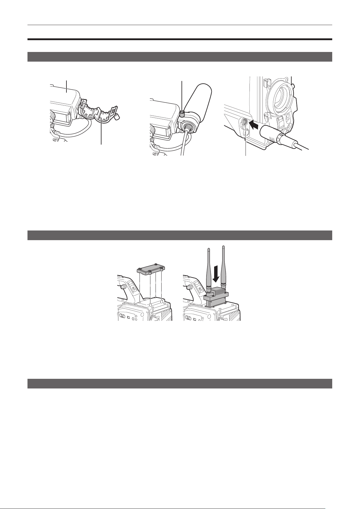
– 43 –
Chapter 3 Preparation — Preparing for audio input
Preparing for audio input
Prepare the camera for connecting audio input devices.
Using the front microphone
Microphones such as the stereo microphone kit AJ-MC900G (optional) can be mounted.
Viewfinder
Microphone holder
<MIC IN> terminal
Viewfinder clamping screw
Fig. 1 Fig. 2 Fig. 3
1
Open the microphone holder. (Fig. 1)
2
Mount the microphone and tighten the viewfinder clamping screw. (Fig. 2)
Mount with the UP indication on the microphone facing up.
3
Connect the microphone cable to the <MIC IN> terminal on the camera. (Fig. 3)
4
Switch the <AUDIO IN CH1> to <AUDIO IN CH4> switches to <FRONT> in accordance to the audio channel to record.
Using the wireless microphone receiver
Fig. 1
1
Remove the cover to insert the wireless microphone receiver and secure it with the screws. (Fig. 1)
2
Switch the <AUDIO IN CH1> to <AUDIO IN CH4> switches to <W.L.> in accordance to the audio channel to record.
3
When using the 2-channel wireless microphone receiver, set to the [AUDIO] menu → [INPUT SETTINGS] → [WIRELESS TYPE] →
[DUAL].
Using audio devices
1
Connect the audio equipment to the <AUDIO IN CH1/3> or <AUDIO IN CH2/4> terminal of the camera with the XLR cable.
2
According to the channel the XLR cable is connected, set the <AUDIO IN CH1> to <AUDIO IN CH4> switches to <REAR>.
3
Set the <LINE>/<MIC> selector switch on the rear panel to <LINE>.
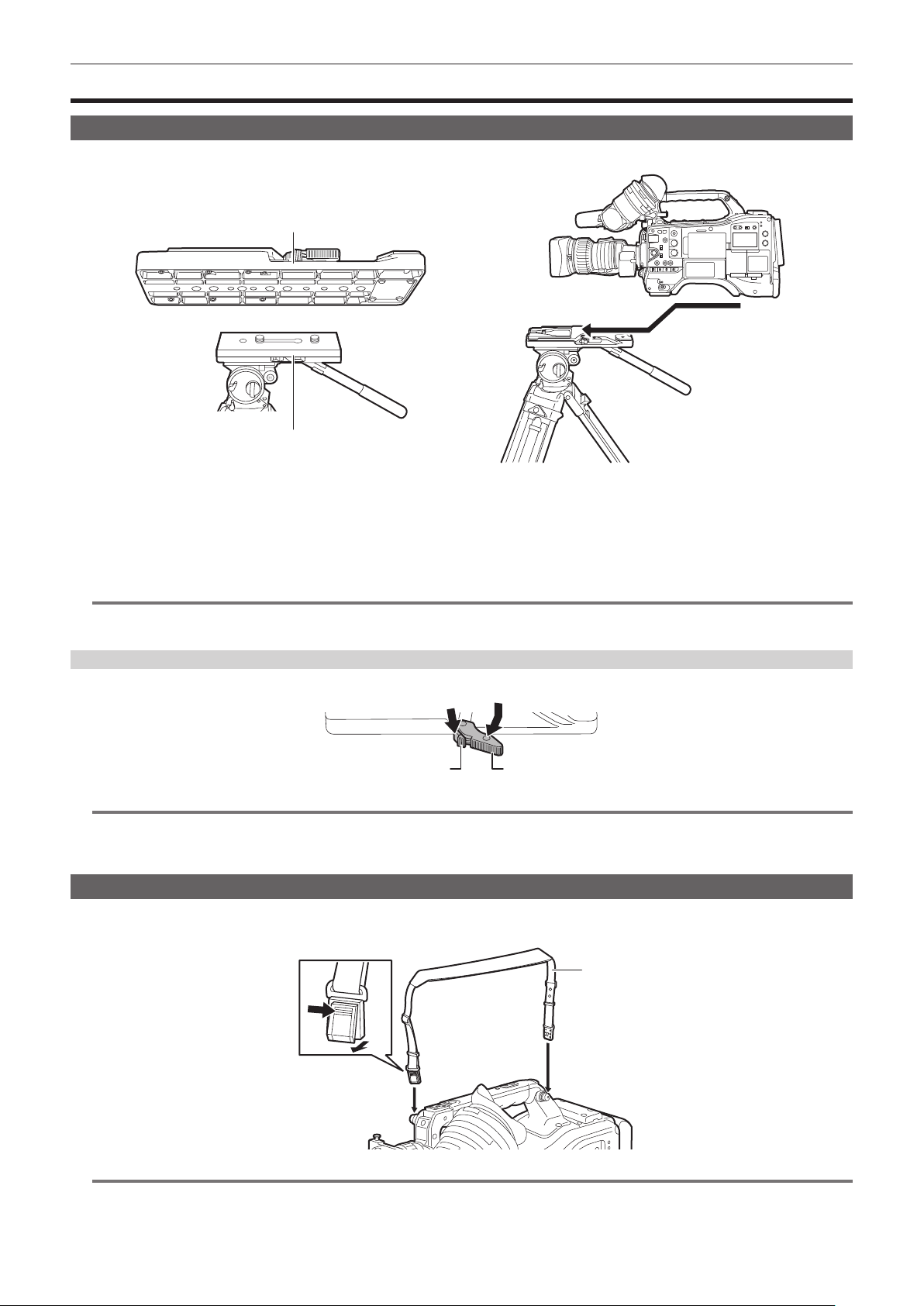
– 44 –
Chapter 3 Preparation — Mounting accessories
Mounting accessories
Mounting the camera on a tripod
When mounting the camera on a tripod, use the optional tripod adaptor (SHAN-TM700).
Fig. 1 Fig. 2
Tripod adaptor
Pan head
1
Mount the tripod adaptor on the tripod. (Fig. 1)
2
Mount the camera on the tripod adaptor. (Fig. 2)
Slide the camera forward along the grooves until you hear a click.
@
NOTE
t Select an appropriate hole in the adaptor, taking into account the center of gravity of the camera and tripod adaptor combined.
Also, make sure that the diameter of the selected hole matches the diameter of the pan head screw.
Removing the camera from the tripod adaptor
While holding the red lever down, move the black lever in the direction of the arrow, and slide the camera backward to remove it.
Red lever Black lever
@
NOTE
t If the tripod adaptor pin does not return to its original position after the camera has been removed, hold the red lever down and move the black lever in
the direction of the arrow again, in order to return the pin to its original position.
Note that the camera cannot be mounted if the pin remains in the center.
Attaching the shoulder strap
Attach the shoulder strap to the shoulder strap ttings.
To detach the shoulder strap, rst open the hooks, then detach the strap.
Shoulder strap
Press to open the hook
@
NOTE
t Make sure that the shoulder strap is securely attached.

– 45 –
Chapter 3 Preparation — Mounting accessories
Attaching the rain cover
The gure below shows an example of use of the rain cover SHAN-RC700 (optional).
Tighten the cord
Secure with the surface
fastener

– 46 –
Chapter 3 Preparation — Charging the built-in battery
Charging the built-in battery
The date/time set in the camera is maintained by the built-in battery.
The built-in battery may be consumed when the power of the camera is not turned on for approximately a half year.
The built-in battery has been consumed if [BACKUP BATT EMPTY] is displayed in the viewnder screen for approximately ve seconds when the power
switch is set to < j > (ON).
Charge the built-in battery with the following procedure.
1
Confirm that the power switch is set to < h > (standby).
2
Connect the battery or the external DC power supply to the camera.
For details on the connection of the battery or the external DC power supply, refer to “Power supply” (page 34).
3
Leave the camera for approximately four hours.
The built-in battery will be charged.
4
Set the power switch to < j > (ON), and confirm that [BACKUP BATT EMPTY] is not displayed in the viewfinder screen.
Replacement of the built-in battery is necessary when [BACKUP BATT EMPTY] is displayed in the viewnder screen even after the built-in battery
has been charged. Consult your dealer.

– 47 –
Chapter 3 Preparation — Setting the date/time of the internal clock
Setting the date/time of the internal clock
The date/time and time zone are recorded as metadata in the content (clip) while shooting. The date/time metadata will affect the playback order by the
thumbnail.
Always check and set the date/time and time zone before using the camera.
Do not change the setting of the date/time and time zone while shooting.
1
Press the <MENU> button.
The menu is displayed.
2
Select the [OTHERS] menu → [CLOCK] → [TIME ZONE] and set the time difference from the Greenwich Mean Time.
3
Select the [OTHERS] menu → [CLOCK] → [CLOCK SETTING] and set the year, month, date, and time.
@
NOTE
t The accuracy of the clock is approximately ±30 seconds per month. Check and reset the time when accurate time is required.
r Time zone table
Time difference Region Time difference Region
00:00 Greenwich
+01:00
Central Europe
−00:30 +01:30
−01:00
Azores
+02:00
Eastern Europe
−01:30 +02:30
−02:00
Mid-Atlantic
+03:00
Moscow
−02:30 +03:30
Tehran
−03:00
Buenos Aires
+04:00
Abu Dhabi
−03:30
Newfoundland
+04:30
Kabul
−04:00
Halifax
+05:00
Islamabad
−04:30
Caracas
+05:30
Mumbai
−05:00
New York
+06:00
Dakar
−05:30 +06:30
Yangon
−06:00
Chicago
+07:00
Bangkok
−06:30 +07:30
−07:00
Denver
+08:00
Beijing
−07:30 +08:30
−08:00
Los Angeles
+09:00
Tokyo
−08:30 +09:30
Darwin
−09:00
Alaska
+10:00
Guam
−09:30
Marquesas Islands
+10:30
Lord Howe Island
−10:00
Hawaii
+11:00
Solomon Islands
−10:30 +11:30
−11:00
Midway Islands
+12:00
New Zealand
−11:30 +12:45
Chatham Islands
−12:00
Kwajalein Atoll
+13:00
Phoenix Islands
+00:30

– 48 –
Chapter 3 Preparation — Inspections before shooting
Inspections before shooting
Before recording, perform the following inspection to ensure that the system operates properly. It is recommended that you check the image using a
color video monitor.
Preparing to inspect
HD
14.6V
FBC1
RELAY
HDR CAC
Fig. 1 Fig. 2
Card access lamp
1
Attach an adequately charged battery.
2
Set the power switch to < j > (ON) and confirm following items.
f [BACKUP BATT EMPTY] is not displayed in the viewnder screen.
f Level of the battery is sufcient in the status display in the control panel. (Fig. 1)
3
From the [RECORDING] menu → [REC MEDIA], select the card slot to record to.
4
Insert the memory card into the card slot.
5
Confirm that the card access lamp of the card slot that the memory card is inserted is illuminated in orange. (Fig. 2)
f When microP2 cards or SD cards are inserted in the card slot 2 and the card slot 3, only the card access lamp of the card slot that was inserted
rst (completed the access rst) will illuminated in orange. The card access lamp of the card slots inserted after will illuminate in green.
f The memory card cannot be recorded when the card access lamp of the card slot that the memory card is inserted is ashing in green or not
illuminated.
f The card access lamp will not illuminate in orange even if a memory card is inserted when the recording format setting does not match with the
inserted memory card.
In such case, match the media of the recording target in the [RECORDING] menu → [REC MEDIA].
6
Close the slot cover.
Inspecting the camera unit
1
Set the zoom to the electric zoom mode and check the behavior of the electric zoom.
Ensure that the image changes between telescopic and wide-angle.
2
Set the zoom to the manual zoom mode and check the behavior of the manual zoom.
Rotate the manual zoom lever and ensure that the image changes between telescopic and wide-angle.
3
Set the iris to automatic adjustment mode, and ensure that the automatic adjustment works when the lens is pointed at objects
with different degree of brightness.
4
Set the iris to manual mode and rotate the iris ring to check the manual iris adjustment.
5
Set the iris back to automatic adjustment mode, and check the followings by switching the <GAIN> switch setting to <L>, <M>,
and then <H>:
f The iris is adjusted for objects with same degree of brightness as the setting changes.
f The gain value display on the viewnder screen changes as the setting changes.
6
If a lens with an extender function is attached, set the extender to its usage position to ensure that it works properly.
Inspecting the memory recording functions
Perform procedures from “Inspecting the memory card recording” to “Inspecting the earphones and built-in speaker” successively.
Inspecting the memory card recording
1
Confirm that the remaining memory card capacity is sufficient with the display in the viewfinder screen.
For details, refer to “Screen display during shooting” (page 154).
2
Press the <REC> button and check the following:
f The card access lamp of the card slot the memory card is inserted ashes in orange.
f The [REC] lamp in the viewnder illuminates.

– 49 –
Chapter 3 Preparation — Inspections before shooting
f Warning is not displayed in the viewnder screen.
3
Press the <REC> button again.
Conrm that the card access lamp illuminates in orange and the [REC] lamp inside the viewnder turns off.
4
Use the <VTR> button on the lens and confirm the same operation as steps 2 to 3.
5
Press the <BRIGHT> button to confirm that the display brightness of the display window is switched.
6
Press the <THUMBNAIL> button to switch to the thumbnail screen, and from the thumbnail, play back the clip you just recorded.
Ensure that the clip plays back properly.
7
When two microP2 cards or SD cards are inserted in the card slots, switch the target card slot by pressing the USER button
assigned with [SLOT SEL].
Perform steps 2 to 3 and step 6 and conrm that the recording and playback functions operate properly.
Inspecting the recording level automatic adjustment function
1
Set the <AUDIO SELECT CH1/3>/<AUDIO SELECT CH2/4> switch to <AUTO>.
2
Set the <AUDIO IN CH1>/<AUDIO IN CH2> or <AUDIO IN CH3>/<AUDIO IN CH4> switch to <FRONT>.
3
Point the microphone connected to the <MIC IN> terminal to an appropriate audio source, and confirm that the audio level meter
changes in accordance with the intensity of the sound.
Inspecting the recording level manual adjustment function
1
Set the <AUDIO IN CH1>/<AUDIO IN CH2> or <AUDIO IN CH3>/<AUDIO IN CH4> switch to <FRONT>.
2
Set the <AUDIO SELECT CH1/3>/<AUDIO SELECT CH2/4> switch to <MANU>.
3
Turn the <AUDIO LEVEL CH1/3>/<AUDIO LEVEL CH2/4> dial.
Turn to the right to increase the level display.
Inspecting the earphones and built-in speaker
1
Turn the <MONITOR> dial and confirm that the built-in speaker volume changes.
2
Connect earphones to the <PHONES> terminal.
Conrm that the built-in speaker is muted and the output from the microphone is directed to the earphones.
3
Turn the <MONITOR> dial and ensure that the earphones volume changes.
Inspections for using an external microphone
1
Connect the external microphone to the <AUDIO IN CH1/3> terminal or <AUDIO IN CH2/4> terminal.
2
Set the <AUDIO IN CH1>/<AUDIO IN CH2> switch to <REAR>.
3
Toggle the microphone input power selector switch according to the power supply method for the external microphone.
f Selection items
- <+48V>: Microphone with an external power supply method
- <OFF>: Microphone with an internal power supply method
4
Point the microphone to an appropriate audio source, and confirm that the audio level meter changes in accordance with the
intensity of the sound.
It can also be conrmed for each audio channel by connecting one microphone to each audio channel.
Inspections for the clock, time code, and user bits
1
Set the user bits as needed.
For details, refer to “Setting user bits” (page 150).
2
Set the time code.
For details, refer to “Setting time code” (page 151).
3
Set the <TCG> switch to <R-RUN>.
4
Press the <REC> button.
Ensure that the recording starts and the number in the counter display changes.
5
Press the <REC> button again.
Ensure that the recording stops and the number in the counter display stops changing.

– 50 –
Chapter 3 Preparation — Inspections before shooting
6
Set the <TCG> switch to <F-RUN>.
Ensure that the number in the counter display changes regardless of the recording status.
7
Set the <DISPLAY> switch to <UB>.
Ensure that the user bits displayed in the counter display area is correct.
8
Ensure that the time zone, date, and time are correct by selecting the [OTHERS] menu → [CLOCK] → [TIME ZONE]/[CLOCK
SETTING].
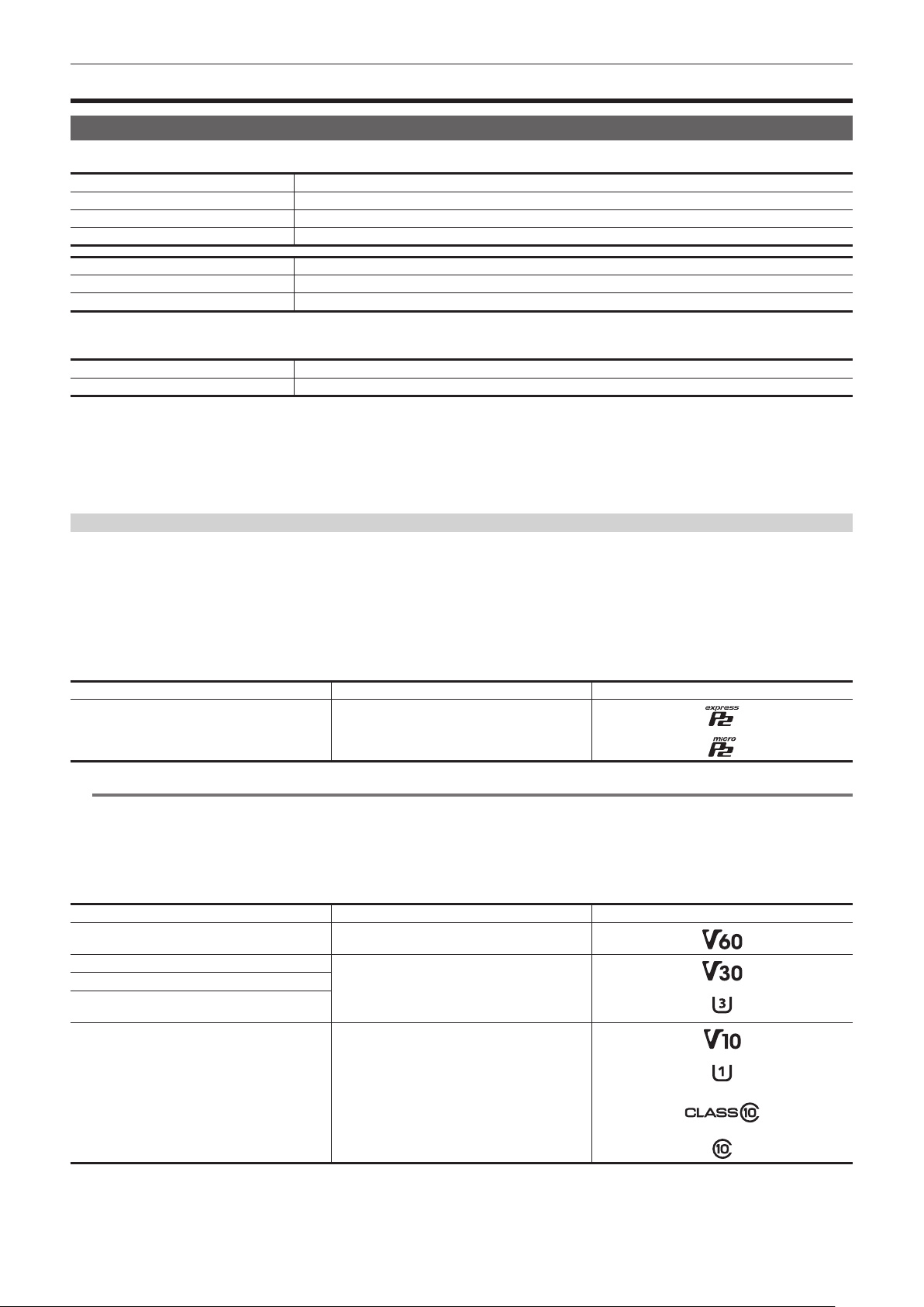
– 51 –
Chapter 3 Preparation — Preparing the memory card
Preparing the memory card
Memory cards supported on the camera
Following expressP2 card, microP2 card, and SD card can be used with the camera. (As of March 2021)
Type of the expressP2 card Recording capacity
expressP2 card A series 256 GB
expressP2 card B series 256 GB, 512 GB
expressP2 card C series 256 GB, 512 GB
Type of the microP2 card Recording capacity
microP2 card A series 32 GB, 64 GB
microP2 card B series 64 GB
f The camera does not support the CPS (Content Protection System) function of the P2 card, so a P2 card formatted with encryption with CPS
password cannot be sued. When formatted with the camera, it can be used as a P2 card that is not encrypted.
Type of the SD card Recording capacity
SDXC memory card 48 GB - 256 GB
f The following memory cards cannot be used because they do not comply with the SD standards.
-A memory card with 48 GB or more without the SDXC logo
f Operation of all the above mentioned memory cards are not always assured.
f Following memory cards cannot be used.
-P2 memory card
-microP2 card with microP2 card adaptor attached
Speed Class during shooting
The type of the memory card to use differs depending on the recording mode and the recording format.
Use memory cards compatible with the Speed Class, UHS Speed Class, or Video Speed Class.
The recording may stop suddenly when a memory card not compatible with the required Speed Class is used.
f Speed Class, UHS Speed Class, and Video Speed Class are the speed specication regarding continuous writing. Check the display on the label and
other information on the memory card.
r When the recording mode is P2
expressP2 card, microP2 card, and SDXC memory card can be used.
Recording bit rate or recording function Type of memory card Example of the logo display
Memory card types supported on the camera
expressP2 card, microP2 card, SDXC memory card
(Card that the operation is conrmed by Panasonic
is recommended)
@
NOTE
t For details on the SD card that the operation is conrmed, visit the support desk at the following website:
https://pro-av.panasonic.net/
r When the recording mode is MOV
expressP2 card, 64 GB microP2 card, and SDXC card can be used.
SDHC card, 32 GB microP2 card cannot be used.
Recording bit rate or recording function Type of memory card and Speed Class Example of the logo display
400 Mbps
Video Speed Class V60 or higher
Or the expressP2 card, microP2 card B series
200 Mbps
Video Speed Class V30 or higher, UHS Speed
Class 3 or higher
Or the expressP2 card, microP2 card
150 Mbps
100 Mbps
50 Mbps
Video Speed Class V10 or higher, UHS Speed
Class 1 or higher, Speed Class 10 or higher
Or the expressP2 card, microP2 card
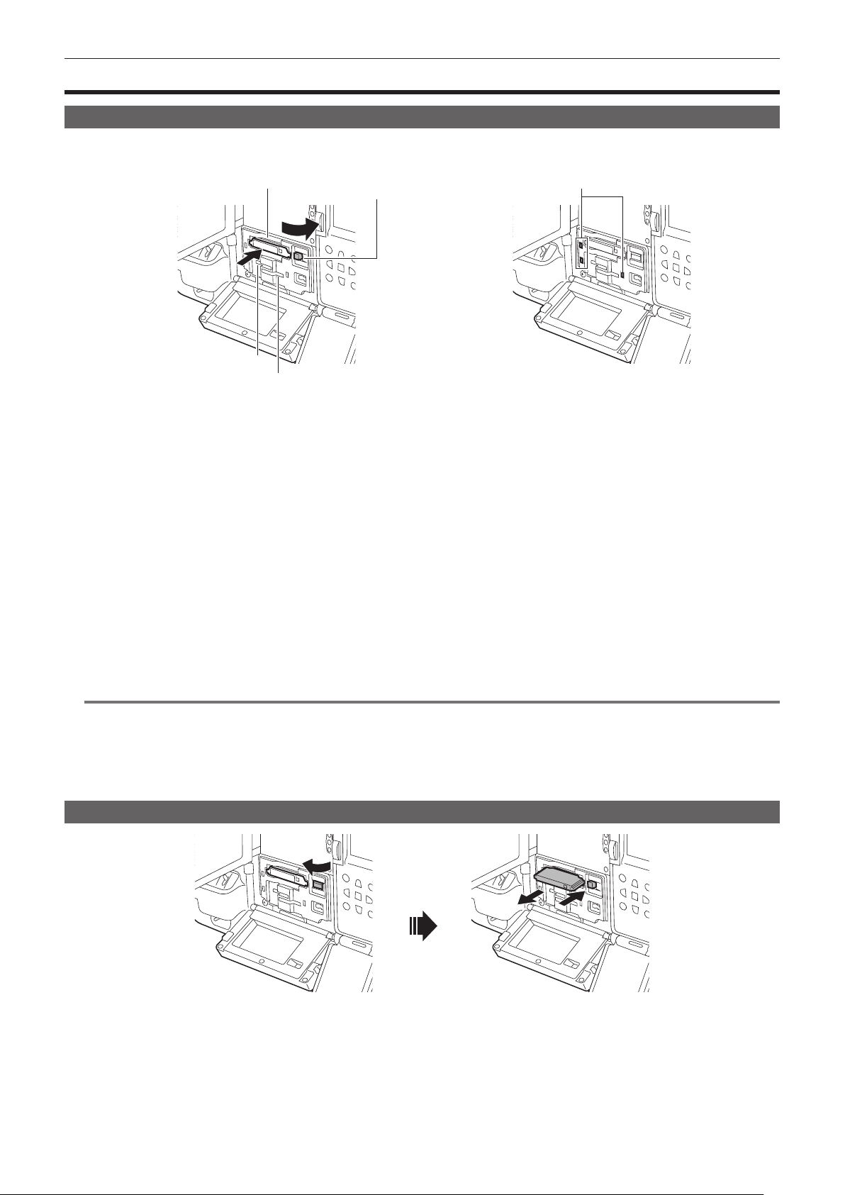
– 52 –
Chapter 3 Preparation — Memory cards
Memory cards
Inserting the memory card
When using the camera for the rst time, be sure to set the time data beforehand. (page 47)
This camera uses the card slot 1 dedicated for a expressP2 card, and the card slot 2/3 for a microP2 card or a SD card.
Card access lamp
Eject button
Card slot 1
Card slot 2
Card slot 3
Fig. 1 Fig. 2
1
Set the power switch to < j > (ON).
2
Set which of expressP2 card or microP2 card to be used.
Select in the [RECORDING] menu → [REC MEDIA] → [expressP2]/[microP2/SD].
3
Open the slot cover.
4
Insert the memory card into the card slot. (Fig. 1)
f For expressP2 card
- Insert with the logo facing up.
- Push in the expressP2 card until the eject button pops out.
- Press the eject button that pops up to the right.
f For microP2 card or SD card
- Insert with the label side facing up.
f The status of the memory card is displayed with the card access lamp of the inserted card slot. (Fig. 2) (page 53)
5
Close the slot cover.
@
NOTE
t To prevent cards from falling out, dust from entering and reduce the risk of exposure to static electricity, close the slot cover before moving the camera.
t Be sure to format P2 cards only on a P2 device.
t microP2 card with microP2 card adaptor attached cannot be used.
t It may display [FORMAT ERROR CARD <SLOT 2>] or [REINSERT OR CHECK CARD <SLOT 2>] (corresponding card slot number is displayed)
when a memory card is inserted slowly into the card slot 2 or the card slot 3, or when the terminal of the memory card is dirty. In such case, reinsert
the memory card.
Removing the memory card
Fig. 1 Fig. 2
1
Open the slot cover.
2
Remove the memory card.
f For expressP2 card
- Lift the eject button (Fig. 1), and press in. (Fig. 2)
- Remove the expressP2 card when it comes out from the slot.
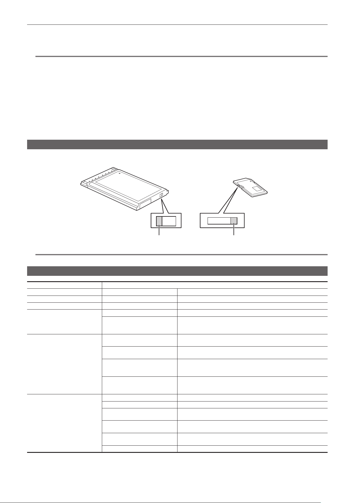
– 53 –
Chapter 3 Preparation — Memory cards
f For microP2 card or SD card
- Press in the microP2 card or SD card further inside and let go.
- Remove the microP2 card or SD card when it comes out from the slot.
@
NOTE
t Do not remove the memory card while it is being accessed or while the card access lamp is ashing in orange after it is inserted. Doing so may result
in a malfunction.
t Turn off the power once when the memory card being accessed is removed.
t The clips may become invalid on the memory card that was removed while being accessed. Check the clips and restore them, if required. (page 185)
t The format of the removed memory card cannot be guaranteed when the memory card being formatted is removed. Turn off the power then back on
again, and reformat the memory card.
t If a memory card is inserted into another card slot during playback, the inserted card is not recognized and the card access lamp does not illuminate.
Recognition of the memory card will start after the playback ends.
t In following conditions, the memory card is not immediately recognized even if a memory card is inserted into a vacant card slot during recording:
- Immediately after a pre-recording
- Immediately after switching the recording target card slot
t The card access lamp can be set to off at all time by the [OTHERS] menu → [LED] → [ACCESS LED]. In such case, remove the memory card after
turning off the power or after inserting the card or the operation (recording, playback, etc.) has stopped and sufcient time has passed.
Preventing accidental erasure
To prevent inadvertently erase the recording contents on the memory card, set the write-protected switch on the memory card to the Protect side or the
LOCK side.
Write-protected switch Write-protected switch
@
NOTE
t Set the write-protected switch before inserting the card. This will not operated when the write-protected switch is toggled after inserting the card.
Status of the card access lamp and the memory card
Card access lamp Memory card status
Is illuminated green Recording possible Both loading/writing are permitted.
Is illuminated orange Recording target Both loading/writing are permitted. Current recording target.
Flashing orange Accessing card Loading/writing are currently being performed.
Flashing orange rapidly
Recognizing memory card The memory card is being recognized.
Error
An error has occurred.
This will ash even if the memory card is not inserted when an error has
occurred.
Flashing green slowly
No remaining memory card capacity
Memory card has no remaining capacity.
Only loading is possible.
Write-protected
The write-protected switch on the memory card is set to the Protect side or the
LOCK side. Only loading is possible.
Unrecordable memory card
It cannot record with the recording format that is currently set.
Change the recording format or use a memory card compatible with the
recording format.
Card slot that is not recording target
A memory card is inserted into the card slot not selected in the [RECORDING]
menu → [REC MEDIA].
Only loading is possible.
Off
Illegal format The memory card is not properly formatted. Reformat the card.
No memory card inserted A memory card has not been inserted.
Invalid memory card
This is a memory card such as MMC (Multi Media Card) that cannot be used
with the camera.
Setting to the [NETWORK] menu →
[NETWORK FUNC] → [NDI|HX]
Cannot record and play back. The functions other than recording and playback
(loading of the scene le, etc.) can be used.
P2 card formatted with encryption with
CPS password
Cannot be used with the camera. When formatted with the camera, it can be
used as a P2 card that is not encrypted.
During card reader mode The card access lamp is turned off unless accessing.
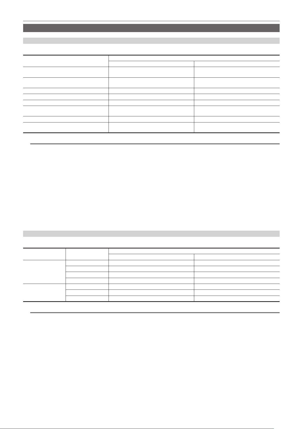
– 54 –
Chapter 3 Preparation — Memory cards
Memory card recording time
When the recording mode is P2
expressP2 card, SDHC memory card, SDXC memory card, and microP2 card can be used.
Recording format
Recording capacity
64 GB 64 GB (during proxy recording)
AVC-Intra 422/AVC-Intra 200/AVC-Intra 100
(1080-59.94p/50.00p)
Approx. 32 minutes Approx. 30 minutes
AVC-Intra 100 (1080-59.94i/50.00i,
720-59.94p/50.00p)
Approx. 64 minutes Approx. 60 minutes
AVC-Intra 50 Approx. 128 minutes Approx. 114 minutes
AVC-LongG50 Approx. 128 minutes Approx. 114 minutes
AVC-LongG25 (1080-59.94p/50.00p) Approx. 128 minutes Approx. 114 minutes
AVC-LongG25 (1080-59.94i/50.00i,
720-59.94p/50.00p)
Approx. 256 minutes Approx. 206 minutes
AVC-LongG12 (1080-59.94p/50.00p) Approx. 240 minutes —
AVC-LongG12 (1080-59.94i/50.00i,
720-59.94p/50.00p)
Approx. 480 minutes —
@
NOTE
t For details on the SD card that the operation is conrmed, visit the support desk at the following website:
https://pro-av.panasonic.net/
t The clip in P2 format data is split every 4 GB when [SPLIT] is selected in the [RECORDING] menu → [FILE SPLIT].
Also, it is split approximately every 128 seconds if [SHORT SPLIT] is selected in the [RECORDING] menu → [FILE SPLIT].
However, when recording to a memory card exceeding 32 GB in AVC-Intra 422/AVC-LongG50/AVC-LongG25/AVC-LongG12 formats, recording can
be continued as a same clip by selecting the [RECORDING] menu → [FILE SPLIT] → [ONE FILE]. Clip is split approximately every three hours when
recording format is AVC-Intra 422. Clip is split approximately every three hours or approximately every 64 GB when recording format is AVC-LongG50/
AVC-LongG25/AVC-LongG12.
These split clips are displayed as one clip in the thumbnail screen.
These may be displayed as separate clips in the nonlinear editing software or a computer.
t The recording is stopped once when the recording time reaches ten hours, and recording is automatically resumed after few seconds. Image and
audio during the pause will not be recorded. This includes the case of special recording, such as relay recording.
t In the interval recording, the recording is stopped once when the length of a clip reaches ten hours, and recording is automatically resumed after few
seconds.
t The camera does not support the CPS (Content Protection System) function of the P2 card, so a P2 card formatted with encryption with CPS
password cannot be used. When formatted with the camera, it can be used as a P2 card that is not encrypted.
When the recording mode is MOV
expressP2 card, 64 GB microP2 card, and SDXC card can be used. 32 GB microP2 card cannot be used.
Recording format Recording rate
Recording capacity
64 GB 128 GB
UHD
400 Mbps Approx. 20 minutes Approx. 40 minutes
200 Mbps Approx. 40 minutes Approx. 1 hour 20 minutes
150 Mbps Approx. 55 minutes Approx. 1 hour 50 minutes
100 Mbps Approx. 1 hour 20 minutes Approx. 2 hours 40 minutes
FHD
200 Mbps Approx. 40 minutes Approx. 1 hour 20 minutes
100 Mbps Approx. 1 hour 20 minutes Approx. 2 hours 40 minutes
50 Mbps Approx. 2 hours 40 minutes Approx. 5 hours 20 minutes
@
NOTE
t File is split approximately every three hours for the data in MOV format.
These are displayed as separate clips in the thumbnail screen. In addition, the clips recorded across two memory cards using the relay recording are
displayed as separate clips.
t The recording is stopped once when the recording time reaches ten hours, and recording is automatically resumed after few seconds. Image and
audio during the pause will not be recorded. This includes the case of special recording, such as relay recording.
t In the interval recording, the recording is stopped once when the length of a clip reaches ten hours, and recording is automatically resumed after few
seconds.
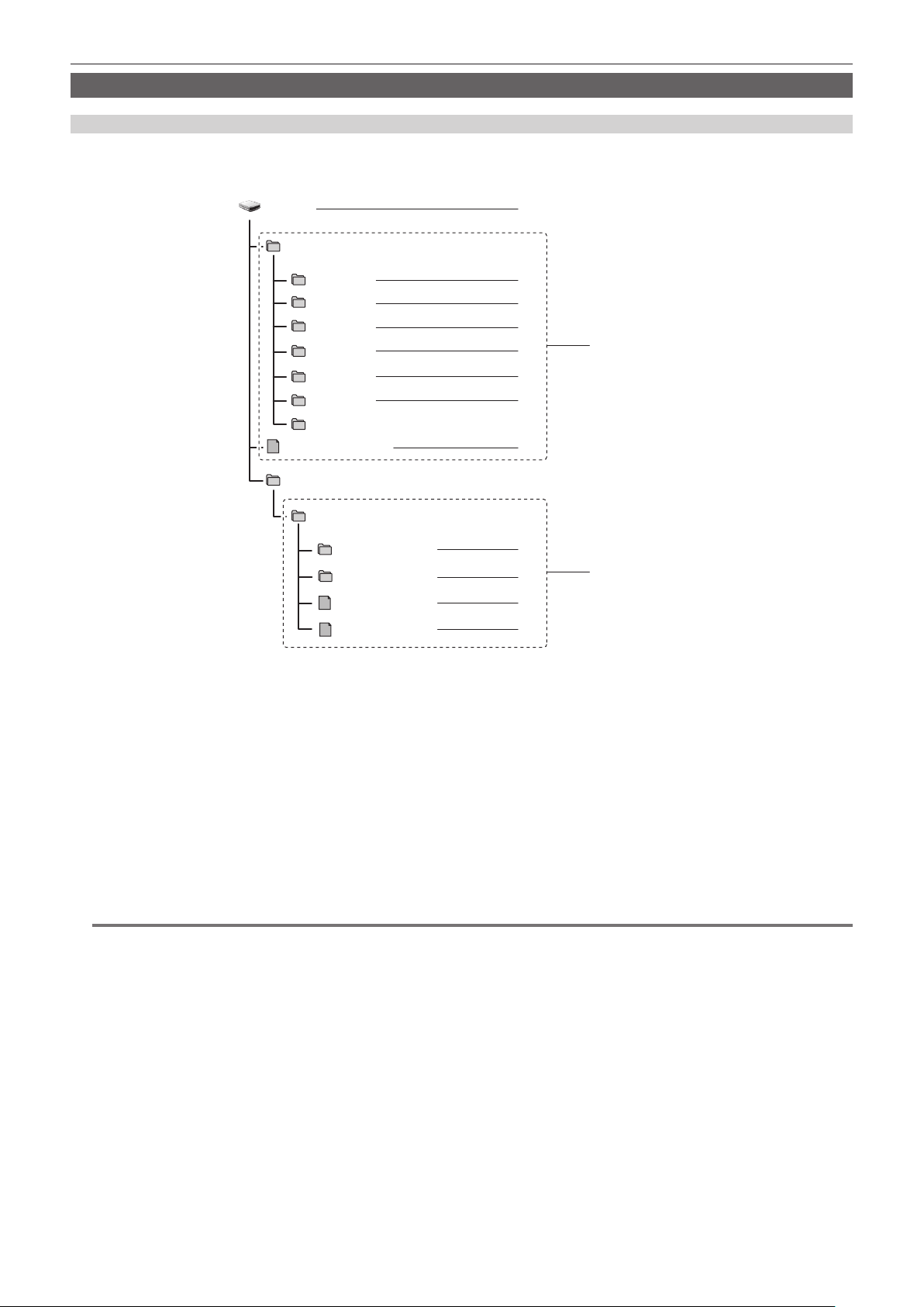
– 55 –
Chapter 3 Preparation — Memory cards
Handling recording data
Folder structure example of a memory card
Various important information is contained in the recording data, and has a folder structure as shown in the gure and linked by the management les.
If the information is changed or deleted even partially, an error such as that the data cannot be recognized or the recording becomes impossible may
occur.
B002
PRIVATE
CONTENTS
LASTCLIP.TXT
AVCLIP
AUDIO
CLIP
PANA_GRP
001RCQAM
002YCJAM
BACKUP.TMP
INDEX.DAT
1
9
10
11
12
2
4
3
8
ICON
5
7
6
PROXY
VIDEO
VOICE
P2 format
MOV format
1 Volume label of the memory card
2 Video data in MXF format (audio: LPCM) (when recording format is AVC-Intra 422/AVC-LongG50/AVC-LongG25/AVC-LongG12)
3 Audio data in MXF format (when recording format is AVC-Intra 200/AVC-Intra 100/AVC-Intra 50)
4 Meta data in XML format
5 Thumbnail in BMP format
6 Proxy data in MOV format and realtime metadata in BIN format
7 Video data in MXF format (when recording format is AVC-Intra 200/AVC-Intra 100/AVC-Intra 50)
8 The le to which the information of the nal clip was recorded
9 Video data in MOV format: UHD (3840×2160), 29.97p MOV (audio: LPCM)
10 Video data in MOV format: FHD (1920×1080), 59.94i MOV (audio: LPCM)
11 Management le 1
12 Management le 2
@
NOTE
t Do not erase a folder or le on the memory card with a computer. It may make it impossible to load on the camera.
t If data is recorded to the memory card with a computer, an error may occur such as an inability to recognize or record to the memory card with the
camera.
t The memory card to use with the camera should always be formatted on the camera.
t The number of the P2 format clips that can be recorded on a single memory card is approximately 1000.
Data will not be able to record when it reaches the maximum number of data that can be recorded.
t When transferring a recording data in a P2 format to a computer, or when writing back to a microP2 card, be sure to use the dedicated software “P2
Viewer Plus” to prevent data loss. For details on downloading P2 Viewer Plus and the operating environment, visit the support desk at the following
website:
https://pro-av.panasonic.net/
t Follow the instructions below when using a general IT tool such as the OS standard le manager equipped on a computer to transfer a recording data
in P2 format to a computer. However, be sure to use P2 Viewer Plus when returning data back to a microP2 card.
- Perform the transfer for each CONTENTS folder and LASTCLIP.TXT le.
- Do not operate the folders under the CONTENTS folder.
- When copying, copy the LASTCLIP.TXT le at the same time as the CONTENTS folder.
- When transferring the data in multiple microP2 cards to a computer, create a folder for each memory card to prevent clips with the same name from
being overwritten.
- Do not delete data inside a memory card.
- Be sure to format the memory card with a P2 device or P2 Viewer Plus.

– 56 –
Chapter 3 Preparation — Memory cards
Volume label of the memory card
r When the recording mode is P2
The card serial number is stored in the volume label if the memory card being used is the microP2 card. “CAM_SD” is stored in the volume label if a
card other than the microP2 card is used.
r When the recording mode is MOV
The value set in the [RECORDING] menu → [CLIP NAME] is stored in the volume label in the CAM INDEX + NEXT CARD COUNT format when the
memory card is formatted. Once it is stored, [NEXT CARD COUNT] will increase by one. The CARD COUNT that is stored is also used for the CARD
number of the MOV format le name.
@
NOTE
t When recording to the memory card that CAM INDEX + CARD COUNT is not stored in the volume label, the value set in the [RECORDING] menu →
[CLIP NAME] is automatically stored in the volume label, and [NEXT CARD COUNT] will increase by one.
Folder name of the MOV format video data
The fourth through eighth characters of the folder name differ depending on the setting of the camera.
0 0 1 R A Q A M
1 2 3 4 5 6
7
1 Folder number
001 to 999 (sequential number)
f The number of clips that can be recorded in one folder is 999. Once it reaches 999, a folder with sequential number added is newly created.
Also, a folder with sequential number added is newly created when the folder name is changed by changing the setting of the camera.
The folder name will return to 001 when the memory card is formatted.
2 Number of pixels
R: 3840×2160
Y: 1920×1080
3 Frame rate
A: 59.94fps
B: 50.00fps
C: 29.97fps
D: 25.00fps
F: 23.98fps
4 Video format
Q: Progressive recording (MOV, LPCM)
J: Interlace recording (MOV, LPCM)
5 Fixed values
A
6 Recording setting
M: Standard recording
f Added to the le name recorded in card slot 2 for the simultaneous recording.
T: Simultaneous recording
f Added to the le name recorded in card slot 3 for the simultaneous recording.
7 Recording format information
r When the folder name is 001RAQAM
Following video data is saved in the folder.
f Number of pixels: 3840×2160
f Frame rate: 59.94fps
f Video format: Progressive recording (MOV, LPCM)
File name of the MOV format video data
The format of the le name is as follows.
B 0 0 2 C 0 1 0 _ 1 9 0 9 1 8 _ E 1 2 5
.MOV
21 3 4 5
1 CAM INDEX
One character from upper case A to Z.
f An INDEX assigned to each camera. Set with the [RECORDING] menu → [CLIP NAME] → [CAM INDEX].
2 CARD number
001 - 999
f This is the number assigned to each memory card. The CARD COUNT stored in the volume label of the memory card can be assigned.

– 57 –
Chapter 3 Preparation — Memory cards
3 Clip number
C001 - C999
f This is a sequential number assigned to each recording on the memory card. The number returns to C001 when the memory card is formatted. It
will also return to C001 for the one after C999.
The clip number is maintained even when the folder is split or when the clip is deleted.
4 Date
Last two digits of year + two digits of month + two digits of date when the recording is started.
5 Hashtag generated from the serial number
Four-digit number or alphabet
@
NOTE
t The clip name of the card slot 3 will be the same as the clip name of the card slot 2 for the simultaneous recording.
t The maximum number of folder and the folder number is 999. The recording is prohibited when it reaches 999 even if number in between is open.
t The number of clips that can be recorded on a single memory card is approximately 4000. Data will not be able to be recorded when it reaches the
maximum number of clips that can be recorded even if number in between is open.

This chapter describes how to operate the screen of this camera, how to operate the menu, the structure of the menu, and details of the menu.
Chapter 4 Operation
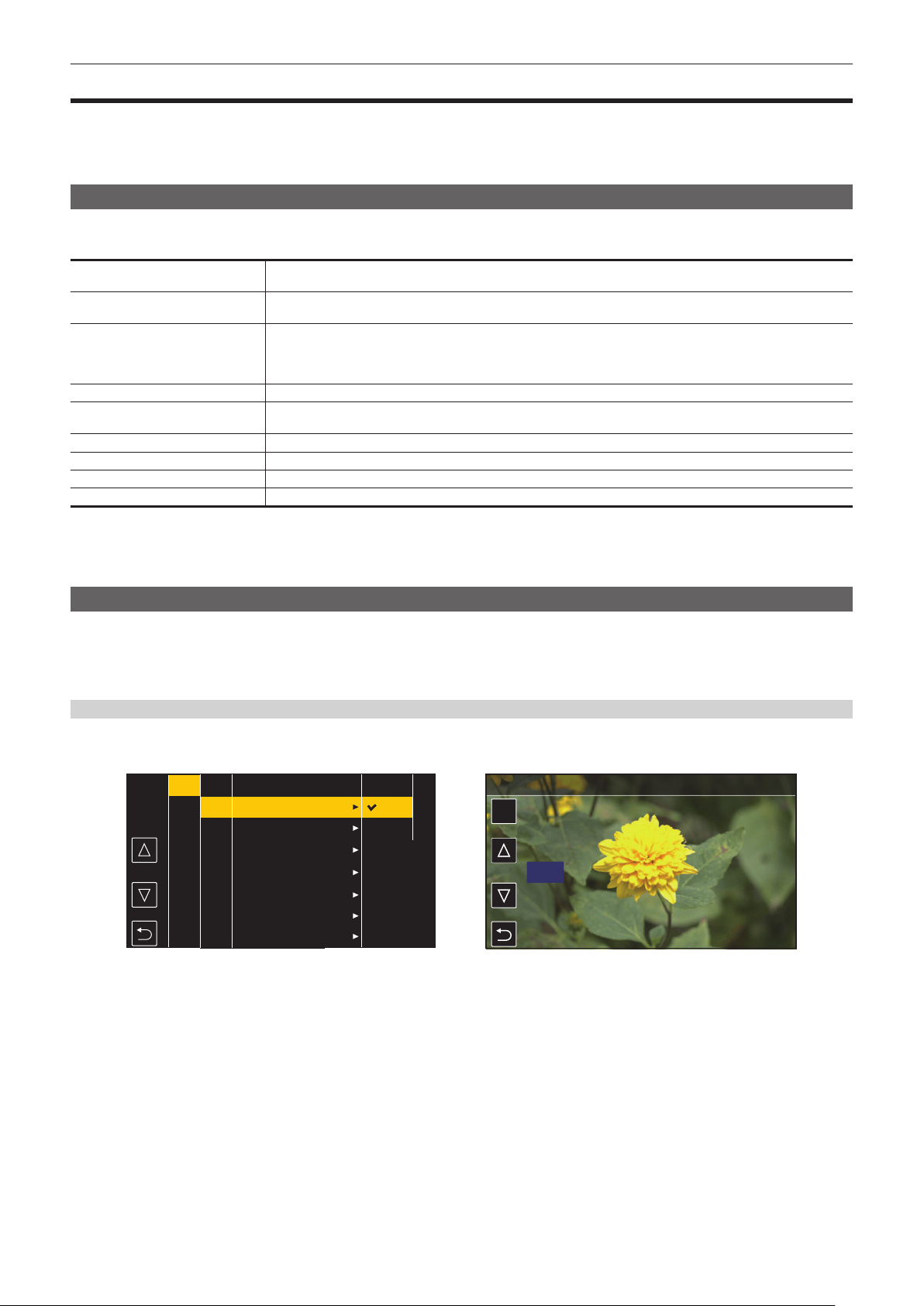
– 59 –
Chapter 4 Operation — Basic operation of the menu
Basic operation of the menu
The setting of the camera can be changed with the menu in accordance to the shooting scene or recording contents.
Set data is written and saved in the camera memory.
f There are two methods of operation, a method to operate with the jog dial button or the cursor operation button, and a method to touch the LCD
monitor.
Conguration of the menu
The menu is structured in categorized levels according to intended use and setting frequency.
Displayed by pressing the <MENU> button.
[THUMBNAIL] menu Performs conrmation or deleting of the recording clip.
Can be set when the thumbnail screen is displayed.
[CAMERA] menu Sets the basic function of the camera.
Cannot be set when the thumbnail screen is displayed.
[SCENE FILE] menu Sets the setting regarding scene le.
Sets the detailed image quality adjustment of the camera video. Also, selection of the scene le, writing the scene le
data to the camera memory, and loading from the camera memory can be performed.
Cannot be set when the thumbnail screen is displayed.
[AUDIO] menu Sets the input/output function of audio.
[VIDEO OUT/LCD/VF] menu Congures the settings for the external output, the information to display in the LCD monitor or viewnder and the output
format.
[RECORDING] menu Sets the various items in the recording function.
[NETWORK] menu Sets the setting regarding the network function.
[SYSTEM] menu Congures the settings regarding the recording format of video and audio.
[OTHERS] menu Congures the settings for writing/loading/initializing of the user le into the camera memory and other settings.
r [OPTION] menu
A special menu is prepared considering additional functions in the future.
This is displayed by pressing the <MENU> button while holding down the <SHIFT> button.
Basic operation of the menu
The setting of the camera can be changed with the menu in accordance to the shooting scene or recording contents.
Set data is written and saved in the camera memory.
Various settings are possible from the menu.
There are two methods of operation, a method to operate with the jog dial button or the cursor operation button, and a method to touch the LCD monitor.
When operating with the button
Operate by turning or pressing the jog dial button on the camera.
It can also be operated by pressing the cursor operation button and the <SET> button.
SET
50
Fig. 1 Fig. 2
CAMERA
SCENE FILE
AUDIO
VIDEO OUT/LCD/VF
RECORDING
NETWORK
SYSTEM
OTHERS
EXIT
SHUTTER SPEED
SW MODE
USER SW
WHITE BALANCE MODE
USER SW GAIN
LENS/IRIS
LENS ADJ.
POSITION1
POSITION2
POSITION3
POSITION4
POSITION5
POSITION6
ON
OFF
EXIT
MENU>CAMERA>LENS/IRIS>A.IRIS LEVEL
SYNCHRO SCAN
EXIT
ON
1/100
1/120
1/250
1/500
1/1000
1/2000
1
Press the <MENU> button when not recording.
The menu is displayed.
2
Select the menu to set.
1) Turn the jog dial button to move the cursor to the item to set.
The cursor can also be moved by pressing the cursor operation button.
2) Press the jog dial button or the <SET> button.
The lower level menu is displayed.
f The conrmation screen is displayed depending on the menu.
f Perform the similar operation if there is next level.
f In some menus, a screen to set the numeric value is displayed in the camera image. (Fig. 2)
f In some menus, a message is displayed if a menu cannot be executed.
f To return to one level higher, perform the following operation.
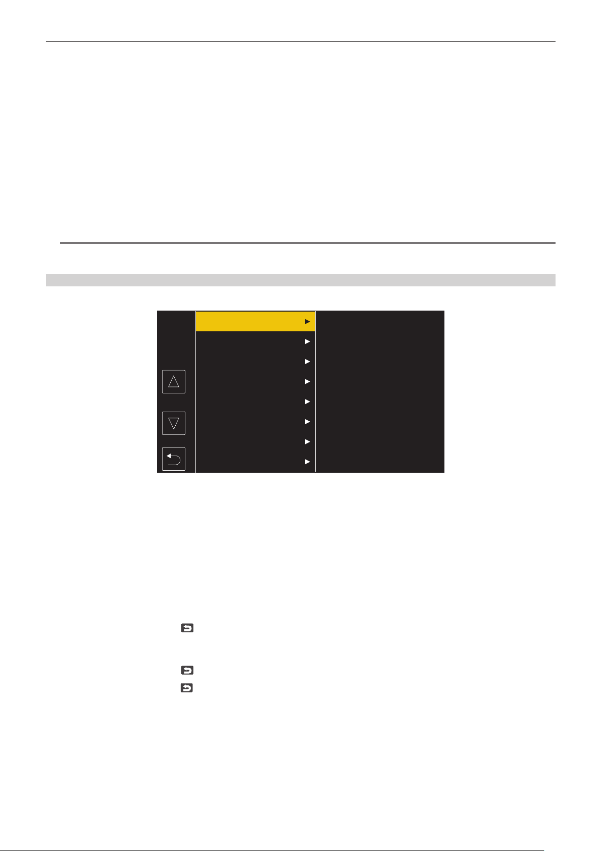
– 60 –
Chapter 4 Operation — Basic operation of the menu
- Press the <EXIT> button.
- Press the cursor operation button.
- Place the cursor on [EXIT] at the top and press the <SET> button or the jog dial button.
3
Select the item to set.
1) Turn the jog dial button to move the cursor to the item to set.
The cursor can also be moved by pressing the cursor operation button.
2) Press the jog dial button or the <SET> button.
A check mark is displayed at the left of the set item. (Fig. 1)
f To return to one level higher, perform the following operation.
- Press the <EXIT> button.
- Press the cursor operation button.
- Place the cursor on [EXIT] at the top and press the <SET> button or the jog dial button.
4
Press the <MENU> button to close the menu.
f Depending on the operating item, it will automatically return to the previous screen.
@
NOTE
t In the screen to set the numeric value (Fig. 2), the value is changed fast by turning the jog dial button in the direction to change with the button
pressed and xing it or press and hold the cursor operation button.
When operating by touching the LCD monitor
Operate by touching the LCD monitor.
CAMERA
SCENE FILE
AUDIO
VIDEO OUT/LCD/VF
RECORDING
NETWORK
SYSTEM
OTHERS
1
Press the <MENU> button when not recording.
The menu is displayed.
2
Select the menu to set.
f Touch the menu to set. The lower level menu is displayed.
f The conrmation screen is displayed depending on the menu.
f Perform the similar operation if there is next level.
f In some menus, a screen to set the numeric value is displayed in the camera image.
To change the numeric value, touch [`]/[{] and change the setting value.
f In some menus, a message is displayed if a menu cannot be executed.
f Touch [`]/[{] to toggle the pages.
The button icons cannot be touched if there are no more pages.
f To return to one level higher, touch
.
3
Select the item to set.
f Touch the item to set. A check mark is displayed at the left of the set item.
f To return to one level higher, touch
.
4
Exit from the menu by touching
, or pressing the <MENU> button.
f Depending on the operating item, it will automatically return to the previous screen.
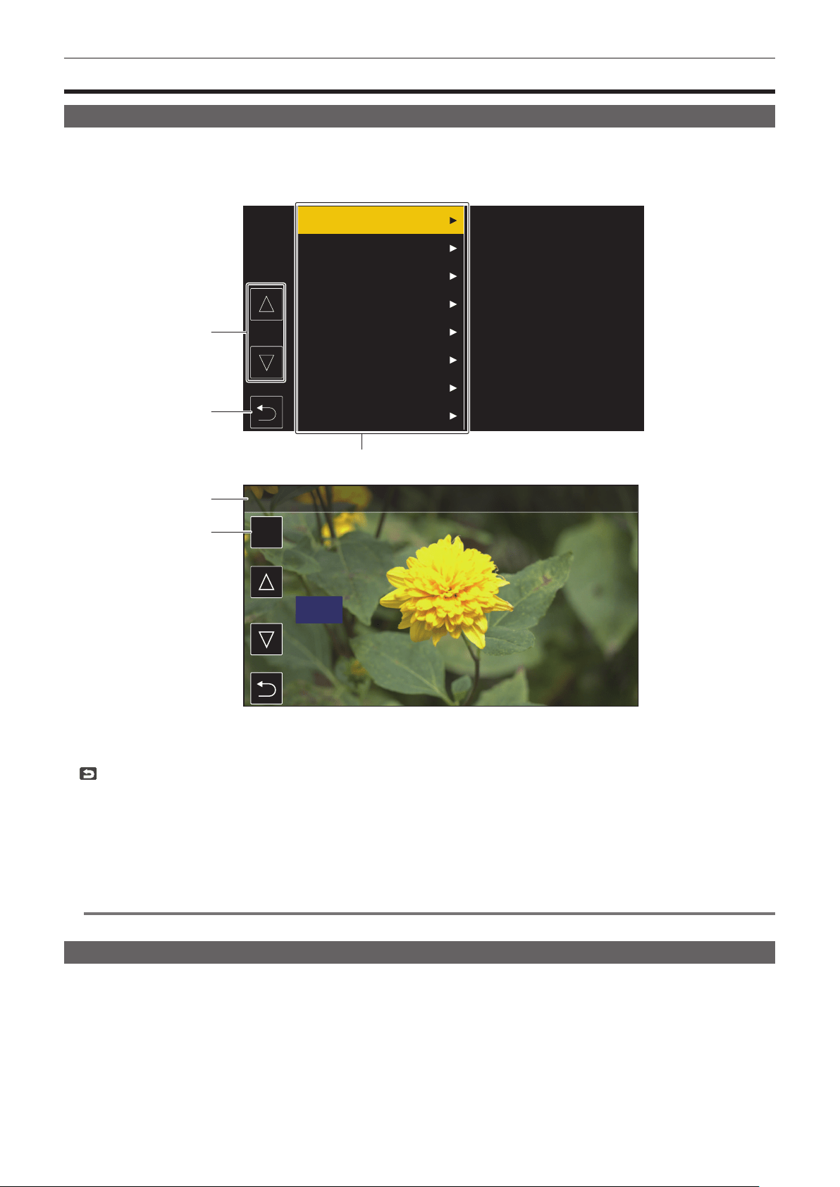
– 61 –
Chapter 4 Operation — Menu display
Menu display
Displaying the menu
Displays the menu, and select the menu or item to set.
1
Press the <MENU> button when not recording.
The menu is displayed.
SET
50
4
3
5
1
2
CAMERA
SCENE FILE
AUDIO
VIDEO OUT/LCD/VF
RECORDING
NETWORK
SYSTEM
OTHERS
MENU>CAMERA>LENS/IRIS>A.IRIS LEVEL
1 [`]/[{]
Toggles the page or changes the value when selected.
These button icons are not available if they cannot be changed.
2
Returns to one level higher from the displayed menu when selected.
3 Menu
Moves to one level lower from the displayed menu, or to the setting screen when selected.
4 Level display
Displays the path of the menu to the currently displayed screen.
5 [SET]
Conrms the set value when selected.
@
NOTE
t The menu displayed in gray characters cannot be changed.
Initializing the menu
Most of the setting values of the menu can be returned to the factory setting status. Refer to “Target items for scene le/setup le/initialization”
(page 116).
1
Select the [OTHERS] menu → [MENU INITIALIZE].
2
Select [SET] when the confirmation message is displayed.
The setting value of the menu is returned to the factory setting.
– 62 –
Chapter 4 Operation — Menu settings
Menu settings
[THUMBNAIL] menu
Performs conrmation or deleting of the recording clip.
This menu can be set when the thumbnail screen is displayed.
[PLAYBACK]
Sets the playback of recorded clips.
[CLIP SEL]
Selects a clip to be displayed on the thumbnail screen.
It is always displayed in [ALL SLOT] when switched from the camera image screen to the thumbnail screen.
[ALL SLOT] Displays all the clips recorded on every memory card in each card slot.
[SLOT1] Displays only the clips recorded on the memory card in card slot 1.
[SLOT2] Displays only the clips recorded on the memory card in card slot 2.
[SLOT3] Displays only the clips recorded on the memory card in card slot 3.
[SAME FORMAT] Displays only the clips recorded in the same format as the system format.
Clips recorded in the same format means that each item of the [SYSTEM] menu → [FREQUENCY]/[FILE FORMAT]/[REC
FORMAT]/[AUDIO SAMPLE RES.] matches the current setting status.
[MARKED] Displays only the clips with a shot mark attached.
(Factory setting: [ALL SLOT])
[RESUME PLAY]
Select if the playback is to start from the position the playback has stopped or not.
[ON] Plays back from the position where playback has stopped.
[OFF] Always starts the playback from the beginning of the clip.
(Factory setting: [OFF])
[CLIP]
The clip can be protected or copied to a different memory card.
[PROTECT] [SELECT] Protect the clip so it is not mistakenly deleted.
Select the clip to protect, and set the protect.
[DELETE] [ALL] Deletes all the clips displayed in the thumbnail screen.
The clip that is not displayed in the thumbnail screen is not deleted.
[SELECT] Select the clip to delete, and delete it.
[COPY] [ALL] Copies all clips to a different memory card.
[SELECT] Selects the clip to copy, and copies the clip to a different memory card.
Select [SLOT2→SLOT1] or [SLOT3→SLOT1] to copy a clip recorded spanning over
card slot 2 and card slot 3 to the expressP2 card in the card slot 1 while recording in P2
format.
An error occurs at the start of the copy process if [SLOT2→SLOT3] or [SLOT3→SLOT2]
is selected.
[REPAIR]
Repairs a clip displaying
caused by the sudden power loss, etc., during recording in
P2 format.
[RE-CONNECT] [SELECT] While recording in P2 format, a clip recorded over multiple microP2 cards may not be
recognized as a continuous clip, and may display
.
Restores as a continuous clip by selecting the clips to re-connect.
[INFORMATION] Displays the detailed information of the clip.
@
NOTE
t Clips in P2 format cannot be protected.
t Clips in MOV format cannot be copied.
[DISPLAY]
Sets the display of the thumbnail screen.
[DATA]
Selects the content to be displayed in the time code display area.
[START TC] Displays the time code value at the start of the recording.
[CLIP NAME] Displays clip names.
(Factory setting: [START TC])

– 63 –
Chapter 4 Operation — Menu settings
[CAMERA] menu
Sets the basic camera function.
This menu cannot be set when the thumbnail screen is displayed.
[SHUTTER SPEED]
The items that can be set in [POSITION1] to [POSITION6] are as follows.
f When the [SYSTEM] menu → [FREQUENCY] → [59.94Hz] is set
-[OFF], [1/100], [1/120], [1/250], [1/500], [1/1000], [1/2000], [HALF]
f When the [SYSTEM] menu → [FREQUENCY] → [50.00Hz] is set
-[OFF], [1/60], [1/120], [1/250], [1/500], [1/1000], [1/2000], [HALF]
[SYNCHRO SCAN] [SYNCHRO SCAN] is assigned as the shutter speed selected by the <SHUTTER> switch.
The items that can be set are as follows.
f [ON], [OFF]
(Factory setting: [ON])
[POSITION1] Sets the shutter speed of [POSITION1].
f The factory setting varies depending on the [SYSTEM] menu → [FREQUENCY] setting.
(Factory setting: [1/100] (when [59.94Hz] is set), [1/60] (when [50.00Hz] is set))
[POSITION2] Sets the shutter speed of [POSITION2].
(Factory setting: [1/120])
[POSITION3] Sets the shutter speed of [POSITION3].
(Factory setting: [1/250])
[POSITION4] Sets the shutter speed of [POSITION4].
(Factory setting: [1/500])
[POSITION5] Sets the shutter speed of [POSITION5].
(Factory setting: [1/1000])
[POSITION6] Sets the shutter speed of [POSITION6].
(Factory setting: [1/2000])
[SW MODE]
[RET SW]
Sets the function when the <RET> button on the lens is pressed.
[INHIBIT] Does not assign a function.
[D.ZOOM] Assigns the digital zoom function. Zooms in on the eld angle by 2x, 3x and 4x vertically and horizontally.
[FOCUS ASSIST] Displays/hides the focus assist display.
Select the type of display in the [VIDEO OUT/LCD/VF] menu → [FOCUS ASSIST] → [FOCUS ASSIST SELECT].
[REC CHECK] Automatically plays back the last approximately three seconds of the previously shot clip.
[LCD/VF DETAIL] Emphasizes the contour of the image in the viewnder or LCD monitor to make it easier to focus.
[VF COLOR] Selects whether to display viewnder images in color or in black and white.
This is interlocked with the setting value in the [VIDEO OUT/LCD/VF] menu → [VF COLOR].
[STREAMING START] Assigns the function for starting or stopping streaming from the camera.
This is interlocked with the setting value in the [NETWORK] menu → [STREAMING] → [START].
(Factory setting: [REC CHECK])
[S.BLK LEVEL]
Sets the super black level.
The items that can be set are as follows.
f [−30], [−20], [−10]
(Factory setting: [−10])
@
NOTE
t This cannot be set when the [SYSTEM] menu → [COLOR SETTING] → [V-Log] is set.
[AUTO KNEE SW]
Enables/disables the auto knee function and the dynamic range stretcher function.
[DRS] The dynamic range stretcher function is enabled when the <OUTPUT>/<AUTO KNEE> switch is set to <ON>.
[ON] The auto knee function is enabled when the <OUTPUT>/<AUTO KNEE> switch is set to <ON>.
[OFF] The auto knee function and the dynamic range stretcher function are not enabled even if the <OUTPUT>/<AUTO KNEE>
switch is set to <ON>.
(Factory setting: [ON])
@
NOTE
t This cannot be set when the [SYSTEM] menu → [COLOR SETTING] → [V-Log] is set.
[SHD,ABB SW CTL]
Sets whether to automatically adjust black shading when the <AUTO W/B BAL> switch is pressed toward <ABB> side for two seconds or more.
– 64 –
Chapter 4 Operation — Menu settings
The items that can be set are as follows.
f [ON], [OFF]
(Factory setting: [OFF])
[S.GAIN OFF]
Selects a method to release super gain mode.
[L/M/H] The super gain mode is released in following cases.
f When the <GAIN> switch setting is changed
f When the USER button assigned with [S.GAIN] is pressed
[S.GAIN] The super gain mode is released only when the USER button assigned with [S.GAIN] is pressed.
(Factory setting: [L/M/H])
@
NOTE
t This cannot be set when the [SCENE FILE] menu → [GAIN/ISO MODE] → [ISO] is set.
[DS.GAIN OFF]
Selects a method to release digital super gain mode (accumulated gain).
[L/M/H] The digital super gain mode is released in following cases.
f When the <GAIN> switch setting is changed
f When the USER button assigned with [DS.GAIN] is pressed
[DS.GAIN] The digital super gain mode is released only when the USER button assigned with [DS.GAIN] is pressed.
(Factory setting: [DS.GAIN])
@
NOTE
t This cannot be set when the [SCENE FILE] menu → [GAIN/ISO MODE] → [ISO] is set.
[D.ZOOM]
Selects the zoom ratio for when the USER button assigned with [D.ZOOM] is pressed.
The items that can be set are as follows.
f [×2], [×3], [×4], [ALL]
(Factory setting: [ALL])
[USER SW]
The function to be assign to the USER button can be set.
Following functions can be assigned.
f [INHIBIT], [DRS], [FBC], [S.GAIN], [ATW], [ATW LOCK], [Y GET], [D.ZOOM], [DS.GAIN], [S.IRIS], [I.OVR], [S.BLK], [B.GAMMA], [FOCUS ASSIST],
[C.TEMP], [ADAPTIVE MATRIX], [PRE REC], [REC CHECK], [DEL LAST CLIP], [SLOT SEL], [REC SW], [WFM], [LCD/VF HDR], [LCD/VF DETAIL],
[VF COLOR], [INDICATOR SW], [LOAD SETUP FILE], [LCD BACKLIGHT], [CARD READER MODE], [STREAMING START], [LCD/VF V-Log], [SHOT
MARK]
For details, refer to “Assigning function to the USER buttons” (page 136).
[USER1] Sets the function to assign to the <USER 1> button.
(Factory setting: [FOCUS ASSIST])
[USER2] Sets the function to assign to the <USER 2> button.
(Factory setting: [S.GAIN])
[USER3] Sets the function to assign to the <USER 3> button.
(Factory setting: [DS.GAIN])
[USER4] Sets the function to assign to the <USER 4> button.
(Factory setting: [Y GET])
[USER5] Sets the function to assign to the <USER 5> button.
(Factory setting: [WFM])
[WHITE BALANCE MODE]
[FILTER INH]
Selects whether to hold or not hold the white balance memory (Ach and Bch) data for each CC lter.
[ON] Holds Ach and Bch memory data (two memories), regardless of the CC lter.
[OFF] Holds Ach and Bch memory data (eight memories), for each CC lter.
(Factory setting: [ON])
[SHOCKLESS AWB]
When the position of the <WHITE BAL> switch is changed, set the time until it transfers to the white balance condition at the changed position.
[FAST] Transfers to the white balance condition in approximately one second.
[NORMAL] Transfers to the white balance condition in approximately two seconds.
[SLOW1] Transfers to the white balance condition in approximately three seconds.
[SLOW2] Transfers to the white balance condition in approximately ten seconds.

– 65 –
Chapter 4 Operation — Menu settings
[SLOW3] Transfers to the white balance condition in approximately 20 seconds.
[OFF] Transfers immediately.
(Factory setting: [NORMAL])
[AWB AREA]
Selects the detection area to perform the auto adjustment of the white balance.
[25%] Detects 25% of the area near screen center.
[50%] Detects 50% of the area near screen center.
[90%] Detects 90% of the screen area.
(Factory setting: [25%])
[ATW]
Assigns the setting of the auto tracking white balance function to the <WHITE BAL> switch.
The items that can be set are as follows.
f [Ach], [Bch], [PRE], [OFF]
(Factory setting: [OFF])
[ATW SPEED]
Sets the control speed of the auto tracking white balance function.
The items that can be set are as follows.
f [FAST], [NORMAL], [SLOW]
(Factory setting: [NORMAL])
[ATW TARGET R]
Finely adjusts the Rch output for convergence with the auto tracking white balance operation.
The items that can be set are as follows.
f [−10]…[+10]
(Factory setting: [0])
[ATW TARGET B]
Finely adjusts the Bch output for convergence with the auto tracking white balance operation.
The items that can be set are as follows.
f [−10]…[+10]
(Factory setting: [0])
[W.BAL PRESET]
Sets the color temperature to be assigned to <PRST> of the <WHITE BAL> switch.
The items that can be set are as follows.
f [3200K], [5600K], [VAR]
(Factory setting: [3200K])
[W.BAL VAR]
Sets the value of [VAR] in [W.BAL PRESET].
Enabled when [W.BAL PRESET] is set to [VAR] and the <WHITE BAL> switch is at <PRST>.
The items that can be set are as follows.
f When the <CC FILTER> dial is set to <A>
-[2000K]…[15000K]
f When the <CC FILTER> dial is set to <B>
-[2380K]…[>15000K]
f When the <CC FILTER> dial is set to <C>
-[2730K]…[>15000K]
f When the <CC FILTER> dial is set to <D>
-[2890K]…[>15000K]
(Factory setting: [3200K])
[USER SW GAIN]
[S.GAIN]
Selects the super gain value to enable when [S.GAIN] is assigned to the USER button.
f When set to [ALL], the display will switch in the order of [30dB], [36dB], [42dB], and normal gain every time the USER button is pressed.
The items that can be set are as follows.
f [30dB], [36dB], [42dB], [ALL]
(Factory setting: [ALL])
[DS.GAIN]
Selects the digital super gain value to enable when [DS.GAIN] is assigned to the USER button.
f When set to [ALL], the display will switch in the order of [6dB], [10dB], [12dB], [15dB], [20dB], [24dB], [28dB], [34dB], and normal gain every time the
USER button is pressed.
– 66 –
Chapter 4 Operation — Menu settings
The items that can be set are as follows.
f [6dB], [10dB], [12dB], [15dB], [20dB], [24dB], [28dB], [34dB], [ALL]
(Factory setting: [ALL])
[LENS/IRIS]
[A.IRIS LEVEL]
Sets the auto iris target value.
The items that can be set are as follows.
f [0]…[100]
(Factory setting: [50])
[A.IRIS PEAK/AVE]
Sets the ratio included in the peak for auto iris standard.
Larger the ratio, it will correspond to a peak within the iris detection window.
Smaller the ratio, it will correspond to a average value within the iris detection window.
The items that can be set are as follows.
f [0]…[100]
(Factory setting: [30])
[A.IRIS WINDOW]
Selects the auto iris detection window.
[NORMAL1] Window that is around center of the screen.
[NORMAL2] Window that is around bottom of the screen.
[CENTER] Window that is a spot around center of the screen.
(Factory setting: [NORMAL1])
[S.IRIS LEVEL]
Sets the super iris (backlight compensation) target value.
The items that can be set are as follows.
f [0]…[100]
(Factory setting: [70])
[IRIS GAIN]
Sets whether to perform the [IRIS GAIN] adjustment on the camera or on the lens.
The items that can be set are as follows.
f [CAM], [LENS]
(Factory setting: [LENS])
[IRIS GAIN VALUE]
Selects the [IRIS GAIN] adjustment value.
This setting is enabled when [IRIS GAIN] is set to [CAM].
The items that can be set are as follows.
f [0]…[20]
(Factory setting: [10])
[LENS ADJ.]
[F2.8 ADJ.]
Iris is set to F2.8 only when set to [ON].
(Adjusts the iris so that it becomes F2.8 at the lens side)
When moved from the [F2.8 ADJ.] setting screen, it is forcefully switched to [OFF].
The items that can be set are as follows.
f [ON], [OFF]
(Factory setting: [OFF])
[F16 ADJ.]
Iris is set to F16 only when set to [ON].
(Adjusts the iris so that it becomes F16 at the lens side)
When moved from the [F16 ADJ.] setting screen, it is forcefully switched to [OFF].
The items that can be set are as follows.
f [ON], [OFF]
(Factory setting: [OFF])
[LENS FILE ADJ.]
@
NOTE
t Data adjusted with [LENS FILE ADJ.] can be saved as a lens le to the SD card.
– 67 –
Chapter 4 Operation — Menu settings
[LENS FILE ADJ. MODE]
Selects the mode to adjust the lens.
When transferred from the [LENS FILE ADJ. MODE] setting screen, it is forcefully switched to [OFF].
[ON]
The gains of Rch and Bch adjusted in the [SCENE FILE] menu → [RB GAIN CONTROL SETTING] and the are level of
Rch, Gch, and Bch adjusted in the [SCENE FILE] menu → [RGB BLACK CONTROL SETTING] are disabled.
[OFF]
The gains of Rch and Bch adjusted in the [SCENE FILE] menu → [RB GAIN CONTROL SETTING] and the are level of
Rch, Gch, and Bch adjusted in the [SCENE FILE] menu → [RGB BLACK CONTROL SETTING] are enabled.
(Factory setting: [OFF])
[LENS R GAIN OFFSET]
Corrects the Rch sensitivity of the lens to use.
The items that can be set are as follows.
f [−200]…[200]
(Factory setting: [0])
[LENS B GAIN OFFSET]
Corrects the Bch sensitivity of the lens to use.
The items that can be set are as follows.
f [−200]…[200]
(Factory setting: [0])
[LENS R FLARE]
Adjusts the Rch are level.
The items that can be set are as follows.
f [0]…[100]
(Factory setting: [0])
[LENS G FLARE]
Adjusts the Gch are level.
The items that can be set are as follows.
f [0]…[100]
(Factory setting: [0])
[LENS B FLARE]
Adjusts the Bch are level.
The items that can be set are as follows.
f [0]…[100]
(Factory setting: [0])
[AGC]
[AGC]
Sets the operation of the auto gain control.
[ON] Performs the operation of the [AGC] function that automatically adjusts camera gain.
[OFF] Does not perform the operation of the [AGC] function that automatically adjusts camera gain.
(Factory setting: [OFF])
@
NOTE
t The setting is xed to [OFF] when the [SCENE FILE] menu → [GAIN/ISO MODE] → [ISO] is set.
[AGC LIMIT]
Sets the maximum gain value during [AGC] operation.
The items that can be set are as follows.
f [3dB], [6dB], [12dB], [18dB]
(Factory setting: [6dB])
@
NOTE
t This cannot be set when the [SCENE FILE] menu → [GAIN/ISO MODE] → [ISO] is set.
[AGC POINT]
Sets the F value to switch control from auto iris to [AGC] during [AGC] operation.
The items that can be set are as follows.
f [F2.8], [F4.0], [F5.6]
(Factory setting: [F4.0])
@
NOTE
t This cannot be set when the [SCENE FILE] menu → [GAIN/ISO MODE] → [ISO] is set.
– 68 –
Chapter 4 Operation — Menu settings
[BLACK SHADING]
[CORRECT]
Enables/disables the black shading correction.
The items that can be set are as follows.
f [ON], [OFF]
(Factory setting: [ON])
[DETECTION]
Executes the black shading correction.
[WHITE SHADING]
[CORRECT] Enables/disables the white shading correction.
The items that can be set are as follows.
f [ON], [OFF]
(Factory setting: [ON])
[R H SAW] Performs the white shading correction manually.
Adjusts sawtooth waveforms and parabolic waveforms of RGB channels in the horizontal and vertical directions.
The items that can be set are as follows.
f [−255]…[255]
(Factory setting: [0])
[R H PARA]
[R V SAW]
[R V PARA]
[G H SAW]
[G H PARA]
[G V SAW]
[G V PARA]
[B H SAW]
[B H PARA]
[B V SAW]
[B V PARA]
[CAC ADJ.]
[CAC CONTROL]
Switches [ON]/[OFF] of the chromatic aberration compensation (CAC).
[ON] Performs the chromatic aberration compensation.
[OFF] Does not perform the chromatic aberration compensation.
(Factory setting: [ON])
[LIST/DELETE]
Views the list of CAC le stored in the camera memory or deletes the le with the number selected from the list of the CAC le.
The items that can be selected are as follows.
f [No1]…[No32]
[SCENE FILE] menu
Sets the detailed image quality adjustment of the camera video.
This menu cannot be set when the thumbnail screen is displayed.
For the factory settings, refer to “Factory setting value of the scene le” (page 113).
[FILE SELECT]
Selects the scene le (1 to 6).
The items that can be set are as follows.
f [F1:], [F2:], [F3:], [F4:], [F5:], [F6:]
[NAME EDIT]
Edits the name of the scene le selected in the scene le menu. (Maximum eight characters)
[LOAD/SAVE/INITIALIZE]
Loads/saves/initializes the setting values of the scene le assigned to the current scene le number (any one from 1 to 6).
[LOAD] Loads the scene le saved on the camera memory.
[SAVE] Saves the current setting values as a scene le to the camera memory.
[INITIALIZE] Initializes the selected scene les (1 to 6) to the factory settings.
[SYNC SCAN TYPE]
Switches the synchro scan display settings.

– 69 –
Chapter 4 Operation — Menu settings
[sec] Displays in time.
[deg] Displays in the shutter open angle.
[SYNC SCAN]
Displays the shutter speed of the synchro scan that is used when shooting video for television, etc.
The items that can be set are as follows.
f When [SYNC SCAN TYPE] is set to [sec] and the [SYSTEM] menu → [FREQUENCY] → [59.94Hz] is set
-59.94i/59.94p mode: [1/60.0] … [1/7200]
-29.97p mode: [1/30.0]…[1/7200]
-23.98p mode: [1/24.0]…[1/7200]
f When [SYNC SCAN TYPE] is set to [sec] and the [SYSTEM] menu → [FREQUENCY] → [50.00Hz] is set
-50i/50p mode: [1/50.0]…[1/7200]
-25p mode: [1/25.0]…[1/7200]
f When [SYNC SCAN TYPE] is set to [deg]
-[3.0d]…[360.0d]
[MASTER DTL]
Sets the level of the detail effect of the whole part.
The items that can be set are as follows.
f [−31]…[31]
@
NOTE
t This cannot be set when the [SYSTEM] menu → [COLOR SETTING] → [V-Log] is set.
[DTL CORING]
Sets the level of signal (including noise) that does not activate the detail effect.
The items that can be set are as follows.
f [0]…[60]
@
NOTE
t This cannot be set when the [SYSTEM] menu → [COLOR SETTING] → [V-Log] is set.
[DETAIL SETTING]
@
NOTE
t This cannot be set when the [SYSTEM] menu → [COLOR SETTING] → [V-Log] is set.
[DETAIL]
Sets [ON]/[OFF] of the detail function.
The items that can be set are as follows.
f [ON], [OFF]
[H.DTL LEVEL]
Sets the intensity of the detail level in the horizontal direction.
The items that can be set are as follows.
f [−7]…[7]
[V.DTL LEVEL]
Sets the intensity of the detail level in the vertical direction.
The items that can be set are as follows.
f [−7]…[7]
[DTL FREQ.]
Sets the thickness of the detail.
The items that can be set are as follows.
f [−7]…[7]
[LEVEL DEPEND.]
When the detail of luminosity signal is emphasized, details in the darker areas are compressed.
Details of bright areas are compressed more when the value set for [LEVEL DEPEND.] is larger.
The items that can be set are as follows.
f [−7]…[7]
[KNEE APE LEVEL]
Sets the detail level of high luminosity areas (high-brightness areas).
The items that can be set are as follows.
f [0]…[5]

– 70 –
Chapter 4 Operation — Menu settings
[DTL GAIN(+)]
Sets the detail level of the plus direction (to make brighter).
The items that can be set are as follows.
f [−31]…[31]
[DTL GAIN(−)]
Sets the detail level of the minus direction (to make darker).
The items that can be set are as follows.
f [−31]…[31]
[SKIN TONE DTL A]
Selects the skin tone table that will display the skin tone detail.
Create the skin tone table with [DETECT TABLE]. You can shoot smoother skin tones by displaying the skin tone detail.
You can use only [SKIN TONE DTL A] or use a combination of [SKIN TONE DTL A] and [SKIN TONE DTL B] or a combination of [SKIN TONE DTL A]
and [SKIN TONE DTL C].
The items that can be set are as follows.
f [ON], [OFF]
@
NOTE
t The setting is xed to [OFF] when the [SYSTEM] menu → [COLOR SETTING] → [V-Log] is set.
[SKIN TONE DTL B]
Selects the skin tone table that will display the skin tone detail.
Create the skin tone table with [DETECT TABLE]. You can shoot smoother skin tones by displaying the skin tone detail.
You can use only [SKIN TONE DTL B] or use a combination of [SKIN TONE DTL B] and [SKIN TONE DTL A] or a combination of [SKIN TONE DTL B]
and [SKIN TONE DTL C].
The items that can be set are as follows.
f [ON], [OFF]
@
NOTE
t The setting is xed to [OFF] when the [SYSTEM] menu → [COLOR SETTING] → [V-Log] is set.
[SKIN TONE DTL C]
Selects the skin tone table that will display the skin tone detail.
Create the skin tone table with [DETECT TABLE]. You can shoot smoother skin tones by displaying the skin tone detail.
You can use only [SKIN TONE DTL C] or use a combination of [SKIN TONE DTL C] and [SKIN TONE DTL A] or a combination of [SKIN TONE DTL C]
and [SKIN TONE DTL B].
The items that can be set are as follows.
f [ON], [OFF]
@
NOTE
t The setting is xed to [OFF] when the [SYSTEM] menu → [COLOR SETTING] → [V-Log] is set.
[SKIN TONE ZEBRA]
Set to display a zebra pattern in the skin tone area displayed in the viewnder screen.
The zebra pattern is displayed when this item is set to [ON] and [SKIN TONE DTL A]/[SKIN TONE DTL B]/[SKIN TONE DTL C] is enabled.
The zebra pattern displays the area selected in [SKIN TONE DTL SETTING].
The items that can be set are as follows.
f [ON], [OFF]
@
NOTE
t The setting is xed to [OFF] when the [SYSTEM] menu → [COLOR SETTING] → [V-Log] is set.
[SKIN TONE DTL SETTING]
@
NOTE
t This cannot be set when the [SYSTEM] menu → [COLOR SETTING] → [V-Log] is set.
[DETECT TABLE]
Selects the skin tone table of the subject to set the skin tone detail.
The items that can be set are as follows.
f [A], [B], [C]
[SKIN DTL EFFECT]
Sets the effective level of the skin tone detail.
The items that can be set are as follows.
f [0]…[31]

– 71 –
Chapter 4 Operation — Menu settings
[I CENTER]
Sets the center position of the upper I axis (setting the area that applies the skin tone).
The items that can be set are as follows.
f [0]…[255]
[I WIDTH]
Sets the width of the area that displays the skin tone of the upper I axis that focus on [I CENTER].
The items that can be set are as follows.
f [1]…[3]
[Q WIDTH]
Sets the width of the area that displays the skin tone of the upper Q axis that focus on [I CENTER].
The items that can be set are as follows.
f [1]…[3]
[Q PHASE]
Sets the phase of the area that applies the skin tone related to the Q axis.
The items that can be set are as follows.
f [−128]…[127]
[RB GAIN CONTROL SETTING]
[R GAIN AWB PRE]
Sets the Rch gain when the <WHITE BAL> switch is set to <PRST>.
The items that can be set are as follows.
f [−200]…[200]
[B GAIN AWB PRE]
Sets the Bch gain when the <WHITE BAL> switch is set to <PRST>.
The items that can be set are as follows.
f [−200]…[200]
[R GAIN AWB A]
Sets the Rch gain when the <WHITE BAL> switch is set to <A>.
The items that can be set are as follows.
f [−200]…[200]
[B GAIN AWB A]
Sets the Bch gain when the <WHITE BAL> switch is set to <A>.
The items that can be set are as follows.
f [−200]…[200]
[R GAIN AWB B]
Sets the Rch gain when the <WHITE BAL> switch is set to <B>.
The items that can be set are as follows.
f [−200]…[200]
[B GAIN AWB B]
Sets the Bch gain when the <WHITE BAL> switch is set to <B>.
The items that can be set are as follows.
f [−200]…[200]
[AWB A GAIN OFFSET]
Sets the value of the Rch gain and Bch gain when the <WHITE BAL> switch is set to <A> and automatic white balance is performed.
[ON] Keeps the values set in [R GAIN AWB A] and [B GAIN AWB A].
[OFF] Sets the value of Rch gain and Bch gain to [0].
[AWB B GAIN OFFSET]
Sets the value of the Rch gain and Bch gain when the <WHITE BAL> switch is set to <B> and automatic white balance is performed.
[ON] Keeps the values set in [R GAIN AWB B] and [B GAIN AWB B].
[OFF] Sets the value of Rch gain and Bch gain to [0].
[COLOR TEMP Ach SETTING]
[COLOR TEMP]
Displays the color temperature when the <WHITE BAL> switch is <A> and automatic white balance is working, or when it is preset.
Also, in automatic white balance operation, the color temperature can be changed by changing the output balance of Rch and Bch.

– 72 –
Chapter 4 Operation — Menu settings
The items that can be set are as follows.
f When the <CC FILTER> dial is set to <A>
-[2000K]…[15000K]
f When the <CC FILTER> dial is set to <B>
-[2380K]…[>15000K]
f When the <CC FILTER> dial is set to <C>
-[2730K]…[>15000K]
f When the <CC FILTER> dial is set to <D>
-[2890K]…[>15000K]
[R GAIN]
Displays the output of Rch when the <WHITE BAL> switch is <A> and automatic white balance is working, or when it is preset.
In the automatic white balance operation, the color can also be changed on the Rch axis by changing the output of Rch.
The items that can be set are as follows.
f [−400]…[400]
[B GAIN]
Displays the output of Bch when the <WHITE BAL> switch is <A> and automatic white balance is working, or when it is preset.
In automatic white balance operation, the color can also be changed on the Bch axis by changing the output of Bch.
The items that can be set are as follows.
f [−400]…[400]
[G AXIS]
Displays the output of G axis when the <WHITE BAL> switch is <A> and automatic white balance is working, or when it is preset.
In the automatic white balance operation, the color can also be changed on the G axis by changing the output of Rch and Bch.
The items that can be set are as follows.
f [−400]…[400]
[COLOR TEMP Bch SETTING]
[COLOR TEMP]
Displays the color temperature when the <WHITE BAL> switch is <B> and automatic white balance is working, or when it is preset.
Also, in automatic white balance operation, the color temperature can be changed by changing the output balance of Rch and Bch.
The items that can be set are as follows.
f When the <CC FILTER> dial is set to <A>
-[2000K]…[15000K]
f When the <CC FILTER> dial is set to <B>
-[2380K]…[>15000K]
f When the <CC FILTER> dial is set to <C>
-[2730K]…[>15000K]
f When the <CC FILTER> dial is set to <D>
-[2890K]…[>15000K]
[R GAIN]
Displays the output of Rch when the <WHITE BAL> switch is <B> and automatic white balance is working, or when it is preset.
In automatic white balance operation, the color can also be changed on the Rch axis by changing the output of Rch.
The items that can be set are as follows.
f [−400]…[400]
[B GAIN]
Displays the output of Bch when the <WHITE BAL> switch is <B> and automatic white balance is working, or when it is preset.
In automatic white balance operation, the color can also be changed on the Bch axis by changing the output of Bch.
The items that can be set are as follows.
f [−400]…[400]
[G AXIS]
Displays the output of G axis when the <WHITE BAL> switch is <B> and automatic white balance is working, or when it is preset.
In the automatic white balance operation, the color can also be changed on the G axis by changing the output of Rch and Bch.
The items that can be set are as follows.
f [−400]…[400]
[CHROMA LEVEL]
Sets the chroma level of P
R
and P
B
signals.
The items that can be set are as follows.
f [−99%]…[99%], [OFF]
@
NOTE
t This cannot be set when the [SYSTEM] menu → [COLOR SETTING] → [V-Log] is set.

– 73 –
Chapter 4 Operation — Menu settings
[CHROMA PHASE]
Finely adjusts the chroma phase of the P
R
signal and P
B
signal.
The items that can be set are as follows.
f [−31]…[31]
@
NOTE
t This cannot be set when the [SYSTEM] menu → [COLOR SETTING] → [V-Log] is set.
[MATRIX]
@
NOTE
t This cannot be set when the [SYSTEM] menu → [COLOR SETTING] → [V-Log] is set.
[L MATRIX TABLE]
Selects the color correction table when the <GAIN> switch is set to <L>.
The items that can be set are as follows.
f [A], [B], [OFF]
[M MATRIX TABLE]
Selects the color correction table when the <GAIN> switch is set to <M>.
The items that can be set are as follows.
f [A], [B], [OFF]
[H MATRIX TABLE]
Selects the color correction table when the <GAIN> switch is set to <H>.
The items that can be set are as follows.
f [A], [B], [OFF]
[MATRIX TABLE]
Selects the color correction table.
The items that can be set are as follows.
f [A], [B]
[ADAPTIVE MATRIX]
Enables/disables the function to control the linear matrix in accordance with the shooting condition.
If [ADAPTIVE MATRIX] is assigned to the USER button, pressing the USER button switches [ON]/[OFF].
The items that can be set are as follows.
f [ON], [OFF]
[R-G]
Adjusts the linear matrix. (Red - Green)
The items that can be set are as follows.
f [−63]…[63]
[R-B]
Adjusts the linear matrix. (Red - Blue)
The items that can be set are as follows.
f [−63]…[63]
[G-R]
Adjusts the linear matrix. (Green - Red)
The items that can be set are as follows.
f [−63]…[63]
[G-B]
Adjusts the linear matrix. (Green - Blue)
The items that can be set are as follows.
f [−63]…[63]
[B-R]
Adjusts the linear matrix. (Blue - Red)
The items that can be set are as follows.
f [−63]…[63]
[B-G]
Adjusts the linear matrix. (Blue - Green)
The items that can be set are as follows.
f [−63]…[63]

– 74 –
Chapter 4 Operation — Menu settings
[COLOR CORRECTION]
@
NOTE
t This cannot be set when the [SYSTEM] menu → [COLOR SETTING] → [V-Log] is set.
[L COLOR CORRECT]
Enables/disables the color correction function when the <GAIN> switch is set to <L>.
The items that can be set are as follows.
f [ON], [OFF]
[M COLOR CORRECT]
Enables/disables the color correction function when the <GAIN> switch is set to <M>.
The items that can be set are as follows.
f [ON], [OFF]
[H COLOR CORRECT]
Enables/disables the color correction function when the <GAIN> switch is set to <H>.
The items that can be set are as follows.
f [ON], [OFF]
[PARAMETER]
Corrects the color saturation and hue.
The items that can be set are as follows.
f [−63]…[63]
[R] ([SAT]) Corrects red color saturation.
[R] ([PHASE]) Corrects the red hue.
[R-R-Mg] ([SAT]) Corrects the color saturation between red and “colors between red and magenta”.
[R-R-Mg] ([PHASE]) Corrects the hue between red and “colors between red and magenta”.
[R-Mg] ([SAT]) Corrects the color saturation between red and magenta.
[R-Mg] ([PHASE]) Corrects the hue between red and magenta.
[Mg] ([SAT]) Corrects magenta color saturation.
[Mg] ([PHASE]) Corrects the magenta hue.
[Mg-B] ([SAT]) Corrects the color saturation between magenta and blue.
[Mg-B] ([PHASE]) Corrects the hue between magenta and blue.
[B] ([SAT]) Corrects blue color saturation.
[B] ([PHASE]) Corrects the blue hue.
[B-Cy] ([SAT]) Corrects the color saturation between blue and cyan.
[B-Cy] ([PHASE]) Corrects the hue between blue and cyan.
[Cy] ([SAT]) Corrects cyan color saturation.
[Cy] ([PHASE]) Corrects the cyan hue.
[Cy-G] ([SAT]) Corrects the color saturation between cyan and green.
[Cy-G] ([PHASE]) Corrects the hue between cyan and green.
[G] ([SAT]) Corrects green color saturation.
[G] ([PHASE]) Corrects the green hue.
[G-Yl] ([SAT]) Corrects the color saturation between green and yellow.
[G-Yl] ([PHASE]) Corrects the hue between green and yellow.
[G-Yl-Yl] ([SAT]) Corrects the color saturation between “colors between green and yellow” and yellow.
[G-Yl-Yl] ([PHASE]) Corrects the hue between “colors between green and yellow” and yellow.
[Yl] ([SAT]) Corrects yellow color saturation.
[Yl] ([PHASE]) Corrects the yellow hue.
[Yl-Yl-R] ([SAT]) Corrects the color saturation between yellow and “colors between yellow and red”.
[Yl-Yl-R] ([PHASE]) Corrects the hue between yellow and “colors between yellow and red”.
[Yl-R] ([SAT]) Corrects the color saturation between yellow and red.
[Yl-R] ([PHASE]) Corrects the hue between yellow and red.
[Yl-R-R] ([SAT]) Corrects the color saturation between “colors between yellow and red” and red.
[Yl-R-R] ([PHASE]) Corrects the hue between “colors between yellow and red” and red.
[MASTER PED]
Sets the master pedestal.
The items that can be set are as follows.
f [−200]…[200]
@
NOTE
t This cannot be set when the [SYSTEM] menu → [COLOR SETTING] → [V-Log] is set.
– 75 –
Chapter 4 Operation — Menu settings
[RGB BLACK CONTROL SETTING]
@
NOTE
t This cannot be set when the [SYSTEM] menu → [COLOR SETTING] → [V-Log] is set.
[R PED]
Sets the Rch pedestal level.
The items that can be set are as follows.
f [−100]…[100]
[G PED]
Sets the Gch pedestal level.
The items that can be set are as follows.
f [−100]…[100]
[B PED]
Sets the Bch pedestal level.
The items that can be set are as follows.
f [−100]…[100]
[PEDESTAL OFFSET]
Sets the Rch, Gch, and Bch pedestal levels after adjusting the automatic black balance.
[ON] Keeps each of the values set in [R PED], [G PED], and [B PED].
[OFF] Sets the pedestal level of Rch, Gch, and Bch to [0].
[R FLARE]
Adjusts the Rch are level.
The adjusted value of this item is added to the are adjustment value adjusted in the [CAMERA] menu → [LENS FILE ADJ.].
The items that can be set are as follows.
f [−100]…[100]
[G FLARE]
Adjusts the Gch are level.
The adjusted value of this item is added to the are adjustment value adjusted in the [CAMERA] menu → [LENS FILE ADJ.].
The items that can be set are as follows.
f [−100]…[100]
[B FLARE]
Adjusts the Bch are level.
The adjusted value of this item is added to the are adjustment value adjusted in the [CAMERA] menu → [LENS FILE ADJ.].
The items that can be set are as follows.
f [−100]…[100]
[GAMMA MODE SEL]
Selects the gamma mode.
[HD] Sets the gamma characteristics for HD (High Denition).
[SD] Increases gain in darker areas more than HD gamma.
[FILMLIKE1] Sets the characteristics that reproduce more highlight areas compared to HD gamma.
[FILMLIKE2] Sets the characteristics that reproduce more highlight areas compared to [FILMLIKE1].
[FILMLIKE3] Sets the characteristics that reproduce more highlight areas compared to [FILMLIKE2].
[FILM-REC] Sets the cine gamma characteristics for lm.
[VIDEO-REC] Sets the cine gamma characteristics for video.
[HLG] Sets the hybrid log gamma (HLG) characteristics.
@
NOTE
t This cannot be set when the [SYSTEM] menu → [COLOR SETTING] → [V-Log] is set.
[GAMMA SETTING]
@
NOTE
t This cannot be set when the [SYSTEM] menu → [COLOR SETTING] → [V-Log] is set.
[MASTER GAMMA]
Sets the master gamma in 0.01 steps.
f Depending on the <GAIN> switch setting, it is linked to the setting value of [MASTER GAMMA] in [LOW SETTING]/[MID SETTING]/[HIGH SETTING].
The items that can be set are as follows.
f [0.30]…[0.75]
– 76 –
Chapter 4 Operation — Menu settings
[F-REC DYNAMIC LEVEL]
When [FILM-REC] is selected in [GAMMA MODE SEL], dynamic range is set.
No settings are changed if an item other than [FILM-REC] is selected.
The items that can be set are as follows.
f [200%] … [600%] (100% step)
[F-REC BLACK STR LEVEL]
When [FILM-REC] is selected in [GAMMA MODE SEL], black stretch is set.
No settings are changed if an item other than [FILM-REC] is selected.
The items that can be set are as follows.
f [0%]…[30%]
[V-REC KNEE SLOPE]
When [VIDEO-REC] is selected in [GAMMA MODE SEL], knee slope is set.
No settings are changed if an item other than [VIDEO-REC] is selected.
The items that can be set are as follows.
f [150%] … [500%] (50% step)
[V-REC KNEE POINT]
When [VIDEO-REC] is selected in [GAMMA MODE SEL], knee point is set.
No settings are changed if an item other than [VIDEO-REC] is selected.
The items that can be set are as follows.
f [30%]…[107%]
[BLACK GAMMA]
Sets the gamma curves of dark areas.
[−8]…[−1]
Compresses the dark area.
[0] Standard state
[1]…[8] Expands dark areas.
[B.GAMMA RANGE]
Sets the maximum level of compression/expansion.
[1] Around 20%
[2] Around 30%
[3] Around 40%
[KNEE SETTING]
@
NOTE
t This cannot be set when the [SYSTEM] menu → [COLOR SETTING] → [V-Log] is set.
[MANUAL KNEE]
Sets the knee operation mode.
The items that can be set are as follows.
f [ON], [OFF]
[KNEE MASTER POINT]
Sets the knee point position in 0.5% steps.
The items that can be set are as follows.
f [70.0%]…[107.0%]
[KNEE MASTER SLOPE]
Sets the knee inclination.
The items that can be set are as follows.
f [0]…[99]
[A.KNEE POINT]
Sets the auto knee point position in 1% steps.
This is enabled when the <OUTPUT>/<AUTO KNEE> switch is set to <CAM>/<ON>.
The items that can be set are as follows.
f [80%]…[107%]
[A.KNEE LEVEL]
Sets the auto knee level.
The items that can be set are as follows.
f [100]…[109]

– 77 –
Chapter 4 Operation — Menu settings
[A.KNEE RESPONSE]
Sets the auto knee response speed. The smaller the setting value, the faster the response speed is.
The items that can be set are as follows.
f [1]…[8]
[HLG KNEE SW]
Enables/disables the operation of knee for HLG.
The items that can be set are as follows.
f [ON], [OFF]
[HLG KNEE POINT]
Sets the position of the knee point for HLG.
The items that can be set are as follows.
f [55]…[100]
[HLG KNEE SLOPE]
Sets the inclination of knee for HLG.
The items that can be set are as follows.
f [0]…[100]
[HI-COLOR SW]
Selects [ON]/[OFF] of the mode that expands the color dynamic range.
The items that can be set are as follows.
f [ON], [OFF]
[WHITE CLIP SETTING]
@
NOTE
t This cannot be set when the [SYSTEM] menu → [COLOR SETTING] → [V-Log] is set.
[WHITE CLIP]
Turns the white clip function [ON]/[OFF]. The setting value of [WHITE CLIP LEVEL] is enabled when the function is [ON].
The items that can be set are as follows.
f [ON], [OFF]
[WHITE CLIP LEVEL]
Sets the white clip level.
The items that can be set are as follows.
f [90%]…[109%]
[LOW SETTING]
@
NOTE
t This cannot be set when the [SYSTEM] menu → [COLOR SETTING] → [V-Log] is set.
(excluding [MASTER GAIN])
[MASTER GAIN]
Sets the gain value to be assigned to <L> of the <GAIN> switch.
f When the [SCENE FILE] menu → [GAIN/ISO MODE] → [dB] is set
-[−6dB]…[30dB]
f When the [SCENE FILE] menu → [GAIN/ISO MODE] → [ISO] is set
-[ISO 400], [ISO 500], [ISO 640], [ISO 800], [ISO 1000], [ISO 1250], [ISO 1600], [ISO 2000], [ISO 2500], [ISO 3200], [ISO 4000], [ISO 5000], [ISO
6400], [ISO 8000], [ISO 10000], [ISO 12800]
[H.DTL LEVEL]
Sets the intensity of the detail level in the horizontal direction.
The items that can be set are as follows.
f [−7]…[7]
[V.DTL LEVEL]
Sets the intensity of the detail level in the vertical direction.
The items that can be set are as follows.
f [−7]…[7]
[DTL CORING]
Sets the level of signal (including noise) that does not activate the detail effect.
The items that can be set are as follows.
f [0]…[60]
[DTL FREQ.]
Sets the thickness of the detail.

– 78 –
Chapter 4 Operation — Menu settings
The items that can be set are as follows.
f [−7]…[7]
[LEVEL DEPEND.]
When the detail of luminosity signal is emphasized, details in the darker areas are compressed.
Details of bright areas are compressed more when the value set for [LEVEL DEPEND.] is larger.
The items that can be set are as follows.
f [−7]…[7]
[MASTER GAMMA]
Performs the setting of the master gamma in 0.01 steps.
The items that can be set are as follows.
f [0.30] … [0.75] (0.01 steps)
[BLACK GAMMA]
Sets the gamma curves of dark areas.
[−8]…[−1]
Compresses the dark area.
[OFF] Standard state
[1]…[8] Expands dark areas.
[B.GAMMA RANGE]
Sets the maximum level of compression/expansion.
[1] Around 20%
[2] Around 30%
[3] Around 40%
[MATRIX TABLE]
Selects the color correction table when the <GAIN> switch is set to <L>.
The items that can be set are as follows.
f [A], [B], [OFF]
[COLOR CORRECT]
Enables/disables the [COLOR CORRECTION] function when the <GAIN> switch is set to <L>.
The items that can be set are as follows.
f [ON], [OFF]
[MID SETTING]
@
NOTE
t This cannot be set when the [SYSTEM] menu → [COLOR SETTING] → [V-Log] is set.
(excluding [MASTER GAIN])
[MASTER GAIN]
Sets the gain value to be assigned to <M> of the <GAIN> switch.
f When the [SCENE FILE] menu → [GAIN/ISO MODE] → [dB] is set
-[−6dB]…[30dB]
f When the [SCENE FILE] menu → [GAIN/ISO MODE] → [ISO] is set
-[ISO 400], [ISO 500], [ISO 640], [ISO 800], [ISO 1000], [ISO 1250], [ISO 1600], [ISO 2000], [ISO 2500], [ISO 3200], [ISO 4000], [ISO 5000], [ISO
6400], [ISO 8000], [ISO 10000], [ISO 12800]
[H.DTL LEVEL]
Sets the intensity of the detail level in the horizontal direction.
The items that can be set are as follows.
f [−7]…[7]
[V.DTL LEVEL]
Sets the intensity of the detail level in the vertical direction.
The items that can be set are as follows.
f [−7]…[7]
[DTL CORING]
Sets the level of signal (including noise) that does not activate the detail effect.
The items that can be set are as follows.
f [0]…[60]
[DTL FREQ.]
Sets the thickness of the detail.
The items that can be set are as follows.
f [−7]…[7]

– 79 –
Chapter 4 Operation — Menu settings
[LEVEL DEPEND.]
When the detail of luminosity signal is emphasized, details in the darker areas are compressed.
Details of bright areas are compressed more when the value set for [LEVEL DEPEND.] is larger.
The items that can be set are as follows.
f [−7]…[7]
[MASTER GAMMA]
Performs the setting of the master gamma in 0.01 steps.
The items that can be set are as follows.
f [0.30] … [0.75] (0.01 steps)
[BLACK GAMMA]
Sets the gamma curves of dark areas.
[−8]…[−1]
Compresses the dark area.
[OFF] Standard state
[1]…[8] Expands dark areas.
[B.GAMMA RANGE]
Sets the maximum level of compression/expansion.
[1] Around 20%
[2] Around 30%
[3] Around 40%
[MATRIX TABLE]
Selects the color correction table when the <GAIN> switch is set to <M>.
The items that can be set are as follows.
f [A], [B], [OFF]
[COLOR CORRECT]
Enables/disables the [COLOR CORRECTION] function when the <GAIN> switch is set to <M>.
The items that can be set are as follows.
f [ON], [OFF]
[HIGH SETTING]
@
NOTE
t This cannot be set when the [SYSTEM] menu → [COLOR SETTING] → [V-Log] is set.
(excluding [MASTER GAIN])
[MASTER GAIN]
Sets the gain value to be assigned to <H> of the <GAIN> switch.
f When the [SCENE FILE] menu → [GAIN/ISO MODE] → [dB] is set
-[−6dB]…[30dB]
f When the [SCENE FILE] menu → [GAIN/ISO MODE] → [ISO] is set
-[ISO 400], [ISO 500], [ISO 640], [ISO 800], [ISO 1000], [ISO 1250], [ISO 1600], [ISO 2000], [ISO 2500], [ISO 3200], [ISO 4000], [ISO 5000], [ISO
6400], [ISO 8000], [ISO 10000], [ISO 12800]
[H.DTL LEVEL]
Sets the intensity of the detail level in the horizontal direction.
The items that can be set are as follows.
f [−7]…[7]
[V.DTL LEVEL]
Sets the intensity of the detail level in the vertical direction.
The items that can be set are as follows.
f [−7]…[7]
[DTL CORING]
Sets the level of signal (including noise) that does not activate the detail effect.
The items that can be set are as follows.
f [0]…[60]
[DTL FREQ.]
Sets the thickness of the detail.
The items that can be set are as follows.
f [−7]…[7]
[LEVEL DEPEND.]
When the detail of luminosity signal is emphasized, details in the darker areas are compressed.
– 80 –
Chapter 4 Operation — Menu settings
Details of bright areas are compressed more when the value set for [LEVEL DEPEND.] is larger.
The items that can be set are as follows.
f [−7]…[7]
[MASTER GAMMA]
Performs the setting of the master gamma in 0.01 steps.
The items that can be set are as follows.
f [0.30] … [0.75] (0.01 steps)
[BLACK GAMMA]
Sets the gamma curves of dark areas.
[−8]…[−1]
Compresses the dark area.
[OFF] Standard state
[1]…[8] Expands dark areas.
[B.GAMMA RANGE]
Sets the maximum level of compression/expansion.
[1] Around 20%
[2] Around 30%
[3] Around 40%
[MATRIX TABLE]
Selects the color correction table when the <GAIN> switch is set to <H>.
The items that can be set are as follows.
f [A], [B], [OFF]
[COLOR CORRECT]
Enables/disables the [COLOR CORRECTION] function when the <GAIN> switch is set to <H>.
The items that can be set are as follows.
f [ON], [OFF]
[GAIN/ISO MODE]
Switches the unit for gain value.
The items that can be set are as follows.
f [dB], [ISO]
@
NOTE
t The setting is xed to [dB] when the [SYSTEM] menu → [COLOR SETTING] → [NORMAL] is set.
[DRS]
Enables/disables the dynamic range stretcher function.
If functions are assigned to the USER buttons, [ON]/[OFF] can be switched using the USER button operations.
The items that can be set are as follows.
f [ON], [OFF]
@
NOTE
t The setting is xed to [OFF] when the [SYSTEM] menu → [COLOR SETTING] → [V-Log] is set.
[DRS EFFECT DEPTH]
Sets the compression level of the high luminosity areas of the dynamic range stretcher function.
By compressing the video signal levels of the high luminosity areas that are blown out in normal shooting, the dynamic range can be expanded.
The items that can be set are as follows.
f [1]…[3]
@
NOTE
t This cannot be set when the [SYSTEM] menu → [COLOR SETTING] → [V-Log] is set.
[DNR]
Changes the noise reduction setting and adjusts the noise reduction effect.
The items that can be set are as follows.
f [OFF], [1], [2]
[CAMERA SETTINGS]
[DETAIL]
Enables/disables the detail function.

– 81 –
Chapter 4 Operation — Menu settings
The items that can be set are as follows.
f [ON], [OFF]
@
NOTE
t The setting is xed to [OFF] when the [SYSTEM] menu → [COLOR SETTING] → [V-Log] is set.
[GAMMA]
Enables/disables the gamma correction.
The items that can be set are as follows.
f [ON], [OFF]
@
NOTE
t The setting is xed to [OFF] when the [SYSTEM] menu → [COLOR SETTING] → [V-Log] is set.
[TEST SAW]
Enables/disables the test signal.
The items that can be set are as follows.
f [ON], [OFF]
[FLARE]
Enables/disables the are correction.
The items that can be set are as follows.
f [ON], [OFF]
[H-F COMPE.]
Enables/disables the aperture correction.
The items that can be set are as follows.
f [ON], [OFF]
[AUDIO] menu
Sets the input/output function of audio.
[INPUT SETTINGS]
[FRONT MIC POWER]
Sets the phantom power supply of the front microphone.
The items that can be set are as follows.
f [ON], [OFF]
(Factory setting: [ON])
[REAR MIC POWER]
Sets the phantom power supply of the rear microphone.
When [OFF] is selected, the phantom power supply is not output even if the microphone input power selector switch is set to <+48V>.
The items that can be set are as follows.
f [ON], [OFF]
(Factory setting: [ON])
[FRONT MIC LEVEL]
Sets the input level of the external microphone connected to the front <MIC IN> terminal of the camera.
This is enabled only when an external microphone is connected to the <MIC IN> terminal.
The items that can be set are as follows.
f [−40dB], [−50dB], [−60dB]
(Factory setting: [−40dB])
[REAR MIC CH1/3 LEVEL]
Sets the audio input level of the external microphone connected to the rear <AUDIO IN CH1/3> terminal of the camera.
This is enabled only when the <LINE>/<MIC> selector switch is set to <MIC>.
The items that can be set are as follows.
f [−40dB], [−50dB], [−60dB]
(Factory setting: [−60dB])
[REAR MIC CH2/4 LEVEL]
Sets the audio input level of the external microphone connected to the rear <AUDIO IN CH2/4> terminal of the camera.
This is enabled only when the <LINE>/<MIC> selector switch is set to <MIC>.
The items that can be set are as follows.
f [−40dB], [−50dB], [−60dB]
(Factory setting: [−60dB])
[REAR LINE IN LEVEL]
Sets the audio input level of the device connected to the rear <AUDIO IN CH1/3>/<AUDIO IN CH2/4> terminal of the camera.
– 82 –
Chapter 4 Operation — Menu settings
This is enabled only when the <LINE>/<MIC> selector switch is set to <LINE>.
The items that can be set are as follows.
f [−3dB], [0dB], [4dB]
(Factory setting: [4dB] (when [AREA SETTINGS] is [AREA 1]/[AREA 2]/[AREA 4]), [0dB] (when [AREA SETTINGS] is [AREA 3]))
[WIRELESS WARN]
Selects whether to display a warning when the reception status of the wireless microphone receiver is poor.
The items that can be set are as follows.
f [ON], [OFF]
(Factory setting: [OFF])
[WIRELESS TYPE]
Selects the type of wireless microphone receiver.
[SINGLE] Selects a single channel type wireless microphone receiver.
[DUAL] Selects a double channel type wireless microphone receiver.
(Factory setting: [SINGLE])
[REC CH SETTINGS]
[VOL. SELECT]
Selects which audio channel to assign to the <AUDIO LEVEL CH1/3>/<AUDIO LEVEL CH2/4> dial and the <F.AUDIO LEVEL> dial.
[CH1/2] Assigns level adjustment of the audio channels 1 and 2. Audio channels 3 and 4 can be automatically adjusted or adjusted
by [CH3 LEVEL CONTROL] or [CH4 LEVEL CONTROL].
[CH3/4] Assigns level adjustment of the audio channels 3 and 4. Audio channels 1 and 2 can be automatically adjusted or adjusted
by [CH1 LEVEL CONTROL] or [CH2 LEVEL CONTROL].
(Factory setting: [CH1/2])
[FRONT VOL. CH1]
Selects if the <F.AUDIO LEVEL> dial is enabled against the audio signal input to the audio channel 1.
[FRONT] This is enabled when the <AUDIO IN CH1> switch is set to <FRONT>.
[W.L.] This is enabled when the <AUDIO IN CH1> switch is set to <W.L.>.
[REAR] This is enabled when the <AUDIO IN CH1> switch is set to <REAR>.
[ALL] The <F.AUDIO LEVEL> dial is enabled regardless of the setting of the <AUDIO IN CH1> switch.
[OFF] The <F.AUDIO LEVEL> dial is disabled regardless of the setting of the <AUDIO IN CH1> switch.
(Factory setting: [OFF])
[FRONT VOL. CH2]
Selects if the <F.AUDIO LEVEL> dial is enabled against the audio signal input to the audio channel 2.
[FRONT] This is enabled when the <AUDIO IN CH2> switch is set to <FRONT>.
[W.L.] This is enabled when the <AUDIO IN CH2> switch is set to <W.L.>.
[REAR] This is enabled when the <AUDIO IN CH2> switch is set to <REAR>.
[ALL] The <F.AUDIO LEVEL> dial is enabled regardless of the setting of the <AUDIO IN CH2> switch.
[OFF] The <F.AUDIO LEVEL> dial is disabled regardless of the setting of the <AUDIO IN CH2> switch.
(Factory setting: [OFF])
[FRONT VOL. CH3]
Selects if the <F.AUDIO LEVEL> dial is enabled against the audio signal input to the audio channel 3.
[FRONT] This is enabled when the <AUDIO IN CH3> switch is set to <FRONT>.
[W.L.] This is enabled when the <AUDIO IN CH3> switch is set to <W.L.>.
[REAR] This is enabled when the <AUDIO IN CH3> switch is set to <REAR>.
[ALL] The <F.AUDIO LEVEL> dial is enabled regardless of the setting of the <AUDIO IN CH3> switch.
[OFF] The <F.AUDIO LEVEL> dial is disabled regardless of the setting of the <AUDIO IN CH3> switch.
(Factory setting: [OFF])
[FRONT VOL. CH4]
Selects if the <F.AUDIO LEVEL> dial is enabled against the audio signal input to the audio channel 4.
[FRONT] This is enabled when the <AUDIO IN CH4> switch is set to <FRONT>.
[W.L.] This is enabled when the <AUDIO IN CH4> switch is set to <W.L.>.
[REAR] This is enabled when the <AUDIO IN CH4> switch is set to <REAR>.
[ALL] The <F.AUDIO LEVEL> dial is enabled regardless of the setting of the <AUDIO IN CH4> switch.
[OFF] The <F.AUDIO LEVEL> dial is disabled regardless of the setting of the <AUDIO IN CH4> switch.
(Factory setting: [OFF])

– 83 –
Chapter 4 Operation — Menu settings
[CH1 LEVEL]
Select auto/manual for the method to adjust the recording level of the audio channel 1.
The items that can be set are as follows.
f [AUTO], [MANUAL]
(Factory setting: [AUTO])
[CH2 LEVEL]
Select auto/manual for the method to adjust the recording level of the audio channel 2.
The items that can be set are as follows.
f [AUTO], [MANUAL]
(Factory setting: [AUTO])
[CH3 LEVEL]
Select auto/manual for the method to adjust the recording level of the audio channel 3.
The items that can be set are as follows.
f [AUTO], [MANUAL]
(Factory setting: [AUTO])
[CH4 LEVEL]
Select auto/manual for the method to adjust the recording level of the audio channel 4.
The items that can be set are as follows.
f [AUTO], [MANUAL]
(Factory setting: [AUTO])
[CH1 LEVEL CONTROL]
The recording level can be manually adjusted when [CH1 LEVEL] which adjusts the recording level of the audio channel 1 is set to [MANUAL].
The items that can be set are as follows.
f [0]…[100]
(Factory setting: [70])
[CH2 LEVEL CONTROL]
The recording level can be manually adjusted when [CH2 LEVEL] which adjusts the recording level of the audio channel 2 is set to [MANUAL].
The items that can be set are as follows.
f [0]…[100]
(Factory setting: [70])
[CH3 LEVEL CONTROL]
The recording level can be manually adjusted when [CH3 LEVEL] which adjusts the recording level of the audio channel 3 is set to [MANUAL].
The items that can be set are as follows.
f [0]…[100]
(Factory setting: [70])
[CH4 LEVEL CONTROL]
The recording level can be manually adjusted when [CH4 LEVEL] which adjusts the recording level of the audio channel 4 is set to [MANUAL].
The items that can be set are as follows.
f [0]…[100]
(Factory setting: [70])
[CH1 MIC LOWCUT]
Enables/disables the lowcut lter for audio channel 1.
The items that can be set are as follows.
f [FRONT], [W.L.], [REAR], [OFF]
(Factory setting: [OFF])
[CH2 MIC LOWCUT]
Enables/disables the lowcut lter for audio channel 2.
The items that can be set are as follows.
f [FRONT], [W.L.], [REAR], [OFF]
(Factory setting: [OFF])
[CH3 MIC LOWCUT]
Enables/disables the lowcut lter for audio channel 3.
The items that can be set are as follows.
f [FRONT], [W.L.], [REAR], [OFF]
(Factory setting: [OFF])
[CH4 MIC LOWCUT]
Enables/disables the lowcut lter for audio channel 4.
The items that can be set are as follows.
f [FRONT], [W.L.], [REAR], [OFF]
– 84 –
Chapter 4 Operation — Menu settings
(Factory setting: [OFF])
[CH1 LIMITER]
Enables/disables the limiter when the method to adjust the recording level for audio channel 1 is manual.
The items that can be set are as follows.
f [ON], [OFF]
(Factory setting: [OFF])
[CH2 LIMITER]
Enables/disables the limiter when the method to adjust the recording level for audio channel 2 is manual.
The items that can be set are as follows.
f [ON], [OFF]
(Factory setting: [OFF])
[CH3 LIMITER]
Enables/disables the limiter when the method to adjust the recording level for audio channel 3 is manual.
The items that can be set are as follows.
f [ON], [OFF]
(Factory setting: [OFF])
[CH4 LIMITER]
Enables/disables the limiter when the method to adjust the recording level for audio channel 4 is manual.
The items that can be set are as follows.
f [ON], [OFF]
(Factory setting: [OFF])
[HEAD ROOM]
Sets the headroom (standard level).
The items that can be set are as follows.
f [18dB], [20dB]
(Factory setting: [20dB] (when [AREA SETTINGS] is set to [AREA 1]/[AREA 2]), [18dB] (when [AREA SETTINGS] is set to [AREA 3]/[AREA 4]))
[OUTPUT SETTINGS]
[MONITOR SELECT]
Selects the signal format to output to the monitor when the <MONITOR SELECT> switch is set to <ST> (stereo).
The items that can be set are as follows.
f [STEREO], [MIX]
(Factory setting: [STEREO])
[AUDIO OUT LEVEL]
Selects the audio output level.
The items that can be set are as follows.
f [−3dB], [0dB], [4dB]
(Factory setting: [4dB] (when [AREA SETTINGS] is [AREA 1]/[AREA 2]/[AREA 4]), [0dB] (when [AREA SETTINGS] is [AREA 3]))
[HDMI OUT CH]
Selects the audio channel to be output from the <HDMI> terminal.
[CH1/2] Outputs the audio signals of the audio channel 1 and the audio channel 2 as stereo.
[CH3/4] Outputs the audio signals of the audio channel 3 and the audio channel 4 as stereo.
(Factory setting: [CH1/2])
[ALARM]
[BATTERY NEAR END]
Sets whether to sound the alarm when the remaining battery level is near end.
The items that can be set are as follows.
f [ON], [OFF]
(Factory setting: [OFF])
[BATTERY NEAR END CANCEL]
When set to [ON], the output alarm sound or warning displayed for the battery near end can be cancelled by pressing the <MARKER SEL>/<MODE
CHECK> switch to the <MCK> side.
The items that can be set are as follows.
f [ON], [OFF]
(Factory setting: [ON])
[BATTERY END]
Sets whether to sound the alarm when the remaining battery level is exhausted.
– 85 –
Chapter 4 Operation — Menu settings
The items that can be set are as follows.
f [ON], [OFF]
(Factory setting: [OFF])
[MEDIA NEAR END]
Sets whether to sound the alarm when the remaining memory card capacity is near end.
The items that can be set are as follows.
f [ON], [OFF]
(Factory setting: [OFF])
[MEDIA END]
Sets whether to sound the alarm when the remaining memory card capacity is exhausted.
The items that can be set are as follows.
f [ON], [OFF]
(Factory setting: [OFF])
[WARNING]
Sets whether to sound the alarm when a system error or warning occurs.
The items that can be set are as follows.
f [ON], [OFF]
(Factory setting: [OFF])
[VIDEO OUT/LCD/VF] menu
Congures the settings for the external output, the information to display in the LCD monitor or viewnder and the output format.
[SDI OUT1]
[OUTPUT SW]
Enables/disables the output from the <SDI OUT1> terminal.
[ON] Outputs the video.
[OFF] Does not output the video.
(Factory setting: [ON])
[OUT FORMAT]
Selects the signal to output from the <SDI OUT1> terminal. The item that can be selected varies depending on the setting of the [SYSTEM] menu →
[FREQUENCY]/[FILE FORMAT]/[REC FORMAT].
[3840×2160p] Outputs in 3840×2160p.
[1920×1080p] Outputs in 1920×1080p.
[1920×1080i] Outputs in 1920×1080i.
[1920×1080PsF] Outputs in 1920×1080PsF.
[1280×720p] Outputs in 1280×720p.
(Factory setting: [1920×1080i])
@
NOTE
t For the combinations that can be set, refer to “Format that can be output from the <SDI OUT1> terminal” (page 192).
[3G-SDI OUT]
Sets the format of the 3G-SDI signal output from the <SDI OUT1> terminal.
Can be set when the 3G-SDI signal is output.
[LEVEL-A] Selects the LEVEL-A method.
[LEVEL-B] Selects the LEVEL-B DL method.
(Factory setting: [LEVEL-B])
[SDI REC REMOTE]
Sets if the recording operation against the external equipment connected to the <SDI OUT1> terminal (such as recorder) is to be controlled or not.
[ON] Controls the recording operation of the external equipment.
[OFF] Does not control the recording operation of the external equipment.
(Factory setting: [OFF])
@
NOTE
t This cannot be set when set to the [RECORDING] menu → [REC FUNCTION] → [REC MODE] → [INTERVAL].
[SDI OUT CHAR]
Sets whether to superimpose the character to the output from the <SDI OUT1> terminal.
[ON] Superimposes.
– 86 –
Chapter 4 Operation — Menu settings
[OFF] Does not superimpose.
(Factory setting: [OFF])
[SDI OUT ZEBRA]
Sets whether to superimpose the zebra signal to the output from the <SDI OUT1> terminal.
The setting of the zebra signal is in accordance with the following setting in the [VIDEO OUT/LCD/VF] menu → [EI ASSIST].
f [ZEBRA1 DETECT], [ZEBRA2 DETECT], [ZEBRA2]
[ON] Superimposes.
[OFF] Does not superimpose.
(Factory setting: [OFF])
@
NOTE
t The setting is xed to [OFF] when the [SYSTEM] menu → [COLOR SETTING] → [V-Log] is set.
[SDI OUT HDR]
Sets the signal to output from the <SDI OUT1> terminal.
[SDR] Outputs in the standard dynamic range.
[HDR] Outputs in the high dynamic range.
(Factory setting: [HDR])
@
NOTE
t When the [SCENE FILE] menu → [GAMMA MODE SEL] is set to anything other than [HLG], the camera image is output in the standard dynamic
range.
t This cannot be set when the [SYSTEM] menu → [COLOR SETTING] → [V-Log] is set.
[MARKER SW]
Marker is displayed in the output from the <SDI OUT1> terminal.
The items that can be set are as follows.
f [ON], [OFF]
(Factory setting: [OFF])
[SDI OUT V-Log]
Sets the output signal from the <SDI OUT1> terminal when the [SYSTEM] menu → [COLOR SETTING] → [V-Log] is set.
[V-Log] Outputs in same color as the recording image.
[V-709] Outputs after converting to an image suitable for preview.
(Factory setting: [V-Log])
@
NOTE
t This cannot be set when the [SYSTEM] menu → [COLOR SETTING] → [NORMAL] is set.
[SDI OUT2]
[OUTPUT SW]
Enables/disables the output from the <SDI OUT2> terminal.
[ON] Outputs the video.
[OFF] Does not output the video.
(Factory setting: [ON])
[OUT FORMAT]
Sets the signal to output from the <SDI OUT2> terminal. The item that can be selected varies depending on the [SYSTEM] menu → [FREQUENCY]/
[FILE FORMAT]/[REC FORMAT] setting.
[1920×1080p] Outputs in 1920×1080p.
[1920×1080i] Outputs in 1920×1080i.
[1920×1080PsF] Outputs in 1920×1080PsF.
[1280×720p] Outputs in 1280×720p.
[720×480i] Outputs in 720×480i.
[720×576i] Outputs in 720×576i.
(Factory setting: [1920×1080i])
@
NOTE
t For the combinations that can be set, refer to “Format that can be output from the <SDI OUT2> terminal” (page 192).
[3G-SDI OUT]
Sets the format of the 3G-SDI signal output from the <SDI OUT2> terminal.

– 87 –
Chapter 4 Operation — Menu settings
Can be set when the 3G-SDI signal is output.
[LEVEL-A] Selects the LEVEL-A method.
[LEVEL-B] Selects the LEVEL-B DL method.
(Factory setting: [LEVEL-B])
[SD-SDI EDH]
Sets whether to superimpose EDH when output from the <SDI OUT2> terminal is the SD signal (480i and 576i).
[ON] Superimposes.
[OFF] Does not superimpose.
(Factory setting: [ON])
[SDI REC REMOTE]
Sets if the recording operation against the external equipment connected to the <SDI OUT2> terminal (such as recorder) is to be controlled or not.
[ON] Controls the recording operation of the external equipment.
[OFF] Does not control the recording operation of the external equipment.
(Factory setting: [OFF])
@
NOTE
t This cannot be set when set to the [RECORDING] menu → [REC FUNCTION] → [REC MODE] → [INTERVAL].
[SDI OUT ZEBRA]
Sets whether to superimpose the zebra signal to the output from the <SDI OUT2> terminal.
The setting of the zebra signal is in accordance with the following setting in the [VIDEO OUT/LCD/VF] menu → [EI ASSIST].
f [ZEBRA1 DETECT], [ZEBRA2 DETECT], [ZEBRA2]
[ON] Superimposes.
[OFF] Does not superimpose.
(Factory setting: [OFF])
@
NOTE
t The setting is xed to [OFF] when the [SYSTEM] menu → [COLOR SETTING] → [V-Log] is set.
[SDI OUT HDR]
Sets the signal to output from the <SDI OUT2> terminal.
[SDR] Outputs in the standard dynamic range.
[HDR] Outputs in the high dynamic range.
(Factory setting: [HDR])
@
NOTE
t The setting is xed to [SDR] when set to the following menu.
- [VIDEO OUT/LCD/VF] menu → [SDI OUT2] → [OUT FORMAT] → [720×480i]
- [VIDEO OUT/LCD/VF] menu → [SDI OUT2] → [OUT FORMAT] → [720×576i]
t The camera image is output in the standard dynamic range when the [SCENE FILE] menu → [GAMMA MODE SEL] is set to anything other than
[HLG].
t The setting is xed to [OFF] when the [SYSTEM] menu → [COLOR SETTING] → [V-Log] is set.
[MARKER SW]
Marker is displayed in the output from the <SDI OUT2> terminal.
The items that can be set are as follows.
f [ON], [OFF]
(Factory setting: [OFF])
[SDI OUT V-Log]
Sets the output signal from the <SDI OUT1> terminal when the [SYSTEM] menu → [COLOR SETTING] → [V-Log] is set.
[V-Log] Outputs in same color as the recording image.
[V-709] Outputs after converting to an image suitable for preview.
(Factory setting: [V-Log])
@
NOTE
t This cannot be set when the [SYSTEM] menu → [COLOR SETTING] → [NORMAL] is set.
[SDI OUTPUT ITEM]
Sets the character content to superimpose on the output signal of the <SDI OUT1>/<SDI OUT2>/<HDMI> terminals.
[MENU ONLY] Superimposes only the menu when displaying the menu. Normally, nothing is superimposed.

– 88 –
Chapter 4 Operation — Menu settings
[TC] Superimposes the time code. Superimposes only the menu when displaying the menu.
[STATUS] Displays the same contents as all the characters displayed in the viewnder and the LCD monitor. Superimposes only the
menu when displaying the menu.
(Factory setting: [MENU ONLY])
[HDMI OUT]
[SIGNAL SEL]
Sets the signal to output from the <HDMI> terminal.
The items that can be set are as follows.
f [SDI OUT1(2160p)], [SDI OUT2]
(Factory setting: [SDI OUT2])
@
NOTE
t [SDI OUT1(2160p)] can be selected only when [OUT FORMAT] of [SDI OUT1] is set to [3840×2160p].
This is xed to [SDI OUT2] when [OUT FORMAT] of [SDI OUT1] is set to anything other than [3840×2160p].
[HDMI TC OUT]
Sets if the time code information is output or not in the output from the <HDMI> terminal.
The items that can be set are as follows.
f [ON], [OFF]
(Factory setting: [OFF])
[HDMI REC REMOTE]
Sets if the recording operation against the external equipment connected to the <HDMI> terminal (such as recorder) is to be controlled or not. This can
be set when [HDMI TC OUT] in [HDMI OUT] is enabled.
[ON] Controls the recording operation of the external equipment.
[OFF] Does not control the recording operation of the external equipment.
(Factory setting: [OFF])
@
NOTE
t This cannot be set when set to the [RECORDING] menu → [REC FUNCTION] → [REC MODE] → [INTERVAL].
[SD DOWNCON MODE]
Sets the mode of the SD down converter output signal from the <SDI OUT2>/<HDMI OUT> terminal.
[SIDE CROP] Outputs an equal top and bottom width.
[LETTER BOX] Outputs an equal right and left width.
[SQUEEZE] Outputs by compressing in the horizontal direction to t the screen.
(Factory setting: [LETTER BOX])
[VF COLOR]
Selects whether to display viewnder images in color or in black and white.
[ON] Displays in color.
[OFF] Displays in black and white. The playback image, thumbnail screen, and menu display will be kept in color.
(Factory setting: [ON])
[LCD]
[BRIGHTNESS]
Adjusts the brightness of the LCD monitor.
The items that can be set are as follows.
f [−15]…[15]
(Factory setting: [0])
[COLOR LEVEL]
Adjusts the color level of the LCD monitor.
The items that can be set are as follows.
f [−15]…[15]
(Factory setting: [0])
[CONTRAST]
Adjusts the contrast of the LCD monitor.
The items that can be set are as follows.
f [−30]…[30]
(Factory setting: [0])

– 89 –
Chapter 4 Operation — Menu settings
[BACK LIGHT]
Adjusts the brightness of the LCD monitor backlight. [0] is the standard brightness.
The items that can be set are as follows.
f [−1], [0], [1], [2]
(Factory setting: [0])
[SELF SHOOT]
Sets the display of the LCD monitor when mirror shooting is performed.
[NORMAL] Does not invert the left and right sides.
[MIRROR] Inverts the left and right sides.
(Factory setting: [MIRROR])
[LCD/VF HDR]
Sets the output image from the LCD monitor and viewnder.
[SDR] Outputs in the standard dynamic range.
[HDR] Outputs in the high dynamic range.
(Factory setting: [HDR])
@
NOTE
t When the [SCENE FILE] menu → [GAMMA MODE SEL] is set to anything other than [HLG], the camera image is output in the standard dynamic
range.
t This cannot be set when the [SYSTEM] menu → [COLOR SETTING] → [V-Log] is set.
[LCD/VF V-Log]
Sets the output signal from the LCD monitor and viewnder when the [SYSTEM] menu → [COLOR SETTING] → [V-Log] is set.
[V-Log] Outputs in same color as the recording image.
[V-709] Outputs after converting to an image suitable for preview.
(Factory setting: [V-Log])
@
NOTE
t This cannot be set when the [SYSTEM] menu → [COLOR SETTING] → [NORMAL] is set.
[INDICATOR]
Selects the indicator to display in the output image.
[INDICATOR SW]
Selects the status display method.
[ON] Status is displayed constantly.
[OFF] Normally, status is not displayed. This is displayed when the mode check screen is displayed by pressing the <MARKER
SEL>/<MODE CHECK> switch toward the <MCK> side.
(Factory setting: [ON])
[TC]
Displays/hides the time code, user bits, and counter.
The items that can be set are as follows.
f [ON], [OFF]
(Factory setting: [OFF])
[TC ON COLOR BAR]
Selects whether to display the time code, user bits, and counter when color bar is output.
The items that can be set are as follows.
f [ON], [OFF]
(Factory setting: [OFF])
[REC STATUS]
Sets whether to display [REC] during recording.
[ON] [REC] is displayed.
[OFF] [REC] is not displayed.
However, [REC] is displayed when set to the [OTHERS] menu → [LED] → [REC TALLY] → [CHAR].
(Factory setting: [OFF])
[REC MEDIA]
Displays/hides the setting status of the memory card format to record.

– 90 –
Chapter 4 Operation — Menu settings
The items that can be set are as follows.
f [ON], [OFF]
(Factory setting: [ON])
[SLOT STATUS]
Displays/hides the status of the card slot and remaining memory card capacity.
The items that can be set are as follows.
f [ON], [OFF]
(Factory setting: [ON])
[2 SLOTS FUNC.]
Displays/hides the setting in the [RECORDING] menu → [2 SLOTS FUNC.].
The items that can be set are as follows.
f [ON], [OFF]
(Factory setting: [ON])
[STREAMING]
Displays/hides the streaming status.
The items that can be set are as follows.
f [ON], [OFF]
(Factory setting: [ON])
[NETWORK]
Displays/hides the connection status of the wired LAN, wireless LAN, and USB tethering.
The items that can be set are as follows.
f [ON], [OFF]
(Factory setting: [ON])
[BATTERY REMAIN]
Displays/hides the remaining battery level.
The items that can be set are as follows.
f [ON], [OFF]
(Factory setting: [ON])
[REC FORMAT]
Displays/hides the recording format settings.
The items that can be set are as follows.
f [ON], [OFF]
(Factory setting: [ON])
[CLIP NAME]
Displays/hides the clip le name to be recorded. Up to eight characters from the beginning of the le name are displayed.
The items that can be set are as follows.
f [ON], [OFF]
(Factory setting: [ON])
[BONDING DEVICE]
Displays/hides the status of the device acquired from the bonding device.
This is not displayed when the device status cannot be acquired from the bonding device even if [ON] is selected.
The items that can be set are as follows.
f [ON], [OFF]
(Factory setting: [ON])
[REC REMOTE]
Displays/hides the remote control status of the external equipment connected to the <SDI OUT1>/<SDI OUT2>/<HDMI> terminals.
The items that can be set are as follows.
f [ON], [OFF]
(Factory setting: [ON])
[REC MODE]
Displays/hides the status of the interval recording.
The items that can be set are as follows.
f [ON], [OFF]
(Factory setting: [ON])
[FBC]
Displays/hides the operation status of the ash band compensation function.
The items that can be set are as follows.
f [ON], [OFF]
(Factory setting: [ON])
– 91 –
Chapter 4 Operation — Menu settings
[HDR/DRS/V-Log]
Displays/hides the operation status of the high dynamic range recording function, dynamic range stretcher function, or V-Log recording function.
The items that can be set are as follows.
f [ON], [OFF]
(Factory setting: [ON])
[CAC]
Displays/hides the operation status of the chromatic aberration compensation function.
The items that can be set are as follows.
f [ON], [OFF]
(Factory setting: [ON])
[GAMMA MODE]
Displays/hides the gamma mode.
The items that can be set are as follows.
f [ON], [OFF]
(Factory setting: [ON])
[SCENE FILE]
Displays/hides scene le name.
The items that can be set are as follows.
f [ON], [OFF]
(Factory setting: [ON])
@
NOTE
t The setting is xed to [OFF] when the [SYSTEM] menu → [COLOR SETTING] → [V-Log] is set.
[AUDIO LEVEL METER]
Displays/hides the audio level meter.
The items that can be set are as follows.
f [ON], [OFF]
(Factory setting: [ON])
[GAIN]
Displays/hides the gain value and the digital super gain value.
The items that can be set are as follows.
f [ON], [OFF]
(Factory setting: [ON])
[SHUTTER]
Displays/hides the shutter speed.
The items that can be set are as follows.
f [ON], [OFF]
(Factory setting: [ON])
[IRIS]
Displays/hides the F value, operation status of the super iris, and the operation status of the super black.
[IRIS] Displays only the F value.
[S+IRIS] Displays all.
[S] Displays only the operation status of the super iris and operation status of the super black.
[OFF] Does not display.
(Factory setting: [S+IRIS])
@
NOTE
t The display of the F value and the display of the iris override are linked. The F value is displayed while changing the iris override even when set to [S]
or [OFF].
[ZOOM/FOCUS]
Switches the unit of zoom and focus values.
[NUMBER] Displays the zoom and focus in the position value between [000]/[00] and [999]/[99].
[mm/feet] Displays the zoom in units of millimeters and the focus in units of feet.
[mm/m] Displays the zoom in units of millimeters and the focus in units of meters.
[OFF] Does not display either the zoom or focus.
(Factory setting: [NUMBER])
[FILTER]
Displays/hides the positions of the ND lter and the CC lter.

– 92 –
Chapter 4 Operation — Menu settings
The items that can be set are as follows.
f [ON], [OFF]
(Factory setting: [ON])
[WHITE BALANCE]
Displays/hides the color temperature.
The items that can be set are as follows.
f [ON], [OFF]
(Factory setting: [ON])
[DATE/TIME]
Displays/hides the date and time.
Display order of the year, month, and date follows the setting in the [OTHERS] menu → [CLOCK] → [DATE FORMAT].
[OFF] Does not display the date and time.
[DATE] Displays only the date.
[TIME] Displays only the time.
[DATE&TIME] Displays the date and time.
(Factory setting: [OFF])
[SHOOTING MODE]
Displays/hides high-sensitivity mode.
The items that can be set are as follows.
f [ON], [OFF]
(Factory setting: [ON])
[EXTENDER]
Displays/hides the display whether lens extender function is active.
The items that can be set are as follows.
f [ON], [OFF]
(Factory setting: [ON])
[D.ZOOM]
Displays/hides the digital zoom ratio.
The items that can be set are as follows.
f [ON], [OFF]
(Factory setting: [ON])
[PLAYBACK STATUS]
Displays/hides the playback status.
The items that can be set are as follows.
f [ON], [OFF]
(Factory setting: [ON])
[SD CARD WARNING]
Toggles whether to display the warning when an SD card is inserted while [FILE FORMAT] is set to [P2].
The items that can be set are as follows.
f [ON], [OFF]
(Factory setting: [ON])
[MODE CHECK INDICATOR]
[STATUS]
Sets whether to display the STATUS screen when the <MARKER SEL>/<MODE CHECK> switch is pushed to the <MCK> side.
The items that can be set are as follows.
f [ON], [OFF]
(Factory setting: [ON])
[!LED]
Sets whether to display the !LED screen when the <MARKER SEL>/<MODE CHECK> switch is pushed to the <MCK> side.
The cause for the viewnder lamp is illuminated is displayed by [!] with black and white inverted.
The items that can be set are as follows.
f [ON], [OFF]
(Factory setting: [ON])
[FUNCTION]
Sets whether to display the FUNCTION screen when the <MARKER SEL>/<MODE CHECK> switch is pushed to the <MCK> side.
The items that can be set are as follows.
f [ON], [OFF]
– 93 –
Chapter 4 Operation — Menu settings
(Factory setting: [ON])
[AUDIO]
Sets whether to display the AUDIO screen when the <MARKER SEL>/<MODE CHECK> switch is pushed to the <MCK> side.
The items that can be set are as follows.
f [ON], [OFF]
(Factory setting: [ON])
[CAC]
Sets whether to display the CAC screen when the <MARKER SEL>/<MODE CHECK> switch is pushed to the <MCK> side.
The items that can be set are as follows.
f [ON], [OFF]
(Factory setting: [ON])
[USER SW STATUS]
Selects whether to display the SWITCH screen when the <MARKER SEL>/<MODE CHECK> switch is pushed to the <MCK> side.
The items that can be set are as follows.
f [ON], [OFF]
(Factory setting: [ON])
[NETWORK]
Selects whether to display the NETWORK screen when the <MARKER SEL>/<MODE CHECK> switch is pushed to the <MCK> side.
The items that can be set are as follows.
f [ON], [OFF]
(Factory setting: [ON])
[SDI OUT1 MARKER]
[CENTER MARKER]
Switch the type of the center marker.
[1]
+ (large)
[2] Open center (large)
[3]
+ (small)
[4] Open center (small)
[OFF] Does not display.
(Factory setting: [1])
[SAFETY MARKER]
Selects the type of frame for the safety zone marker.
[1] Box
[2] Corners
[OFF] Does not display.
(Factory setting: [2])
[SAFETY AREA]
Sets the size of the safety zone marker.
It can be set in 1% steps with the ratio of length to width constant.
The items that can be set are as follows.
f [80%]…[100%]
(Factory setting: [90%])
[FRAME MARKER]
Sets the aspect ratio of the frame marker. The frame marker is not displayed when [OFF] is selected.
The items that can be set are as follows.
f [4:3], [13:9], [14:9], [1.85:1], [2.35:1], [OFF]
(Factory setting: [OFF])
[FRAME COLOR]
Sets the color of the frame marker.
The items that can be set are as follows.
f [WHITE], [BLACK], [RED], [GREEN], [BLUE], [YELLOW]
(Factory setting: [WHITE])
[SDI OUT2 MARKER]
[CENTER MARKER]
Switch the type of the center marker.

– 94 –
Chapter 4 Operation — Menu settings
[1]
+ (large)
[2] Open center (large)
[3]
+ (small)
[4] Open center (small)
[OFF] Does not display.
(Factory setting: [1])
[SAFETY MARKER]
Selects the type of frame for the safety zone marker.
[1] Box
[2] Corners
[OFF] Does not display.
(Factory setting: [2])
[SAFETY AREA]
Sets the size of the safety zone marker.
It can be set in 1% steps with the ratio of length to width constant.
The items that can be set are as follows.
f [80%]…[100%]
(Factory setting: [90%])
[FRAME MARKER]
Sets the aspect ratio of the frame marker. The frame marker is not displayed when [OFF] is selected.
The items that can be set are as follows.
f [4:3], [13:9], [14:9], [1.85:1], [2.35:1], [OFF]
(Factory setting: [OFF])
[FRAME COLOR]
Sets the color of the frame marker.
The items that can be set are as follows.
f [WHITE], [BLACK], [RED], [GREEN], [BLUE], [YELLOW]
(Factory setting: [WHITE])
[LCD/VF MARKER]
[TABLE]
Selects the setting table of the marker select function. Check or set the details of [A]/[B] at subsequent settings.
The items that can be set are as follows.
f [A], [B]
(Factory setting: [A])
[CENTER MARKER]
Switch the type of the center marker.
[1]
+ (large)
[2] Open center (large)
[3]
+ (small)
[4] Open center (small)
[OFF] Does not display.
(Factory setting: [1])
[SAFETY MARKER]
Selects the type of frame for the safety zone marker.
[1] Box
[2] Corners
[OFF] Does not display.
(Factory setting: [2])
[SAFETY AREA]
Sets the size of the safety zone marker.
It can be set in 1% steps with the ratio of length to width constant.
The items that can be set are as follows.
f [80%]…[100%]
(Factory setting: [90%])
– 95 –
Chapter 4 Operation — Menu settings
[FRAME MARKER]
Sets the aspect ratio of the frame marker. The frame marker is not displayed when [OFF] is selected.
The items that can be set are as follows.
f [4:3], [13:9], [14:9], [1.85:1], [2.35:1], [OFF]
(Factory setting: [OFF])
[FRAME LEVEL]
Sets the level for outside of the frame marker.
[0] Equivalent to when signal is off (blanking status).
[1]…[14] Becomes brighter as the number becomes higher.
[15] Becomes same brightness as the center area.
(Factory setting: [15])
[FRAME COLOR]
Sets the color of the frame marker.
The items that can be set are as follows.
f [WHITE], [BLACK], [RED], [GREEN], [BLUE], [YELLOW]
(Factory setting: [WHITE])
[FOCUS ASSIST]
[FOCUS ASSIST SELECT]
Sets the focus assist method when the USER button assigned with [FOCUS ASSIST] is operated.
[EXPAND] Sets the enlarged display.
[PEAKING] Sets the peaking display.
[SQUARES] Sets the focus square display.
[EXPAND+PEAKING] Displays in the combination of [EXPAND] and [PEAKING].
[EXPAND+SQUARES] Displays in the combination of [EXPAND] and [SQUARES].
(Factory setting: [EXPAND])
[EXPAND MODE]
Sets the enlargement display function mode.
[10SEC] Disables the enlarged display function after ten seconds have elapsed.
[HOLD] Enables the enlarged display function until the <FOCUS ASSIST> button or the USER button assigned with [EXPAND] is
pressed.
[UNTIL REC] Enables the enlarged display function until recording starts.
(Factory setting: [10SEC])
[EXPAND VALUE]
Adjusts the enlargement factor of the enlarged display function.
The items that can be set are as follows.
f [×2], [×3], [×4]
(Factory setting: [×2])
[PEAKING LEVEL]
Sets the intensity of the peaking display.
The items that can be set are as follows.
f [LOW], [MID], [HIGH]
(Factory setting: [MID])
[PEAKING COLOR]
Sets the color of the peaking display.
The items that can be set are as follows.
f [RED], [GREEN], [WHITE]
(Factory setting: [RED])
[BLACK & WHITE]
Enables/disables the monochrome display.
[ON] Enables the monochrome display.
[OFF] Disables the monochrome display.
[DURING PEAKING] Enables the monochrome display while the peaking display is enabled.
(Factory setting: [OFF])
[DETAIL]
Sets the intensity of the contour for the video to make it easier to focus.

– 96 –
Chapter 4 Operation — Menu settings
The items that can be set are as follows.
f [ON], [OFF]
(Factory setting: [ON])
[DETAIL LEVEL]
Sets the intensity of the contours.
The items that can be set are as follows.
f [−3]…[3]
(Factory setting: [0])
[DETAIL FREQ.]
Adjusts the frequency of the contour highlights.
The items that can be set are as follows.
f [HIGH], [LOW]
(Factory setting: [LOW])
[EI ASSIST]
[ZEBRA1 DETECT]
Sets the detection level of zebra pattern 1.
The items that can be set are as follows.
f [0%]…[109%]
(Factory setting: [80%])
@
NOTE
t This cannot be set when the [SYSTEM] menu → [COLOR SETTING] → [V-Log] is set.
[ZEBRA2 DETECT]
Sets the detection level of zebra pattern 2.
The items that can be set are as follows.
f [0%]…[109%]
(Factory setting: [100%])
@
NOTE
t This cannot be set when the [SYSTEM] menu → [COLOR SETTING] → [V-Log] is set.
[ZEBRA2]
Enables/disables zebra pattern 2 and selects [SPOT].
The items that can be set are as follows.
f [ON], [SPOT], [OFF]
(Factory setting: [OFF])
@
NOTE
t This cannot be set when the [SYSTEM] menu → [COLOR SETTING] → [V-Log] is set.
[LOW LIGHT LEVEL]
Sets the amount of the light entering the camera to be the reference to display [LOW LIGHT].
The items that can be set are as follows.
f [OFF], [10%], [15%], [20%], [25%], [30%], [35%]
(Factory setting: [35%])
[WFM MODE]
Sets the display of the waveform monitor. Displaying of the waveform and the vector can be switched.
[WAVE] Displays the waveform.
[VECTOR] Displays the vector.
[WAVE/VECTOR] Displays the waveform and the vector.
The display switches in the order of waveform, vector, and no display every time the USER button assigned with [WFM] is
pressed.
(Factory setting: [WAVE])
[WFM TRANSPARENCE]
Sets the transmittance of the waveform monitor.
The items that can be set are as follows.
f [0%], [25%], [50%]
(Factory setting: [25%])
[Y GET UNIT]
Sets the unit of the brightness of Y GET.

– 97 –
Chapter 4 Operation — Menu settings
The items that can be set are as follows.
f [%], [STOP]
(Factory setting: [%])
@
NOTE
t This cannot be set when the [SCENE FILE] menu → [GAIN/ISO MODE] → [dB] is set.
[!LED]
[GAIN(0dB)]
Sets whether to illuminate the [!] lamp on the viewnder when the gain is anything other than 0 dB.
The items that can be set are as follows.
f [ON], [OFF]
(Factory setting: [ON])
[DS.GAIN]
Sets whether to illuminate the [!] lamp on the viewnder when [DS.GAIN] (incremental gain) is working.
The items that can be set are as follows.
f [ON], [OFF]
(Factory setting: [OFF])
[SHUTTER]
Sets whether to illuminate the [!] lamp on the viewnder when the electronic shutter is working.
The items that can be set are as follows.
f [ON], [OFF]
(Factory setting: [ON])
[WHITE PRESET]
Sets whether to illuminate the [!] lamp on the viewnder when the <WHITE BAL> switch is set to <PRST>.
The items that can be set are as follows.
f [ON], [OFF]
(Factory setting: [OFF])
[EXTENDER]
Sets whether to illuminate the [!] lamp on the viewnder when the lens extender is working.
The items that can be set are as follows.
f [ON], [OFF]
(Factory setting: [ON])
[B.GAMMA]
Sets whether to illuminate the [!] lamp on the viewnder when the black gamma is working.
The items that can be set are as follows.
f [ON], [OFF]
(Factory setting: [OFF])
[MATRIX]
Sets whether to illuminate the [!] lamp on the viewnder when the color correction table for linear matrix is selected.
The items that can be set are as follows.
f [ON], [OFF]
(Factory setting: [OFF])
[COLOR CORRECTION]
Sets whether to illuminate the [!] lamp on the viewnder when the <GAIN> switch matches the setting in the [SCENE FILE] menu → [COLOR
CORRECTION], and the 16-axis independent color correction is set.
The items that can be set are as follows.
f [ON], [OFF]
(Factory setting: [OFF])
[FILTER]
Sets whether to illuminate the [!] lamp on the viewnder for any setting combination other than the <CC FILTER> dial set to<A> (<3200 K>) and the
<ND FILTER> dial set to <1> (<CLEAR>).
The items that can be set are as follows.
f [ON], [OFF]
(Factory setting: [OFF])
[ATW]
Sets whether to illuminate the [!] lamp on the viewnder when the automatic tracking white balance function is working.
The items that can be set are as follows.
f [ON], [OFF]
(Factory setting: [OFF])
– 98 –
Chapter 4 Operation — Menu settings
[RECORDING] menu
Sets the various items in the recording function.
[FORMAT MEDIA]
Formats the memory card in the specied card slot. Data deleted as a result of formatting cannot be restored. Always conrm the data before formatting.
The items that can be selected are as follows.
f [SLOT1], [SLOT2], [SLOT3]
[CLIP NAME]
[CAM INDEX]
Sets the CAM INDEX used in the name for the MOV format le to be recorded. Set one upper case alphabetical character. This is used as a value to be
stored in the volume label of the memory card.
The items that can be set are as follows.
f [A]…[Z]
(Factory setting: [A])
[NEXT CARD COUNT]
Sets the CARD COUNT used in the name for the MOV format le to be recorded.
In the following cases, the setting value in [NEXT CARD COUNT] is stored in the volume label of the memory card together with the [CAM INDEX]
setting value as CARD COUNT. Also, the setting value will increase one after storing. (It will return to [001] after [999])
f When formatted the memory card
f When recorded to the memory card where CARD COUNT is not stored in the volume label
The items that can be set are as follows.
f [001]…[999]
(Factory setting: [001])
[REC MEDIA]
Selects the memory card to be recorded.
f Recording is not possible when a memory card with the format that is not selected is inserted.
[expressP2] Use the expressP2 card in the card slot 1.
[microP2/SD] Use the microP2 card or the SD card in the card slot 2 or the card slot 3.
(Factory setting: [microP2/SD])
[FILE SPLIT]
Selects the split method of the le in P2 format to be recorded.
[ONE FILE] Record as a single le on the expressP2 card or microP2 card with 32 GB or more.
The recording format is AVC-Intra 422 or AVC-LongG.
[SPLIT] The le is split in 4 GB units regardless of the recording format or the memory card.
[SHORT SPLIT] The le is split in approximately 128 seconds units regardless of the recording format or the memory card. Furthermore, the
continuous recording time for each recording is approximately 3.5 hours.
(Factory setting: [SPLIT])
@
NOTE
t When using a microP2 card with 32 GB or less, it is split every 4 GB regardless of selected item.
t A clip of 4 GB or more recorded by selecting [ONE FILE] cannot be copied to a microP2 card with 32 GB or less.
t [ONE FILE] cannot be selected when the recording format is AVC-Intra 200/AVC-Intra 100/AVC-Intra 50.
t [SHORT SPLIT] cannot be selected during the interval recording.
[2 SLOTS FUNC.]
Sets the recording function that uses card slots 2 and 3.
[OFF] Does not set.
[RELAY REC] Sets to the relay recording.
[SIMUL REC] Sets to the simultaneous recording.
(Factory setting: [RELAY REC])
@
NOTE
t For the combinations and restrictions of the settings, refer to “Recording function that cannot be used simultaneously” (page 232).
[PRE REC]
Sets whether to perform pre-recording.
The pre-recording time varies depending on the setting of the [SYSTEM] menu → [FILE FORMAT]/[REC FORMAT].

– 99 –
Chapter 4 Operation — Menu settings
[ON] Performs the pre-recording.
The pre-recording time is as follows.
f When [FILE FORMAT] is set to [P2]: Approximately 3 seconds
f When [FILE FORMAT] is set to [MOV], and [REC FORMAT] is set to [2160-29.97p/422ALL-I 400M], [2160-25.00p/422ALL-I
400M], or [2160-23.98p/422ALL-I 400M]: Approximately 3 seconds
f When [FILE FORMAT] is set to [MOV], and [REC FORMAT] is set to [2160-59.94p/HEVC LongGOP 200M], [2160-59.94p/
HEVC LongGOP 100M], [2160-59.94p/420LongGOP 150M], [2160-50.00p/HEVC LongGOP 200M], [2160-50.00p/HEVC
LongGOP 100M], [2160-50.00p/420LongGOP 150M], [2160-29.97p/HEVC LongGOP 150M], [2160-29.97p/422LongGOP
150M], [2160-29.97p/420LongGOP 100M], [2160-25.00p/HEVC LongGOP 150M], [2160-25.00p/422LongGOP 150M],
[2160-25.00p/420LongGOP 100M], [2160-23.98p/HEVC LongGOP 150M], [2160-23.98p/422LongGOP 150M], or
[2160-23.98p/420LongGOP 100M]: Approximately 5 seconds
f When set to anything other than above: Approximately 10 seconds
[OFF] Does not perform the pre-recording.
(Factory setting: [OFF])
@
NOTE
t For the combinations and restrictions of the settings, refer to “Recording function that cannot be used simultaneously” (page 232).
[PROXY SETTING]
Sets the recording function of the proxy data.
[PROXY REC]
Selects whether to perform the recording of the proxy data.
[ON] Records the proxy data.
[OFF] Does not record the proxy data.
(Factory setting: [OFF])
@
NOTE
t For the combinations and restrictions of the setting, refer to “Recording function that cannot be used simultaneously” (page 232).
[PROXY V-Log]
Sets the image to be recorded as a proxy data when the [SYSTEM] menu → [COLOR SETTING] is set to [V-Log].
[V-Log] Records with the same color as the recording image of the main material.
[V-709] Records by converting to the color equivalent to standard CINE-LIKE.
(Factory setting: [V-Log])
@
NOTE
t This cannot be set when the [SYSTEM] menu → [COLOR SETTING] is set to [NORMAL], or the [RECORDING] menu → [PROXY SETTING] →
[PROXY REC] → [OFF] is set.
[PROXY HDR]
Sets the image to be recorded as the proxy data.
[SDR] Records in the standard dynamic range.
[HDR] Records in the high dynamic range.
(Factory setting: [HDR])
@
NOTE
t This cannot be set when the [SCENE FILE] menu → [GAMMA MODE SEL] is set to anything other than [HLG], or the [RECORDING] menu →
[PROXY SETTING] → [PROXY REC] → [OFF] is set. Records in the image of standard dynamic range.
[REC FUNCTION]
[REC MODE]
Selects the recording mode.
[NORMAL] Performs the standard recording.
[INTERVAL] Performs the interval recording. (A function to repeatedly perform the operation of one frame recording in set interval.)
(Factory setting: [NORMAL])
@
NOTE
t For the combinations and restrictions of the settings, refer to “Recording function that cannot be used simultaneously” (page 232).
[REC MODE HOLD]
Selects whether to hold [REC MODE] settings.
[ON] Holds the settings.
[OFF] Does not hold the settings. It will always be [NORMAL] the next time when the power is turned on.
(Factory setting: [OFF])
– 100 –
Chapter 4 Operation — Menu settings
[INTERVAL TIME]
Sets the interval duration for interval recording.
The items that can be set are as follows.
f [1s], [2s], [5s], [10s], [30s], [1min], [5min], [10min]
(Factory setting: [5min])
[TC/UB]
[DF/NDF]
Sets the count method for the time code generator.
Enabled only when the recording frame frequency of the [SYSTEM] menu → [REC FORMAT] is set to 59.94i/59.94p/29.97p.
[DF] Uses the drop frame mode.
[NDF] Uses the non-drop frame mode.
(Factory setting: [DF])
@
NOTE
t The setting is xed to [NDF] when the [RECORDING] menu → [REC FUNCTION] → [REC MODE] → [INTERVAL] is set.
[UB MODE]
Sets user bits. User bits are recorded in the clip. Also, it is output as LTC UB, VITC UB of the SDI signal.
[FRAME RATE] Selects the image information (such as frame rate) of the camera.
[USER] Selects the set user bits.
[TIME] Selects the local time. (hh, mm, ss)
[DATE] Selects the local date and time. (YY, MM, DD, hh)
[TC] Records the time code value as user bits.
[CLIP NAME] Records the value that CAM INDEX (one character) and CARD COUNT (three-digit number) are converted to ASCII
character code. Only enabled when the [SYSTEM] menu → [FILE FORMAT] → [MOV] is set.
(Factory setting: [USER])
[TC IN/OUT SEL]
Sets the input/output of the <TC IN/OUT> terminal.
[TC IN] Sets to the time code input.
[TC OUT] Sets to the time code output.
(Factory setting: [TC IN])
[TC OUT REF]
Sets the output delay of the time code that is output from the <TC IN/OUT> terminal.
[RECORDING] Outputs the recording time code without delay. This is used when performing simultaneous recording on two cameras with
the time code of this camera as the master.
[SDI OUT1] Matches to the output image from the <SDI OUT1> terminal. Outputs without delay when the image is not output from the
<SDI OUT1> terminal.
(Factory setting: [RECORDING])
[REC COUNTER]
Sets operation of the counter for recording.
[TOTAL] Performs continuous counting until it is reset by pressing the <RESET> button.
[CLIP] Clears the counter value at the start of recording and counts the time for each recording.
(Factory setting: [TOTAL])
[REC META DATA]
[LOAD]
Selects the metadata upload le saved on the memory card and loads into the camera.
[RECORD]
Sets whether to add the loaded metadata during recording.
[ON] Will add.
[OFF] Will not add.
(Factory setting: [OFF])
[USER CLIP NAME]
Sets the data to be recorded in the [USER CLIP NAME].
– 101 –
Chapter 4 Operation — Menu settings
[TYPE1] Records the loaded data setting value (when [RECORD] is set to [ON]).
Records the same value as [GLOBAL CLIP ID] (when [RECORD] is set to [OFF]).
[TYPE2] Records the loaded data and the counter value (when [RECORD] is set to [ON]).
Records the same value as [CLIP NAME] (when [RECORD] is set to [OFF]).
(Factory setting: [TYPE1])
[CARD SERIAL]
Sets if the text memo containing the serial number or the type of the card is added as a metadata.
[ON] Will add.
[OFF] Will not add.
(Factory setting: [OFF])
[INITIALIZE]
Deletes and initializes all the loaded metadata.
[PROPERTY]
Conrms or modies the loaded metadata.
[NETWORK] menu
Species the network function settings.
[DEVICE SEL]
Select the device that connects external equipment (computer, etc.) to the camera.
The camera may restart when the setting is changed.
[LAN] Connects via a wired LAN.
[WLAN] Connects via a wireless LAN.
[USB TETHERING] Connects to iPhone/iPad or Android devices using USB tethering.
[OFF] Does not connect.
(Factory setting: [OFF])
[NETWORK FUNC]
Selects the network function of the camera.
[STREAMING] Enables the streaming function.
[STREAMING(4K)] Enables the 4K streaming function.
[NDI|HX] Enables the NDI|HX function.
[OFF] Disables the network function.
(Factory setting: [OFF])
@
NOTE
t Recording and thumbnail display are not possible when [STREAMING(4K)] or [NDI|HX] is selected.
[IP REMOTE]
Perform settings for the IP remote. (remote control by the CX ROP app)
[ENABLE/DISABLE]
Sets whether to enable the IP remote function.
[ENABLE] Enables the IP remote function.
[ENABLE(HOLD)] Enables the IP remote function. After the remote control is made possible, connection status will be maintained unless the
setting is changed explicitly to [DISABLE] or the camera is turned off.
[DISABLE] Disables the IP remote function.
(Factory setting: [DISABLE])
@
NOTE
t Set to [ENABLE(HOLD)] when using the protocol for a remote camera.
t Port 80 is used for the protocol for a remote camera.
t The whole menu will close immediately after setting this to [DISABLE] while connected to a remote controller.
[CX ROP PORT]
Species the standby port number to connect to CX ROP.
(Factory setting: [49152])
[REMOTE CONTROL PORT]
Species the standby port number to connect to a remote controller.
(Factory setting: [49154])
– 102 –
Chapter 4 Operation — Menu settings
[USER ACCOUNT]
Registers a new user account to use for authentication in the network function of the camera. (Maximum of ten accounts)
The character limit of the user account name and password is as follows.
f User account name: Maximum of 31 characters
f Password: Between 8 to 15 characters
[ACCOUNT LIST]
Displays a list of registered user accounts.
Also, conrmation screen for whether to delete the registered user is displayed when a user is selected.
[UPLOAD]
Sets the upload function that will transfer the clip recorded on the camera to a server device on the network by linking with a cloud service.
[ENABLE/DISABLE]
Enables/disables the upload function from the camera to the server device.
[ENABLE] Enables the upload function.
[DISABLE] Disables the upload function.
(Factory setting: [DISABLE])
[CONNECTION INFO.]
Select where the connection information for upload is to be acquired from.
[MEMORY] Uses the information saved in the camera memory.
It is necessary to load the connection information from the le in the SD card with [LOAD (SD CARD)] in [UPLOAD] and save
in the camera memory in advance.
[SD CARD] Uses the information from the le in the SD card.
(Factory setting: [MEMORY])
[DATA TYPE]
Displays the type of the connection information data. (Cannot be changed)
[--] There is no connection information.
[CLOUD] This is a connection information for the cloud service to upload.
(Factory setting: [--])
[LOAD (SD CARD)]
The connection information le is loaded from the SD card and saved in the camera memory when [CONNECTION INFO.] is set to [MEMORY].
[CLEAR (MEMORY)]
Clears the connection information for upload saved in the camera memory.
[STREAMING]
Performs the settings for the streaming function.
[STREAMING PROTOCOL]
Species the streaming protocol.
[RTMP(S)] Streams in RTMP or RTMPS.
[RTSP] Streams in RTSP.
[SRT CLIENT] Streams in CLIENT mode of SRT.
[SRT LISTENER] Streams in LISTENER mode of SRT.
(Factory setting: [RTSP])
[STREAMING FORMAT]
Species the streaming format.
The item that can be selected varies depending on the condition. For details, refer to “Settings when using the streaming function” (page 215) or
“Settings when using the 4K streaming function” (page 216).
[CONNECTION INFO.]
Selects reference location for the transfer destination when starting a streaming with the operation of the camera from the camera memory or the SD
card.
The items that can be set are as follows.
f [MEMORY], [SD CARD]
(Factory setting: [MEMORY])
[DATA TYPE]
Displays the type of the setting data. (Cannot be changed)
[GENERAL] General streaming settings

– 103 –
Chapter 4 Operation — Menu settings
[CLOUD] Cloud service setting
[RTMP(S) RECEIVER URL]
Enter the destination URL in following format.
f rtmp://(server URL):(port number)/(path)/(stream key)
f rtmps://(server URL):(port number)/(path)/(stream key)
[RTSP SETTING]
[LISTEN PORT] Sets the port number to wait for the RTSP command.
f Factory setting: [554]
[MULTICAST] Enables/disables the multicast function.
f Factory setting: [DISABLE]
[MULTICAST ADDRESS] Sets the address when using the streaming with the multicast.
f Factory setting: [239.192.0.20]
[MULTICAST PORT] Sets the port number when using the streaming with the multicast.
f Factory setting: [37004]
[TTL/HOP LIMIT] Sets the TTL/HOP limit value for the multicast. (1-254)
f Factory setting: [16]
[SRT SETTING]
[DEST URL] Species the destination URL for the CLIENT mode.
[STREAM ID] Sets the stream ID for the CLIENT mode.
[LISTEN PORT] Species the standby port for the LISTENER mode.
f Factory setting: [2020]
[TTL/HOP LIMIT] Sets the TTL/HOP limit value. (1-255)
f Factory setting: [254]
[LATENCY] Sets the time (ms) from when the packet is sent and to be played back at the receiving side.
f Factory setting: [120]
[ENCRYPTION]
Sets the encryption of the IP image to be streamed.
[OFF]: IP image is streamed without encryption.
[AES128]: It is encrypted with AES 128 bit.
[AES192]: It is encrypted with AES 192 bit.
[AES256]: It is encrypted with AES 256 bit.
f Factory setting: [OFF]
@
NOTE
t [--] is displayed when [DATA TYPE] is set to [CLOUD].
[PASSPHRASE] Sets the phrase to decrypt the encrypted IP image.
[LOAD (SD CARD)]
Loads the settings le from the memory card and reects in the menu when [CONNECTION INFO.] is set to [MEMORY].
The items that can be selected are as follows.
f [YES], [NO]
[SAVE (SD CARD)]
Encrypts and saves the information of the destination URL to the memory card.
The items that can be selected are as follows.
f [YES], [NO]
[CLEAR (MEMORY)]
Clears the contents of the streaming setting set in the menu item.
The setting information of the streaming destination that was received from the cloud service is also cleared.
The items that can be selected are as follows.
f [YES], [NO]
[START]
Starts streaming.
The items that can be set are as follows.
f [ON], [OFF]
(Factory setting: [OFF])
[NDI|HX]
Performs settings related to NDI|HX.
[ACTIVATION]
Displays whether the NDI|HX function is enabled. (Cannot be changed)
[--] Not active.
[NDI|HX]
Active.

– 104 –
Chapter 4 Operation — Menu settings
[STREAMING FORMAT]
Species the streaming format.
The items that can be set are as follows.
f When [FILE FORMAT] is set to [P2] or [MOV], and [REC FORMAT] is set to 1080/50p
-[1920×1080-50fps 24M], [1920×1080-50fps 16M], [1920×1080-50fps 10M], [1920×1080-50fps 8M], [1280×720-50fps 14M], [1280×720-50fps 10M],
[1280×720-50fps 6M]
(Factory setting: [1920×1080-50fps 10M])
f When [FILE FORMAT] is set to [P2] or [MOV], and [REC FORMAT] is set to 1080/59.94p
-[1920×1080-60fps 24M], [1920×1080-60fps 16M], [1920×1080-60fps 10M], [1920×1080-60fps 8M], [1280×720-60fps 14M], [1280×720-60fps 10M],
[1280×720-60fps 6M]
(Factory setting: [1920×1080-60fps 10M])
f When [FILE FORMAT] is set to [P2] or [MOV], and [REC FORMAT] is set to 1080/50i or 1080/25p
-[1920×1080-25fps 14M], [1920×1080-25fps 10M], [1920×1080-25fps 6M], [1280×720-25fps 8M], [1280×720-25fps 4M], [1280×720-25fps 2M]
(Factory setting: [1920×1080-25fps 10M])
f When [FILE FORMAT] is set to [P2] or [MOV], and [REC FORMAT] is set to 1080/59.94i or 1080/29.97p
-[1920×1080-30fps 14M], [1920×1080-30fps 10M], [1920×1080-30fps 6M], [1280×720-30fps 8M], [1280×720-30fps 4M], [1280×720-30fps 2M]
(Factory setting: [1920×1080-30fps 10M])
f When [FILE FORMAT] is set to [P2], and [REC FORMAT] is set to 720/50p
-[1280×720-50fps 14M], [1280×720-50fps 10M], [1280×720-50fps 6M]
(Factory setting: [1280×720-50fps 10M])
f When [FILE FORMAT] is set to [P2], and [REC FORMAT] is set to 720/59.94p
-[1280×720-60fps 14M], [1280×720-60fps 10M], [1280×720-60fps 6M]
(Factory setting: [1280×720-60fps 10M])
@
NOTE
t Cannot be set when [REC FORMAT] is set to UHD or 1080/23.98p.
[MULTICAST]
Enables/disables the multicast function.
The items that can be set are as follows.
f [ENABLE], [DISABLE]
(Factory setting: [DISABLE])
[MULTICAST ADDRESS]
Sets the address when using the streaming with the multicast.
(Factory setting: [239.192.0.20])
[MULTICAST PORT]
Sets the port number when using the streaming with the multicast.
(Factory setting: [37004])
[TTL/HOP LIMIT]
Sets the TTL/HOP limit value for the multicast. (1-254)
(Factory setting: [16])
[CLEAR ACTIVATION]
Clears the activation license information that is saved.
The items that can be selected are as follows.
f [YES], [NO]
[LAN PROPERTY]
Sets the wired LAN setting.
[MAC ADDRESS]
Displays the MAC address for the wired LAN of the camera. (Cannot be changed)
[IPv4 SETTING]
[DHCP] Sets whether to use the automatic acquisition through DHCP or to use the DHCP server function of the camera.
[OFF]: Does not use DHCP.
[CLIENT]: Acquires automatically with DHCP.
The address from 192.168.0.10 through 192.168.0.255 is automatically assigned when the IP address cannot be acquired
automatically within one minute.
[SERVER]: Enables the DHCP server function of the camera.
(Factory setting: [OFF])
[IP ADDRESS] Sets the IP address.
f Cannot be set when [LAN PROPERTY] → [IPv4 SETTING] → [DHCP] → [CLIENT] is selected.
(Factory setting: [192.168.0.1])
[SUBNET MASK] Sets the subnet mask.
f Cannot be set when [LAN PROPERTY] → [IPv4 SETTING] → [DHCP] → [CLIENT] is selected.
(Factory setting: [255.255.255.0])
– 105 –
Chapter 4 Operation — Menu settings
[DEFAULT GATEWAY] Sets the default gateway.
f Cannot be set when [LAN PROPERTY] → [IPv4 SETTING] → [DHCP] → [CLIENT] is selected.
(Factory setting: [192.168.0.254])
[PRIMARY DNS] Sets the primary DNS server.
(Factory setting: [0.0.0.0])
[SECONDARY DNS] Sets the secondary DNS server.
(Factory setting: [0.0.0.0])
[IPv6 SETTING]
[ENABLE/DISABLE] Sets whether to use IPv6.
[ENABLE]: Uses IPv6.
[DISABLE]: Does not use IPv6.
(Factory setting: [DISABLE])
[DHCP] Sets whether to use automatic acquisition via DHCP.
[OFF]: Does not use DHCP.
[CLIENT]: Acquires automatically with DHCP.
(Factory setting: [OFF])
[IP ADDRESS] Sets the IP address.
(Factory setting: [::])
[PREFIX LENGTH] Sets the prex length of the subnet.
(Factory setting: [64])
[DEFAULT GATEWAY] Sets the default gateway.
(Factory setting: [::])
[PRIMARY DNS] Sets the primary DNS server.
(Factory setting: [::])
[SECONDARY DNS] Sets the secondary DNS server.
(Factory setting: [::])
[WLAN PROPERTY]
Performs settings related to the wireless LAN.
[MAC ADDRESS]
Displays the wireless LAN MAC address of the camera. (Cannot be changed)
[TYPE]
Sets the connection method to the wireless LAN.
[DIRECT] It can connect directly without using a wireless access point to a device equipped with wireless LAN such as a tablet
terminal.
[INFRA(SELECT)] Connects to the wireless access point. The access point is selected from the list.
[INFRA(MANUAL)] Connects to the wireless access point. Wireless access point is entered manually.
(Factory setting: [DIRECT])
[SSID]
Enters or displays the network name of the camera (SSID). (32 characters or less)
(Factory setting: [AJ-CX4000])
[BAND]
Switches between two communication methods ([2.4GHz] or [5GHz]) when the [NETWORK] menu → [WLAN PROPERTY] → [TYPE] → [DIRECT] is
selected.
The items that can be set are as follows.
f [2.4GHz], [5GHz]
(Factory setting: [2.4GHz])
[CHANNEL(2.4GHz)]
Sets the channel to be used when connected to the wireless LAN with following items set.
f The [NETWORK] menu → [WLAN PROPERTY] → [TYPE] → [DIRECT]
f The [NETWORK] menu → [WLAN PROPERTY] → [BAND] → [2.4GHz]
The items that can be set are as follows.
f [AUTO], [CH1], [CH6], [CH11]
(Factory setting: [AUTO])
[CHANNEL(5GHz)]
Sets the channel to be used when connected to the wireless LAN with following items set.
f The [NETWORK] menu → [WLAN PROPERTY] → [TYPE] → [DIRECT]
f The [NETWORK] menu → [WLAN PROPERTY] → [BAND] → [5GHz]
The items that can be set are as follows.
f [AUTO], [CH36], [CH40], [CH44], [CH48], [CH100], [CH104], [CH108], [CH112], [CH116], [CH132], [CH136], [CH140], [CH149], [CH153], [CH157],
[CH161], [CH165]
(Factory setting: [AUTO])

– 106 –
Chapter 4 Operation — Menu settings
@
NOTE
t Some items may not be able to select depending on the used wireless module.
[ENCRYPTION]
Sets the encryption method when the [NETWORK] menu → [WLAN PROPERTY] → [TYPE] → [INFRA(SELECT)]/[INFRA(MANUAL)] is selected.
The items that can be set are as follows.
f [WPA-TKIP], [WPA-AES], [WPA2-TKIP], [WPA2-AES], [NONE]
(Factory setting: [WPA2-AES])
@
NOTE
t The setting is xed to [WPA2-AES] when the [NETWORK] menu → [WLAN PROPERTY] → [TYPE] → [DIRECT] is set.
[ENCRYPT KEY]
Sets the encryption key. Set the key using a string of 8 to 63 characters or a hexadecimal number with 64 digits.
(Factory setting: [01234567890123456789abcdef])
[IPv4 SETTING]
[DHCP] Sets whether to use the automatic acquisition through DHCP or to use the DHCP server function of the camera.
[OFF]: Does not use DHCP.
[CLIENT]: Automatically acquired with the DHCP when connected by setting [WLAN PROPERTY] → [TYPE] →
[INFRA(SELECT)]/[INFRA(MANUAL)].
[SERVER]: Enables the DHCP server function of the camera when connecting by setting [WLAN PROPERTY] → [TYPE] →
[DIRECT].
(Factory setting: [OFF])
[IP ADDRESS] Sets the IP address.
f Cannot be set when [WLAN PROPERTY] → [IPv4 SETTING] → [DHCP] → [CLIENT] is selected.
(Factory setting: [192.168.0.1])
[SUBNET MASK] Sets the subnet mask.
f Cannot be set when [WLAN PROPERTY] → [IPv4 SETTING] → [DHCP] → [CLIENT] is selected.
(Factory setting: [255.255.255.0])
[DEFAULT GATEWAY] Sets the default gateway.
f If you do not use default gateway, set to [0.0.0.0].
f Cannot be set when [WLAN PROPERTY] → [IPv4 SETTING] → [DHCP] → [CLIENT] is selected.
f Disables the setting for the default gateway when [WLAN PROPERTY] → [TYPE] → [DIRECT] is selected.
(Factory setting: [192.168.0.254])
[PRIMARY DNS] Sets the primary DNS server.
f Disables the setting for the primary DNS server when [WLAN PROPERTY] → [TYPE] → [DIRECT] is selected.
(Factory setting: [0.0.0.0])
[SECONDARY DNS] Sets the secondary DNS server.
f Disables the setting for the secondary DNS server when [WLAN PROPERTY] → [TYPE] → [DIRECT] is selected.
(Factory setting: [0.0.0.0])
[INFORMATION]
[STATUS]
Displays the status of the network function.
[UTILITY]
Performs the various operations related to the network function.
[NETWORK INITIALIZE]
Restores the network setting status to the factory settings.
[NET CHECKER]
Checks network connection status.
[EASY IP SETTING]
Sets the time to accept EASY IP Setup Software.
The items that can be set are as follows.
f [DISABLE], [20 MIN.], [UNLIMITED]
(Factory setting: [DISABLE])
@
NOTE
t This is xed to [UNLIMITED] when [NDI|HX] is selected in [NETWORK FUNC].
t This is xed to [UNLIMITED] when [USB TETHERING] is selected in [DEVICE SEL].
[EASY IP CAMERA TITLE]
Congure the individual device names to display in EASY IP Setup Software. (15 characters or less)
The camera title set here is also displayed as the individual device name in the NDI|HX compatible switcher and the CX ROP app.
(Factory setting: [AJ-CX4000])
– 107 –
Chapter 4 Operation — Menu settings
[SYSTEM] menu
Congure the settings regarding the recording format of video and audio.
[FREQUENCY]
Sets the system frequency.
The items that can be set are as follows.
f [59.94Hz], [50.00Hz]
(Factory setting: [59.94Hz] (when [AREA SETTINGS] is set to [AREA 1] or [AREA 2]), [50.00Hz] (when [AREA SETTINGS] is set to [AREA 3] or [AREA
4]))
@
NOTE
t The camera will restart when the setting is changed.
[FILE FORMAT]
Sets the le format for recording.
[P2] Sets to record in the MXF le format of P2 format.
[MOV] Sets to record in the MOV le format of MOV format.
(Factory setting: [MOV])
[REC FORMAT]
Sets the signal format and codec mode for recording.
f When [FREQUENCY] is set to [50.00Hz], and [FILE FORMAT] is set to [P2]
The items that can be set are as follows.
-[1080-50.00p/AVC-I100], [1080-50.00p/AVC-I422], [1080-50.00p/AVC-G25], [1080-50.00p/AVC-G12], [1080-50.00i/AVC-I200], [1080-50.00i/
AVC-I100], [1080-50.00i/AVC-I50], [1080-50.00i/AVC-G50], [1080-50.00i/AVC-G25], [1080-50.00i/AVC-G12], [720-50.00p/AVC-I200], [720-50.00p/
AVC-I100], [720-50.00p/AVC-I50], [720-50.00p/AVC-G50], [720-50.00p/AVC-G25], [720-50.00p/AVC-G12]
f When [FREQUENCY] is set to [50.00Hz], and [FILE FORMAT] is set to [MOV]
The items that can be set are as follows.
-[2160-50.00p/420LongGOP 150M], [2160-50.00p/HEVC LongGOP 200M], [2160-59.94p/HEVC LongGOP 100M], [2160-25.00p/420LongGOP
100M], [2160-25.00p/HEVC LongGOP 150M], [2160-25.00p/422LongGOP 150M], [2160-25.00p/422ALL-I 400M], [1080-50.00p/422LongGOP
100M], [1080-50.00p/422ALL-I 200M], [1080-50.00i/422LongGOP 50M], [1080-50.00i/422ALL-I 100M], [1080-25.00p/422LongGOP 50M],
[1080-25.00p/422ALL-I 100M]
f When [FREQUENCY] is set to [59.94Hz], and [FILE FORMAT] is set to [P2]
The items that can be set are as follows.
-[1080-59.94p/AVC-I100], [1080-59.94p/AVC-I422], [1080-59.94p/AVC-G25], [1080-59.94p/AVC-G12], [1080-59.94i/AVC-I200], [1080-59.94i/
AVC-I100], [1080-59.94i/AVC-I50], [1080-59.94i/AVC-G50], [1080-59.94i/AVC-G25], [1080-59.94i/AVC-G12], [720-59.94p/AVC-I200], [720-59.94p/
AVC-I100], [720-59.94p/AVC-I50], [720-59.94p/AVC-G50], [720-59.94p/AVC-G25], [720-59.94p/AVC-G12]
f When [FREQUENCY] is set to [59.94Hz], and [FILE FORMAT] is set to [MOV]
The items that can be set are as follows.
-[2160-59.94p/420LongGOP 150M], [2160-59.94p/HEVC LongGOP 200M], [2160-59.94p/HEVC LongGOP 100M], [2160-29.97p/420LongGOP
100M], [2160-29.97p/HEVC LongGOP 150M], [2160-29.97p/422LongGOP 150M], [2160-29.97p/422ALL-I 400M], [2160-23.98p/420LongGOP
100M], [2160-23.98p/HEVC LongGOP 150M], [2160-23.98p/422LongGOP 150M], [2160-23.98p/422ALL-I 400M], [1080-59.94p/422LongGOP
100M], [1080-59.94p/422ALL-I 200M], [1080-59.94i/422LongGOP 50M], [1080-59.94i/422ALL-I 100M], [1080-29.97p/422LongGOP 50M],
[1080-29.97p/422ALL-I 100M], [1080-23.98p/422LongGOP 50M], [1080-23.98p/422ALL-I 100M]
[AUDIO SAMPLE RES.]
Sets the number of bits of the audio to record when recording format is AVC-Intra 100/AVC-Intra 50.
In other recording formats, audio is recorded with number of bits xed to 16 bits or 24 bits. The items that can be set are as follows.
f [16BIT], [24BIT]
(Factory setting: [16BIT])
[SHOOTING MODE]
Sets the shooting mode according to the shooting environment.
[NORMAL] Selects the shooting mode for an environment at normal brightness.
[HIGH SENS.] Selects high-sensitivity. Appropriate when shooting in a dark environment. [H.SENS.] is displayed in the camera image
screen.
(Factory setting: [NORMAL])
@
NOTE
t The setting is xed to [NORMAL] when the [SCENE FILE] menu → [GAIN/ISO MODE] → [ISO] is set.
[COLOR SETTING]
Sets the color of the recording image (entire camera system).
[NORMAL] Setting for making minor image quality adjustments with the camera.
– 108 –
Chapter 4 Operation — Menu settings
[V-Log] Sets the gamma curve that obtains gradation and wider latitude (exposure range). Color grading process is required after
recording.
(Factory setting: [NORMAL])
[OTHERS] menu
Congures the settings for writing/loading/initializing user les to the camera memory and other settings.
[FILE]
Saves and loads the setting data.
For the saving and loading target, refer to “Target items for scene le/setup le/initialization” (page 116).
For details about saving and loading, refer to “Scene le” (page 173).
[SCENE FILE(SD CARD)]
Loads or saves scene les on a memory card.
[LOAD] Selects and loads the scene le saved on the memory card into the camera.
Can select if all of the scene les ([F1:] to [F6:]) are loaded, or individually loaded.
[SAVE] The setting values of the current scene le ([F1:] to [F6:]) are overwritten to the le selected from the list of scene les saved
in the memory card.
[SAVE AS] The setting values of the current scene le ([F1:] to [F6:]) is saved to the memory card as a new scene le by entering the le
name.
[SETUP FILE(SD CARD)]
Loads or saves setup les on a memory card.
[LOAD] Selects the setup le saved on the memory card to load on the camera.
[SAVE] Overwrites the le selected in the list of the setup les saved on the memory card with the current setting values of the
camera.
[SAVE AS] Enter a le name to save the current setting values in the camera as a new setup le in the memory card.
[SETUP FILE(MEMORY)]
Loads or saves the setup les into the camera memory.
[LOAD] Loads setup data saved on the memory.
[SAVE] Saves the setup data to the memory.
[CAC FILE(SD CARD)]
[LOAD] Selects the chromatic aberration compensation data le saved in the memory card and loads it into the camera.
Species the le number to save the chromatic aberration compensation data loaded from the memory card with [LOAD] into
the camera.
[DELETE] Selects and deletes the chromatic aberration compensation data le saved in the memory card.
[LENS FILE(SD CARD)]
[LOAD] Selects a lens le saved in the memory card, and loads it as one set of lens les (8-le set) into the camera memory.
[SAVE] Overwrites a le selected from the list of lens les saved in the memory card with the one set of lens les (8-le set) in the
camera memory.
[SAVE AS] One set of lens les (8-le set) in the camera memory is saved in the memory card as a new lens le by entering a le name.
[LENS FILE(MEMORY)]
[LOAD] Selects the lens le saved in the camera memory, loads it, and uses it as current setting value for the operation.
[SAVE] Current setting value is saved in the camera memory as a lens le by specifying the title and the le number.
[CLEAR ALL FILE] Clears and initializes saved values for all the lens les.
[SLOT FOR LOAD/SAVE]
Sets the card slot to load and save the scene le, setup le, CAC le, lens le, and streaming setting le.
The items that can be set are as follows.
f [SLOT2], [SLOT3]
(Factory setting: [SLOT2])
[BATTERY]
[DC IN SOURCE]
Sets the type of external power supply to input to the <DC IN> terminal.
The items that can be set are as follows.
[DC POWER SUPPLY] Select when connecting the AC adaptor.

– 109 –
Chapter 4 Operation — Menu settings
[BATTERY] Select when connecting the battery.
Voltage to display full/near end/end remaining capacity can be set in the [OTHERS] menu → [BATTERY] → [DC IN
BATTERY].
(Factory setting: [DC POWER SUPPLY])
[DC IN BATTERY]
[FULL VOLT] Sets the voltage to display full remaining capacity when inputting an external battery from the <DC IN> terminal.
The items that can be set are as follows.
f [13.0V] … [17.0V] (0.1 V steps)
(Factory setting: [15.5V])
[NEAR END VOLT] Sets the voltage to display near end remaining capacity when inputting an external battery from the <DC IN> terminal.
The items that can be set are as follows.
f [11.1V] … [15.0V] (0.1 V steps)
(Factory setting: [13.2V])
[END VOLT] Sets the voltage to display end remaining capacity when inputting an external battery from the <DC IN> terminal.
The items that can be set are as follows.
f [11.0V] … [14.9V] (0.1 V steps)
(Factory setting: [12.5V])
[ONBOARD BATTERY]
[BATTERY SEL] Select according to the used battery.
When set to [DIONIC], [HYTRON/TITON], [ENDURA], or [PAG], remaining capacity is detected and the warning is displayed
according to the [NEAR END INFO] or the [END INFO] setting.
The remaining capacity is detected by the voltage level when set to [other].
When there is no remaining capacity information, the remaining capacity is detected by the voltage level.
The items that can be set are as follows.
f [DIONIC], [HYTRON/TITON], [ENDURA], [PAG], [other]
(Factory setting: [DIONIC])
[FULL VOLT] Sets the voltage to display full remaining capacity when the battery remaining capacity is detected by the voltage level.
The items that can be set are as follows.
f [13.0V] … [17.0V] (0.1 V steps)
(Factory setting: [15.5V])
[NEAR END VOLT] Sets the voltage to display near end remaining capacity when the battery remaining capacity is detected by the voltage level.
The items that can be set are as follows.
f [11.1V] … [15.0V] (0.1 V steps)
(Factory setting: [13.2V])
[END VOLT] Sets the voltage to display end remaining capacity when the battery remaining capacity is detected by the voltage level.
The items that can be set are as follows.
f [11.0V] … [14.9V] (0.1 V steps)
(Factory setting: [12.5V])
[NEAR END INFO] Sets the percent value of the near end remaining capacity when the remaining capacity information is acquired from the
battery.
The items that can be set are as follows.
f [4%], [5%], [6%], [7%], [8%], [9%], [10%], [12%], [14%], [16%], [18%], [20%]
(Factory setting: [5%])
[END INFO] Sets the percent value of the end remaining capacity when the remaining capacity information is acquired from the battery.
The items that can be set are as follows.
f [1%] … [10%] (1% steps)
(Factory setting: [1%])
[GENLOCK]
[GENLOCK]
Switches the synchronization signal of the camera.
[INT] Synchronizes to the internal standard signal regardless of the standard signal input to the <GENLOCK IN> terminal.
[GL IN] Synchronizes to the standard signal input to the <GENLOCK IN> terminal.
(Factory setting: [INT])
[H PHASE COARSE]
Performs coarse adjustment to match horizontal synchronization phase when building a system.
The items that can be set are as follows.
f [−100]…[100]
(Factory setting: [0])
[H PHASE FINE]
Performs ne adjustment to match horizontal synchronization phase when building a system.
The items that can be set are as follows.
f [−100]…[100]
(Factory setting: [0])
– 110 –
Chapter 4 Operation — Menu settings
[COLOR BARS]
[COLOR BARS TYPE]
Sets the color bar to be used.
[SMPTE] Uses the color bars in SMPTE standard.
[FULL] Uses the full color bars.
(Factory setting: [SMPTE])
@
NOTE
t A smear may occur depending on the output resolution.
[TEST TONE]
Sets whether the audio test signal (tone signal with specication level 1 kHz) is output when the video is switched to the color bar.
The standard level varies depending on the setting of the [AUDIO] menu → [REC CH SETTINGS] → [HEAD ROOM].
The items that can be set are as follows.
f [ON], [OFF]
(Factory setting: [ON])
[LED]
[REC TALLY]
Selects the method to display recording status at the camera.
[RED] The red tally lamp illuminates.
[GREEN] The green tally lamp illuminates. (Only in viewnder)
[CHAR] REC is displayed in characters in the viewnder and the LCD monitor.
(Factory setting: [RED])
@
NOTE
t If set to [GREEN] or [CHAR], the front tally lamp, back tally lamp and rear tally lamp of the viewnder do not illuminate while this camera is recording.
[ACCESS LED]
Sets whether the card access lamp is to illuminate or not.
The items that can be set are as follows.
f [ON], [OFF]
(Factory setting: [ON])
[LAN LED]
Sets whether to illuminate the LAN connector lamp.
The items that can be set are as follows.
f [ON], [OFF]
(Factory setting: [ON])
[STREAMING LED]
Sets whether to illuminate the <STREAMING> lamp.
The items that can be set are as follows.
f [ON], [OFF]
(Factory setting: [ON])
[CLOCK]
[CLOCK SETTING]
Sets the calendar (date of the internal clock) and time.
Year [2019]…[2037]
Month [JAN]…[DEC] ([1]…[12])
Day [1]…[31] ([28], [29], [30])
Hour [0]…[23]
Minute [0]…[59]
[TIME ZONE]
Sets the time zone. It will switch to the time with the time difference added when the time zone setting is changed.
The items that can be set are as follows.
f [−12:00]…[+12:30] (30 minutes steps), [+12:45], [+13:00]
(Factory setting: [+0:00])
[DATE FORMAT]
Sets the display order of the year, month, and date of the calendar (date of the internal clock). This is reected to the date display of the clip information.
– 111 –
Chapter 4 Operation — Menu settings
The items that can be set are as follows.
f [Y-M-D], [M-D-Y], [D-M-Y]
(Factory setting: [Y-M-D] (when [AREA SETTINGS] is set to [AREA 1]), [M-D-Y] (when [AREA SETTINGS] is set to [AREA 2]), [D-M-Y] (when [AREA
SETTINGS] is set to [AREA 3] or [AREA 4]))
[GPS]
Sets whether to enable the built-in GPS function.
Acquired position information is recorded in the shooting location of the metadata. The position information is not recorded in the metadata if the position
information cannot be acquired.
The items that can be set are as follows.
f [ON], [OFF]
(Factory setting: [ON])
[USB DEVICE]
[CARD READER MODE]
Switches the camera to the card reader mode. A computer or other device can be connected via USB to use as a card reader of the memory card.
The LCD monitor turns off after approximately ve to ten seconds when using the battery. Illuminates when the LCD monitor is touched.
It will return to the card reader mode screen when the cursor operation button is pressed or the jog dial button is turned.
Also, the card reader mode is ended and the camera image screen is displayed when the jog dial button or the <SET> button is pressed.
The items that can be selected are as follows.
f [YES], [NO]
[SERVICE MODE]
Switches the camera to the service mode.
You can also check software information (licenses) on a computer and other equipment. Conrm “LICENSE.TXT” for the external drive recognized by a
computer.
The LCD monitor turns off after approximately ve to ten seconds when using the battery. Illuminates when the LCD monitor is touched.
It will return to the service mode screen when the cursor operation button is pressed or the jog dial button is turned.
Also, the service mode is ended and the camera image screen is displayed when the jog dial button or the <SET> button is pressed.
The items that can be selected are as follows.
f [YES], [NO]
[INFORMATION]
[VERSION]
Displays the information of the camera.
[MODEL] Displays the product name of the camera.
[SERIAL NO.] Displays the serial number of the camera.
[NETWORK ID(MAC ADDRESS)] Displays the MAC address for the <LAN> terminal of the camera.
[VERSION] Displays the rmware version of the camera.
@
NOTE
t When the version information of an electronic HD viewnder cannot be acquired or when an electronic HD viewnder is not connected, [VF 0.00-00-
0.00] is displayed.
[OPERATION TIME]
[TOTAL OPERATION] Displays the total operation time of the camera.
[UPDATE]
Updates the rmware of the camera.
Insert the memory card where the update le is saved into card slot 2.
The items that can be selected are as follows.
f [YES], [NO]
[LANGUAGE]
Sets the display language.
f When [AREA SETTINGS] is set to [AREA 1]
[ ]
Japanese
[English] English
(Factory setting: [English])
f When [AREA SETTINGS] is set to [AREA 2]
[English] English
[Français] French

– 112 –
Chapter 4 Operation — Menu settings
[Español] Spanish
(Factory setting: [English])
f When [AREA SETTINGS] is set to [AREA 3]
[English] English
[Français] French
[Deutsch] German
[Español] Spanish
[Italiano] Italian
(Factory setting: [English])
f When [AREA SETTINGS] is set to [AREA 4]
[English] English
[Français] French
[Español] Spanish
(Factory setting: [English])
[MENU INITIALIZE]
Most of the setting values of the menu is returned to the factory setting status. The camera is restarted after executing.
[OPTION] menu
A special menu is prepared considering additional functions in the future.
This is displayed by pressing the <MENU> button while holding down the <SHIFT> button.
[AREA SETTINGS]
Select the region in to be used before using the camera.
[AREA 1] Selects Japan, Taiwan, and South Korea.
[AREA 2] Selects United States of America, Canada, and Central and South America regions.
[AREA 3] Selects Europe.
[AREA 4] Selects Asia region (excluding Japan, Taiwan, and South Korea), Oceania region, and India.
[BLACK SHADING ADJ.]
When this item is not displayed, setting is not required.
When this item is displayed, setting may be required due to rmware version (Ver.3.00 or above) update. For information, refer to the download page of
the rmware.

– 113 –
Chapter 4 Operation — Factory setting value of the scene le
Factory setting value of the scene le
[SCENE FILE] menu
Factory setting of each item in the scene le selected in the [SCENE FILE] menu → [FILE SELECT] are same values in [F1:] to [F6:].
f Meaning of the symbols used in the table are as follows.
-—: Not a target.
[SCENE FILE] menu item Factory setting
[FILE SELECT] [F1:]
[SYNC SCAN TYPE] [sec]
[SYNC SCAN] [1/60.0]*
1
, [1/50.0]*
2
, [180.0d]*
3
[MASTER DTL] [0]
[DTL CORING] [15]
[DETAIL SETTING]
[DETAIL] [ON]
[H.DTL LEVEL] [0]
[V.DTL LEVEL] [0]
[DTL FREQ.] [0]
[LEVEL DEPEND.] [0]
[KNEE APE LEVEL] [2]
[DTL GAIN(+)] [0]
[DTL GAIN(−)]
[0]
[SKIN TONE DTL A] [OFF]
[SKIN TONE DTL B] [OFF]
[SKIN TONE DTL C] [OFF]
[SKIN TONE ZEBRA] [ON]
[SKIN TONE DTL SETTING]
[DETECT TABLE] [A]
[SKIN DTL EFFECT] [16]
[I CENTER] [35]
[I WIDTH] [2]
[Q WIDTH] [2]
[Q PHASE] [0]
[RB GAIN CONTROL SETTING]
[R GAIN AWB PRE] [0]
[B GAIN AWB PRE] [0]
[R GAIN AWB A] [0]
[B GAIN AWB A] [0]
[R GAIN AWB B] [0]
[B GAIN AWB B] [0]
[AWB A GAIN OFFSET] [OFF]
[AWB B GAIN OFFSET] [OFF]
[COLOR TEMP Ach SETTING]
[COLOR TEMP] [3200K]
[R GAIN] [0]
[B GAIN] [0]
[G AXIS] [0]
[COLOR TEMP Bch SETTING]
[COLOR TEMP] [3200K]
[R GAIN] [0]
[B GAIN] [0]
[G AXIS] [0]
[CHROMA LEVEL] [0%]
[CHROMA PHASE] [0]
[MATRIX]
[L MATRIX TABLE] [A]
[M MATRIX TABLE] [A]
[H MATRIX TABLE] [A]
[MATRIX TABLE] [A]
[ADAPTIVE MATRIX] [OFF]
[R-G] [0]
[R-B] [0]
[G-R] [0]
[G-B] [0]

– 114 –
Chapter 4 Operation — Factory setting value of the scene le
[SCENE FILE] menu item Factory setting
[B-R] [0]
[B-G] [0]
[COLOR CORRECTION]
[L COLOR CORRECT] [ON]
[M COLOR CORRECT] [ON]
[H COLOR CORRECT] [ON]
16-axis independent color correction item
[PARAMETER]
[0]
[MASTER PED] [16]
[RGB BLACK CONTROL SETTING]
[R PED] [0]
[G PED] [0]
[B PED] [0]
[PEDESTAL OFFSET] [OFF]
[R FLARE] [0]
[G FLARE] [0]
[B FLARE] [0]
[GAMMA MODE SEL] [HD]
[GAMMA SETTING]
[MASTER GAMMA] [0.45]
[F-REC DYNAMIC LEVEL] [600%]
[F-REC BLACK STR LEVEL] [0%]
[V-REC KNEE SLOPE] [500%]
[V-REC KNEE POINT] [30%]
[BLACK GAMMA] [0]
[B.GAMMA RANGE] [1]
[KNEE SETTING]
[MANUAL KNEE] [ON]
[KNEE MASTER POINT] [93.0%]
[KNEE MASTER SLOPE] [99]
[A.KNEE POINT] [90%]
[A.KNEE LEVEL] [107]
[A.KNEE RESPONSE] [4]
[HLG KNEE SW] [OFF]
[HLG KNEE POINT] [55]
[HLG KNEE SLOPE] [10]
[HI-COLOR SW] [ON]
[WHITE CLIP SETTING]
[WHITE CLIP] [ON]
[WHITE CLIP LEVEL] [109%]
[LOW SETTING]
[MASTER GAIN] [0dB]
[H.DTL LEVEL] [0]
[V.DTL LEVEL] [0]
[DTL CORING] [15]
[DTL FREQ.] [0]
[LEVEL DEPEND.] [0]
[MASTER GAMMA] [0.45]
[BLACK GAMMA] [0]
[B.GAMMA RANGE] [1]
[MATRIX TABLE] [A]
[COLOR CORRECT] [ON]
[MID SETTING]
[MASTER GAIN] [6dB]
[H.DTL LEVEL] [0]
[V.DTL LEVEL] [0]
[DTL CORING] [15]
[DTL FREQ.] [0]
[LEVEL DEPEND.] [0]
[MASTER GAMMA] [0.45]
[BLACK GAMMA] [0]
[B.GAMMA RANGE] [1]
[MATRIX TABLE] [A]

– 115 –
Chapter 4 Operation — Factory setting value of the scene le
[SCENE FILE] menu item Factory setting
[COLOR CORRECT] [ON]
[HIGH SETTING]
[MASTER GAIN] [12dB]
[H.DTL LEVEL] [0]
[V.DTL LEVEL] [0]
[DTL CORING] [15]
[DTL FREQ.] [0]
[LEVEL DEPEND.] [0]
[MASTER GAMMA] [0.55]
[BLACK GAMMA] [0]
[B.GAMMA RANGE] [1]
[MATRIX TABLE] [A]
[COLOR CORRECT] [ON]
[DRS] [OFF]
[DRS EFFECT DEPTH] [1]
[DNR] [1]
[CAMERA SETTINGS]
[DETAIL] [ON]
[GAMMA] [ON]
[TEST SAW] [OFF]
[FLARE] [ON]
[H-F COMPE.] [ON]
*1 When the [SCENE FILE] menu → [SYNC SCAN TYPE] → [sec] is set, and the [SYSTEM] menu → [FREQUENCY] → [59.94Hz] is set
*2 When the [SCENE FILE] menu → [SYNC SCAN TYPE] → [sec] is set, and the [SYSTEM] menu → [FREQUENCY] → [50.00Hz] is set
*3 When the [SCENE FILE] menu → [SYNC SCAN TYPE] → [deg] is set
– 116 –
Chapter 4 Operation — Target items for scene le/setup le/initialization
Target items for scene le/setup le/initialization
f SCENE: Items saved in scene les.
f SETUP: Items saved in setup les.
f INITIALIZE: Items that are initialized with the [OTHERS] menu → [MENU INITIALIZE].
f Meaning of the symbols used in the table are as follows.
-l: Is a target.
-—: Not a target.
[THUMBNAIL] menu
Item SCENE SETUP INITIALIZE
[PLAYBACK] [CLIP SEL] — —
l
[RESUME PLAY] —
l l
[CLIP] [PROTECT] — — —
[DELETE] — — —
[COPY] — — —
[REPAIR] — — —
[RE-CONNECT] — — —
[INFORMATION] — — —
[DISPLAY] [DATA] —
l l
[CAMERA] menu
Item SCENE SETUP INITIALIZE
[SHUTTER SPEED] [SYNCHRO SCAN] —
l l
[POSITION1] —
l l
[POSITION2] —
l l
[POSITION3] —
l l
[POSITION4] —
l l
[POSITION5] —
l l
[POSITION6] —
l l
[SW MODE] [RET SW] —
l l
[S.BLK LEVEL] —
l l
[AUTO KNEE SW] —
l l
[SHD,ABB SW CTL] —
l l
[S.GAIN OFF] —
l l
[DS.GAIN OFF] —
l l
[D.ZOOM] —
l l
[USER SW] [USER1] —
l l
[USER2] —
l l
[USER3] —
l l
[USER4] —
l l
[USER5] —
l l
[WHITE BALANCE
MODE]
[FILTER INH] —
l l
[SHOCKLESS AWB] —
l l
[AWB AREA] —
l l
[ATW] —
l l
[ATW SPEED] —
l l
[ATW TARGET R] —
l l
[ATW TARGET B] —
l l
[W.BAL PRESET] —
l l
[W.BAL VAR] —
l l
[USER SW GAIN] [S.GAIN] —
l l
[DS.GAIN] —
l l
[LENS/IRIS] [A.IRIS LEVEL] —
l l
[A.IRIS PEAK/AVE] —
l l
[A.IRIS WINDOW] —
l l
[S.IRIS LEVEL] —
l l
[IRIS GAIN] —
l l
[IRIS GAIN VALUE] —
l l
[LENS ADJ.] [F2.8 ADJ.] — —
l

– 117 –
Chapter 4 Operation — Target items for scene le/setup le/initialization
Item SCENE SETUP INITIALIZE
[F16 ADJ.] — —
l
[LENS FILE ADJ.] [LENS FILE ADJ. MODE] — —
l
[LENS R GAIN OFFSET] — —
l
[LENS B GAIN OFFSET] — —
l
[LENS R FLARE] — —
l
[LENS G FLARE] — —
l
[LENS B FLARE] — —
l
[AGC] [AGC] —
l l
[AGC LIMIT] —
l l
[AGC POINT] —
l l
[BLACK SHADING] [CORRECT] —
l l
[DETECTION] — — —
[WHITE SHADING] [CORRECT] —
l l
[R H SAW] — —
l
[R H PARA] — —
l
[R V SAW] — —
l
[R V PARA] — —
l
[G H SAW] — —
l
[G H PARA] — —
l
[G V SAW] — —
l
[G V PARA] — —
l
[B H SAW] — —
l
[B H PARA] — —
l
[B V SAW] — —
l
[B V PARA] — —
l
[CAC ADJ.] [CAC CONTROL] —
l l
[LIST/DELETE] — — —
[SCENE FILE] menu
Item SCENE SETUP INITIALIZE
[FILE SELECT] — —
l
[NAME EDIT]
l
—
l
[LOAD/SAVE/INITIALIZE] — — —
[SYNC SCAN TYPE]
l
—
l
[SYNC SCAN]
l
—
l
[MASTER DTL]
l
—
l
[DTL CORING]
l
—
l
[DETAIL SETTING] [DETAIL]
l
—
l
[H.DTL LEVEL]
l
—
l
[V.DTL LEVEL]
l
—
l
[DTL FREQ.]
l
—
l
[LEVEL DEPEND.]
l
—
l
[KNEE APE LEVEL]
l
—
l
[DTL GAIN(+)]
l
—
l
[DTL GAIN(−)]
l
—
l
[SKIN TONE DTL A]
l
—
l
[SKIN TONE DTL B]
l
—
l
[SKIN TONE DTL C]
l
—
l
[SKIN TONE ZEBRA]
l
—
l
[SKIN TONE DTL
SETTING]
[DETECT TABLE]
l
—
l
[SKIN DTL EFFECT]
l
—
l
[I CENTER]
l
—
l
[I WIDTH]
l
—
l
[Q WIDTH]
l
—
l
[Q PHASE]
l
—
l
[RB GAIN CONTROL
SETTING]
[R GAIN AWB PRE]
l
—
l
[B GAIN AWB PRE]
l
—
l
[R GAIN AWB A]
l
—
l

– 118 –
Chapter 4 Operation — Target items for scene le/setup le/initialization
Item SCENE SETUP INITIALIZE
[B GAIN AWB A]
l
—
l
[R GAIN AWB B]
l
—
l
[B GAIN AWB B]
l
—
l
[AWB A GAIN OFFSET]
l
—
l
[AWB B GAIN OFFSET]
l
—
l
[COLOR TEMP Ach
SETTING]
[COLOR TEMP]
l
—
l
[R GAIN]
l
—
l
[B GAIN]
l
—
l
[G AXIS]
l
—
l
[COLOR TEMP Bch
SETTING]
[COLOR TEMP]
l
—
l
[R GAIN]
l
—
l
[B GAIN]
l
—
l
[G AXIS]
l
—
l
[CHROMA LEVEL]
l
—
l
[CHROMA PHASE]
l
—
l
[MATRIX] [L MATRIX TABLE]
l
—
l
[M MATRIX TABLE]
l
—
l
[H MATRIX TABLE]
l
—
l
[MATRIX TABLE]
l
—
l
[ADAPTIVE MATRIX]
l
—
l
[R-G]
l
—
l
[R-B]
l
—
l
[G-R]
l
—
l
[G-B]
l
—
l
[B-R]
l
—
l
[B-G]
l
—
l
[COLOR CORRECTION] [L COLOR CORRECT]
l
—
l
[M COLOR CORRECT]
l
—
l
[H COLOR CORRECT]
l
—
l
16-axis independent color correction item
[PARAMETER]
l
—
l
[MASTER PED]
l
—
l
[RGB BLACK CONTROL
SETTING]
[R PED]
l
—
l
[G PED]
l
—
l
[B PED]
l
—
l
[PEDESTAL OFFSET]
l
—
l
[R FLARE]
l
—
l
[G FLARE]
l
—
l
[B FLARE]
l
—
l
[GAMMA MODE SEL]
l
—
l
[GAMMA SETTING] [MASTER GAMMA]
l
—
l
[F-REC DYNAMIC LEVEL]
l
—
l
[F-REC BLACK STR LEVEL]
l
—
l
[V-REC KNEE SLOPE]
l
—
l
[V-REC KNEE POINT]
l
—
l
[BLACK GAMMA]
l
—
l
[B.GAMMA RANGE]
l
—
l
[KNEE SETTING] [MANUAL KNEE]
l
—
l
[KNEE MASTER POINT]
l
—
l
[KNEE MASTER SLOPE]
l
—
l
[A.KNEE POINT]
l
—
l
[A.KNEE LEVEL]
l
—
l
[A.KNEE RESPONSE]
l
—
l
[HLG KNEE SW]
l
—
l
[HLG KNEE POINT]
l
—
l
[HLG KNEE SLOPE]
l
—
l
[HI-COLOR SW]
l
—
l
[WHITE CLIP SETTING] [WHITE CLIP]
l
—
l

– 119 –
Chapter 4 Operation — Target items for scene le/setup le/initialization
Item SCENE SETUP INITIALIZE
[WHITE CLIP LEVEL]
l
—
l
[LOW SETTING] [MASTER GAIN]
l
—
l
[H.DTL LEVEL]
l
—
l
[V.DTL LEVEL]
l
—
l
[DTL CORING]
l
—
l
[DTL FREQ.]
l
—
l
[LEVEL DEPEND.]
l
—
l
[MASTER GAMMA]
l
—
l
[BLACK GAMMA]
l
—
l
[B.GAMMA RANGE]
l
—
l
[MATRIX TABLE]
l
—
l
[COLOR CORRECT]
l
—
l
[MID SETTING] [MASTER GAIN]
l
—
l
[H.DTL LEVEL]
l
—
l
[V.DTL LEVEL]
l
—
l
[DTL CORING]
l
—
l
[DTL FREQ.]
l
—
l
[LEVEL DEPEND.]
l
—
l
[MASTER GAMMA]
l
—
l
[BLACK GAMMA]
l
—
l
[B.GAMMA RANGE]
l
—
l
[MATRIX TABLE]
l
—
l
[COLOR CORRECT]
l
—
l
[HIGH SETTING] [MASTER GAIN]
l
—
l
[H.DTL LEVEL]
l
—
l
[V.DTL LEVEL]
l
—
l
[DTL CORING]
l
—
l
[DTL FREQ.]
l
—
l
[LEVEL DEPEND.]
l
—
l
[MASTER GAMMA]
l
—
l
[BLACK GAMMA]
l
—
l
[B.GAMMA RANGE]
l
—
l
[MATRIX TABLE]
l
—
l
[COLOR CORRECT]
l
—
l
[GAIN/ISO MODE]
l
—
l
[DRS]
l
—
l
[DRS EFFECT DEPTH]
l
—
l
[DNR]
l
—
l
[CAMERA SETTINGS] [DETAIL]
l
—
l
[GAMMA]
l
—
l
[TEST SAW]
l
—
l
[FLARE]
l
—
l
[H-F COMPE.]
l
—
l
[AUDIO] menu
Item SCENE SETUP INITIALIZE
[INPUT SETTINGS] [FRONT MIC POWER] —
l l
[REAR MIC POWER] —
l l
[FRONT MIC LEVEL] —
l l
[REAR MIC CH1/3 LEVEL] —
l l
[REAR MIC CH2/4 LEVEL] —
l l
[REAR LINE IN LEVEL] —
l l
[WIRELESS WARN] —
l l
[WIRELESS TYPE] —
l l
[REC CH SETTINGS] [VOL. SELECT] —
l l
[FRONT VOL. CH1] —
l l
[FRONT VOL. CH2] —
l l
[FRONT VOL. CH3] —
l l
[FRONT VOL. CH4] —
l l
– 120 –
Chapter 4 Operation — Target items for scene le/setup le/initialization
Item SCENE SETUP INITIALIZE
[CH1 LEVEL] —
l l
[CH2 LEVEL] —
l l
[CH3 LEVEL] —
l l
[CH4 LEVEL] —
l l
[CH1 LEVEL CONTROL] —
l l
[CH2 LEVEL CONTROL] —
l l
[CH3 LEVEL CONTROL] —
l l
[CH4 LEVEL CONTROL] —
l l
[CH1 MIC LOWCUT] —
l l
[CH2 MIC LOWCUT] —
l l
[CH3 MIC LOWCUT] —
l l
[CH4 MIC LOWCUT] —
l l
[CH1 LIMITER] —
l l
[CH2 LIMITER] —
l l
[CH3 LIMITER] —
l l
[CH4 LIMITER] —
l l
[HEAD ROOM] —
l l
[OUTPUT SETTINGS] [MONITOR SELECT] —
l l
[AUDIO OUT LEVEL] —
l l
[HDMI OUT CH] —
l l
[ALARM] [BATTERY NEAR END] —
l l
[BATTERY NEAR END CANCEL] —
l l
[BATTERY END] —
l l
[MEDIA NEAR END] —
l l
[MEDIA END] —
l l
[WARNING] —
l l
[VIDEO OUT/LCD/VF] menu
Item SCENE SETUP INITIALIZE
[SDI OUT1] [OUTPUT SW] —
l l
[OUT FORMAT] —
l l
[3G-SDI OUT] —
l l
[SDI REC REMOTE] —
l l
[SDI OUT CHAR] —
l l
[SDI OUT ZEBRA] —
l l
[SDI OUT HDR] —
l l
[MARKER SW] —
l l
[SDI OUT V-Log] —
l l
[SDI OUT2] [OUTPUT SW] —
l l
[OUT FORMAT] —
l l
[3G-SDI OUT] —
l l
[SD-SDI EDH] —
l l
[SDI REC REMOTE] —
l l
[SDI OUT ZEBRA] —
l l
[SDI OUT HDR] —
l l
[MARKER SW] —
l l
[SDI OUT V-Log] —
l l
[SDI OUTPUT ITEM] —
l l
[HDMI OUT] [SIGNAL SEL] —
l l
[HDMI TC OUT] —
l l
[HDMI REC REMOTE] —
l l
[SD DOWNCON MODE] —
l l
[VF COLOR] —
l l
[LCD] [BRIGHTNESS] —
l l
[COLOR LEVEL] —
l l
[CONTRAST] —
l l
[BACK LIGHT] —
l l
[SELF SHOOT] —
l l
[LCD/VF HDR] —
l l

– 121 –
Chapter 4 Operation — Target items for scene le/setup le/initialization
Item SCENE SETUP INITIALIZE
[LCD/VF V-Log] —
l l
[INDICATOR] [INDICATOR SW] —
l l
[TC] —
l l
[TC ON COLOR BAR] —
l l
[REC STATUS] —
l l
[REC MEDIA] —
l l
[SLOT STATUS] —
l l
[2 SLOTS FUNC.] —
l l
[STREAMING] —
l l
[NETWORK] —
l l
[BATTERY REMAIN] —
l l
[REC FORMAT] —
l l
[CLIP NAME] —
l l
[BONDING DEVICE] —
l l
[REC REMOTE] —
l l
[REC MODE] —
l l
[FBC] —
l l
[HDR/DRS/V-Log] —
l l
[CAC] —
l l
[GAMMA MODE] —
l l
[SCENE FILE] —
l l
[AUDIO LEVEL METER] —
l l
[GAIN] —
l l
[SHUTTER] —
l l
[IRIS] —
l l
[ZOOM/FOCUS] —
l l
[FILTER] —
l l
[WHITE BALANCE] —
l l
[DATE/TIME] —
l l
[SHOOTING MODE] —
l l
[EXTENDER] —
l l
[D.ZOOM] —
l l
[PLAYBACK STATUS] —
l l
[SD CARD WARNING] —
l l
[MODE CHECK
INDICATOR]
[STATUS] —
l l
[!LED] —
l l
[FUNCTION] —
l l
[AUDIO] —
l l
[CAC] —
l l
[USER SW STATUS] —
l l
[NETWORK] —
l l
[SDI OUT1 MARKER] [CENTER MARKER] —
l l
[SAFETY MARKER] —
l l
[SAFETY AREA] —
l l
[FRAME MARKER] —
l l
[FRAME COLOR] —
l l
[SDI OUT2 MARKER] [CENTER MARKER] —
l l
[SAFETY MARKER] —
l l
[SAFETY AREA] —
l l
[FRAME MARKER] —
l l
[FRAME COLOR] —
l l
[LCD/VF MARKER] [TABLE] —
l l
[CENTER MARKER] —
l l
[SAFETY MARKER] —
l l
[SAFETY AREA] —
l l
[FRAME MARKER] —
l l
[FRAME LEVEL] —
l l
[FRAME COLOR] —
l l
[FOCUS ASSIST] [FOCUS ASSIST SELECT] —
l l
– 122 –
Chapter 4 Operation — Target items for scene le/setup le/initialization
Item SCENE SETUP INITIALIZE
[EXPAND MODE] —
l l
[EXPAND VALUE] —
l l
[PEAKING LEVEL] —
l l
[PEAKING COLOR] —
l l
[BLACK & WHITE] —
l l
[DETAIL] —
l l
[DETAIL LEVEL] —
l l
[DETAIL FREQ.] —
l l
[EI ASSIST] [ZEBRA1 DETECT] —
l l
[ZEBRA2 DETECT] —
l l
[ZEBRA2] —
l l
[LOW LIGHT LEVEL] —
l l
[WFM MODE] —
l l
[WFM TRANSPARENCE] —
l l
[Y GET UNIT] —
l l
[!LED] [GAIN(0dB)] —
l l
[DS.GAIN] —
l l
[SHUTTER] —
l l
[WHITE PRESET] —
l l
[EXTENDER] —
l l
[B.GAMMA] —
l l
[MATRIX] —
l l
[COLOR CORRECTION] —
l l
[FILTER] —
l l
[ATW] —
l l
[RECORDING] menu
Item SCENE SETUP INITIALIZE
[FORMAT MEDIA] — — —
[CLIP NAME] [CAM INDEX] — —
l
[NEXT CARD COUNT] — —
l
[REC MEDIA] —
l l
[FILE SPLIT] —
l l
[2 SLOTS FUNC.] —
l l
[PRE REC] —
l l
[PROXY SETTING] [PROXY REC] —
l l
[PROXY V-Log] —
l l
[PROXY HDR] —
l l
[REC FUNCTION] [REC MODE] —
l l
[REC MODE HOLD] —
l l
[INTERVAL TIME] —
l l
[TC/UB] [DF/NDF] —
l l
[UB MODE] —
l l
[TC IN/OUT SEL] —
l l
[TC OUT REF] —
l l
[REC COUNTER] —
l l
[REC META DATA] [LOAD] — — —
[RECORD] —
l l
[USER CLIP NAME] —
l l
[CARD SERIAL] —
l l
[INITIALIZE] — — —
[PROPERTY] — — —
[NETWORK] menu
Item SCENE SETUP INITIALIZE
[DEVICE SEL] —
l l
[NETWORK FUNC] —
l l
[IP REMOTE] [ENABLE/DISABLE] —
l l

– 123 –
Chapter 4 Operation — Target items for scene le/setup le/initialization
Item SCENE SETUP INITIALIZE
[CX ROP PORT] —
l l
[REMOTE CONTROL PORT] —
l l
[USER ACCOUNT] — —
l
[ACCOUNT LIST] — —
l
[UPLOAD] [ENABLE/DISABLE] —
l l
[CONNECTION INFO.] —
l l
[DATA TYPE] — — —
[LOAD (SD CARD)] — — —
[CLEAR (MEMORY)] — — —
[STREAMING] [STREAMING PROTOCOL] —
l l
[STREAMING FORMAT] —
l l
[CONNECTION INFO.] —
l l
[DATA TYPE] — — —
[RTMP(S) RECEIVER URL] —
l l
[RTSP SETTING] [LISTEN PORT] —
l l
[MULTICAST] —
l l
[MULTICAST ADDRESS] —
l l
[MULTICAST PORT] —
l l
[TTL/HOP LIMIT] —
l l
[SRT SETTING] [DEST URL] —
l l
[STREAM ID] —
l l
[LISTEN PORT] —
l l
[TTL/HOP LIMIT] —
l l
[LATENCY] —
l l
[ENCRYPTION] — —
l
[PASSPHRASE] — —
l
[LOAD (SD CARD)] — — —
[SAVE (SD CARD)] — — —
[CLEAR (MEMORY)] — — —
[START] — —
l
[NDI|HX]
[ACTIVATION] — — —
[STREAMING FORMAT] —
l l
[MULTICAST] —
l l
[MULTICAST ADDRESS] —
l l
[MULTICAST PORT] —
l l
[TTL/HOP LIMIT] —
l l
[CLEAR ACTIVATION] — — —
[LAN PROPERTY] [MAC ADDRESS] — — —
[IPv4 SETTING] [DHCP] —
l l
[IP ADDRESS] —
l l
[SUBNET MASK] —
l l
[DEFAULT GATEWAY] —
l l
[PRIMARY DNS] —
l l
[SECONDARY DNS] —
l l
[IPv6 SETTING] [ENABLE/DISABLE] —
l l
[DHCP] —
l l
[IP ADDRESS] —
l l
[PREFIX LENGTH] —
l l
[DEFAULT GATEWAY] —
l l
[PRIMARY DNS] —
l l
[SECONDARY DNS] —
l l
[WLAN PROPERTY] [MAC ADDRESS] — — —
[TYPE] —
l l
[SSID] — —
l
[BAND] —
l l
[CHANNEL(2.4GHz)] —
l l
[CHANNEL(5GHz)] —
l l
[ENCRYPTION] —
l l
[ENCRYPT KEY] — —
l
[IPv4 SETTING] [DHCP] —
l l
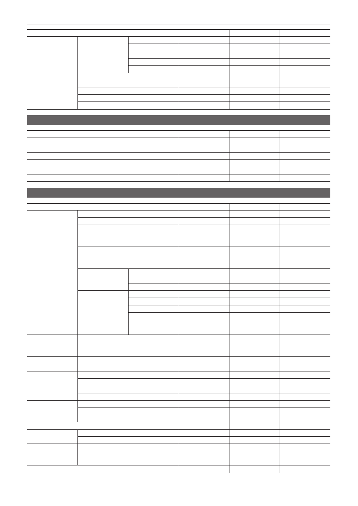
– 124 –
Chapter 4 Operation — Target items for scene le/setup le/initialization
Item SCENE SETUP INITIALIZE
[IP ADDRESS] —
l l
[SUBNET MASK] —
l l
[DEFAULT GATEWAY] —
l l
[PRIMARY DNS] —
l l
[SECONDARY DNS] —
l l
[INFORMATION] [STATUS] — — —
[UTILITY] [NETWORK INITIALIZE] — — —
[NET CHECKER] — — —
[EASY IP SETTING] — —
l
[EASY IP CAMERA TITLE] —
l l
[SYSTEM] menu
Item SCENE SETUP INITIALIZE
[FREQUENCY] —
l l
[FILE FORMAT] —
l l
[REC FORMAT] —
l l
[AUDIO SAMPLE RES.] —
l l
[SHOOTING MODE] —
l l
[COLOR SETTING] —
l l
[OTHERS] menu
Item SCENE SETUP INITIALIZE
[FILE] [SCENE FILE(SD CARD)] — — —
[SETUP FILE(SD CARD)] — — —
[SETUP FILE(MEMORY)] — — —
[CAC FILE(SD CARD)] — — —
[LENS FILE(SD CARD)] — — —
[LENS FILE(MEMORY)] — — —
[SLOT FOR LOAD/SAVE] —
l l
[BATTERY] [DC IN SOURCE] —
l l
[DC IN BATTERY] [FULL VOLT] —
l l
[NEAR END VOLT] —
l l
[END VOLT] —
l l
[ONBOARD BATTERY] [BATTERY SEL] —
l l
[FULL VOLT] —
l l
[NEAR END VOLT] —
l l
[END VOLT] —
l l
[NEAR END INFO] —
l l
[END INFO] —
l l
[GENLOCK] [GENLOCK] —
l l
[H PHASE COARSE] —
l l
[H PHASE FINE] —
l l
[COLOR BARS] [COLOR BARS TYPE] —
l l
[TEST TONE] —
l l
[LED] [REC TALLY] —
l l
[ACCESS LED] —
l l
[LAN LED] —
l l
[STREAMING LED] —
l l
[CLOCK] [CLOCK SETTING] — — —
[TIME ZONE] — — —
[DATE FORMAT] —
l l
[GPS] —
l l
[USB DEVICE] [CARD READER MODE] — — —
[SERVICE MODE] — — —
[INFORMATION] [VERSION] — — —
[OPERATION TIME] — — —
[UPDATE] — — —
[LANGUAGE] —
l l

– 125 –
Chapter 4 Operation — Target items for scene le/setup le/initialization
Item SCENE SETUP INITIALIZE
[MENU INITIALIZE] — — —
[OPTION] menu
Item SCENE SETUP INITIALIZE
[AREA SETTINGS] — — —
[BLACK SHADING ADJ.] — — —

This chapter describes the basic procedure for recording. This chapter also describes the special recording method.
Chapter 5 Shooting
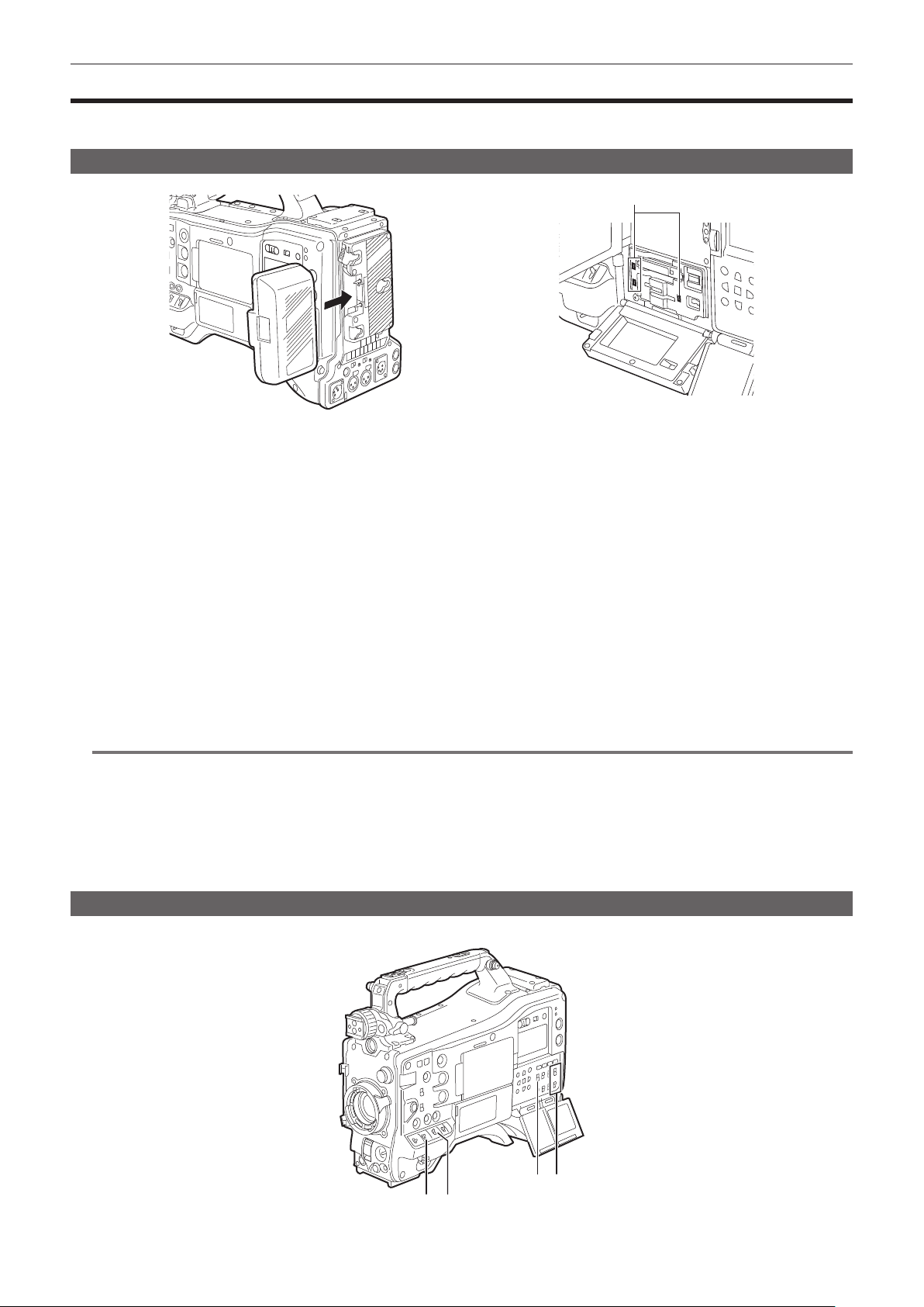
– 127 –
Chapter 5 Shooting — Basic procedures
Basic procedures
This section describes the basic procedures for shooting and recording. Before you actually start shooting, pre-inspect your system to ensure that it
works properly. (page 48)
Preparing power supply and inserting memory cards
Card access lamp
Fig. 1 Fig. 2
1
Insert a charged battery pack. (Fig. 1)
2
Set the power switch to < j > (ON), and make sure that five or more levels on the battery level display bar on the display window
are lit.
If less than ve levels of the battery level display bar are lit, be sure to check the battery settings. (page 109)
If the settings are correct, replace with a fully charged battery.
3
Insert a memory card, make sure that the card access lamp is illuminated in orange or green, and then close the slot cover. (Fig.
2)
When two microP2 cards or SD cards are inserted in the card slots 2 and 3, the card with the smaller slot number will be recorded to rst. However,
the memory card inserted later will be recorded after the memory card that was inserted rst.
f Example: When microP2 cards are inserted in two card slots
If microP2 cards are inserted into two slots, the cards are used in the order of card slot 2 → 3. However, if the microP2 card in the card slot 2 is
removed and then re-inserted, the cards will be used in the order of card slot 3 → 2.
The card slot number to be recorded to is held even if the camera is turned off. When the camera is next turned on, recording can be continued to
the memory card inserted in the same card slot as before the camera was turned off.
@
NOTE
t If a low battery charge level is indicated even after replacing with a fully charged battery, make sure that the battery has been set correctly.
(page 109)
t Specify the card slot to use on the menu in advance. It cannot record when a memory card is inserted in a card slot that is not set.
Select the memory card format or card slot to use according to the following methods.
- Set in the [RECORDING] menu → [REC MEDIA].
- Re-insert the card into the set card slot. (page 52)
t Displays the card slot number on the remaining memory card capacity display area of the viewnder when recording target card slot switches. For
details on indications in the viewnder, refer to “Conguration of status display on viewnder screen” (page 153).
Switch settings for shooting
After turning on the power and inserting a memory card, set the switches as follows.
a
c d
b

– 128 –
Chapter 5 Shooting — Basic procedures
a: <GAIN> switch
Normally, set this to <L> (0 dB). If it is too dark, set the gain to an appropriate value.
b: <OUTPUT>/<AUTO KNEE> switch
Set this switch to <CAM>/<ON>.
c: <TCG> switch
Set this switch to <F-RUN> or <R-RUN>.
d: <AUDIO SELECT CH1/3>/<AUDIO SELECT CH2/4> switch
Set this switch to <AUTO>.
Adjustments for shooting
For shooting, use the following steps.
1
Switch the <CC FILTER>/<ND FILTER> dial setting according to the light conditions.
For details on setting example of the <CC FILTER>/<ND FILTER> dial, refer to “Shooting and recording (Camera unit)” (page 25).
2
Operate the <WHITE BAL> switch.
r When white balance is already saved in memory
f Set the <WHITE BAL> switch to <A> or <B>.
r When neither white or black balance is saved in memory and there is no time to adjust the white balance:
f Set the <WHITE BAL> switch to <PRST>. The white balance matched to the lter is automatically adjusted according to the <CC FILTER>/<ND
FILTER> dial setting.
r When adjusting the white balance on the spot
f Select the lter matched to the lighting conditions. Set the <WHITE BAL> switch to <A> or <B>, shoot a white subject in the center of the screen,
and follow the steps below to adjust the white balance.
1) Press the <AUTO W/B BAL> switch towards the <AWB> side to adjust the white balance. (page 129)
2) Press the <AUTO W/B BAL> switch towards the <ABB> side to adjust the black balance. (page 131)
3) Press the <AUTO W/B BAL> switch towards the <AWB> side to re-adjust the white balance.
3
Point the camera at the subject and adjust the focus and zoom.
4
When using the electronic shutter, set the shutter mode and shutter speed. (page 132)
@
NOTE
t When highly bright subjects (e.g. sun or lighting) are shot, the periphery of the subject might be colored.
Normal recording
Press the <REC> button to start recording of video and audio on the memory card.
A data consisting of image and sound generated by a single shooting action, together with additional information, is called a “clip”.
1
Press the <REC> button to start recording.
The [REC] lamp in the viewnder is illuminated during recording.
2
Press the <REC> button again to stop.
The [REC] lamp in the viewnder goes out.
@
NOTE
t <REV (%)>/<STOP (()>/<FWD ())>/<PLAY/PAUSE (=/&)> buttons will not operate during recording.
t In the following cases, it may take time to complete writing to the memory card.
Pressing the <REC> button does not accept operations immediately.
- When short-burst recording is stopped
- When stopping recording immediately after recording to the second memory card
t The recording is started using the memory of the camera even if the recording is started right after the memory card is inserted or the power is turned
on. In such case, the recording cannot be stopped until the memory card is recognized. The warning is displayed as [REC PAUSE INVALID] at this
time.
t After pressing the <REC> button in Step
2, some time may be required until the recording stops.
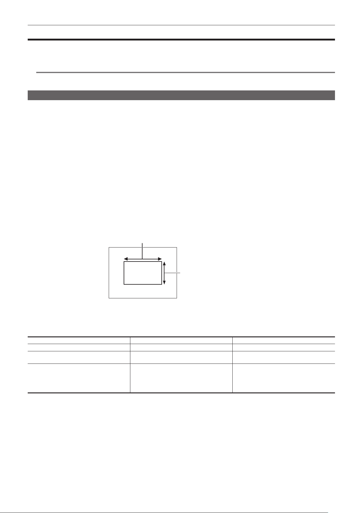
– 129 –
Chapter 5 Shooting — Adjusting the white and black balance
Adjusting the white and black balance
To obtain high-quality video at all times using the camera, the white and black balance must be adjusted according to conditions.
Adjust the AWB (white balance adjustment), ABB (black balance adjustment), and AWB (white balance adjustment) in order to obtain higher image
quality.
@
NOTE
t When white or black balance is adjusted while video is disrupted by the genlock, adjustment may not be performed correctly. Adjust white or black
balance again after video has returned to normal.
White balance adjustment
The white balance must be adjusted again when the lighting conditions change. Follow the steps below to adjust the white balance automatically.
r Storing in memory <A>
1
Set the <WHITE BAL> switch to <A>.
2
Set the <GAIN> and <OUTPUT>/<AUTO KNEE> switches.
3
Select the <CC FILTER>/<ND FILTER> dial setting according to the light conditions.
For details on setting example of the <CC FILTER>/<ND FILTER> dial, refer to “Shooting and recording (Camera unit)” (page 25).
4
Place the white pattern at a point where the light conditions match those for the light source for the subject, and zoom in on the
white pattern so that the white color appears in the screen.
5
Adjust the lens aperture.
6
Press the <AUTO W/B BAL> switch towards <AWB> side and then release it.
The switch returns to the central position and the white balance will be automatically adjusted.
r White pattern
f A white object (cloth or wall) near the subject may also be used for the white pattern.
f Required size of white pattern is as follows.
1/4 or more of the screen width
1/4 or more of the screen height
f Keep bright spotlights out of the screen.
f The white pattern must be placed at the center of the screen.
r Messages displayed in the viewnder and LCD monitor
f When the auto tracking white balance (ATW) function is operating, white balance cannot be adjusted.
Status Message Remark
During adjustment [AWB A ACTIVE]
Adjustment completed [AWB A OK 3200K]
f The adjusted value is automatically stored in the
specied memory (A or B).
If the color temperature of the subject is low or
higher than 15000 K
[AWB NG <COLOR TEMP LOW>]
[AWB NG <COLOR TEMP HIGH>]
f [AWB NG <COLOR TEMP LOW>] indicates
that the temperature is lower than the displayed
temperature. [AWB NG <COLOR TEMP HIGH>]
indicates that the temperature is higher than the
displayed color temperature.
r [COLOR TEMP Ach SETTING]/[COLOR TEMP Bch SETTING] setting
f The color hue can be changed after the white balance has been adjusted automatically, after setting each item in the [SCENE FILE] menu → [COLOR
TEMP Ach SETTING]/[COLOR TEMP Bch SETTING].
f Adjusting either one of [COLOR TEMP], [R GAIN], [B GAIN], and [G AXIS] changes the other three values.
f Performing the automatic white balance again resets [COLOR TEMP], [R GAIN], [B GAIN], and [G AXIS].
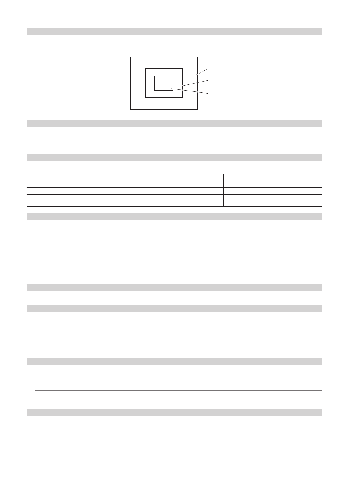
– 130 –
Chapter 5 Shooting — Adjusting the white and black balance
Detection range of white balance
The white balance detection range can be selected from [90%], [50%], and [25%] in the [CAMERA] menu → [WHITE BALANCE MODE] → [AWB
AREA]. The factory setting value is [25%].
90%
50%
25%
When having no time to adjust the white balance
Set the <WHITE BAL> switch to <PRST>.
f The value displayed as [VAR] is not always assured. Use it as a reference value.
f According the shooting conditions, turn the <CC FILTER>/<ND FILTER> dial and set the lter.
When the white balance has not been automatically adjusted
When the white balance has not been successfully adjusted, an error message is displayed on the viewnder screen and LCD monitor displays.
Error message Meaning Remedy
[AWB NG <LOW LIGHT>] There is insufcient light. Increase the amount of light or increase gain.
[AWB NG <LEVEL OVER>] There is too much light. Decrease the amount of light or decrease gain.
[AWB NG <COLOR TEMP LOW>] or [AWB NG
<COLOR TEMP HIGH>]
The color temperature is too high, or too low. Use the appropriate lter or light source.
White balance memory
Values stored to memory are saved until white balance is adjusted again even if the camera is turned off. There are two white balance memories, A and
B.
When set to the [CAMERA] menu → [WHITE BALANCE MODE] → [FILTER INH] → [ON] (initial setting), memory on each of <A> and <B> is limited to
one, respectively. In this case, content in memory is not interlocked with the lter.
When [FILTER INH] is set to [OFF], the adjustment values of each lter can be automatically stored to memory corresponding to the <WHITE BAL>
switch setting (<A> or <B>).
The camera has four built-in lters so a total of eight (4×2) adjustment values can be stored to memory.
When the super gain function is enabled, the <AUTO W/B BAL> switch does not function and the message ([AWB UNABLE]/[S.GAIN MODE]) is
displayed.
Viewnder and LCD monitor screen displays relating to white balance
For details, refer to “Screen display during shooting” (page 154).
Setting the auto tracking white balance function (ATW)
The camera is equipped with the Auto Tracking White Balance (ATW) function that automatically tracks the white balance of images according to the
lighting conditions.
Assigns the auto tracking white balance function to the <A>/<B>/<PRST> of <WHITE BAL> switch. Set in the [CAMERA] menu → [WHITE BALANCE
MODE] → [ATW].
Note that if the auto tracking white balance function is assigned to the USER button, the function follows the operation of the USER button.
For details, refer to “Assigning function to the USER buttons” (page 136).
Canceling the auto tracking white balance
Press the USER button which the auto tracking white balance function is assigned again, or switch the <WHITE BAL> switch. Note that if the auto
tracking white balance function is set to the <WHITE BAL> switch, the function cannot be canceled with the USER button.
@
NOTE
t Auto tracking white balance function does not guarantee 100% accuracy for the white balance. Note that the tracking performance relative to changes
in ambient lighting and white balance performance of the auto tracking white balance function has been given a certain degree of latitude.
Manual setting of color temperature
White balance can be adjusted manually according to the color temperature setting. The manual color temperature setting can be set individually to
<PRST>, <A> and <B> of the <WHITE BAL> switch.
Sets the color temperature to be assigned to <PRST> in the [CAMERA] menu → [WHITE BALANCE MODE] → [W.BAL PRESET]/[W.BAL VAR].
[W.BAL PRESET]: This can be selected from [3200K], [5600K], and [VAR].
[W.BAL VAR]: Can be set to [2000K] to [15000K] (when the <CC FILTER> dial is <A>), [2380K] to [>15000K] (when the <CC FILTER> dial is <B>),
[2730K] to [>15000K] (when the <CC FILTER> dial is <C>), and [2890K] to [>15000K] (when the <CC FILTER> dial is <D>).
Sets the color temperature to be assigned to <A>/<B> in each item in the [SCENE FILE] menu → [COLOR TEMP Ach SETTING]/[COLOR TEMP Bch
SETTING].

– 131 –
Chapter 5 Shooting — Adjusting the white and black balance
@
NOTE
t Even if color temperature is set manually, the color temperature adjusted automatically is recorded to the setting of the <WHITE BAL> switch at
that time if white balance is automatically adjusted. The value of the color temperature also changed when the position of the <CC FILTER> dial is
switched.
Black balance adjustment
Black balance must be adjusted in the following instances:
f When the camera is used for the rst time
f When used after a long period of time without use
f When the ambient temperature has changed considerably
f When super gain is set with the USER button
f When the [CAMERA] menu → [USER SW] → [USER1] to [USER5] → [DS.GAIN] is assigned
f When the digital super gain assignment is changed in the [CAMERA] menu → [USER SW GAIN] → [DS.GAIN]
f When toggling items in the [SYSTEM] menu → [REC FORMAT].
To shoot optimum video, we recommend adjusting the black balance immediately before shooting.
Before adjusting the black balance, prepare the conditions for adjusting the white balance.
1
Press the <AUTO W/B BAL> switch towards <ABB> side and then release it.
The switch returns to the central position and the black balance will be automatically adjusted.
Adjustment is completed in several seconds.
r Messages displayed in the viewnder and LCD monitor
Status Message Remark
During adjustment [ABB ACTIVE] —
Adjustment completed [ABB OK]
f The adjusted value is automatically stored in
memory.
@
NOTE
t Make sure that the lens connector is connected and that the lens aperture is in the close mode.
t During black balance adjustment, the aperture is set to automatically shut out light.
t During recording, black balance cannot be adjusted.
t Video is not recorded to the memory card even if the <REC> button is pressed while executing the automatic black balance.
t The gain switching circuit is automatically switched during black balance adjustment. Flicker or noise sometimes appears on the viewnder screen and
LCD monitor. This is not a malfunction.
t Even after automatic black balance has ended, if black shading is a cause for concern, select the [CAMERA] menu → [BLACK SHADING] →
[DETECTION], and adjust black shading. Alternatively, set to the [CAMERA] menu → [SW MODE] → [SHD,ABB SW CTL] → [ON] and hold down
the <AUTO W/B BAL> switch for two seconds or more to adjust black shading. [BLACK SHADING READY] will be displayed in the viewnder, and
black shading can be automatically adjusted after the automatic black balance operation. While black shading is being adjusted, [BLACK SHADING
ACTIVE] will be displayed in the viewnder. After this, be sure to close down the lens aperture until [BLACK SHADING OK] is displayed in the
viewnder.
t When black balance is being automatically adjusted (when [ABB ACTIVE] is displayed in the viewnder), adjustment is canceled by pushing the
<AUTO W/B BAL> switch towards <ABB> side again. The adjustment values will return to the values before automatic adjustment was performed.
Black balance memory
Values stored to memory are saved even if the camera is turned off.
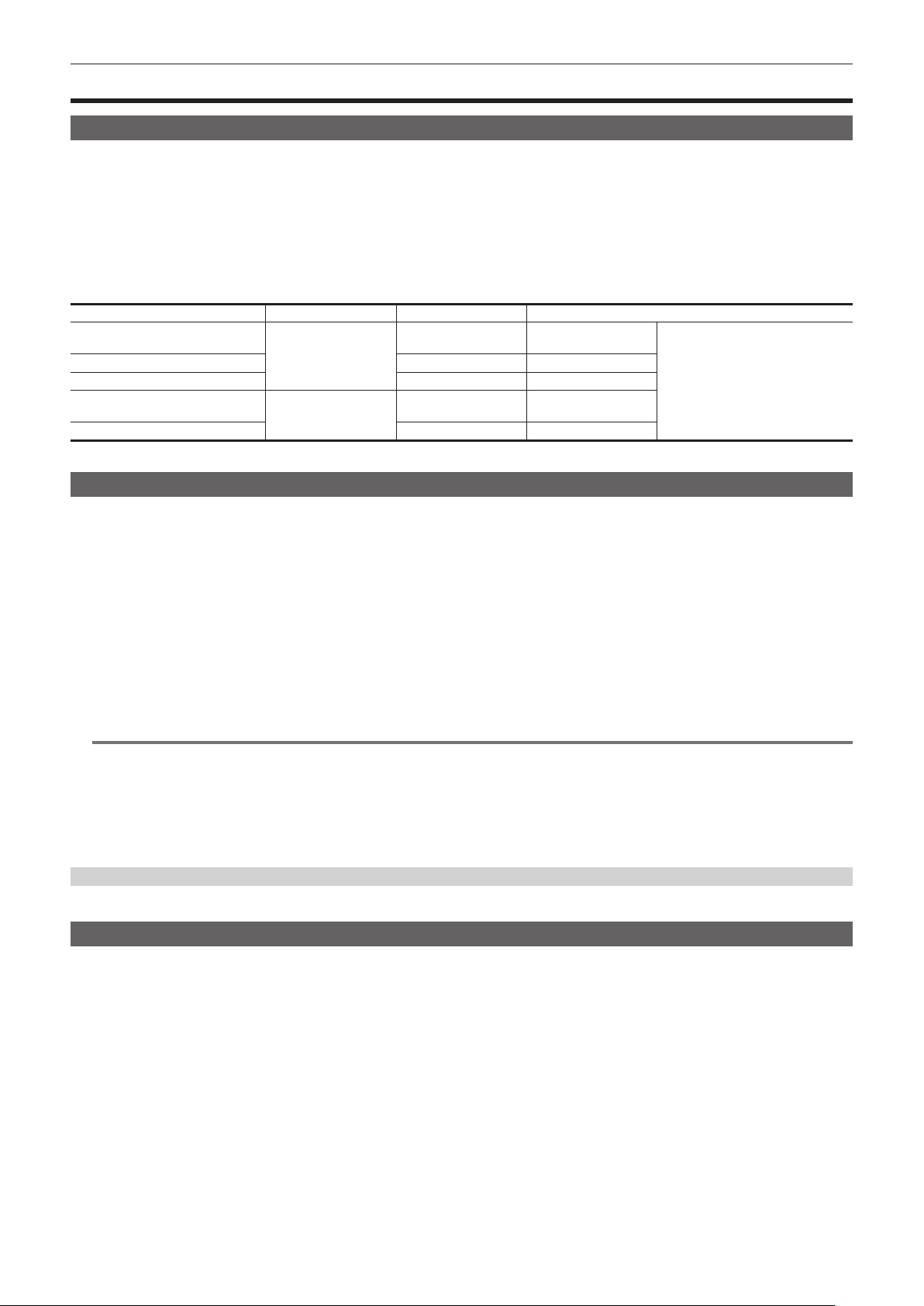
– 132 –
Chapter 5 Shooting — Setting the electronic shutter
Setting the electronic shutter
Shutter mode
The shutter modes available on the camera’s electronic shutter and shutter speeds that can be selected are as follows.
f Using a xed shutter speed
-When removing icker caused by lighting
-When shooting fast-moving subjects clearly
f Using the synchro scan mode
-When shooting eliminating stripe patterns in the horizontal direction while shooting on the monitor screen
-When shooting moving subjects with special effects
f Using the half shutter speed
-When shooting with special effects such as lms
[REC FORMAT]* Shutter speed Half shutter speed Variable range of synchro scan mode
59.94p
59.94i
[1/100], [1/120], [1/250],
[1/500], [1/1000],
[1/2000], [HALF]
1/120 1/60.0 to 1/7200
3.0 deg to 360 deg
(in 0.5 deg steps)
29.97p 1/60 1/30.0 to 1/7200
23.98p 1/48 1/24.0 to 1/7200
50.00p
50.00i
[1/60], [1/120], [1/250],
[1/500], [1/1000],
[1/2000], [HALF]
1/100 1/50.0 to 1/7200
25.00p 1/50 1/25.0 to 1/7200
* [REC FORMAT] indicates only frame rate. For example, [1080-59.94i/AVC-G50] is 59.94i, and [2160-29.97p/420LongGOP 100M] is 29.97p.
Setting the shutter mode/shutter speed
Switch the <SHUTTER> switch to set the shutter speed in the shutter mode.
The shutter speed in the synchro scan mode can be changed by the <SYNCHRO SCAN> button on the side.
The shutter speed selection range can be restricted or use of the synchro scan mode can be selected beforehand in each item in the [CAMERA] menu
→ [SHUTTER SPEED].
Once selected, the shutter speed is saved even after the camera is turned off.
1
Press the <SHUTTER> switch positioned at <OFF> towards <ON>.
[POSITION1] is enabled.
2
Press the <SHUTTER> switch from <ON> towards <SEL>, and repeat this operation until the desired shutter mode or shutter
speed is displayed on the viewfinder screen.
f If all shutter modes and shutter speeds are available, the display changes in the following order.
[POSITION1], [POSITION2], [POSITION3], [POSITION4], [POSITION5], [POSITION6], [SYNCHRO SCAN]
@
NOTE
t Whichever shutter mode the electronic shutter is used in, the higher the shutter speed, the lower the sensitivity of the camera becomes.
t When the aperture is in the automatic mode, it will increasingly open and the depth of focus will become shallower as the shutter speed is increased.
t Under lighting conditions using uorescent lighting or other discharge tube, horizontal stripes might appear on screen. If this happens, this can be
improved by adjusting the shutter speed.
t A subject that quickly crosses the camera may appear distorted when shot. This is due to the method applied for reading the signals from the pickup
device (MOS sensor), and is not a malfunction.
t Shutter mode is disabled while the digital super gain function is active.
Viewnder screen display for shutter
For details, refer to “Display of the viewnder status” (page 153).
Setting synchro scan mode
Follow the steps below to operate.
1
Press the <SHUTTER> switch from the <ON> side towards the <SEL> side to set the camera to the synchro scan mode.
2
Press the <SYNCHRO SCAN> button to adjust the shutter speed.
The shutter speed display in the synchro scan mode can be switched between seconds and angle in the [SCENE FILE] menu → [SYNC SCAN
TYPE].
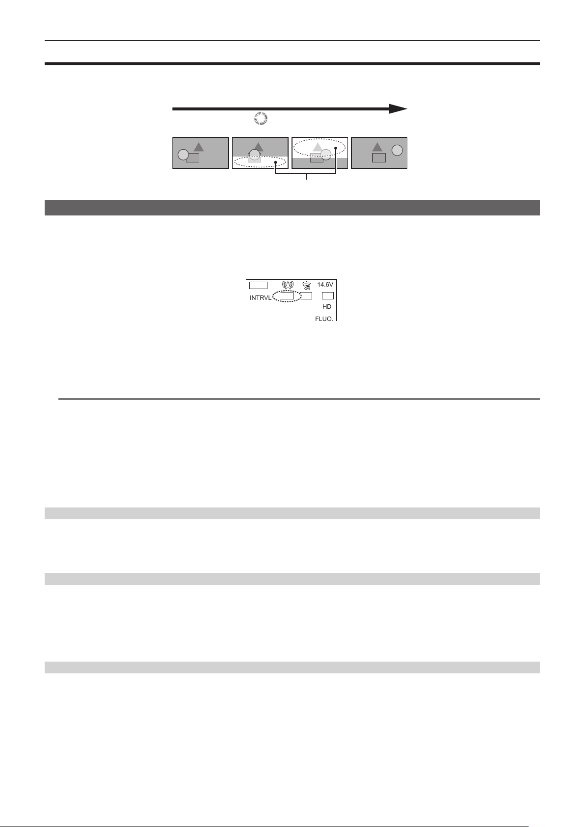
– 133 –
Chapter 5 Shooting — Flash band compensation (FBC) function
Flash band compensation (FBC) function
The camera is equipped with a function for compensating and reducing band-like interference (called “ash band”) that occurs due to the MOS pickup
device when shooting in environments where ash strobe light such as that from still cameras is present.
Change over time
Shot image
(FBC OFF)
Flash firing
Flash band
Setting the ash band compensation function
Assign the ash band compensation function to the USER buttons.
By pressing the USER buttons that are assigned with the ash band compensation function, the function turns on, and ash strobe from a still camera,
etc. can be detected and compensated.
For details, refer to “Assigning function to the USER buttons” (page 136).
When the ash band compensation function is enabled, [FBC1] or [FBC2] is displayed on the STATUS screen.
INTRVL
HD
FLUO.
14.6V
FBC1
RELAY
HDR CAC
In [FBC1] mode, color may tint at the border between the bright and dark part of the ash band image and at the horizontal border of the ash band
compensation image.
The color tint of the horizontal line may be reduced in [FBC2] mode.
Mode can be switched to [FBC2] mode by pressing the USER button for three seconds or more.
([FBC2] will be displayed on the STATUS screen.)
@
NOTE
t When the ash strobe lights, the following phenomena may occur. These are due to the ash band compensation function and are not malfunctions.
- Moving subjects look as if they have stopped suddenly.
- The resolution when the ash strobe light drops.
- Horizontal lines appear in the video when the ash strobe lights.
(There may be color tint on the horizontal line.)
- Flash bands may appear only in images shot at the time the ash is red.
(There may be color tint on the horizontal line of the ash band.)
t [FBC1] mode functions mostly same as the [FBC] mode (displayed as [FBC] on the STATUS screen) in the camera with rmware below Ver.3.00.
t When using [FBC2] mode, update the rmware of the camera to Ver.3.00 or above and then adjust the setting in the [OPTION] menu → [BLACK
SHADING ADJ.]. For information, refer to the download page of the rmware.
Using the ash band compensation function
The ash band compensation function is activated when there are large changes in brightness at the bottom of the screen regardless of whether there
is ash strobe light. The ash band compensation function may be activated depending on the shooting environment such as where a bright window has
zoomed in and then out. So, we recommend use of this function in shooting environments where ash strobe lighting is anticipated.
Even if ash strobe lighting occurs, sufcient ash band compensation function effect may not be obtained in some shooting environments.
Flash band compensation function operation conditions
f The ash band compensation function can be used under the conditions that electronic shutter and digital super gain functions are all not operating.
f Even if the ash band compensation function is enabled, the ash band compensation function is temporarily disabled if the camera is changed to a
mode where the ash band compensation function cannot be used.
When using the function again, return to a mode that can use the ash band compensation function. Flash band compensation function will be
automatically enabled.
The ash band compensation function is disabled once the power is turned off.
Operation of the ash band compensation function ([FBC1]/[FBC2] mode)
f To switch to [FBC1] mode or [FBC2] mode, operate the USER button as follows:
-Switching to [FBC1] mode: Press the USER button once to switch to [FBC1] mode. Pressing the USER button once in [FBC1] mode will turn off the
[FBC1] mode.
-Switching to [FBC2] mode: Press the USER button for three seconds or more to switch to [FBC2] mode. Pressing the USER button for three
seconds or more in [FBC2] mode will turn off the [FBC2] mode.
Pressing the USER button for three seconds or more in [FBC1] mode does not switch to [FBC2] mode. Pressing the USER button once in [FBC2]
mode does not switch to [FBC1] mode.
f Distortions or black image may be displayed while switching to [FBC2] mode. It may take approximately four to ve seconds until a stable image is
displayed.

– 134 –
Chapter 5 Shooting — Flash band compensation (FBC) function
f Switching to [FBC2] mode is enabled only when the [SYSTEM] menu → [REC FORMAT] is set to one of the following:
[2160-59.94p], [1080-59.94p], [1080-59.94i], [720-59.94p], [2160-50.00p], [1080-50.00p], [1080-50.00i], [720-50.00p]
(When set to anything other than the above, the camera will not switch to [FBC2] mode even when following the operation to switch to [FBC2] mode)
f Electronic shutter does not operate in [FBC2] mode (electronic shutter is always off).
f If the power is turned off in [FBC1] mode (or [FBC2] mode), [FBC1] mode (or [FBC2] mode) will be turned off when the power is turned back on.
f After switching to [FBC2] mode, perform auto black balance (ABB) with the <AUTO W/B BAL> switch.
f In [FBC2] mode, ash band image tend to appear more compared to [FBC1] mode. When shooting a fast moving subject or when moving the camera
rapidly during pan shooting, the subject may be shot slightly inclined (it is recommended to be used when the subject is not making large movement).

– 135 –
Chapter 5 Shooting — Setting high dynamic range (HDR)
Setting high dynamic range (HDR)
Recording in high dynamic range (HDR)
1
Select the [SCENE FILE] menu → [GAMMA MODE SEL] → [HLG].
The output will be as follows.
<SDI OUT1> terminal: Outputs in high dynamic range (HDR) or standard dynamic range (SDR) according to the setting of the [VIDEO OUT/LCD/
VF] menu → [SDI OUT1] → [SDI OUT HDR].
<SDI OUT2> terminal: Outputs in high dynamic range (HDR) or standard dynamic range (SDR) according to the setting of the [VIDEO OUT/LCD/
VF] menu → [SDI OUT2] → [SDI OUT HDR].
<HDMI> terminal: When set to the [VIDEO OUT/LCD/VF] menu → [HDMI OUT] → [SIGNAL SEL] → [SDI OUT1(2160p)], outputs according to
the setting of the [VIDEO OUT/LCD/VF] menu → [SDI OUT1] → [SDI OUT HDR]. When set to [SDI OUT2], outputs according to the setting of the
[VIDEO OUT/LCD/VF] menu → [SDI OUT2] → [SDI OUT HDR].
Viewnder, LCD monitor: Outputs according to the setting of the [VIDEO OUT/LCD/VF] menu → [LCD/VF HDR]. HDR or SDR can be selected
when recording in HDR.
@
NOTE
t High Dynamic Range (HDR) recording is not possible when the [SYSTEM] menu → [COLOR SETTING] → [V-Log] is set.
Playing back the signal recorded in high dynamic range (HDR)
When set to the [SCENE FILE] menu → [GAMMA MODE SEL] → [HLG], detects the recorded information and sets as follows.
r When recorded information is in high dynamic range
<SDI OUT1> terminal: Outputs in high dynamic range (HDR) or standard dynamic range (SDR) according to the setting of the [VIDEO OUT/LCD/VF]
menu → [SDI OUT1] → [SDI OUT HDR].
<SDI OUT2> terminal: Outputs in high dynamic range (HDR) or standard dynamic range (SDR) according to the setting of the [VIDEO OUT/LCD/VF]
menu → [SDI OUT2] → [SDI OUT HDR].
<HDMI> terminal: When set to the [VIDEO OUT/LCD/VF] menu → [HDMI OUT] → [SIGNAL SEL] → [SDI OUT1(2160p)], outputs according to the
setting of the [VIDEO OUT/LCD/VF] menu → [SDI OUT1] → [SDI OUT HDR]. When set to [SDI OUT2], outputs according to the setting of the [VIDEO
OUT/LCD/VF] menu → [SDI OUT2] → [SDI OUT HDR].
Viewnder, LCD monitor: Outputs according to the setting of the [VIDEO OUT/LCD/VF] menu → [LCD/VF HDR]. HDR or SDR can be selected when
recording in HDR.
r When recorded information is not in high dynamic range or there is no recorded information
<SDI OUT1>/<SDI OUT2>/<HDMI> terminal, view nder, LCD monitor: Outputs the recorded video as is.
Following settings will be disabled: the [VIDEO OUT/LCD/VF] menu → [SDI OUT1]/[SDI OUT2] → [SDI OUT HDR], the [VIDEO OUT/LCD/VF] menu →
[LCD/VF HDR].
@
NOTE
t For clips recorded with high dynamic range (hybrid log gamma), [HLG] is displayed for [GAMMA] item in detailed information about the clip displayed
in the [THUMBNAIL] menu → [CLIP] → [INFORMATION].
t Recorded video will be output as is regardless of recorded information when anything other than the [SCENE FILE] menu → [GAMMA MODE SEL] →
[HLG] is selected.
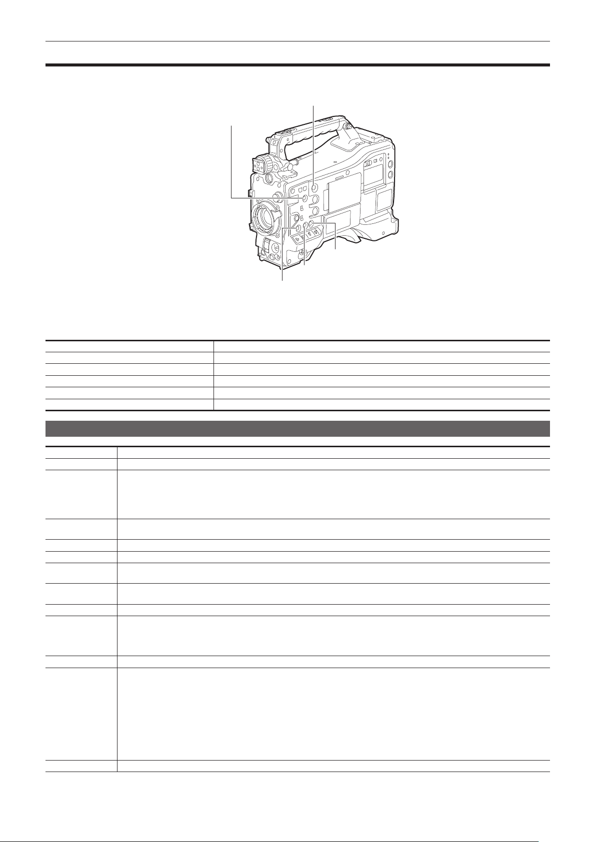
– 136 –
Chapter 5 Shooting — Assigning function to the USER buttons
Assigning function to the USER buttons
Selected function can be assigned to the USER buttons.
The camera has ve USER buttons.
<USER 3> button
<USER 5> button
<USER 4> button
<USER 2> button
<USER 1> button
1
Select the function to assign to each in the [CAMERA] menu → [USER SW] → [USER1] to [USER5].
r Factory settings
USER button Function
<USER 1> button [FOCUS ASSIST]
<USER 2> button [S.GAIN]
<USER 3> button [DS.GAIN]
<USER 4> button [Y GET]
<USER 5> button [WFM]
Selectable functions
Item name Description
[INHIBIT] Disables assignment of functions.
[DRS]
Assigns the dynamic range stretcher function. This function expands the dynamic range by compressing the image level in high-luminosity
areas and stretching the image level in low-luminosity areas.
The compression level can be varied in the [SCENE FILE] menu → [DRS EFFECT DEPTH].
f A slight difference in coloring might occur by enabling/disabling the dynamic range stretcher function.
f When the dynamic range stretcher function is enabled, the knee function or the black gamma function are not activated.
[FBC]*
Enables/disables the ash band compensation function.
Switches to [FBC1] mode when pressed once. Switches to [FBC2] mode when pressed for three seconds or more.
[S.GAIN]* Assigns the super gain function. Automatic white balance does not function while the super gain function is enabled.
[ATW]* Assigns the auto tracking white balance function.
[ATW LOCK]*
Fixes the white balance value when pressing this item while the auto tracking white balance function is activated. Resumes the auto
tracking white balance function when pressing again.
[Y GET]*
Assigns the function for displaying the luminance level of the image at the position indicated by the square marker displayed near the
center.
[D.ZOOM]* Assigns the digital zoom function. Zooms in on the eld angle by 2x, 3x and 4x vertically and horizontally.
[DS.GAIN]*
Assigns the digital super gain function.
f The digital super gain function is activated only during shooting in 59.94p, 59.94i, 50p, and 50i. While the function is activated, the
shutter becomes [OFF].
f Video at the instant that the digital super gain function is enabled/disabled, becomes discontinuous.
[S.IRIS]* Assigns the super iris function. This is enabled when performing backlight compensation.
[I.OVR]*
Assigns the iris override function. To change the target value in auto iris mode, set to this mode and press the jog dial button. Turn the
jog dial button to the left or right to change the target value. [+]/[++]/[−]/[−−] is displayed on the iris override display area on the viewnder
screen.
Stop turning the jog dial button at the position to change the target value and press the jog dial button to apply the new target value
setting. The reference value is returned when this mode is canceled or the power is turned off.
[+]: Opens aperture by about 0.5.
[++]: Opens aperture by about 1.
[−]: Closes aperture by about 0.5.
[−−]: Closes aperture by about 1.
No display: Reference value.
[S.BLK]* Assigns the super black function. This is the function for lowering the black level to the pedestal level or below.
– 137 –
Chapter 5 Shooting — Assigning function to the USER buttons
Item name Description
[B.GAMMA]*
Assigns the black gamma function. This function enhances the black tones.
Regardless of the value set by selecting the [SCENE FILE] menu → [LOW SETTING]/[MID SETTING]/[HIGH SETTING] → [BLACK
GAMMA], [BLACK GAMMA]: [6] and [B.GAMMA RANGE]: [3] are set.
[FOCUS ASSIST]*
Displays/hides the focus assist display.
Select the type of display in the [VIDEO OUT/LCD/VF] menu → [FOCUS ASSIST] → [FOCUS ASSIST SELECT].
[C.TEMP]*
Assigns the function for switching to the mode for changing the color temperature by the jog dial button. This is effective for intentionally
varying the color temperature after white balance has been performed. To change the color temperature, press the USER button assigned
with this function, and then press the jog dial button. The color temperature indicator in the viewnder screen ashes in reverse to indicate
that the mode is entered for changing the color temperature. While the indicator is ashing, turn the jog dial button to change the color
temperature. At this time, the setting value of the position (<PRST>/<A>/<B>) where the <WHITE BAL> switch is currently set is also
changed.
[ADAPTIVE MATRIX] Enables/disables the function to control the linear matrix in accordance with the shooting condition.
[PRE REC] Assigns the function for enabling/disabling the pre-recording.
[REC CHECK] Assigns the function to automatically play back the last approximately three seconds of the previously shot clip.
[DEL LAST CLIP] Assigns the function to delete the clip last shot.
[SLOT SEL] Assigns the function for switching the card slot to record to when memory cards are inserted to card slot 2 and card slot 3.
[REC SW] Assigns the function of the <REC> button.
[WFM]*
Assigns the function for displaying the waveform or vector in the viewnder and LCD monitor. Select the waveform display in the [VIDEO
OUT/LCD/VF] menu → [EI ASSIST] → [WFM MODE].
[LCD/VF HDR]
Assigns the function that switches output of the viewnder and LCD monitor to high dynamic range/standard dynamic range.
Enabled only when set to the [SCENE FILE] menu → [GAMMA MODE SEL] → [HLG].
[LCD/VF V-Log]
Assigns the function that switches output of the viewnder and LCD monitor to V-Log/V-709.
Enabled only when the [SYSTEM] menu → [COLOR SETTING] → [V-Log] is set.
[LCD/VF DETAIL] Assigns function to adjust the intensity for the contour of the video in the viewnder or LCD monitor to make it easier to focus.
[VF COLOR]
Assigns the function for switching the viewnder screen to color display/monochrome display.
This is interlocked with the setting value in the [VIDEO OUT/LCD/VF] menu → [VF COLOR].
[INDICATOR SW] Assigns the function for enabling/disabling the status display.
[LOAD SETUP FILE] Assigns the function to display the list of setup les saved in the SD card. This does not function in the thumbnail screen.
[LCD BACKLIGHT]
Assigns the function for switching the brightness of the LCD monitor.
Every time the USER button is pressed, it is toggled in the order of [−1], [0], [1], and [2].
[CARD READER
MODE]*
Assigns the function for enabling/disabling the card reader mode function (USB mass storage function).
[STREAMING
START]*
Assigns the function for starting or stopping streaming from the camera.
This is interlocked with the setting value in the [NETWORK] menu → [STREAMING] → [START].
[SHOT MARK] Assigns the shot mark function.
* The function also turns off when the camera is turned off.
Note, however, that the [C.TEMP] color temperature is held after it is altered.
[USER SW GAIN] switching setting
In addition to the standard gain that can be set to <L>/<M>/<H> of the <GAIN> switch, [S.GAIN] (super gain) mode for increasing analog gain to 30 dB
or more and [DS.GAIN] (digital super gain) mode for incrementally increasing gain using progressive drive can also be used in this camera.
For selection of this function, set the gains to be used in [S.GAIN] and [DS.GAIN] respectively in advance. Each item can be selected in the [CAMERA]
menu → [USER SW GAIN].
When [S.GAIN] and [DS.GAIN] are assigned to one of the USER buttons, gain can be increased by a combination with assigned USER buttons.
When increasing gain without an increase in noise Use the digital super gain function.
When increasing regular analog gain
(Noise increases)
Use only the super gain function.
The precision of auto iris, white balance and black balance is affected due to increased noise.
When using as a super high-sensitivity mode Use a combination of the super gain and digital super gain functions. Note, however, that
residual images will stand out more with moving subjects the greater the value for increasing
gain by digital super gain is set. Pay sufcient care when using this combination of functions.
For moving subjects, use [DS.GAIN] at [12dB] or below.
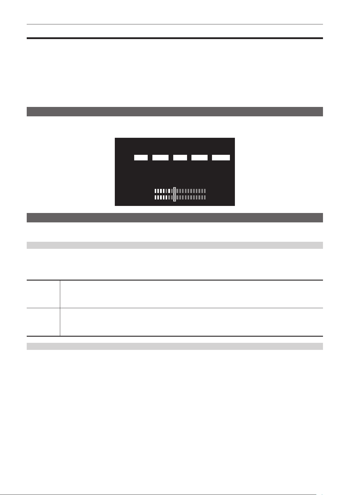
– 138 –
Chapter 5 Shooting — Selecting audio input signal and adjusting recording level
Selecting audio input signal and adjusting recording level
The camera supports independent 4-channel sound recording in all recording formats.
When the <AUDIO SELECT CH1/3>/<AUDIO SELECT CH2/4> switch is set to <AUTO>, the recording level of audio channels 1 and 2 (audio channels
3 and 4 according to the [AUDIO] menu → [REC CH SETTINGS] → [VOL. SELECT]) is automatically adjusted. The recording level can also be
manually adjusted by the <AUDIO LEVEL CH1/3>/<AUDIO LEVEL CH2/4> dials or <F.AUDIO LEVEL> dial when the switch is set to <MANU>.
Whether to adjust the recording level of audio channels 3 and 4 (audio channels 1 and 2 according to the [AUDIO] menu → [REC CH SETTINGS] →
[VOL. SELECT]) automatically or manually can be selected in the [AUDIO] menu → [REC CH SETTINGS] → [CH1 LEVEL] to [CH4 LEVEL] (adjusted
by the [AUDIO] menu → [REC CH SETTINGS] → [CH1 LEVEL CONTROL] to [CH4 LEVEL CONTROL]).
f On the camera, whether to adjust the audio level of audio channels 1 and 2 or audio channels 3 and 4 can be selected by the <AUDIO LEVEL
CH1/3>/<AUDIO LEVEL CH2/4> dial.
As the factory setting, the recording level of audio channels 1 and 2 is set to be adjusted by the <AUDIO LEVEL CH1/3>/<AUDIO LEVEL CH2/4> dial.
Selecting audio input signals
Selects the audio signal to input to the audio channel 1 to 4 by <AUDIO IN CH1> to <AUDIO IN CH4> switch.
The audio input selection status can be checked on the AUDIO screen of the mode check display.
---
---
---
---
---
---
-- --
:
:
:
:
:
:
CH1
CH2
CH1
A.IN F.VOL.LEVEL LIMITER LOWCUT
MIC POWER(MENU)
VOL. SELECT
ON(FRONT), OFF(REAR)
CH1/2
AUDIO
CH2
CH3
CH4
FRONT
FRONT
REAR
REAR
AUTO
AUTO
AUTO
AUTO
OFF
OFF
OFF
OFF
OFF
OFF
Adjusting recording level
Adjustment method of the recording level can be selected from manually adjusting by the <AUDIO LEVEL CH1/3>/<AUDIO LEVEL CH2/4> dial,
adjusting by menu item, or automatic adjustment in this camera.
Selecting recording level adjustment method
Assign two audio channels to the <AUDIO LEVEL CH1/3>/<AUDIO LEVEL CH2/4> dial in the [AUDIO] menu → [REC CH SETTINGS] → [VOL.
SELECT].
Two audio channels that are not assigned will be automatically adjusted, or adjust by menu item. [CH1/2] is assigned to the <AUDIO LEVEL
CH1/3>/<AUDIO LEVEL CH2/4> dial in the factory setting.
[CH1/2] Assigns the <AUDIO LEVEL CH1/3>/<AUDIO LEVEL CH2/4> dial to audio channels 1 and 2.
The <AUDIO SELECT CH1/3>/<AUDIO SELECT CH2/4> switches are also enabled for channels 1 and 2.
The audio channel 3 and 4 are automatically adjusted. Automatic adjustment will be disabled when the [AUDIO] menu → [REC CH
SETTINGS] → [CH3 LEVEL]/[CH4 LEVEL] → [MANUAL] is set.
Recording level can also be adjusted by [CH3 LEVEL CONTROL]/[CH4 LEVEL CONTROL].
[CH3/4] Assigns the <AUDIO LEVEL CH1/3>/<AUDIO LEVEL CH2/4> dial to audio channels 3 and 4.
The <AUDIO SELECT CH1/3>/<AUDIO SELECT CH2/4> switches are also enabled for audio channels 3 and 4.
Audio channels 1 and 2 will be automatically adjusted. Automatic adjustment will be disabled when the [AUDIO] menu → [REC CH SETTINGS]
→ [CH1 LEVEL]/[CH2 LEVEL] → [MANUAL] is set.
Recording level can also be adjusted by [CH2 LEVEL CONTROL]/[CH1 LEVEL CONTROL].
When the <AUDIO LEVEL CH1/3>/<AUDIO LEVEL CH2/4> dial is assigned to [CH1/2]
r Selecting recording level adjustment method for audio channels 1 and 2
For the recording level adjustment method of audio channels 1 and 2, select <AUTO> (automatic adjustment) or <MANU> (manual adjustment by the
<AUDIO LEVEL CH1/3>/<AUDIO LEVEL CH2/4> dial) by the <AUDIO SELECT CH1/3>/<AUDIO SELECT CH2/4> switch.
When <MANU> is selected, the recording level of audio channels 1 and 2 is adjusted by the <AUDIO LEVEL CH1/3>/<AUDIO LEVEL CH2/4> dial.
r Adjustment by the <AUDIO LEVEL CH1/3>/<AUDIO LEVEL CH2/4> dial
Adjust the <AUDIO LEVEL CH1/3>/<AUDIO LEVEL CH2/4> dial while viewing the audio channel level meter in the display window or the audio level
meter in the LCD monitor. When exceeding 0 dB, the topmost bar displays three segments to indicate that the recording level is too high. Adjust so it
does not exceed 0 dB.
r Adjustment by the <F.AUDIO LEVEL> dial
When operating the camera alone, using the <F.AUDIO LEVEL> dial to adjust the recording level is recommended. Select the audio channel to be
adjusted in advance, and while viewing the audio level meter of the viewnder screen, adjust the recording level with the <F.AUDIO LEVEL> dial so that
the recording level does not become too high.
When adjusting the recording level with the <F.AUDIO LEVEL> dial, enable/disable the <F.AUDIO LEVEL> dial by the setting of the <AUDIO IN
CH1>/<AUDIO IN CH2> switch in the [AUDIO] menu → [REC CH SETTINGS] → [FRONT VOL. CH1]/[FRONT VOL. CH2].
[OFF]: Disabled
[FRONT]: Enabled when <FRONT> is selected for the input signal
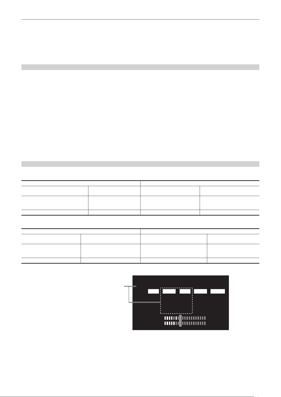
– 139 –
Chapter 5 Shooting — Selecting audio input signal and adjusting recording level
[W.L.]: Enabled when <W.L.> is selected for the input signal
[REAR]: Enabled when <REAR> is selected for the input signal
[ALL]: Enabled for all input signals
r Adjusting recording level of audio channels 3 and 4
Automatic adjustment will be enabled when the [AUDIO] menu → [REC CH SETTINGS] → [CH3 LEVEL]/[CH4 LEVEL] → [AUTO] is set. When
these items are set to [MANUAL], automatic adjustment stops functioning, and the recording level can be adjusted in the [AUDIO] menu → [REC CH
SETTINGS] → [CH3 LEVEL CONTROL]/[CH4 LEVEL CONTROL].
When the <AUDIO LEVEL CH1/3>/<AUDIO LEVEL CH2/4> dial is assigned to [CH3/4]
r Selecting recording level adjustment method for audio channels 3 and 4
For the level adjustment method of audio channels 3 and 4, select <AUTO> (automatic adjustment) or <MANU> (manual adjustment by the <AUDIO
LEVEL CH1/3>/<AUDIO LEVEL CH2/4> dial) with the <AUDIO SELECT CH1/3>/<AUDIO SELECT CH2/4> switch.
When <MANU> is selected, the recording level of audio channels 3 and 4 is adjusted by the <AUDIO LEVEL CH1/3>/<AUDIO LEVEL CH2/4> dial.
r Adjustment by the <AUDIO LEVEL CH1/3>/<AUDIO LEVEL CH2/4> dial
Adjustment can be made by the <AUDIO LEVEL CH1/3>/<AUDIO LEVEL CH2/4> dial as when the <AUDIO LEVEL CH1/3>/<AUDIO LEVEL CH2/4>
dial is assigned to audio channels 1 and 2.
r Adjustment by the <F.AUDIO LEVEL> dial
Similar to the audio channels 1 and 2, the audio channels 3 and 4 can be assigned to the <F.AUDIO LEVEL> dial. When operating the camera alone,
using the <F.AUDIO LEVEL> dial to adjust the recording level is recommended.
r Adjusting recording level of audio channels 1 and 2
Automatic adjustment will be enabled when the [AUDIO] menu → [REC CH SETTINGS] → [CH1 LEVEL]/[CH2 LEVEL] → [AUTO] is set. When
these items are set to [MANUAL], automatic adjustment stops functioning, and the recording level can be adjusted in the [AUDIO] menu → [REC CH
SETTINGS] → [CH1 LEVEL CONTROL]/[CH2 LEVEL CONTROL].
Selecting adjustment method
r When the [AUDIO] menu → [REC CH SETTINGS] → [VOL. SELECT] → [CH1/2] is selected
Audio channel 1, audio channel 2 Audio channel 3, audio channel 4
<AUDIO SELECT CH1/3> switch
<AUDIO SELECT CH2/4> switch
Adjustment method
[CH3 LEVEL]
[CH4 LEVEL]
Adjustment method
<MANU>
Manually adjusted with the
<AUDIO LEVEL CH1/3>/<AUDIO
LEVEL CH2/4> dial
[MANUAL]
Adjusted with [CH3 LEVEL
CONTROL]/[CH4 LEVEL CONTROL]
<AUTO> Automatic adjustment [AUTO] Automatic adjustment
r When the [AUDIO] menu → [REC CH SETTINGS] → [VOL. SELECT] → [CH3/4] is selected
Audio channel 1, audio channel 2 Audio channel 3, audio channel 4
[CH1 LEVEL]
[CH2 LEVEL]
Adjustment method
<AUDIO SELECT CH1/3> switch
<AUDIO SELECT CH2/4> switch
Adjustment method
[MANUAL]
Manually adjusted with [CH1 LEVEL
CONTROL]/[CH2 LEVEL CONTROL]
<MANU>
Manually adjusted with the
<AUDIO LEVEL CH1/3>/<AUDIO
LEVEL CH2/4> dial
[AUTO] Automatic adjustment <AUTO> Automatic adjustment
Selection status of the recording level adjustment method can be checked on the AUDIO screen of the mode check display. (page 163)
---
---
---
---
---
---
:
:
:
:
-- --
:
:
CH1
CH2
CH1
A.IN F.VOL.LEVEL LIMITER LOWCUT
MIC POWER(MENU)
VOL. SELECT
ON(FRONT), OFF(REAR)
CH1/2
AUDIO
CH2
CH3
CH4
FRONT
FRONT
REAR
REAR
AUTO
AUTO
AUTO
AUTO
OFF
OFF
OFF
OFF
OFF
OFF
Selection status of level adjustment method
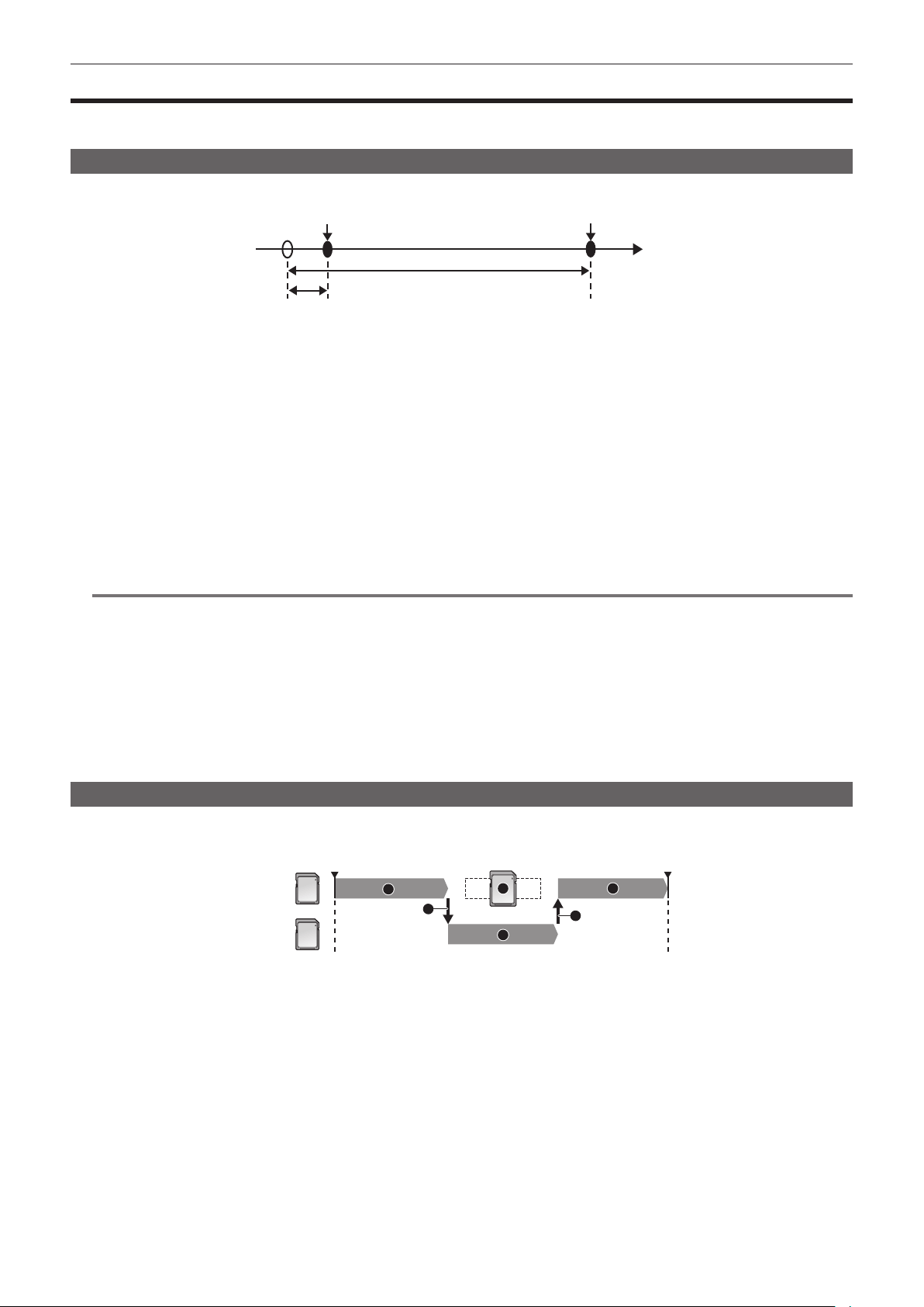
– 140 –
Chapter 5 Shooting — Special recording function
Special recording function
When recording into a memory card, pre-recording, relay recording, simultaneous recording, interval recording, and other special recording methods are
available.
Pre-recording
Records the video and audio from specic time before the operation to start the recording.
Operation to start recording Operation to stop recording
Actual recording time
Pre-recording time
(Time)
The pre-recording time varies depending on the setting of the [SYSTEM] menu → [FILE FORMAT]/[REC FORMAT].
f When [FILE FORMAT] is set to [P2]: Approximately 3 seconds
f When [FILE FORMAT] is set to [MOV], and [REC FORMAT] is set to [2160-29.97p/422ALL-I 400M], [2160-25.00p/422ALL-I 400M], or
[2160-23.98p/422ALL-I 400M]: Approximately 3 seconds
f When [FILE FORMAT] is set to [MOV], and [REC FORMAT] is set to [2160-59.94p/HEVC LongGOP 200M], [2160-59.94p/HEVC LongGOP 100M],
[2160-59.94p/420LongGOP 150M], [2160-50.00p/HEVC LongGOP 200M], [2160-50.00p/HEVC LongGOP 100M], [2160-50.00p/420LongGOP 150M],
[2160-29.97p/HEVC LongGOP 150M], [2160-29.97p/422LongGOP 150M], [2160-29.97p/420LongGOP 100M], [2160-25.00p/HEVC LongGOP 150M],
[2160-25.00p/422LongGOP 150M], [2160-25.00p/420LongGOP 100M], [2160-23.98p/HEVC LongGOP 150M], [2160-23.98p/422LongGOP 150M], or
[2160-23.98p/420LongGOP 100M]: Approximately 5 seconds
f When set to other than above: Approximately 10 seconds
1
Select the [RECORDING] menu → [PRE REC] → [ON].
[P] is displayed in the recording status display of the camera image screen.
2
Press the <REC> button.
@
NOTE
t The video and audio may not be able to record for specic time before in following cases.
- Immediately after the power is set to < j > (ON)
- Immediately after opening the menu
- Immediately after the memory card is inserted
- Immediately after playing back the recorded video
- Immediately after closing the thumbnail screen
- During the time from recording stop until completion of writing to the memory card
t It will be xed to free run regardless of the <TCG> switch position when pre-recording is enabled.
t The pre-recording is canceled once when three hours has past without starting the recording.
t For recording limitations of the pre-recording, refer to “Recording function that cannot be used simultaneously” (page 232).
t Pre-recording cannot be performed if the remaining recording capacity of the memory card is less than one minute.
Relay recording
When memory cards are inserted into the card slot 2 and the card slot 3, recording can continue on the other memory card if the remaining recording
capacity for one of the memory card is exhausted.
1
13
1
2
2
Card slot 2
Start shooting
Pause
Card slot 3
1 During recording
2 Automatically switch the recording target card slot
3 Replace with a different recordable memory card
1
Select the [RECORDING] menu → [2 SLOTS FUNC.] → [RELAY REC].
[RELAY] is displayed in the two slot function display of the camera image screen.
A slanted line is displayed on the [RELAY] display when the relay recording is not possible, such as when a memory card is not inserted in either of
the two card slots.
2
Press the <REC> button.
f The recording target switches to another memory card when the remaining recording capacity of one of the memory cards is exhausted during
recording and relay recording starts. The number of the card slot that became the recording target is displayed with black and white inverted.
Recording can be performed on three or more memory cards. Replace the memory card with no more remaining recording capacity after the
recording target has switched.
f To change the recording target card slot before starting the recording, press the USER button assigned to [SLOT SEL]. This will not operate during
recording.
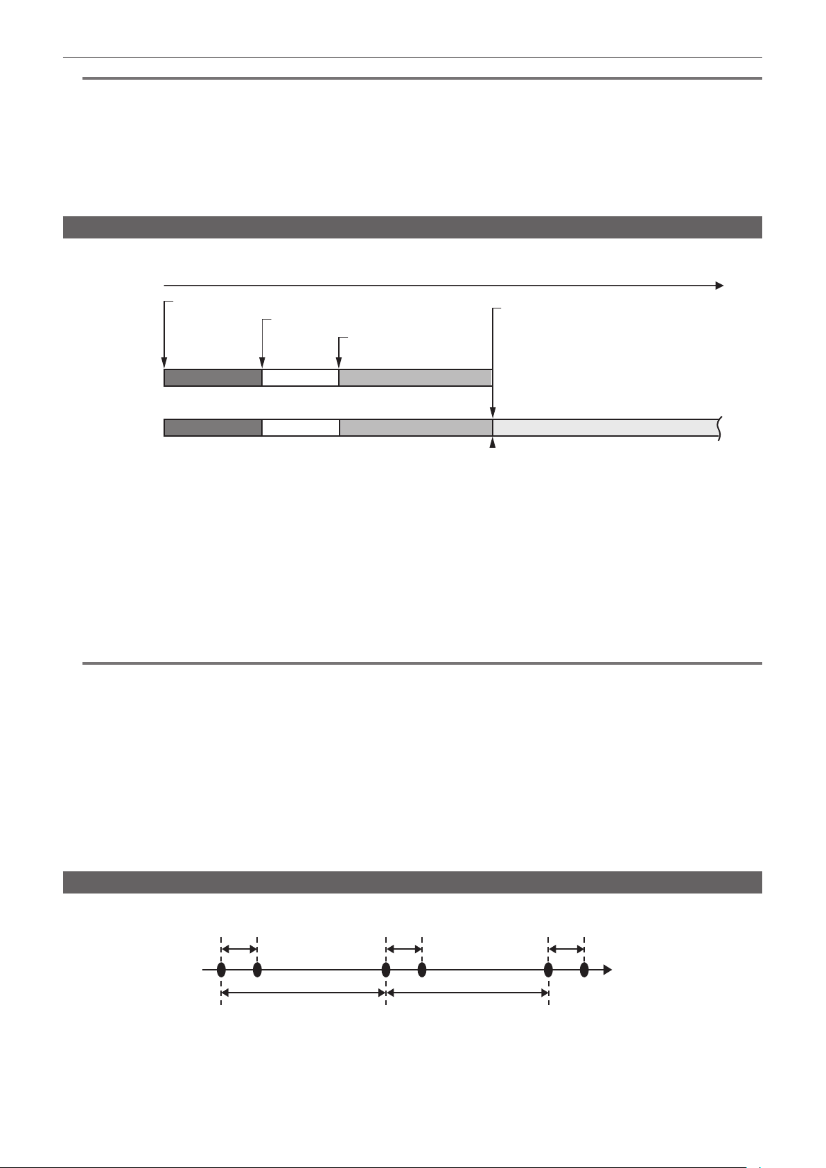
– 141 –
Chapter 5 Shooting — Special recording function
@
NOTE
t It may take some time to recognize the memory card when the memory card is inserted. When recording to three or more memory cards by replacing
a memory card while recording, replace the memory card with remaining capacity sufciently left on the memory card that is recording.
t The recording target cannot be switched when the remaining capacity of the relay memory card is less than one minute.
t The maximum continuous recording time for relay recording is ten hours.
t The recording is stopped once when the recording time of relay recording exceeds ten hours. The recording is automatically resumed after few
seconds.
t For recording limitations of the relay recording, refer to “Recording function that cannot be used simultaneously” (page 232).
t Relay recording is not possible between card slot 1 and card slot 2 or card slot 3.
t A clip recorded on three or more memory cards in succession through swapping them cannot be played back continuously.
Simultaneous recording
Memory cards are inserted into the card slot 2 and the card slot 3 to record the same video onto two memory cards.
Card slot 2
Card slot 3
A clip
A clip
Stand-by
Stand-by
B clip
B clip
Start recording
End recording
Start recording
C clip
End recording (no remaining space)
Memory card recording time
1
Select the [RECORDING] menu → [2 SLOTS FUNC.] → [SIMUL REC].
[SIMUL] is displayed in the two slot function display of the camera image screen.
A slanted line is displayed on the [SIMUL] display when the simultaneous recording is not possible, such as when a memory card is not inserted in
either of the two card slots.
2
Press the <REC> button.
f The simultaneous recording will stop when the remaining capacity of one of the memory cards is exhausted.
A slanted line is displayed in the [SIMUL] display when simultaneous recording is not possible.
To start the simultaneous recording again, replace the memory card that has run out of remaining capacity with another memory card, and then
press the <REC> button.
f When the <REC> button is pressed without replacing the memory card, standard recording is performed to the memory card with remaining
capacity.
@
NOTE
t Use of memory cards with the same Speed Class or capacity for simultaneous recording is recommended.
The recording may stop due to insufcient speed when memory cards with different Speed Classes or capacities are used. If the recording is stopped,
the video right before stopping may become invalid recording.
t Start the recording after both of the two memory cards have been recognized. When the recording starts before both memory cards are recognized,
the camera performs standard recording on one of the memory cards that has been recognized. The camera conrms the status of the memory card
every time the recording is completed. If both cards are recognized at that time, it will perform the simultaneous recording from the next recording.
t When recording to one of the memory cards stops due to a recording error during simultaneous recording, recording to the other memory card
continues.
t If there is remaining recording capacity on one of the memory cards after completing the simultaneous recording, the memory card with remaining
recording capacity automatically becomes the recording target. Standard recording will start when the <REC> button is pressed.
t Standard recording is performed when only one memory card is inserted even if the camera is set to simultaneous recording.
t Once the simultaneous recording is completed, [DEL LAST CLIP] (nal clip delete function) assigned to the USER button will not operate.
t For the folder name and the le name when performing simultaneous recording in MOV format, refer to “Handling recording data” (page 55).
t For recording limitations of the simultaneous recording, refer to “Recording function that cannot be used simultaneously” (page 232).
Interval recording
The camera will repeat one frame recording at each set interval.
1 frame recording 1 frame recording 1 frame recording
(Time)
Time set in [INTERVAL TIME] Time set in [INTERVAL TIME]
1
Select the [RECORDING] menu → [REC FUNCTION] → [REC MODE] → [INTERVAL].
[INTRVL] is displayed in the special recording function display of the camera image screen.
2
Set the time in the [RECORDING] menu → [REC FUNCTION] → [INTERVAL TIME].

– 142 –
Chapter 5 Shooting — Special recording function
3
Press the <REC> button.
f [I-REC] is displayed in red in the special recording function display of the camera image screen.
f The camera will repeat one frame recording at each set interval.
f To stop recording, press the <REC> or <STOP> button.
f Set the [RECORDING] menu → [REC FUNCTION] → [REC MODE] → [NORMAL] to clear the setting.
f Set whether to keep the settings after turning off the power in the [RECORDING] menu → [REC FUNCTION] → [REC MODE HOLD].
@
NOTE
t Audio is not recorded.
t Recorded data (data recorded until recording was stopped) is included in one clip.
t It will be xed to recording run regardless of the <TCG> switch position when interval recording is enabled.
t The [RECORDING] menu → [TC/UB] → [DF/NDF] is xed to [NDF].
t [SDI REC REMOTE] and [HDMI REC REMOTE] will not operate.
t If the length of the clip is less than three seconds when the recording is stopped, the image of the nal frame will be recorded to make the length of the
clip to three seconds.
t The recording is stopped once when the length of the clip exceeds ten hours in the interval recording. The recording is automatically resumed after
few seconds.
t For recording limitations of the interval recording, refer to “Recording function that cannot be used simultaneously” (page 232).
Recording the proxy data
The P2 recording of this camera can simultaneously record AVC-G6 format different from the main material recording as a proxy data.
f Resolution of the proxy data is the same as the main material recording.
f The le format is MOV format that is also appropriate to a nonlinear editing. For details of format, refer to “Specications” (page 236).
f When it is set to [V-Log] for recording the main material, the image to be recorded as a proxy data can be set to either [V-Log] or [V-709].
Also, when it is set to [HDR] for recording the main material, the image to be recorded as a proxy data can be set to either [SDR] or [HDR].
1
Select the [RECORDING] menu → [PROXY SETTING] → [PROXY REC] → [ON].
[PXY] is displayed next to the recording format in the camera image screen. This indicates that the recording of the proxy data is set.
2
Press the <REC> button.
The proxy data is simultaneously recorded with the main material.
f The proxy data is recorded in the memory card in the same card slot as the main material recording. Recording of the proxy data only is not
possible.
f The proxy data is recorded as an image audio le and a realtime metadata le.
- Image audio le: XXXXXXXX.MOV
- Realtime metadata le: XXXXXXXX.BIN
Time code and user bits information are recorded for each frame.
f [P] is displayed in the thumbnail screen on the clip with a proxy data recorded.
Also, the recording information of the proxy data can be conrmed in the clip information display screen.
For details, refer to “Conrming the detailed information of the proxy data” (page 142).
f The recorded proxy data cannot be played back in the camera. It can be played back with P2 Viewer Plus.
For information regarding P2 Viewer Plus, refer to the following website.
https://pro-av.panasonic.net/
@
NOTE
t When [FILE FORMAT] is set to anything other than [P2], the proxy data cannot be recorded.
t When [REC FORMAT] is set to AVC-G12, the proxy data cannot be recorded.
t For the recording restriction during the proxy recording, refer to “Recording function that cannot be used simultaneously” (page 232). Also, the
recording function of the proxy data cannot be simultaneously used with the streaming function (page 215).
t The clip with proxy data recorded in hybrid log gamma cannot be played back with P2 Viewer Plus for Windows. Play back using Windows Media
Player equipped with Windows, or VLC Media Player Ver.2.0 or later.
t Restoration of the proxy data is not possible. When a clip with proxy data is restored, only the main material is restored and the proxy data is deleted.
Conrming the detailed information of the proxy data
The detailed information of the proxy data for the recorded clip can be conrmed with the [THUMBNAIL] menu → [CLIP] → [INFORMATION] in the
thumbnail screen.
For the operation, refer to “Display of clip information” (page 181).
r Detailed information regarding the proxy data
[FORMAT] Displays the le format of the recording data.
[VIDEO CODEC] Displays the video codec information of the recording data.
[VIDEO FRAME RATE] Displays the video frame rate information of the recording data.
[VIDEO BIT RATE] Displays the video bit rate information of the recording data.
[VIDEO RESOLUTION] Displays the video resolution of the recording data.
[ASPECT RATIO] Displays the aspect ratio of the recording data.
[TC SUPER] Displays whether the TC (time code) display is superimposed to the recording video.
[AUDIO CODEC] Displays the audio codec information of the recording data.
[AUDIO BIT RATE] Displays the audio bit rate information of the recording data.

– 143 –
Chapter 5 Shooting — Special recording function
[AUDIO SAMPLING RATE] Displays the audio sampling rate information of the recording data.
[NUM.OF AUDIO CH] Displays the number of audio channels of the recording data.
Hot swap recording
Recording can span over two memory cards by inserting memory cards into the card slot 2 and the card slot 3.
Also, the memory card other than the one currently being recorded to can be swapped and recording can be continued on two or more memory cards.
Note, however, memory card recognition might slow down depending on the timing (immediately after pre-recording or before and after continuous
recording across two card slots) that the memory card is inserted. When inserting a memory card, make sure that there is at least one minute of
remaining recording capacity on the memory card to be recorded to.
@
NOTE
t Hot swap playback is not supported.
t Hot swap recording cannot be performed between card slot 1 and card slot 2 or 3.
Recording check function
f After recording ends, pressing the <RET> button on the lens automatically plays back the last few seconds of the latest clip.
Check whether video has been recorded properly. After playback, the camera is again ready to start recording.
f The recording check function can be assigned to a USER button. Set in the [CAMERA] menu → [USER SW] → [USER1] to [USER5] → [REC
CHECK].
REC check will not operate in following cases.
f When the power is turned on/off
f When restarted
f When the <THUMBNAIL> button is pressed
f When the memory card is inserted/ejected
f When formatted the memory card
f When the recording target card slot is switched by pressing the USER button assigned with [SLOT SEL]
f When switched to [CARD READER MODE]
f When set to the [RECORDING] menu → [2 SLOTS FUNC.] → [SIMUL REC]
f When either of the following settings are changed
-[SYSTEM] menu → [FILE FORMAT]
-[SYSTEM] menu → [REC FORMAT]
-[RECORDING] menu → [2 SLOTS FUNC.]
@
NOTE
t Set to the [CAMERA] menu → [SW MODE] → [RET SW] → [REC CHECK].
t During recording check, playback image is output not only to the viewnder but also to the video output terminals (<SDI OUT1> terminal, <SDI OUT2>
terminal, and <HDMI> terminal). Note that, when a backup device is connected and a backup image is being recorded, the playback image currently
under recording check will be recorded.
Clip metadata recording function
Information such as the name of the person recording or the name of the reporter, recording location, text memo, etc., can be loaded from the SD card
and recorded as a clip metadata.
Items of the clip metadata
The clip metadata has following items:
[GLOBAL CLIP ID] Displays the global clip ID indicating the recording condition of the clip.
[USER CLIP NAME] Displays the name of the clip that the user has set.*
1
[VIDEO] Displays [FRAME RATE] (frame rate of the clip), [PULL DOWN] (pull-down method), and [ASPECT RATIO]
(aspect ratio).
[AUDIO] Displays [AUDIO SAMPLING RATE] (sampling frequency of the recording audio) and [AUDIO BIT RATE]
(quantized number of bits for the recording audio).
[ACCESS] Displays [CREATOR] (name of the clip creator), [CREATION DATE] (date the clip was created), [LAST
UPDATE DATE] (date the clip was last updated), and [LAST UPDATE PERSON] (name of the person last
updated the clip).
[DEVICE] Displays [MANUFACTURER] (name of the manufacturer of the device used to record), [SERIAL NO.]
(serial number of the device used to record), and [MODEL NAME] (model name of the device used to
record).
[SHOOT] Displays [SHOOTER], [START DATE], [END DATE], [ALTITUDE], [LONGITUDE], [LATITUDE], [SOURCE],
and [PLACE NAME].
[SCENARIO] Displays [PROGRAM NAME], [SCENE NO.], and [TAKE NO.].
[NEWS] Displays [REPORTER], [PURPOSE], and [OBJECT].
[MEMO]*
2
Displays [NO.] (number of the text memo), [OFFSET] (frame position from the start of the clip where the
text memo is added), [PERSON] (person recording the text memo added to the clip), and [TEXT] (content
of the text memo).
[PROXY] Displays information such as the format of the proxy if the proxy is added.
*1 The recording method for [USER CLIP NAME] can be selected. For details, refer to “Selecting the recording method for [USER CLIP NAME]” (page 145).
*2 Always enter [TEXT] when entering [MEMO]. Recording only with [PERSON] or [OFFSET] is not possible.
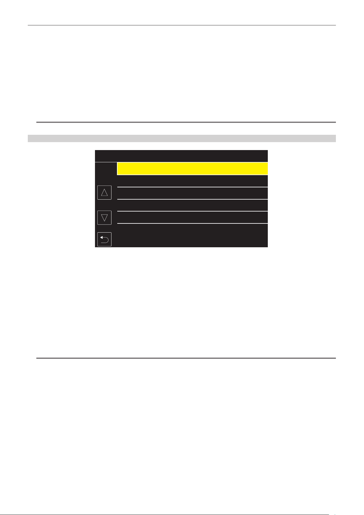
– 144 –
Chapter 5 Shooting — Special recording function
Following items can be set by loading a metadata upload le in the SD card.
f [USER CLIP NAME]
f [CREATOR], [LAST UPDATE PERSON] in [ACCESS]
f [SHOOTER], [PLACE NAME] in [SHOOT]
f [PROGRAM NAME], [SCENE NO.], [TAKE NO.] in [SCENARIO]
f [REPORTER], [PURPOSE], [OBJECT] in [NEWS]
f [PERSON], [TEXT] in [MEMO]
Other items will be automatically set during the recording.
The metadata upload le can be written in an SD card by using P2 Viewer Plus on a computer.
Install P2 Viewer Plus into the computer from the support desk in following website.
https://pro-av.panasonic.net/
For details of the SD card to be used, refer to “Memory cards supported on the camera” (page 51).
@
NOTE
t The le edited with anything other than P2 Viewer Plus will display [LOAD NG], and it may not be able to load.
Loading the clip metadata (metadata upload)
Meta01.P2
Meta05.P2
Meta04.P2
Meta02.P2
Meta03.P2
2021
-JAN
-6
2021
-JAN
-6
2021
-JAN
-6
2021
-JAN
-6
2021
-JAN
-6
Tokyo Meta 01
Fukuoka Meta
Nagoya Meta
Tokyo Meta 02
Osaka Meta
FILE NAME META NAME DATE
Fig. 1
1
Insert an SD card with a file describing the clip metadata (metadata upload file) into the camera.
2
Select the [RECORDING] menu → [REC META DATA] → [LOAD].
A list of metadata upload les stored in the specied folder in the SD card is displayed.
The card slot to perform loading and saving can be set in the [OTHERS] menu → [FILE] → [SLOT FOR LOAD/SAVE].
3
Select the name of the file to load. (Fig. 1)
4
Select [SET].
The le is loaded.
f The loaded metadata is held even if the power is turned off.
f For details about conrming the loaded data, refer to “Conrming and modifying the loaded metadata” (page 145).
f An error message may be displayed. For error message, refer to “Warning system” (page 227).
@
NOTE
t Only the characters that can be displayed in the camera will be displayed for the metadata upload le name and the metadata name. The characters
that cannot be displayed will be truncated. It will be displayed as [*****...] if all characters cannot be displayed.
t It will be displayed as [NO DATA.] if the metadata name is not described in the metadata upload le.
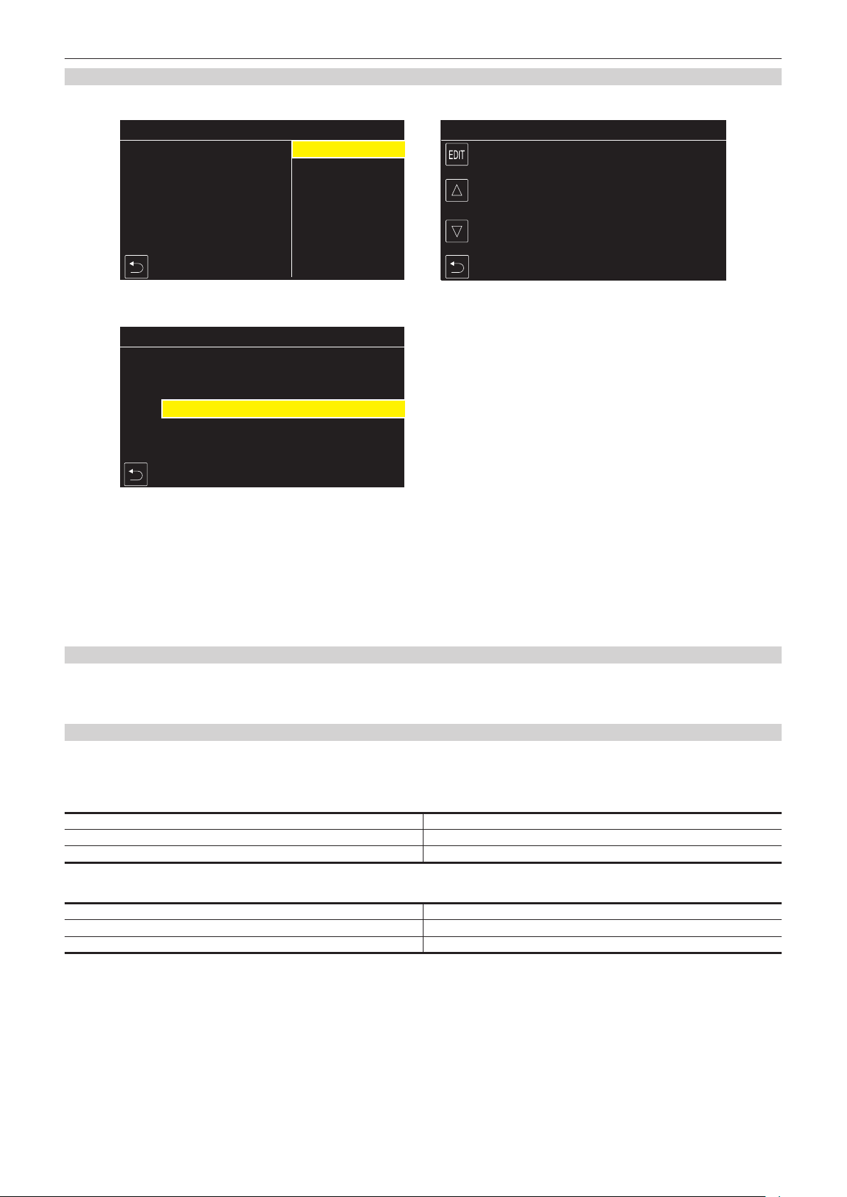
– 145 –
Chapter 5 Shooting — Special recording function
Conrming and modifying the loaded metadata
Content of the metadata loaded from the SD card can be conrmed.
Tokyo Tower
: 0001
:
Tokyo Meta 01
:
REC META DATA>USER CLIP NAME>EDIT
LOAD DATA
COUNT RESET
REC META DATA>USER CLIP NAME
LOAD DATA
COUNT
MENU>RECORDING>REC META DATA>PROPERTY
REC META DATA
REC ON
META NAME
USER CLIP NAME
CREATOR
LAST UPDATE PERSON
SHOOT
PLACE NAME
SCENARIO
NEWS
MEMO
Fig. 1 Fig. 2
Fig. 3
1
Select the [RECORDING] menu → [REC META DATA] → [PROPERTY].
A list of the metadata is displayed. (Fig. 1)
2
Select the item to confirm.
Content of each setting of the loaded metadata can be conrmed. (Fig. 2)
3
To modify the metadata, select [EDIT].
If there are multiple items that can be modied, a selection screen is displayed, so select the item to modify. (Fig. 3)
Setting to record/not record the loaded metadata
1
Set the [RECORDING] menu → [REC META DATA] → [RECORD] → [ON]/[OFF].
f The factory setting is [OFF].
Selecting the recording method for [USER CLIP NAME]
The recording method of [USER CLIP NAME] can be selected from two methods of either [TYPE1] or [TYPE2] in the [RECORDING] menu → [REC
META DATA] → [USER CLIP NAME].
r [TYPE1] (factory settings)
Condition of the clip metadata [USER CLIP NAME] to be recorded
If the clip metadata is loaded Uploaded data
If the clip metadata is not loaded, or set not to record the loaded clip metadata Same as [GLOBAL CLIP ID]
r [TYPE2]
Condition of the clip metadata [USER CLIP NAME] to be recorded
If the clip metadata is loaded
Uploaded data + [COUNT]*
If the clip metadata is not loaded, or set not to record the loaded clip metadata Same as [CLIP NAME]
* [COUNT] is displayed as a four-digit number.
[COUNT] is increased one at a time when a new clip is generated if the clip metadata is loaded and the recording method is set to [TYPE2].

– 146 –
Chapter 5 Shooting — Special recording function
Resetting [COUNT]
REC META DATA>USER CLIP NAME>EDIT
Fig. 1
LOAD DATA
COUNT RESET
1
Select the [RECORDING] menu → [REC META DATA] → [PROPERTY].
2
Select [USER CLIP NAME], then select [EDIT].
3
Move the cursor to [COUNT RESET]. (Fig. 1)
A conrmation screen is displayed.
4
Select [SET].
[COUNT] is set to 1.
Selecting recording the [CARD SERIAL]
Enable the function to record the card serial number to the metadata (text memo without offset).
1
Select the [RECORDING] menu → [REC META DATA] → [CARD SERIAL] → [ON].
Initializing the metadata setting
1
Select the [RECORDING] menu → [REC META DATA] → [INITIALIZE].
A conrmation screen is displayed.
2
Select [SET].
The settings in the [RECORDING] menu → [REC META DATA] including the loaded metadata are returned to the factory settings.
Shot mark recording function
Shot mark is a marker attached to the thumbnail of a clip to distinguish from other clips.
It is possible to display or play back only the clips with the shot mark.
Adding shot mark
r Assigning [SHOT MARK] to the USER button
1
Select the [CAMERA] menu → [USER SW] → [USER1] to [USER5] → [SHOT MARK].
r Adding shot mark
1
Press the USER button with [SHOT MARK] assigned while recording or while paused after recording.
[MARK ON] is displayed in the camera image screen, and the shot mark is added to the clip that is recording. In case of paused after recording, the
shot mark is added to the clip that was recorded immediately before.
[MARK OFF] is displayed and the shot mark is cleared by pressing again.
@
NOTE
t A shot mark can be added/cleared only on the clips in P2 format.
t A shot mark can also be added while displaying the thumbnail. (page 185)
t A shot mark cannot be added during recording in case of interval recording.
t A shot mark can only be added from the thumbnail display after recording in case of simultaneous recording.
t [SHOT MARK INVALID] is displayed when the USER button is pressed if the operation is invalid.
t Adding/clearing of the shot mark is not possible while playing back or paused during the playback.
t There are following restrictions when a shot mark is to be added/cleared for a linked clip such as a clip recorded across multiple memory cards, etc.
- All the memory cards constructing the clip must be inserted into the card slots.
- A shot mark is added only to the rst clip of the linked clips.

– 147 –
Chapter 5 Shooting — Special recording function
Selecting the resolution, codec, and frame rate for recording video
The resolution, codec, and frame rate of the recording video can be selected.
f [SYSTEM] menu → [FREQUENCY]: System frequency
f [SYSTEM] menu → [FILE FORMAT]: File format for recording
f [SYSTEM] menu → [REC FORMAT]: Signal format and codec mode for recording
f [SYSTEM] menu → [AUDIO SAMPLE RES.]: Number of bits of the audio to record (selectable if set to AVC-I100/AVC-I50)
When [FILE FORMAT] is set to [P2]
r Video
Resolution [FREQUENCY] [REC FORMAT]
1920×1080
[59.94Hz] [1080-59.94p/AVC-I100]
[1080-59.94p/AVC-I422]
[1080-59.94p/AVC-G25]
[1080-59.94p/AVC-G12]
[1080-59.94i/AVC-I200]
[1080-59.94i/AVC-I100]
[1080-59.94i/AVC-I50]
[1080-59.94i/AVC-G50]
[1080-59.94i/AVC-G25]
[1080-59.94i/AVC-G12]
[50.00Hz] [1080-50.00p/AVC-I100]
[1080-50.00p/AVC-I422]
[1080-50.00p/AVC-G25]
[1080-50.00p/AVC-G12]
[1080-50.00i/AVC-I200]
[1080-50.00i/AVC-I100]
[1080-50.00i/AVC-I50]
[1080-50.00i/AVC-G50]
[1080-50.00i/AVC-G25]
[1080-50.00i/AVC-G12]
1280×720
[59.94Hz] [720-59.94p/AVC-I200]
[720-59.94p/AVC-I100]
[720-59.94p/AVC-I50]
[720-59.94p/AVC-G50]
[720-59.94p/AVC-G25]
[720-59.94p/AVC-G12]
[50.00Hz] [720-50.00p/AVC-I200]
[720-50.00p/AVC-I100]
[720-50.00p/AVC-I50]
[720-50.00p/AVC-G50]
[720-50.00p/AVC-G25]
[720-50.00p/AVC-G12]
r Audio
Codec Number of audio channels Number of quantizing bits Sampling frequency
LPCM 4ch 24 bit (anything other than AVC-G12)
16 bit (AVC-I100/AVC-I50/AVC-G12)
48 kHz
When [FILE FORMAT] is set to [MOV]
r Video
Resolution [FREQUENCY] [REC FORMAT]
3840×2160
[59.94Hz] [2160-59.94p/420LongGOP 150M]
[2160-59.94p/HEVC LongGOP 200M]
[2160-59.94p/HEVC LongGOP 100M]
[2160-29.97p/420LongGOP 100M]
[2160-29.97p/HEVC LongGOP 150M]
[2160-29.97p/422LongGOP 150M]
[2160-29.97p/422ALL-I 400M]
[2160-23.98p/420LongGOP 100M]
[2160-23.98p/HEVC LongGOP 150M]
[2160-23.98p/422LongGOP 150M]
[2160-23.98p/422ALL-I 400M]
[50.00Hz] [2160-50.00p/420LongGOP 150M]
[2160-50.00p/HEVC LongGOP 200M]
[2160-50.00p/HEVC LongGOP 100M]
[2160-25.00p/420LongGOP 100M]
[2160-25.00p/HEVC LongGOP 150M]
[2160-25.00p/422LongGOP 150M]
[2160-25.00p/422ALL-I 400M]

– 148 –
Chapter 5 Shooting — Special recording function
Resolution [FREQUENCY] [REC FORMAT]
1920×1080
[59.94Hz] [1080-59.94p/422LongGOP 100M]
[1080-59.94p/422ALL-I 200M]
[1080-59.94i/422LongGOP 50M]
[1080-59.94i/422ALL-I 100M]
[1080-29.97p/422LongGOP 50M]
[1080-29.97p/422ALL-I 100M]
[1080-23.98p/422LongGOP 50M]
[1080-23.98p/422ALL-I 100M]
[50.00Hz] [1080-50.00p/422LongGOP 100M]
[1080-50.00p/422ALL-I 200M]
[1080-50.00i/422LongGOP 50M]
[1080-50.00i/422ALL-I 100M]
[1080-25.00p/422LongGOP 50M]
[1080-25.00p/422ALL-I 100M]
r Audio
Codec Number of audio channels Number of quantizing bits Sampling frequency
LPCM 4ch 24 bit 48 kHz

– 149 –
Chapter 5 Shooting — Selecting external reference signal and genlock setting
Selecting external reference signal and genlock setting
Locking the video signal to the external reference signal
The video signal output from the camera can be locked to the reference signal supplied from an external source.
The camera can receive external reference signal from the <GENLOCK IN> terminal.
Generator-locking to the reference signal supplied from the <GENLOCK IN> terminal
The HD-Y signal or a composite signal matching the system frame frequency is supplied to the <GENLOCK IN> terminal. To enable the reference signal
input to the <GENLOCK IN> terminal, it must be set to the [OTHERS] menu → [GENLOCK] → [GENLOCK] → [GL IN].
Adjust the horizontal phase of the reference signal and output signal at [H PHASE COARSE] and [H PHASE FINE].
Reference signal
System frequency
([REC FORMAT])
Supported signals
Composite signal HD-Y signal/tri-level SYNC signal
59.94i 480/59.94i 1080/59.94i
59.94p
50.00i 576/50i 1080/50i
50.00p
29.97p 480/59.94i 1080/59.94i
25.00p 576/50i 1080/50i
23.98p — 1080/23.98PsF

– 150 –
Chapter 5 Shooting — Setting of time data
Setting of time data
The camera provides time code, user bits, and date and time (real time) data as time data, and records in each frame synchronized with the video. The
time data is also recorded as the clip meta data. A counter data is built in.
Denition of time data
r Time code
<R-RUN> (recording run) and <F-RUN> (free run) can be switched by the <TCG> switch.
f Recording run: Advances only while recording. Recording is started with the value continuing from the last time code recorded previously.
f Free run: Advances regardless of the operation mode. It is advancing even when the power is turned off, so it can be treated equally as time.
Time data can also be recorded to the time code input to the <TC IN/OUT> terminal using slave lock.
@
NOTE
t The recording run will not be a continuous value for following cases.
- When recorded clips are deleted
- When recording is interrupted due to a malfunction of [REC WARNING], etc. during recording.
t It will be xed to free run when pre-recording is enabled.
t It will be xed to recording run when the interval recording is enabled.
r User bits
User bits are built-in. User bits are recorded in the clip. Also, it is output as LTC UB, VITC UB of the SDI signal.
The user setting value, time, date, time code, and frame rate information of shooting, and the clip name can be selected for recording.
The value at the time when the recording has started is recorded in the user bits of the clip meta data.
r Counter
Displays counter value on the time code display area of the viewnder/LCD monitor screen/display window when <DISPLAY> switch is set to
<COUNTER>.
Counter value is displayed as “hour:minute:second.frame”.
In addition, press the <RESET> button while the counter value is displayed to reset the counter value.
Either of the following settings can be set in the [RECORDING] menu → [REC COUNTER].
f [TOTAL]: The count is continuously cumulated until it is reset by pressing the <RESET> button. The counter value will be maintained even if the
memory card is replaced or the power is turned off.
f [CLIP]: Clears the counter value and starts counting from 0 each time recording starts. You can shoot while always checking the recording time of the
clip currently recording.
r Date/time (real time)
f The internal clock will be the reference for the measurement of the free run time code while the power is set to < h > (standby), time of the user bits,
and date data. Also, it will be used for generating the reference meta data for the le generation time and le name when the clip is recorded.
For details, refer to “Setting the date/time of the internal clock” (page 47).
Setting user bits
Set the user bits to be recorded.
1
Select the user bits to record in the [RECORDING] menu → [TC/UB] → [UB MODE].
[FRAME RATE] Selects the image information (such as frame rate) of the camera.
[USER] Selects the set user bits.
[TIME] Selects the local time. (hh, mm, ss)
[DATE] Selects the local date and time. (YY, MM, DD, hh)
[TC] Records the time code value as user bits.
[CLIP NAME] Records the value that CAM INDEX (one character) and CARD COUNT (three-digit number) are converted to ASCII
character code. Only enabled when the [SYSTEM] menu → [FILE FORMAT] → [MOV] is set.
Memory function of the user bits
Setting contents of the user bits is automatically recorded, and it is maintained even if the power is set to < h > (standby).
How to input user bits
By setting user bits, information such as memos (date, time) up to eight digits long (hexadecimal) can be recorded.
1
Set the <DISPLAY> switch to <UB>.
2
Set the <TCG> switch to <SET>.
3
Set the user bits by the cursor operation buttons.
f Screen display
- I: The digit to be set (ashing) moves to the right.
- Y: The digit to be set (ashing) moves to the left.
- `: The value of the digit to set (ashing) is incremented by one.
- {: The value of the digit to set (ashing) is decremented by one.
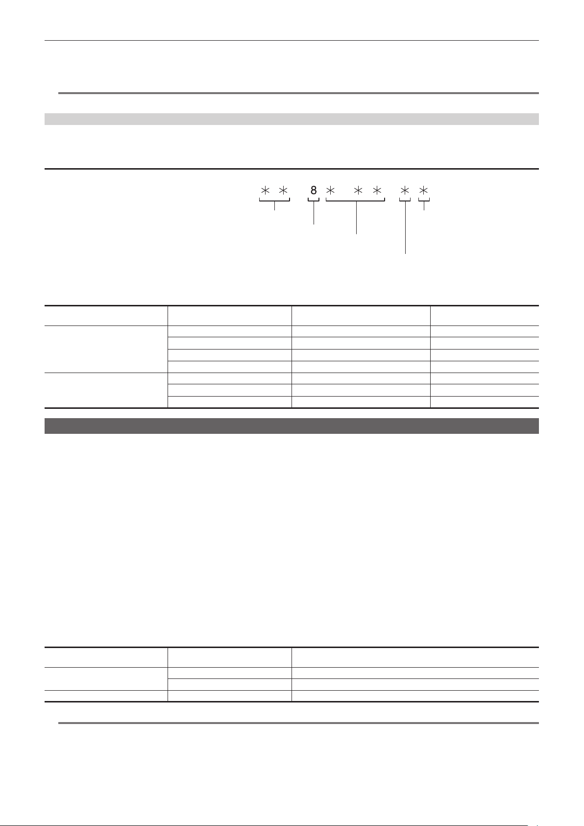
– 151 –
Chapter 5 Shooting — Setting of time data
4
Set the <TCG> switch to <F-RUN> or <R-RUN>.
5
Set to the [RECORDING] menu → [TC/UB] → [UB MODE] → [USER].
@
NOTE
t Thumbnail operations and menu operations on thumbnail operation section are not possible while the <TCG> switch is set to <SET>.
Frame rate information recorded on user bits
Recording the frame rate values for the image information shot/recorded according to the frame rate set in the [SYSTEM] menu → [REC FORMAT] to
user bits allows you to use on the editor (personal computer editing software).
Frame rate information
The relationship between frame rate, image pull-down, time code, and user bits is as follows.
Verification information on the right-hand six digits
Fixed values
REC mark
Camera video mode
Frame rate
r Camera video mode
The display of the camera video mode differs depending on the setting of following menus.
[FREQUENCY]
Recording frame frequency of [REC
FORMAT]
Display of frame rate Display of camera video mode
[59.94Hz] 23.98p 024 C
29.97p 030 8
59.94p 060 8
59.94i 060 0
[50.00Hz] 25.00p 025 A
50.00p 050 A
50.00i 050 2
Setting time code
1
Set the <DISPLAY> switch to <TC>.
2
Set the <TCG> switch to <SET>.
3
Set to the [RECORDING] menu → [TC/UB] → [DF/NDF].
f Set [DF] to advance the time code in the drop frame mode, and set [NDF] to advance it in the non-drop frame mode. However, note that the time
code runs by [NDF] at all times in the 23.98p mode.
4
Set the time code by the cursor operation buttons.
f Screen display
- I: The digit to be set (ashing) moves to the right.
- Y: The digit to be set (ashing) moves to the left.
- `: The value of the digit to set (ashing) is incremented by one.
- {: The value to set (ashing) is decremented by one.
5
Switch by the <TCG> switch.
To advance the time code by free run, switch to <F-RUN>, and to advance by recording run, switch to <R-RUN>.
r Setting range of time code
The range of the time code that can be set differs depending on the recording frame frequency of [REC FORMAT].
[FREQUENCY] Recording frame frequency of [REC
FORMAT]
Range of the time code that can be set
[59.94Hz] 59.94p, 29.97p, 59.94i 00:00:00:00 - 23:59:59:29
23.98p 00:00:00:00 - 23:59:59:23
[50.00Hz] 50.00p, 25.00p, 50.00i 00:00:00:00 - 23:59:59:24
@
NOTE
t Set the number of frames with a value that is a multiple of four when the recording frame frequency of [REC FORMAT] is set to 23.98p. The time code
to record will shift with any other value.
t Thumbnail operations and menu operations on thumbnail operation section are not possible while the <TCG> switch is set to <SET>.
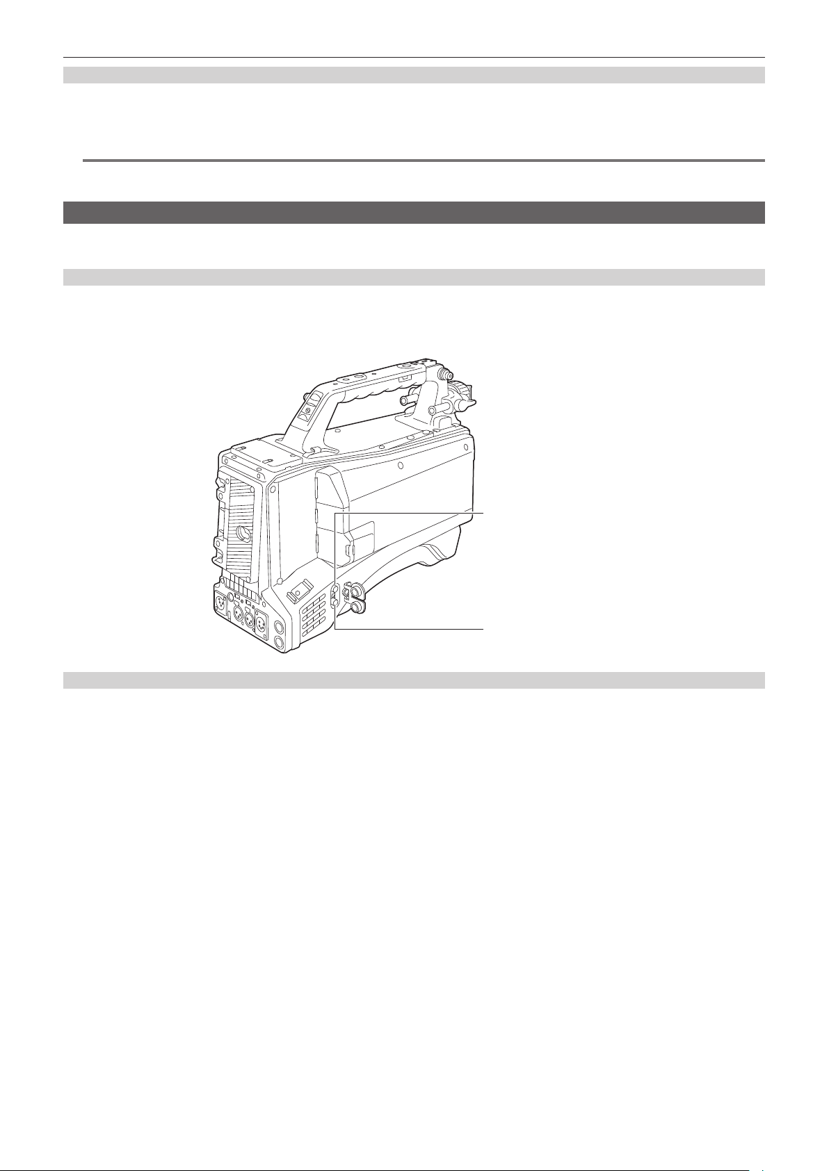
– 152 –
Chapter 5 Shooting — Setting of time data
Time code function during battery replacement
The operation of the time code generator will continue by the backup mechanism functioning even when replacing the battery.
The time code of the free run may shift when any item in the [SYSTEM] menu → [FREQUENCY]/[FILE FORMAT]/[REC FORMAT] is changed. Set the
power to < j > (ON) again, conrm the time code, and set it again if necessary.
@
NOTE
t When the power switch has been switched to < j > (ON) → < h > (standby) → < j > (ON), the backup accuracy of the time code in the free run mode
is approximately ±2 frames.
Externally locking the time code
The internal time code generator of the camera can be locked to an external time code generator. In addition, the time code generator of an external
equipment can be locked to the internal time code generator of the camera.
Example of connections for external locking
As shown in the gure, connect both the reference video signal and the reference time code.
For details on reference signal and genlock, refer to “Selecting external reference signal and genlock setting” (page 149).
r When locking onto an external signal
Reference time code
<GENLOCK IN> terminal
<TC IN/OUT> terminal
Reference video signal
External lock operation procedure
To externally lock the time code, follow the steps below.
1
Set the <TCG> switch to <F-RUN>.
2
Set the <DISPLAY> switch to <TC>.
3
Set to the [OTHERS] menu → [GENLOCK] → [GENLOCK] → [GL IN].
4
Set to the [RECORDING] menu → [TC/UB] → [TC IN/OUT SEL] → [TC IN].
5
Input a reference time code and reference video signal that are in a phase relationship (that conforms to time code specifications)
to the <TC IN/OUT> and <GENLOCK IN> terminals.
The built-in time code generator is locked to the reference time code. When approximately ten seconds has elapsed after locking, the externally
locked status will be held even if the reference time code from the external device is disconnected.
f When the input reference signal of genlock is disrupted, recording cannot be performed normally. [TEMPORARY PAUSE]/[IRREGULAR SIG] is
displayed in the viewnder screen, and the clip is divided. The continuity of the time code is not guaranteed. Recording will be resumed when the
signal returns to normal.
f When the time code is externally locked, the time code is instantaneously locked to the external time code, the same value as the value of the
external time code is displayed on the counter display area. Do not start recording for several seconds until the sync generator has stabilized.
Furthermore, lock the time code to the <TC IN/OUT> terminal signal.
f When externally locking in 23.98p mode, be sure to input non-drop frame time codes. An external lock is not possible using drop frames. When the
external lock is activated, images may look corrupted. However, this is an operation to match the 5-frame cycle so it is not a malfunction.
f When set to the [RECORDING] menu → [PRE REC] → [ON], disrupted images or stopped time codes may be recorded if the time code is slave
locked by entering an external time code to the <TC IN/OUT> terminal right before recording.
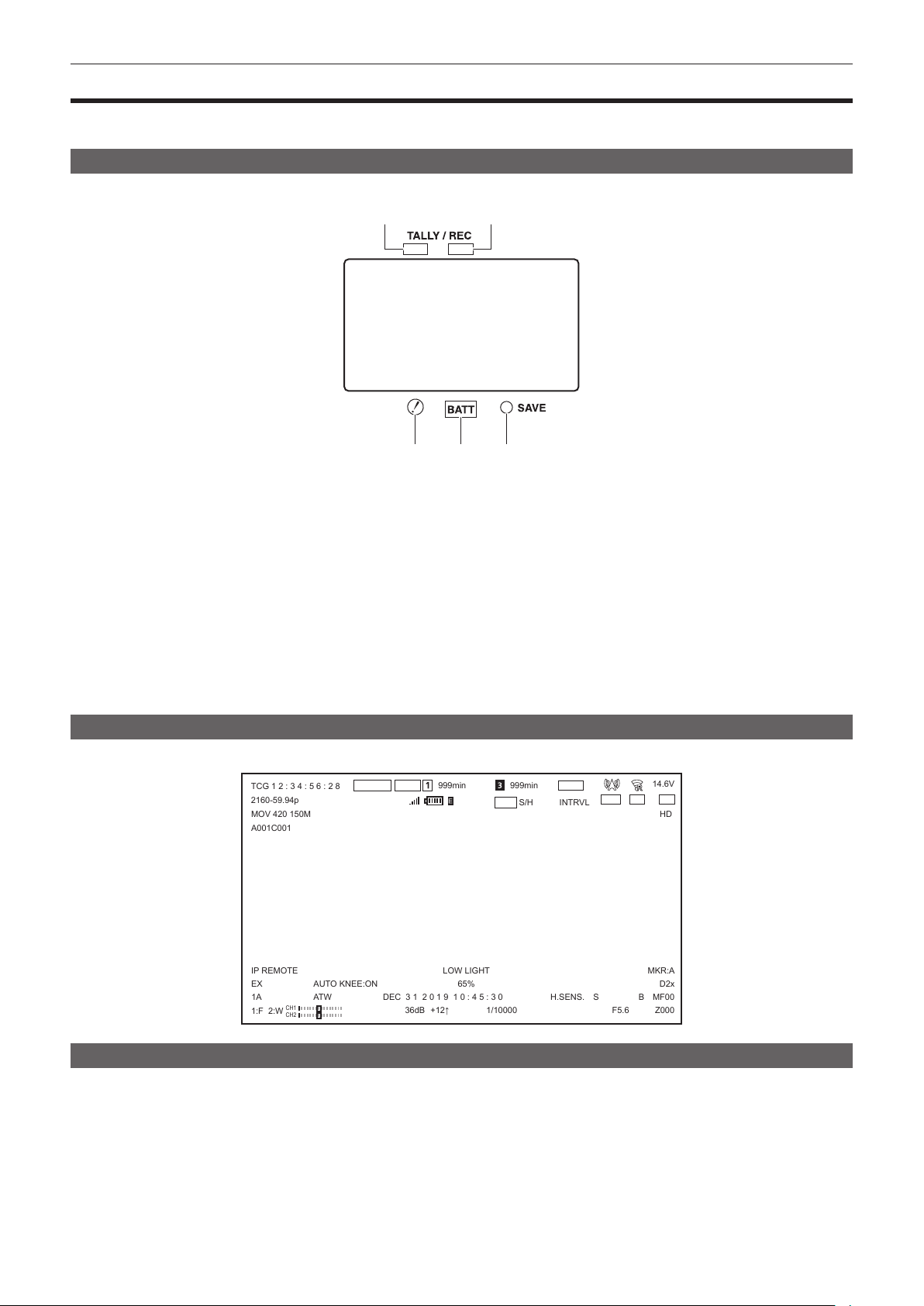
– 153 –
Chapter 5 Shooting — Display of the viewnder status
Display of the viewnder status
In addition to video, the viewnder displays messages that indicate the camera settings and operation status, a center marker, safety zone marker,
zebra patterns, and other information.
Lamp display in the viewnder
The example is for the AJ-CVF50G. (For information on the viewnder, refer to the Operating Instructions for the optional viewnder.)
1 2
3
4
5
1 Green tally lamp
Lights up green if a green tally signal is received from the Camera Control Unit.
2 TALLY/REC (recording) lamp
Illuminated in red during recording, and ashes if an abnormality occurs.
For details, refer to “Warning system” (page 227).
3 [!] lamp
[!] lamp of the viewnder illuminates when the items set to [ON] in the [VIDEO OUT/LCD/VF] menu → [!LED] are enabled.
4 BATT (battery) lamp
Starts ashing few minutes before the battery voltage drops and the battery charge runs out.
It is illuminated after the battery is completely at.
To prevent operation from being interrupted, replace the battery before it is nearly at.
For details, refer to “Warning system” (page 227).
5 SAVE lamp
The lamp is always out.
Conguration of status display on viewnder screen
The screen displayed in normal status is displayed as shown below.
TCG 1 2 : 3 4 : 5 6 : 2 8
2160-59.94p
MOV 420 150M
A001C001
1A
IP REMOTE
36dB
+12↑
1/10000
F5.6
S
B
H.SENS.
DEC 3 1 2 0 1 9 1 0 : 4 5 : 3 0
LOW LIGHT
AUTO KNEE:ON
65%
Z000
MF00
D2x
MKR:A
ATW
S/H
INTRVL
HD
14.6V
999min
999min
FBC1
RELAY
HDR CAC
+
CH1
CH2
eP2
R E C
REC
B . D E V
1:F 2:W
EX
Selecting display items on viewnder screen
The items to display in the output image can be selected.
For details on each items, refer to [INDICATOR] (page 89).
1
Set display of each item in the [VIDEO OUT/LCD/VF] menu → [INDICATOR].
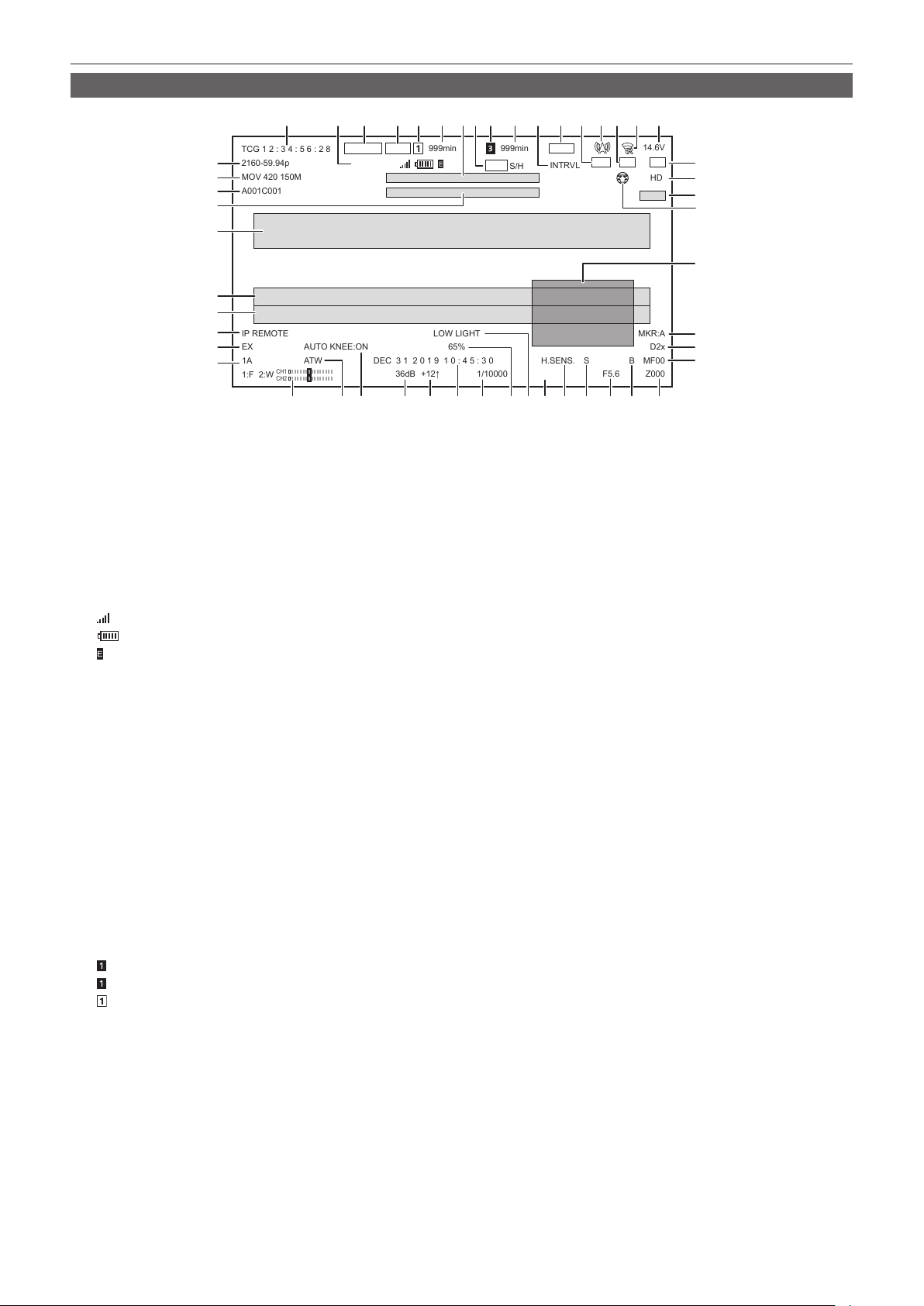
– 154 –
Chapter 5 Shooting — Display of the viewnder status
Screen display during shooting
TCG 1 2 : 3 4 : 5 6 : 2 8
2160-59.94p
MOV 420 150M
A001C001
1A
IP REMOTE
36dB
+12↑
1/10000
F5.6
S
B
H.SENS.
DEC 3 1 2 0 1 9 1 0 : 4 5 : 3 0
LOW LIGHT
AUTO KNEE:ON
65%
Z000
MF00
D2x
MKR:A
ATW
S/H
INTRVL
HD
14.6V
999min
999min
FBC1
RELAY
HDR CAC
+
CH1
CH2
eP2
R E C
REC
B . D E V
1:F 2:W
EX
1 4 5 7 8 9 10 11 12 13
40 39 38 36
37 35 3234 33
3031 2829 2627
49
20
22
21
23
48
47
50
46
18
19
24
25
45
44
43
42
41
3 6 14
15 16 172
1 Time code/User bits/Counter data
Displays the time data selected with the <DISPLAY> switch.
f [TCG **:**:**:**]: Displays the time code. [TCR **:**:**:**] will be displayed during playback.
[TCG] is displayed with black and white inverted during the slave lock into the external input time code.
f [UBG ** ** ** **]: Displays the user bits. [UBR ** ** ** **] will be displayed during playback.
f [CLP **:**:**:**]: Displays the counter value of each clip. This is displayed when the [RECORDING] menu → [REC COUNTER] → [CLIP] is
set. Displays the counter value of the clip being played back during playback.
f [**:**:**:**]: Displays the cumulative counter value from the reset position. This is displayed when the [RECORDING] menu → [REC
COUNTER] → [TOTAL] is set.
2 Bonding Device Status
Displays the device status received from the bonding device with up to rst ve letters and the following symbol.
f
: The signal reception strength of the bonding device is displayed in 6 levels.
f
: The remaining battery of the bonding device is displayed in 6 levels.
f
: Displayed when there is an error in the bonding device.
f (No display): Bonding device is not connected.
3 Recording status
f [REC]: Recording.
f [REC] (Flashing): Processing to stop the recording.
f [P]: Recording is stopped with pre-recording is enabled.
f (No display): It is in one of the following conditions.
-Recording is stopped with pre-recording is disabled.
-It is set to the [NETWORK] menu → [NETWORK FUNC] → [NDI|HX].
4 Recording media
Setting status of the [RECORDING] menu → [REC MEDIA] is displayed.
f [eP2]: Displays when set to the [RECORDING] menu → [REC MEDIA] → [expressP2].
f [mP2]: Displays when set to the [RECORDING] menu → [REC MEDIA] → [microP2/SD].
f (No display): Set to the [NETWORK] menu → [NETWORK FUNC] → [NDI|HX].
5 Status of the card slot 1 or 2
Displays status of the card slot 1 when the [RECORDING] menu → [REC MEDIA] → [expressP2] is set.
Displays status of the card slot 2 when the [RECORDING] menu → [REC MEDIA] → [microP2/SD] is set.
The status are as follows:
f
: Not target for recording.
f
(ashing): Recognizing the memory card.
f
: Recording target.
f (No display): It is in one of the following conditions.
-A memory card has not been inserted.
-The memory card cannot be recognized.
-It is set to the [NETWORK] menu → [NETWORK FUNC] → [NDI|HX].
6 Remaining capacity and status of the memory card in card slot 1 or 2
Displays the remaining capacity and status of the memory card in card slot 1 or 2.
f [0min]…[999min]: Displays remaining capacity of the memory card. Remaining capacity of 999 minutes or more is displayed as [999min].
-The display will ash when the remaining capacity of the memory card becomes two minutes or less.
-The remaining capacity of the memory card available for simultaneous recording (remaining capacity for the memory card of the two memory
cards with less remaining capacity) is displayed when simultaneous recording is performed.
f [WP]: It is write protected. The write-protected switch on the memory card is set to the Protect side or the LOCK side.
f [END]: Memory card has no remaining capacity.
f [ERR]: Memory card that cannot record is inserted. Displayed when the card is recognized but cannot be used, such as having a format error, or
not being a memory card.

– 155 –
Chapter 5 Shooting — Display of the viewnder status
f [!SDXC]: Recording format is set to MOV but SDXC memory card, expressP2 card, or 64 GB microP2 card is not inserted.
f (No display): It is in one of the following conditions.
-A memory card has not been inserted.
-The memory card cannot be recognized.
-It is set to the [NETWORK] menu → [NETWORK FUNC] → [NDI|HX].
7 Message display area for wireless audio warning and cooling fan stop
Displays a warning when the wireless audio reception status becomes poor.
Displays a message when the cooling fan has stopped.
8 SDI/HDMI remote control status
Displays the control status of the recording start and recording stop on the external equipment connected to the <SDI OUT1>/<SDI OUT2>/<HDMI>
terminals.
f [REC S/H]: Recording instruction is output to the output from the <SDI OUT1>/<SDI OUT2>/<HDMI> terminals.
f [S/H]: Pause instruction is output to the output from the <SDI OUT1>/<SDI OUT2>/<HDMI> terminals.
f [REC SDI]: Recording instruction is output to the output from the <SDI OUT1>/<SDI OUT2> terminals.
f [SDI]: Pause instruction is output to the output from the <SDI OUT1>/<SDI OUT2> terminals.
f [REC HDMI]: Recording instruction is output to the output from the <HDMI> terminal.
f [HDMI]: Pause instruction is output to the output from the <HDMI> terminal.
9 Status of card slot 3
It is not displayed when set to the [RECORDING] menu → [REC MEDIA] → [expressP2].
f
: Not target for recording.
f
(ashing): Recognizing the memory card.
f
: Recording target.
f (No display): It is in one of the following conditions.
-A memory card has not been inserted.
-The memory card cannot be recognized.
-The [NETWORK] menu → [NETWORK FUNC] → [NDI|HX] is set.
10 Remaining capacity and status of the memory card in card slot 3
Displays the remaining capacity and status of the memory card in card slot 3.
It is not displayed when set to the [RECORDING] menu → [REC MEDIA] → [expressP2].
f [0min]…[999min]: Displays remaining capacity of the memory card. Remaining capacity of 999 minutes or more is displayed as [999min].
-The display will ash when the remaining capacity of the memory card becomes two minutes or less.
-The remaining capacity of the memory card available for simultaneous recording (remaining capacity for the memory card of the two memory
cards with less remaining capacity) is displayed when simultaneous recording is performed.
f [WP]: It is write protected. The write-protected switch of the memory card is set to the LOCK side.
f [END]: Memory card has no remaining capacity.
f [ERR]: Memory card that cannot record is inserted. Displayed when the card is recognized but cannot be used, such as having a format error, or
not being a memory card.
f [!SDXC]: Recording format is set to MOV but SDXC memory card or 64 GB microP2 card is not inserted.
f (No display): It is in one of the following conditions.
-A memory card has not been inserted.
-The memory card cannot be recognized.
-It is set to the [NETWORK] menu → [NETWORK FUNC] → [NDI|HX].
11 Special recording function
Displays the status of special recording function.
f [INTRVL]: Interval recording is enabled.
f [I-REC]: During interval recording or recording is paused.
f (No display): It is in one of the following conditions.
-Interval recording is disabled.
-It is set to the [NETWORK] menu → [NETWORK FUNC] → [NDI|HX].
12 Two-slot function
Displays the setting status of the recording function using two card slots.
It is displayed with a slanted line if it is in a condition that cannot perform two-slot function even if each function is enabled.
f [RELAY]: Relay recording is enabled.
f [SIMUL]: Simultaneous recording is enabled.
f [NDI|HX]: It is set to the [NETWORK] menu → [NETWORK FUNC] → [NDI|HX].
f (No display): In standard recording status.
13 Flash band compensation function
f [FBC1] or [FBC2]: Flash band compensation function is enabled.
14 Streaming status
Displays the streaming status.
f
: The camera is connected to a device to receive the streaming video, and the streaming video is distributed.
f
(ashing): When the camera is trying to connect to a device to receive the streaming video
f
: Streaming video is not being streamed.
f
: There is an error in the streaming function and cannot operate.
f (No display): Streaming function is disabled
15 High dynamic range function/dynamic range stretcher function/V-Log recording function
f [HDR]: It is set to the [SCENE FILE] menu → [GAMMA MODE SEL] → [HLG].

– 156 –
Chapter 5 Shooting — Display of the viewnder status
f [DRS]: Dynamic range stretcher function is enabled.
It is not displayed when the [SYSTEM] menu → [COLOR SETTING] → [V-Log] is set.
16 Connection status of the wired LAN, wireless LAN, and USB tethering
Displays the connection status of the wired LAN, wireless LAN, and USB tethering.
f
: Set to wireless LAN and not connected to the ROP app.
f
: Set to wireless LAN and connected to the ROP app.
f
: Set to wireless LAN but the wireless LAN is not operating properly.
f
: Set to wired LAN and not connected to the ROP app.
f
: Set to wired LAN and connected to the ROP app.
f
: Set to wired LAN but the wired LAN is not operating properly.
f
: When set to the USB tethering and the ROP is not connected
f
: When set to the USB tethering and the ROP is connected
f
: When set to the USB tethering and the USB tethering is not operating properly
f (No display): Wired LAN, wireless LAN, and USB tethering are disabled.
17 Remaining battery level
f [**.*V]: Displays the charge level of batteries with no charge level information in 0.1 V units. The display will ash when the remaining charge is
at the near end setting value or below.
f [***%]: Displays the charge level of batteries with charge level information in %. The display will ash when the remaining charge is at the near
end setting value or below.
f [EMP]: Displayed when there is no charge level on batteries with charge level information or the level is at the near end setting value or below.
f [MAX]: Displayed when batteries with charge level information are fully charged.
18 Chromatic aberration compensation function
f [CAC]: Chromatic aberration compensation function is enabled.
19 Gamma mode
Setting value for the gamma mode selected in the [SCENE FILE] menu → [GAMMA MODE SEL] is displayed.
f [HD]
f [SD]
f [FLK1]
f [FLK2]
f [FLK3]
f [FREC]
f [VREC]
f [HLG]
20 Scene le name
Name of the scene le selected in the [SCENE FILE] menu → [FILE SELECT] is displayed.
It is not displayed when the [SYSTEM] menu → [COLOR SETTING] → [V-Log] is set.
21 Upload status display
Displays the status of the contents upload.
f
: When the upload function is enabled and before starting or after completing the upload
f
: When uploading
f
: When an upload transfer error has occurred
22 Waveform monitor
Displays the video status in waveform or vector.
Displayed only on the LCD monitor and the viewnder.
23 Type of marker
Displays the type of currently displayed marker in the STATUS screen of the mode check.
[MKR:A]: Displays the marker type [A].
[MKR:B]: Displays the marker type [B].
[MKR:OFF]: Marker is not displayed.
24 Digital zoom
Displays the digital zoom ratio.
f [D2×]: Two times
f [D3×]: Three times
f [D4×]: Four times
25 Focus
Displays the focus value.
The display of the focus value follows the setting in the [VIDEO OUT/LCD/VF] menu → [INDICATOR] → [ZOOM/FOCUS].
f [MF**]: Displays in the position value from [00] to [99] when set to the [VIDEO OUT/LCD/VF] menu → [INDICATOR] → [ZOOM/FOCUS] →
[NUMBER].
f [MF****ft]: Displays in feet unit when set to the [VIDEO OUT/LCD/VF] menu → [INDICATOR] → [ZOOM/FOCUS] → [mm/feet].
f [MF****m]: Displays in meter unit when set to the [VIDEO OUT/LCD/VF] menu → [INDICATOR] → [ZOOM/FOCUS] → [mm/m].
f (No display): Focus value cannot be acquired.
26 Zoom
Displays the zoom value.
The display of the zoom value follows the setting in the [VIDEO OUT/LCD/VF] menu → [INDICATOR] → [ZOOM/FOCUS].
f [Z***]: Displays in the position value from [000] to [999] when set to the [VIDEO OUT/LCD/VF] menu → [INDICATOR] → [ZOOM/FOCUS] →
[NUMBER].

– 157 –
Chapter 5 Shooting — Display of the viewnder status
f [Z**.*]: Displays in millimeter unit when set to the [VIDEO OUT/LCD/VF] menu → [INDICATOR] → [ZOOM/FOCUS] → [mm/feet] or [mm/m].
f (No display): Zoom value cannot be acquired.
27 Super black
f [B]: Displayed when the super black function is enabled.
28 Iris
Displays the F value.
Displayed when a lens with an F value display function is used.
Flashes when changing the setting value of the iris override function.
f [F***]: Displays the F value of the lens.
f [OPEN]: Displayed when the lens aperture is open.
f [CLOSE]: Displayed when the lens aperture is closed.
f [NC]: Displayed when the lens cable is not connected.
29 Super iris
f [S]: Displayed when the super iris function is enabled.
30 High-sensitivity mode
f [H.SENS.]: Displayed when set to the [SYSTEM] menu → [SHOOTING MODE] → [HIGH SENS.].
31 Iris override
Displays the compensation level when the iris override function is enabled.
Flashes when changing the compensation level.
f [+]: Aperture opens by about 0.5.
f [++]: Aperture opens by about 1.
f [−]: Aperture closes by about 0.5.
f [−−]: Aperture closes by about 1.
f (No display): It is in one of the following conditions.
-Iris is a reference value.
-Iris override function is disabled.
32 Luminance drop message display
Displayed when luminance has dropped.
33 Luminance of Y GET
Displays the luminance level in unit of [%] or [STOP] when the Y GET function is operating. ([STOP] is displayed as [ST])
The display unit follows the setting in the [VIDEO OUT/LCD/VF] menu → [EI ASSIST] → [Y GET UNIT].
The display unit is xed to [%] when the [SCENE FILE] menu → [GAIN/ISO MODE] is set to [dB].
34 Shutter speed
f [1/****]: Displays the shutter speed.
f [w1/*****]: Displays the shutter speed in time (minutes) when synchro scan function is enable and the [SCENE FILE] menu → [SYNC SCAN
TYPE] → [sec] is set.
f [w*****d]: Displays the shutter speed in open angle when synchro scan function is enable and the [SCENE FILE] menu → [SYNC SCAN
TYPE] → [deg] is set.
f [HALF]: Displays when the [CAMERA] menu → [SHUTTER SPEED] → [POSITION1] to [POSITION6] → [HALF] is set and the position is selected.
f (No display): Electronic shutter function is disabled.
35 Date and time information
Displays the date and time information.
The content displayed follows the setting in the [VIDEO OUT/LCD/VF] menu → [INDICATOR] → [DATE/TIME]. (page 92)
The display order for the year, month, and date follows the setting in the [OTHERS] menu → [CLOCK] → [DATE FORMAT].
f [Y-M-D]: Displays in yyyy mmm dd hh:mm:ss format.
f [M-D-Y]: Displays in mmm dd yyyy hh:mm:ss format.
f [D-M-Y]: Displays in dd mmm yyyy hh:mm:ss format.
-mmm: Month (JAN (January), FEB (February), MAR (March), APR (April), MAY (May), JUN (June), JUL (July), AUG (August), SEP (September),
OCT (October), NOV (November), DEC (December))
-dd: Date
-yyyy: Year
-hh: Hour
-mm: Minute
-ss: Second
36 Digital super gain
Displays the digital super gain value when the digital super gain function is enabled.
37 Gain
Displays the gain value.
f [**dB]: Displays the current gain value.
f [AGC]: Displayed when the auto gain control is enabled.
38 Auto knee
f [AUTO KNEE:ON]: Auto knee function is enabled.
f [AUTO KNEE:OFF]: Auto knee function is disabled.
39 Color temperature
Displays the position and color temperature selected with the <WHITE BAL> switch.
f [ATW]: Displayed when the auto tracking white balance is operating.
f [LOCK]: Displayed when the auto tracking white balance is locked.

– 158 –
Chapter 5 Shooting — Display of the viewnder status
f [A*****K]: The <WHITE BAL> switch is set to memory <A>.
f [B*****K]: The <WHITE BAL> switch is set to memory <B>.
f [P*****K]: The <WHITE BAL> switch is set to <PRST>.
40 Audio level meter
Displays the status of audio input setting and recording level.
Audio channel to display can be changed using the audio channel selector switch.
f [1:* 2:*]: Displayed when the audio channel selector switch is set to <CH1/2>.
Audio input setting for audio channel 1 and audio channel 2 are displayed in *.
F is displayed when the <AUDIO IN CH1>/<AUDIO IN CH2> switch is set to <FRONT>. W is displayed when the <AUDIO IN CH1>/<AUDIO IN
CH2> switch is set to <W.L.>. R is displayed when the <AUDIO IN CH1>/<AUDIO IN CH2> switch is set to <REAR>.
f [3:* 4:*]: Displayed when the audio channel selector switch is set to <CH3/4>.
Audio input setting for audio channel 3 and audio channel 4 are displayed in *.
F is displayed when the <AUDIO IN CH3>/<AUDIO IN CH4> switch is set to <FRONT>. W is displayed when the <AUDIO IN CH3>/<AUDIO IN
CH4> switch is set to <W.L.>. R is displayed when the <AUDIO IN CH3>/<AUDIO IN CH4> switch is set to <REAR>.
A white frame is displayed at the position of the reference level set in the [AUDIO] menu → [REC CH SETTINGS] → [HEAD ROOM]. (Eighth from
the left when set to [20dB], ninth from the left when set to [18dB])
f
: Displayed when audio cannot be recorded.
41 Filter position
Displays the <ND FILTER> dial position with numbers 1 to 4 and <CC FILTER> dial position with alphabet A to D.
[-] will ash by inverting black and white when the lter position is not set correctly.
42 Extender
f [EX]: Displayed when the lens extender function is functioning.
43 Remote control status in an IP connection
f [IP REMOTE]: Displayed when the remote control is possible in the IP connection.
f [IP REMOTE] (ashing): Displayed when waiting for the connection in the IP connection.
f (No display): Remote control function in an IP connection is disabled.
44 Error display of auto black balance
Displays the status when the adjustment result of the auto black balance was abnormal.
45 Error display of auto white balance
Displays the status when the adjustment result of the auto white balance was abnormal.
46 Message display area
Displayed when there is a message or warning about the camera status.
47 Message for invalid lter position
Message is displayed when power is turned on if the <ND FILTER>/<CC FILTER> dial is not set correctly.
Message is displayed when performing the auto white balance if the <CC FILTER> dial is not set correctly.
48 Clip name
Displays the name of the clip being recorded with up to eight characters from the start.
49 Recording format
Displays the le format set in the [SYSTEM] menu → [FILE FORMAT] and the recording codec set in the [SYSTEM] menu → [REC FORMAT].
It is not displayed when set to the [NETWORK] menu → [NETWORK FUNC] → [NDI|HX].
f [P2 AVC-I200]
f [P2 AVC-I100]
f [P2 AVC-I50]
f [P2 AVC-I422]
f [P2 AVC-G50]
f [P2 AVC-G25]
f [P2 AVC-G12]
f [MOV 420 150M]
f [MOV 420 100M]
f [MOV 422 150M]
f [MOV 422 100M]
f [MOV 422 50M]
f [MOV HEVC 200M]
f [MOV HEVC 150M]
f [MOV HEVC 100M]
f [MOV ALL-I 400M]
f [MOV ALL-I 200M]
f [MOV ALL-I 100M]
f [PXY]: Displayed when the camera is set to record the proxy data in P2 format.
50 System resolution/system frequency
Displays the system resolution and the system frequency set in the [SYSTEM] menu → [REC FORMAT].
f [2160-59.94p]
f [2160-50.00p]
f [2160-29.97p]
f [2160-25.00p]
f [2160-23.98p]
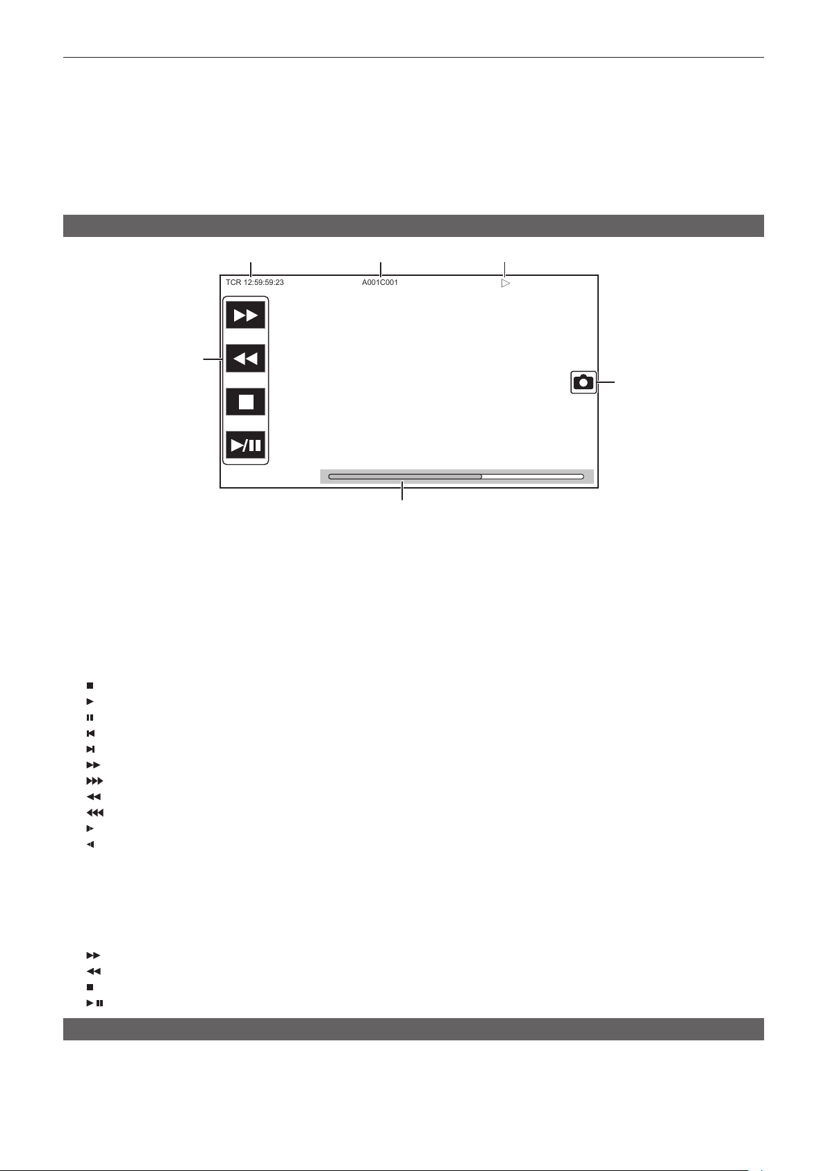
– 159 –
Chapter 5 Shooting — Display of the viewnder status
f [1080-59.94p]
f [1080-50.00p]
f [1080-29.97p]
f [1080-25.00p]
f [1080-23.98p]
f [1080-59.94i]
f [1080-50.00i]
f [720-59.94p]
f [720-50.00p]
Screen display during playback
TCR 12:59:59:23
A001C001
3
5
6
1 2
4
1 Time code display
Displays the time data selected with the <DISPLAY> switch.
f [TCR **:**:**:**]: Displays the time code.
f [UBR ** ** ** **]: Displays the user bits.
f [CLP **:**:**:**]: Displays the counter value of the clip being played back.
2 Clip name
Displays the name of the clip being played back with up to eight characters from the start.
3 Playback status
Displays the status of playback.
Displays only during playback.
f
: Stop
f
: Playback
f
: Pause
f
: Starting playback position
f
: Ending playback position
f
: Fast-forward playback (10x speed)
f
: Fast-forward playback (20x speed)
f
: Fast-reverse playback (10x speed)
f
: Fast-reverse playback (20x speed)
f
: Slow playback/frame-by-frame
f
: Reverse slow playback/frame-by-frame rewind
4 Still picture recording icon
Touching the icon while playing back or while paused records the scene as a still picture.
5 Direct playback bar
Displays the general position that is being played back.
6 Playback navigation icon
Operates by touching the icon.
f
: Fast-forward playback
f
: Fast-reverse playback
f
: Stop
f
/ : Playback/pause
Checking and displaying shooting status
Setting and status of each function is always displayed in the camera image screen but they can be set to be displayed only when required.
Most of the set values and status will not be displayed when the [VIDEO OUT/LCD/VF] menu → [INDICATOR] → [INDICATOR SW] → [OFF] is
selected.

– 160 –
Chapter 5 Shooting — Display of the viewnder status
When there is a need to conrm, push the <MARKER SEL>/<MODE CHECK> towards the <MCK> side while the camera image screen is displayed to
display the STATUS screen of the mode check which show the shooting status.
For details about each item that can be displayed in the mode check, refer to “Mode check display” (page 161).
The following table indicates each item to display/hide in each screen.
f “l” indicates displaying and “—” indicates hiding.
f You can select to display or hide each item in the [VIDEO OUT/LCD/VF] menu → [INDICATOR].
Conrm the display position during playback with the corresponding numbers in “Screen display during shooting” (page 154)
No Display item name Menu item and selection of display/hide
Switching display/hide in
the normal screen
Playback
screen
STATUS
[INDICATOR SW]
[ON] [OFF]
1 Time code/User bits/Counter
data
[TC]
l l
—
l*
1
l
2 Bonding Device Status [BONDING DEVICE]
l l
— —
l
3 Recording status [REC STATUS]
l l l*
2
—
l
4 Recording media [REC MEDIA]
l l
— —
l
5 Status of the card slot 1 or 2*
3
[SLOT STATUS]
l l
—*
4
—
l
6 Remaining capacity and status
of the memory card in card
slot 1 or 2*
3
[SLOT STATUS]
l l
—*
4
—
l
7 Message display area for
wireless audio warning and
cooling fan stop
[AUDIO] menu → [INPUT
SETTINGS] → [WIRELESS
WARN]
l l l
—
l
Fan stop message —
l l l l
8 SDI/HDMI remote control
status
[REC REMOTE]
l l
— —
l
9 Status of card slot 3 [SLOT STATUS]
l l
—*
4
—
l
10 Remaining capacity and status
of the memory card in card
slot 3
[SLOT STATUS]
l l
—*
4
—
l
11 Special recording function [REC MODE]
l l
— —
l
12 Two-slot function [2 SLOTS FUNC.]
l l
— —
l
[NDI|HX]
— —
Playback status [PLAYBACK STATUS]
l
— —
l*
1
—
13 Flash band compensation
function
[FBC1] or [FBC2]
l l
— —
l
14 Streaming status [STREAMING]
l l
— —
l
15 High dynamic range function/
dynamic range stretcher
function/V-Log recording
function
[HDR/DRS/V-Log]
l l
— —
l
16 Connection status of the wired
LAN, wireless LAN, and USB
tethering
[NETWORK]
l l
— —
l
17 Remaining battery level [BATTERY REMAIN]
l l
—*
4
—
l
18 Chromatic aberration
compensation function
[CAC]
l l
— —
l
19 Gamma mode [GAMMA MODE]
l l
— —
l
20 Scene le name [SCENE FILE]
l l
— —
l
21 Upload status display —
l l
— —
l
22 Waveform monitor Changing by USER switch —
l l
— —
23 Type of marker — — — — —
l
24 Digital zoom [D.ZOOM]
l l
— —
l
25 Focus [ZOOM/FOCUS]
l l
— —
l
26 Zoom [ZOOM/FOCUS]
l l
— —
l
27 Super black [IRIS]
l l
— —
l
28 Iris [IRIS]
l l
—*
5
—
l
29 Super iris [IRIS]
l l
— —
l
30 High-sensitivity mode [SHOOTING MODE]
l l
— —
l
31 Iris override [IRIS]
l l
—*
5
—
l
32 Luminance drop message
display
— —
l l
—
l
33 Luminance of Y GET — —
l l
—
l
34 Shutter speed [SHUTTER]
l l
— —
l
35 Date and time information [DATE/TIME]
l l
— —
l
36 Digital super gain [GAIN]
l l
— —
l
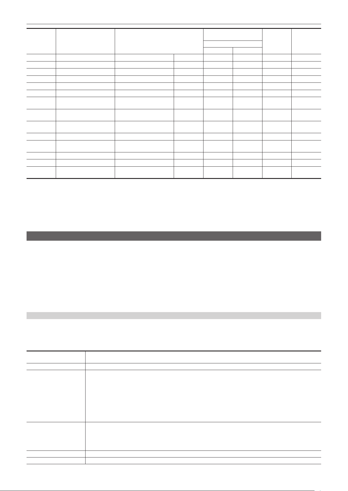
– 161 –
Chapter 5 Shooting — Display of the viewnder status
No Display item name Menu item and selection of display/hide
Switching display/hide in
the normal screen
Playback
screen
STATUS
[INDICATOR SW]
[ON] [OFF]
37 Gain [GAIN]
l l
— —
l
38 Auto knee — — — — —
l
39 Color temperature [WHITE BALANCE]
l l
—*
6
—
l
40 Audio level meter [AUDIO LEVEL METER]
l l
— —
l
41 Filter position [FILTER]
l l
— —
l
42 Extender [EXTENDER]
l l
— —
l
43 Remote control status in an IP
connection
— — — — —
l
44 Error display of auto black
balance
— — — — —
l
45 Error display of auto white
balance
— — — — —
l
46 Message display area — —
l l l l
47 Message for invalid lter
position
— —
l l
—
l
48 Clip name [CLIP NAME]
l l
—
l*
1
*
7
l
49 Recording format [REC FORMAT]
l l
— —
l
50 System resolution/system
frequency
[REC FORMAT]
l l
— —
l
*1 Not displayed when the [VIDEO OUT/LCD/VF] menu → [INDICATOR] → [INDICATOR SW] → [OFF] is selected.
*2 Only [REC] is displayed.
*3 Status of the card slot 1 is displayed when the [RECORDING] menu → [REC MEDIA] is set to [expressP2], and the status of the card slot 2 is displayed when
set to [microP2/SD].
*4 Displayed when the remaining capacity of the memory card or remaining battery level gets low.
*5 Displayed when the setting value of the iris override function is changed.
*6 Displayed when the color temperature is changed with color temperature change function.
*7 The display position differs in the playback screen. For details, refer to “Screen display during playback” (page 159).
Mode check display
The camera settings and status can be displayed on the viewnder or LCD monitor screen for check.
Mode check STATUS screen is displayed when the <MARKER SEL>/<MODE CHECK> switch is pushed towards the <MCK> side when camera image
screen is displayed.
Every time the <MARKER SEL>/<MODE CHECK> switch is pressed to the <MCK> side, display is switched in the order of STATUS screen, !LED
screen, FUNCTION screen, AUDIO screen, CAC screen, SWITCH screen, NETWORK screen, and camera image screen.
Each screen of the mode check is displayed for approximately ve seconds.
The screen does not switch while the <MARKER SEL>/<MODE CHECK> button is being pressed to the <MCK> side.
Press the <EXIT> button while each screen is displayed to return to the camera image screen.
[ON]/[OFF] display in each screen can be selected in the [VIDEO OUT/LCD/VF] menu → [MODE CHECK INDICATOR].
For details on STATUS screen displays, refer to “Checking and displaying shooting status” (page 159).
!LED screen
Displays the items to cause the [!] lamp of the viewnder to illuminate.
f [!] is displayed for items set to [ON] in the [VIDEO OUT/LCD/VF] menu → [!LED].
f [!] is displayed with black and white inverted when an item, to which [ON] is set in the [VIDEO OUT/LCD/VF] menu → [!LED], is cause of [!] lamp to be
illuminated.
[GAIN(0dB)]
Displays the gain status.
[AGC] is displayed when the [CAMERA] menu → [AGC] → [AGC] → [ON] is set.
[DS.GAIN] Displays the digital super gain value.
[SHUTTER]
Displays the shutter status.
f [1/****]: Displays the shutter speed.
f [w1/*****]: Displays the shutter speed in time (minutes) when synchro scan function is enable and the [SCENE FILE]
menu → [SYNC SCAN TYPE] → [sec] is set.
f [w*****d]: Displays the shutter speed in open angle when synchro scan function is enable and the [SCENE FILE] menu
→ [SYNC SCAN TYPE] → [deg] is set.
f [HALF]: Displays when the [CAMERA] menu → [SHUTTER SPEED] → [POSITION1] to [POSITION6] → [HALF] is set and the
position is selected.
f [OFF]: Shutter function is disabled.
[WHITE PRE.]
Displays the white balance status.
Displays the position selected with the <WHITE BAL> switch or the following.
f [ATW]: Displayed when the auto tracking white balance is operating. Flashes when luminance level and color temperature are
outside the range.
f [LOCK]: Displayed when the auto tracking white balance is locked.
[EXTENDER] Displays the status of the extender.
[B.GAMMA] Displays the status of black gamma.

– 162 –
Chapter 5 Shooting — Display of the viewnder status
[MATRIX] Displays the currently selected color correction table.
[COLOR COR.] Displays the status of the color correction function.
[FILTER] Displays the <ND FILTER> dial position with numbers 1 to 4 and <CC FILTER> dial position with alphabet A to D.
[ATW] Displays the status of automatic tracking white balance.
FUNCTION screen
Displays the video output settings and information of the recording media.
Item Description
[VIDEO OUT] [SDI OUT1 FORMAT]
Format set in the [VIDEO OUT/LCD/VF] menu → [SDI OUT1] → [OUT
FORMAT] is displayed.
[SDI OUT1 CHAR]
Setting of the [VIDEO OUT/LCD/VF] menu → [SDI OUT1] → [SDI OUT CHAR]
is displayed.
[SDI OUT2 FORMAT]
Format set in the [VIDEO OUT/LCD/VF] menu → [SDI OUT2] → [OUT
FORMAT] is displayed.
[SDI OUT2 CHAR]
Setting of the [VIDEO OUT/LCD/VF] menu → [SDI OUT2] → [SDI OUT CHAR]
is displayed.
[HDMI OUT SIGNAL]
Setting of the [VIDEO OUT/LCD/VF] menu → [HDMI OUT] → [SIGNAL SEL] is
displayed.
[HDR/SDR]
(When the [SYSTEM] menu →
[COLOR SETTING] → [NORMAL]
is set)
[SDI OUT1] The output image from the <SDI OUT1> terminal is displayed with [HDR]/
[SDR].
[SDI OUT2] The output image from the <SDI OUT2> terminal is displayed with [HDR]/
[SDR].
[HDMI OUT] The output image from the <HDMI> terminal is displayed with [HDR]/[SDR].
[LCD/VF] Displays the output image from the LCD monitor and the viewnder with [HDR]/
[SDR].
[V-Log]/[V-709]
(When the [SYSTEM] menu →
[COLOR SETTING] → [V-Log] is set)
[SDI OUT1] The output image from the <SDI OUT1> terminal is displayed with [V-Log]/
[V-709].
[SDI OUT2] The output image from the <SDI OUT2> terminal is displayed with [V-Log]/
[V-709].
[HDMI OUT] The output image from the <HDMI> terminal is displayed with [V-Log]/[V-709].
[LCD/VF] Displays the output image from the LCD monitor and the viewnder with
[V-Log]/[V-709].
[CARD STATUS] [TOTAL]
Displays the setting status of the [RECORDING] menu → [REC MEDIA], and
remaining capacity (minutes)/total recording time of the memory card to record
on.
Displays the information of the card slot 1 when the [RECORDING] menu →
[REC MEDIA] is set to [expressP2] and total of card slots 2 and 3 when set to
[microP2/SD].
It is not displayed when the [NETWORK] menu → [NETWORK FUNC] is set to
[NDI|HX].
[SLOT1] Displays the remaining capacity (%)/remaining capacity (minutes)/total
recording time of the memory card inserted in card slot 1.
It is not displayed when set to the [NETWORK] menu → [NETWORK FUNC] →
[NDI|HX].
The status of the memory card that is displayed are following types.
f [NO CARD]: Memory card is not inserted.
f [UNSUPPORTED]: Memory card is not supported.
f [FORMAT ERROR]: Memory card cannot be used. (Format error)
f [PROTECTED]: It is write protected. The write-protected switch of the
memory card is set to the Protect side.
f [NO REMAIN]: Memory card has no remaining capacity.
f [ENCRYPTED]: expressP2 card formatted with encryption with CPS
password is inserted.
In cases other than above, the remaining capacity of the memory card is
displayed in 0% through 100%.

– 163 –
Chapter 5 Shooting — Display of the viewnder status
Item Description
[SLOT2] Displays the remaining capacity (%)/remaining capacity (minutes)/total
recording time of the memory card inserted in card slot 2.
It is not displayed when set to the [NETWORK] menu → [NETWORK FUNC] →
[NDI|HX].
The status of the memory card that is displayed are following types.
f [NO CARD]: Memory card is not inserted.
f [UNSUPPORTED]: Memory card is not supported.
f [FORMAT ERROR]: Memory card cannot be used. (Format error)
f [PROTECTED]: It is write protected. The write-protected switch of the
memory card is set to the LOCK side.
f [NO REMAIN]: Memory card has no remaining capacity.
f [NOT SDXC]: Recording mode is set to MOV but SDXC memory card or
64 GB microP2 card is not inserted.
f [ENCRYPTED]: microP2 card formatted with encryption with CPS password
is inserted.
In cases other than above, the remaining capacity of the memory card is
displayed in 0% through 100%.
[SLOT3] Displays the remaining capacity (%)/remaining capacity (minutes)/total
recording time of the memory card inserted in card slot 3.
It is not displayed when set to the [NETWORK] menu → [NETWORK FUNC] →
[NDI|HX].
The status of the memory card that is displayed are following types.
f [NO CARD]: Memory card is not inserted.
f [UNSUPPORTED]: Memory card is not supported.
f [FORMAT ERROR]: Memory card cannot be used. (Format error)
f [PROTECTED]: It is write protected. The write-protected switch of the
memory card is set to the LOCK side.
f [NO REMAIN]: Memory card has no remaining capacity.
f [NOT SDXC]: Recording mode is set to MOV but SDXC memory card or
64 GB microP2 card is not inserted.
f [ENCRYPTED]: microP2 card formatted with encryption with CPS password
is inserted.
In cases other than above, the remaining capacity of the memory card is
displayed in 0% through 100%.
AUDIO screen
Displays the audio input/output settings and the recording level.
Item Description
[MIC POWER(MENU)]
Displays the setting value of the [AUDIO] menu → [INPUT SETTINGS] →
[FRONT MIC POWER] and the [AUDIO] menu → [INPUT SETTINGS] →
[REAR MIC POWER].
[VOL. SELECT]
Displays the setting value of the [AUDIO] menu → [REC CH SETTINGS] →
[VOL. SELECT].
[A.IN] [CH1] to [CH4] Displays the audio input signal selected with the <AUDIO IN CH1> to <AUDIO
IN CH4> switches.
[LEVEL] [CH1] to [CH4] Displays the recording level adjustment method of each channel.
f [AUTO]: Automatic adjustment
f [VOL.]: Manually adjusted by the <AUDIO LEVEL CH1/3>/<AUDIO LEVEL
CH2/4> dial
f [MENU]: Manually adjusted by the [AUDIO] menu → [REC CH SETTINGS]
→ [CH1 LEVEL CONTROL] to [CH4 LEVEL CONTROL]
[F.VOL.] [CH1] to [CH4] Displays whether the <F.AUDIO LEVEL> dial is enabled in each channel.
f [ON]: Enabled
f [OFF]: Disabled
Settings in the <AUDIO IN CH1> to <AUDIO IN CH4> switch and the
[AUDIO] menu → [REC CH SETTINGS] → [FRONT VOL. CH1] to [FRONT
VOL. CH4] does not match.
f [---]: Disabled
The channel is not selected in the [AUDIO] menu → [REC CH SETTINGS] →
[VOL. SELECT].
[LIMITER] [CH1] to [CH4] Displays enable/disable of limiter for each channel with [ON]/[OFF].
Displays [---] when recording level adjustment method is automatic adjustment.
[LOWCUT] [CH1] to [CH4] Displays enable/disable of low-cut lter for each channel with [ON]/[OFF].
CAC screen
Displays information about the chromatic aberration compensation function.
[CAC CONTROL]
Displays the setting value of the [CAMERA] menu → [CAC ADJ.] → [CAC CONTROL].
[STOP] is displayed when the chromatic aberration compensation function is not active due to conditions of the data or
the lens even if set to the [CAMERA] menu → [CAC ADJ.] → [CAC CONTROL] → [ON].
[CAC MODE] Displays the operation mode of the chromatic aberration compensation function.
f [AUTO]: The CAC le is automatically selected.
– 164 –
Chapter 5 Shooting — Display of the viewnder status
[CONNECT LENS TYPE] Displays the lens ID of the currently connected digital lens.
[SELECT FILE TITLE] Displays the title and the le version of the CAC le currently used for chromatic aberration compensation.
[CAC WARNING] Displays a warning when operation of the chromatic aberration compensation has stopped.
f [CAC LENS DATA INVALID]: This is displayed, for example, when the response data from the lens is not supported.
f [LENS INITIALIZATION NOT COMPLETED]: This is displayed, for example, when initialization of the lens cannot be
completed.
SWITCH screen
Displays the function assigned to the USER button, <GAIN> switch, and <WHITE BAL> switch as well as the setting value.
Item Description
[USER SW] [1] to [5] Displays the function assigned to the <USER 1> through <USER 5> buttons.
[OTHER ASSIGN] [RET SW] Displays the function assigned to the <RET> button of the lens.
[GAIN L] Displays the gain value assigned to <L> of the <GAIN> switch.
[GAIN M] Displays the gain value assigned to <M> of the <GAIN> switch.
[GAIN H] Displays the gain value assigned to <H> of the <GAIN> switch.
[S.GAIN] Displays the list of gain values assigned as a super gain.
[DS.GAIN] Displays the gain value assigned as digital super gain. [ALL] is displayed when
the [CAMERA] menu → [USER SW GAIN] → [DS.GAIN] → [ALL] is set.
[WHITE BAL A] Displays the color temperature assigned to <A> of the <WHITE BAL> switch.
Displays [ATW] when the auto tracking white balance function is assigned.
[WHITE BAL B] Displays the color temperature assigned to <B> of the <WHITE BAL> switch.
Displays [ATW] when the auto tracking white balance function is assigned.
[WHITE BAL PRST] Displays the color temperature assigned to <PRST> of the <WHITE BAL>
switch.
Displays [ATW] when the auto tracking white balance function is assigned.
Color temperature and [VAR] are displayed when [VAR] is assigned.
NETWORK screen
Displays the settings of the network function.
Item Description
[NETWORK] [DEVICE SEL]
Displays the setting value of the [NETWORK] menu → [DEVICE SEL].
[NETWORK FUNC]
Displays the setting value of the [NETWORK] menu → [NETWORK FUNC].
[STRM FORMAT] Displays the streaming format.
It is not displayed when set to the [NETWORK] menu → [NETWORK FUNC]
→ [OFF].
[STRM DATA TYPE]
Displays the setting value of the [NETWORK] menu → [STREAMING] → [DATA
TYPE].
It is not displayed when set to anything other than the [NETWORK] menu →
[NETWORK FUNC] → [STREAMING].
[IP REMOTE] Displays enable/disable status of the IP remote function.
[IPv4 ADDRESS] Displays the IP address of IPv4.
It is not displayed when set to the [NETWORK] menu → [DEVICE SEL] →
[OFF].
[IPv6 ADDRESS] Displays the IP address of IPv6.
[DISABLE] is displayed when the [NETWORK] menu → [LAN PROPERTY] →
[IPv6 SETTING] → [ENABLE/DISABLE] → [DISABLE] is set.
It is not displayed when set to anything other than the [NETWORK] menu →
[DEVICE SEL] → [LAN].
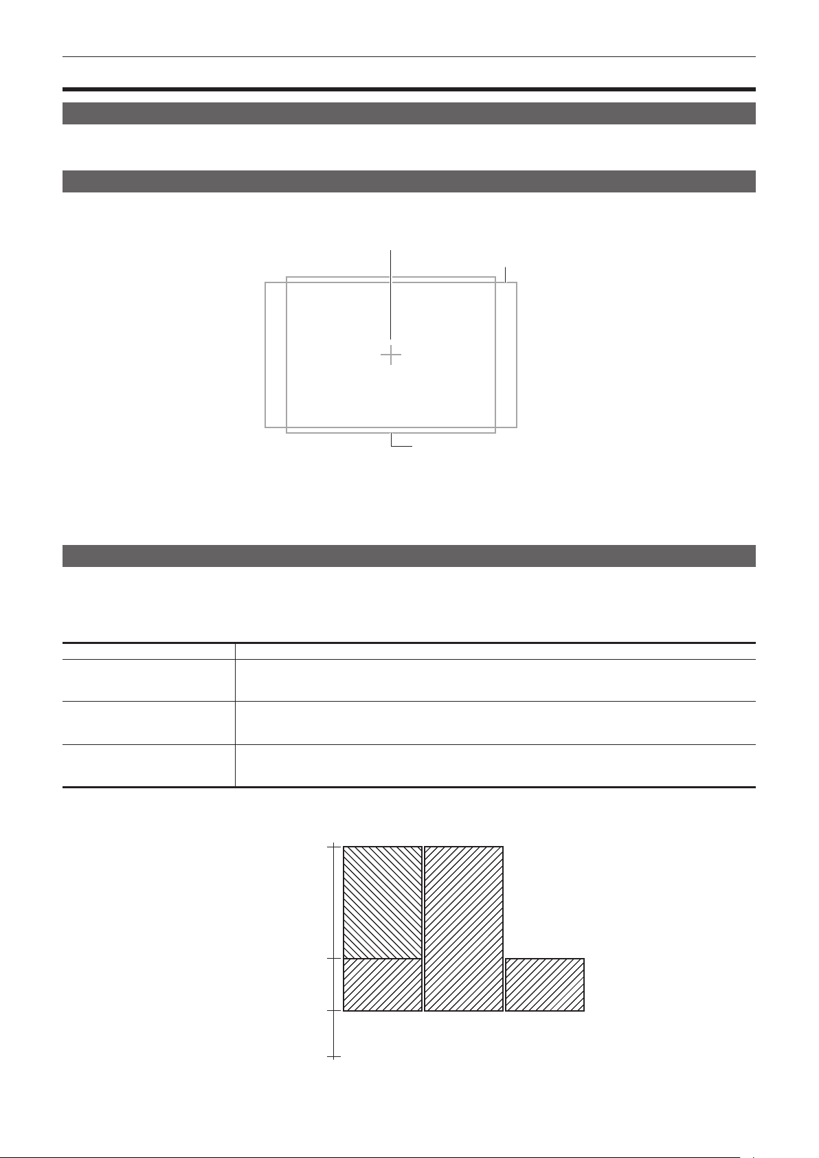
– 165 –
Chapter 5 Shooting — Convenient shooting functions
Convenient shooting functions
Setting the marker display
Select the type and display of the center marker, safety zone marker, safety zone area, and frame marker.
Set marker display in each item in the [VIDEO OUT/LCD/VF] menu → [SDI OUT1 MARKER]/[SDI OUT2 MARKER]/[LCD/VF MARKER].
Marker conrmation screen (marker select function)
Displays the screen for conrming the marker status of the camera is displayed on the viewnder screen.
Type of marker
Center marker
Safety zone
Frame marker
Pushing the <MARKER SEL>/<MODE CHECK> switch on the camera towards the <MKR> side switches the marker on the viewnder in the order of
[A] marker, [B] marker, and no display.
Aspect ratios 14:9 and 4:3 can be conrmed by using the <MARKER SEL>/<MODE CHECK> switch when set to the following.
f Set [MKR:A] as the [VIDEO OUT/LCD/VF] menu → [LCD/VF MARKER] → [FRAME MARKER] → [14:9].
f Set [MKR:B] as the [VIDEO OUT/LCD/VF] menu → [LCD/VF MARKER] → [FRAME MARKER] → [4:3].
Displaying zebra pattern
The camera can display two types of zebra patterns.
When the <ZEBRA> switch of the viewnder is set to <ON>, the zebra pattern currently set in the menu is displayed on the viewnder screen.
Zebra patterns can also be displayed in the video output from <SDI OUT1>/<SDI OUT2>/<HDMI> terminals according to settings.
The level for displaying zebra patterns can be set in the [VIDEO OUT/LCD/VF] menu → [EI ASSIST].
Item Description of settings
[ZEBRA1 DETECT]
Sets the level of zebra pattern 1 tilting to the right.
f [0%]…[109%]
(Factory setting: [80%])
[ZEBRA2 DETECT]
Sets the level of zebra pattern 2 tilting to the left.
f [0%]…[109%]
(Factory setting: [100%])
[ZEBRA2]
Selects the type of [ZEBRA2].
f [ON], [SPOT], [OFF]
(Factory setting: [OFF])
[SPOT]: The image level from the setting value of [ZEBRA1 DETECT] to the setting value of [ZEBRA2 DETECT] is displayed in the zebra pattern.
[ZEBRA2]
Image level
[ON] [OFF] [SPOT]
[109%]
[ZEBRA2 DETECT]
[ZEBRA1 DETECT]
[0%]
When displaying the zebra pattern in the video output from <SDI OUT1> and <SDI OUT2> terminals, perform setting in the [VIDEO OUT/LCD/VF] menu
→ [SDI OUT1]/[SDI OUT2] → [SDI OUT ZEBRA].
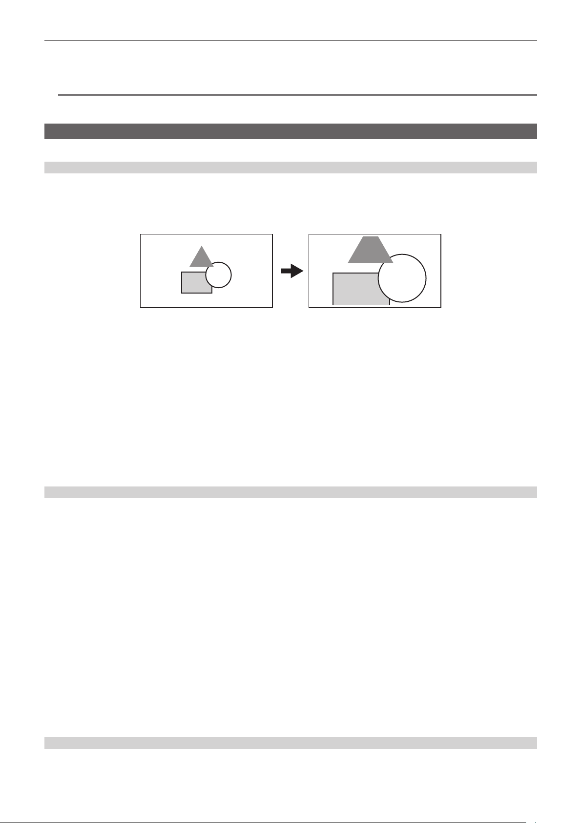
– 166 –
Chapter 5 Shooting — Convenient shooting functions
Display of zebra pattern output to the <HDMI> terminal is based on the following setting.
f [VIDEO OUT/LCD/VF] menu → [HDMI OUT] → [SIGNAL SEL]
f [VIDEO OUT/LCD/VF] menu → [SDI OUT1]/[SDI OUT2] → [SDI OUT ZEBRA]
@
NOTE
t The zebra pattern is not displayed when the [SCENE FILE] menu → [GAMMA MODE SEL] → [HLG] is selected.
t The zebra pattern is not displayed when the [SYSTEM] menu → [COLOR SETTING] → [V-Log] is set.
Focus assist function
The focus assist function enables you to focus the target easily.
Enlarged display
r Assigning [FOCUS ASSIST] to the USER button
Assigns [FOCUS ASSIST] to the desired USER button or <RET> button on the lens.
Pressing the assigned USER button enlarges the center of the screen and make it easier to focus when the [VIDEO OUT/LCD/VF] menu → [FOCUS
ASSIST] → [FOCUS ASSIST SELECT] → [EXPAND] is selected.
r Setting the mode for enlarged display function
The method to cancel the enlarged display can be selected in the [VIDEO OUT/LCD/VF] menu → [FOCUS ASSIST] → [EXPAND MODE].
When using peaking display and focus square display simultaneously, they may be disabled depending on the setting of the enlarged display.
[10SEC]: Cancels in 10 seconds.
[HOLD]: Cancels when the button to which [FOCUS ASSIST] is assigned is pressed.
[UNTIL REC]: Cancels when recording starts. Enlarged display is not available during recording.
r Setting the enlargement rate
Can be selected from the [VIDEO OUT/LCD/VF] menu → [FOCUS ASSIST] → [EXPAND VALUE] → [×2]/[×3]/[×4].
r Setting the enlargement position
The enlargement position can be selected from nine positions when the enlarged display function is enabled.
In the case of the jog dial button: Turn the jog dial button to move the enlarged position. It will return to center when the jog dial button is pressed.
It can also be operated by pressing the cursor operation button.
In case of touching the LCD monitor: The enlarged position will move by touching the vertical and horizontal arrow markers on the LCD monitor.
Peaking display/focus square display
The peaking display will outline the contour of the focused image in red, green, or white.
The degree of focus is indicated by the size of the square in the focus square display.
r Displaying the peaking display/focus square display
Assigns [FOCUS ASSIST] to the desired USER button or <RET> button on the lens.
Select the [VIDEO OUT/LCD/VF] menu → [FOCUS ASSIST] → [FOCUS ASSIST SELECT] → [PEAKING]/[SQUARES] and press the USER button
assigned with [FOCUS ASSIST] to display in the set type. Press the USER button again to return to the normal display.
r Setting the focus assist display type
Select the type of display in the [VIDEO OUT/LCD/VF] menu → [FOCUS ASSIST] → [FOCUS ASSIST SELECT].
[EXPAND]: Sets the enlarged display.
[PEAKING]: Sets the peaking display.
[SQUARES]: Sets the focus square display.
[EXPAND+PEAKING]: Displays in combination of [EXPAND] and [PEAKING].
[EXPAND+SQUARES]: Displays in combination of [EXPAND] and [SQUARES].
r Setting the peaking level
Sets the intensity of the peaking display.
Can be selected from the [VIDEO OUT/LCD/VF] menu → [FOCUS ASSIST] → [PEAKING LEVEL] → [LOW]/[MID]/[HIGH].
r Setting the color for peaking display
Can be selected from the [VIDEO OUT/LCD/VF] menu → [FOCUS ASSIST] → [PEAKING COLOR] → [RED]/[GREEN]/[WHITE].
How to use the focus square display
Adjust focus so that the size of the square shown over the desired subject to focus on becomes the largest size.

– 167 –
Chapter 5 Shooting — Convenient shooting functions
Monochrome display
Enables/disables the monochrome display in the [VIDEO OUT/LCD/VF] menu → [FOCUS ASSIST] → [BLACK & WHITE].
[ON]: Enables the monochrome display.
[OFF]: Disables the monochrome display.
[DURING PEAKING]: Enables the monochrome display while the peaking display is enabled.
Highlighting the contours of images
It is easier to focus if the contours of images on the LCD monitor and viewnder are highlighted.
Highlighting contours does not affect the images output or recorded by the camera.
Highlights the contours of images when set to the [VIDEO OUT/LCD/VF] menu → [FOCUS ASSIST] → [DETAIL] → [ON].
Intensity of the contour can be adjusted in the [VIDEO OUT/LCD/VF] menu → [FOCUS ASSIST] → [DETAIL] → [DETAIL LEVEL].
Frequency of the contour can be adjusted in the [VIDEO OUT/LCD/VF] menu → [FOCUS ASSIST] → [DETAIL] → [DETAIL FREQ.].
@
NOTE
t The enlarged display/peaking display/focus square display cannot be recorded.
t The enlarged display/peaking display/focus square display is not displayed while displaying the color bars.
t Some of the displays such as marker will be hidden temporarily during enlarged display/focus square display.
Waveform monitor function
Pressing the USER buttons to which [WFM] is assigned will display the waveform of the image. Press the USER button again to return to the normal
display.
f The waveform and vector displays can be switched by the [VIDEO OUT/LCD/VF] menu → [EI ASSIST] → [WFM MODE]. (page 96)
f The waveform monitor is not displayed during enlarged display or focus square display of the focus assist function.
f The waveform monitor cannot be recorded.
f The waveform monitor is automatically displayed when some of the menus to perform the image quality adjustment are set.

– 168 –
Chapter 5 Shooting — Adjusting and setting the LCD monitor
Adjusting and setting the LCD monitor
Using the LCD monitor
1
Push the <OPEN> button towards the right to open the LCD monitor.
2
Set the LCD monitor screen to the easiest-to-view position.
Rotate up to 180° in the lens direction and 90° in the direction towards you.
3
Adjust the brightness of the LCD monitor/color density/contrast/brightness of the back light in the [VIDEO OUT/LCD/VF] menu →
[LCD] → [BRIGHTNESS]/[COLOR LEVEL]/[CONTRAST]/[BACK LIGHT].
Brightness of the back light can be adjusted by pressing the USER button assigned with [LCD BACKLIGHT].
@
NOTE
t When closing the LCD monitor, be sure to close it rmly.
t Take care not to apply excessive force on the LCD monitor when it is opened. Doing so may result in a malfunction.
t Condensation sometimes forms on the LCD panel of the LCD monitor in locations subject to extreme temperature differences. If this happens, wipe
with a soft, dry cloth.
t The LCD monitor will be slightly darker than normal immediately after the power is turned on when the camera is very cold. The brightness will return
to normal when the internal temperature increases.
Mirror shooting
When recording with the LCD monitor rotated 180° to the lens side, if the camera is set to the [VIDEO OUT/LCD/VF] menu → [LCD] → [SELF SHOOT]
→ [MIRROR], the image is displayed in reverse in left and right on the LCD monitor. This allows shooting as if looking at a mirror image. Note that only
the display of the LCD monitor is horizontally reversed. Recording is performed as per normal.
@
NOTE
t When the LCD monitor is rotated 180° with the [VIDEO OUT/LCD/VF] menu → [LCD] → [SELF SHOOT] → [MIRROR] selected, the same state as in
the viewnder is not displayed in the LCD monitor regardless of the setting in the [VIDEO OUT/LCD/VF] menu → [INDICATOR].

– 169 –
Chapter 5 Shooting — Adjusting and setting the viewnder
Adjusting and setting the viewnder
Using the viewnder
For details about the attachment to the camera and adjustment, refer to the Operating Instructions for each viewnder. Set the items of the [VIDEO
OUT/LCD/VF] menu to specify the information to display in the viewnder.
For details on method of use, refer to the Operating Instructions for each viewnder.
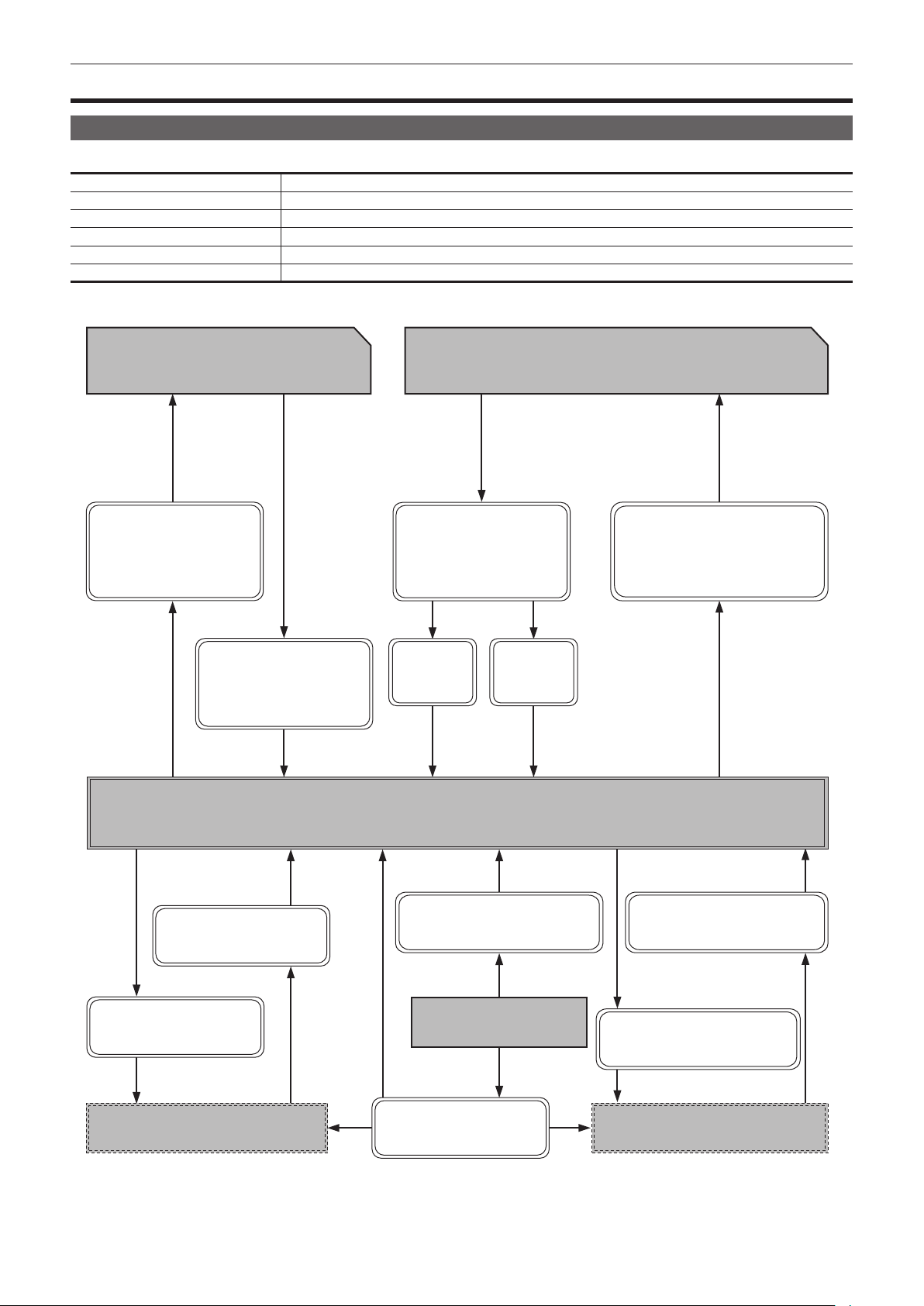
– 170 –
Chapter 5 Shooting — Handling setting data
Handling setting data
File structure of the setting data
The camera has six le data areas.
Factory data This area stores factory settings. It cannot be rewritten by menu operation.
Current data This area stores the operation status of the camera. Setting values in this area are changed by menu operation.
Setup le This area stores values set by menu operation. As default data, factory data is stored here.
Scene le Six scene les are provided.
Lens les Eight lens les are provided. Eight of these les can be saved together as a single le on SD card.
CAC le This area stores 32 chromatic aberration compensation data.
r Setup le and scene le
Number of files: 1
Number of files: 6
Factory data
Scene file (memory)
Setup file (memory)
[OTHERS] → [FILE] → [SETUP
FILE(MEMORY)] → [LOAD]
[SCENE FILE] →
[LOAD/SAVE/INITIALIZE] → [SAVE]
[SCENE FILE] →
[LOAD/SAVE/INITIALIZE] →
[INITIALIZE]
[OTHERS] → [MENU
INITIALIZE]
[SCENE FILE] →
[LOAD/SAVE/INITIALIZE] → [LOAD]
[OTHERS] → [FILE] → [SETUP
FILE(MEMORY)] → [SAVE]
Current data
[OTHERS] → [FILE] → [SETUP
FILE(SD CARD)] → [LOAD]
[ALL]
[SCENE1] -
[SCENE6]
[OTHERS] → [FILE] → [SCENE
FILE(SD CARD)] → [LOAD]
[OTHERS] → [FILE] → [SCENE FILE
(SD CARD)] → [SAVE]/[SAVE AS]
[OTHERS] → [FILE] → [SETUP
FILE(SD CARD)] → [SAVE]/
[SAVE AS]
SD card
SD card
Scene file
Setup file
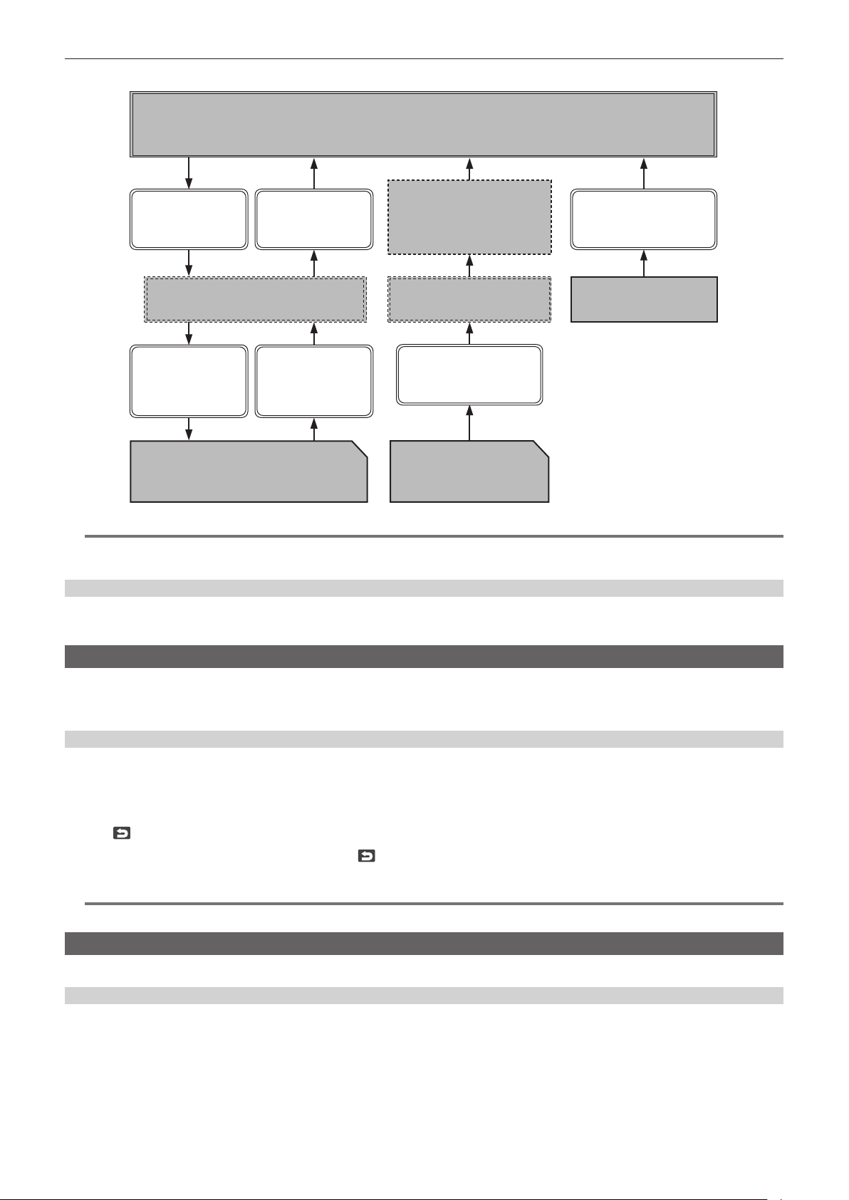
– 171 –
Chapter 5 Shooting — Handling setting data
r Lens le and CAC le
↓
↓
Factory data
[OTHERS] → [MENU
INITIALIZE]
SD card
SD card
CAC file
Lens files
[OTHERS] → [FILE] →
[LENS FILE(SD
CARD)] → [LOAD]
[OTHERS] → [FILE] →
[LENS FILE(SD
CARD)] → [SAVE]/
[SAVE AS]
[OTHERS] → [FILE] → [CAC
FILE(SD CARD)] → [LOAD]
Number of files: 32Number of files: 8
CAC file (memory)Lens file (memory)
[OTHERS] → [FILE] →
[LENS FILE
(MEMORY)] → [LOAD]
[OTHERS] → [FILE] →
[LENS FILE
(MEMORY)] → [SAVE]
Automatically load the file
matching with the lens
connected by [CAMERA] →
[CAC ADJ.] → [CAC CONTROL]
→ [ON]
Current data
@
NOTE
t Each le cannot be operated by displaying the menu during interval recording standby. Press the <REC> or <STOP> button to end interval recording,
and try the operation again.
Setting up using SD cards
An SD card can be used as a setup card that stores menu content.
Use of this data allows you to reproduce optimum setup states.
Operating SD cards
Select in the [OTHERS] menu → [FILE] → [SLOT FOR LOAD/SAVE] → [SLOT2]/[SLOT3].
If a SD card that was formatted in a standard other than SDHC/SDXC standards on a device other than this camera is inserted, le cannot be loaded or
saved. Reformat the SD card.
Formatting the SD card
1
Select the [RECORDING] menu → [FORMAT MEDIA] → [SLOT2]/[SLOT3].
Select the card slot where the SD card to format is inserted.
2
Select [SET] in the confirmation screen.
Select
when not formatting.
3
When the completion message is displayed, select
.
For details about the error message, refer to “Warning system” (page 227).
@
NOTE
t Data deleted as a result of formatting cannot be restored. Always conrm the data before formatting.
Setup le
Specied menu can be saved or loaded to/from the camera memory or a SD card.
Saving the setup le
Saves the current setting value of the camera into the camera memory or SD card.

– 172 –
Chapter 5 Shooting — Handling setting data
1/4
2
4
A S D F G H J K L
A-a Z X C V B N M BS
Q
W
E R T Y U I O P
Enter
123
#+=
FILE NAME
1
SETUP004
SETUP003
SETUP002
SETUP001
3
08:11:06
08:10:00
08:08:11
08:05:10
MENU>OTHERS>FILE>SETUP FILE(SD CARD)>SAVE
DEC-01-2019
DEC-01-2019
DEC-01-2019
DEC-01-2019
MENU>OTHERS>FILE>SETUP FILE(SD CARD)>SAVE AS
Fig. 1 Fig. 2
Saving a setup le as a new le on a SD card
Current setting values of the camera is saved as a new le in a SD card by specifying the le name.
1
Select the [OTHERS] menu → [FILE] → [SETUP FILE(SD CARD)] → [SAVE AS].
The le name entry screen and the keyboard are displayed. (Fig. 1)
2
Enter the text to set with the keyboard.
3
Select [Enter].
A conrmation screen is displayed.
4
Select [SET].
The le is saved.
Overwriting a setup le on SD card
Overwrites the le selected in the list of the setup les saved on the SD card with the current setting values of the camera.
1
Select [OTHERS] menu → [FILE] → [SETUP FILE(SD CARD)] → [SAVE].
The list of setup les saved on the SD card is displayed. (Fig. 2)
2
Select the file to overwrite from the list of setup files.
The le name entry screen and the keyboard are displayed. Leave it as is when overwriting.
3
Select [Enter].
A conrmation screen is displayed.
4
Select [SET].
The le is saved.
Saving the setup le to the camera memory
Saves the current setting value of the camera into the camera memory.
1
Select [OTHERS] menu → [FILE] → [SETUP FILE(MEMORY)] → [SAVE].
Loading the setup le
Loads a setup le from the camera memory or the SD card.
Loading the setup le from the SD card
Loads a setup le saved in the SD card.
1
Select the [OTHERS] menu → [FILE] → [SETUP FILE(SD CARD)] → [LOAD].
A list of setup les stored in the specied folder in the SD card is displayed.
2
Select the name of the file to load.
3
Select [SET].
Loading of the le is started. The camera is restarted after loading.
f An error message may be displayed. For error message, refer to “Warning system” (page 227).
f The le saved with different rmware version may not be able to load.
Loading setup les from the camera memory
Loads the setup le saved on the camera memory.
1
Select the [OTHERS] menu → [FILE] → [SETUP FILE(MEMORY)] → [LOAD].
Loading of the le is started. The camera is restarted after loading.
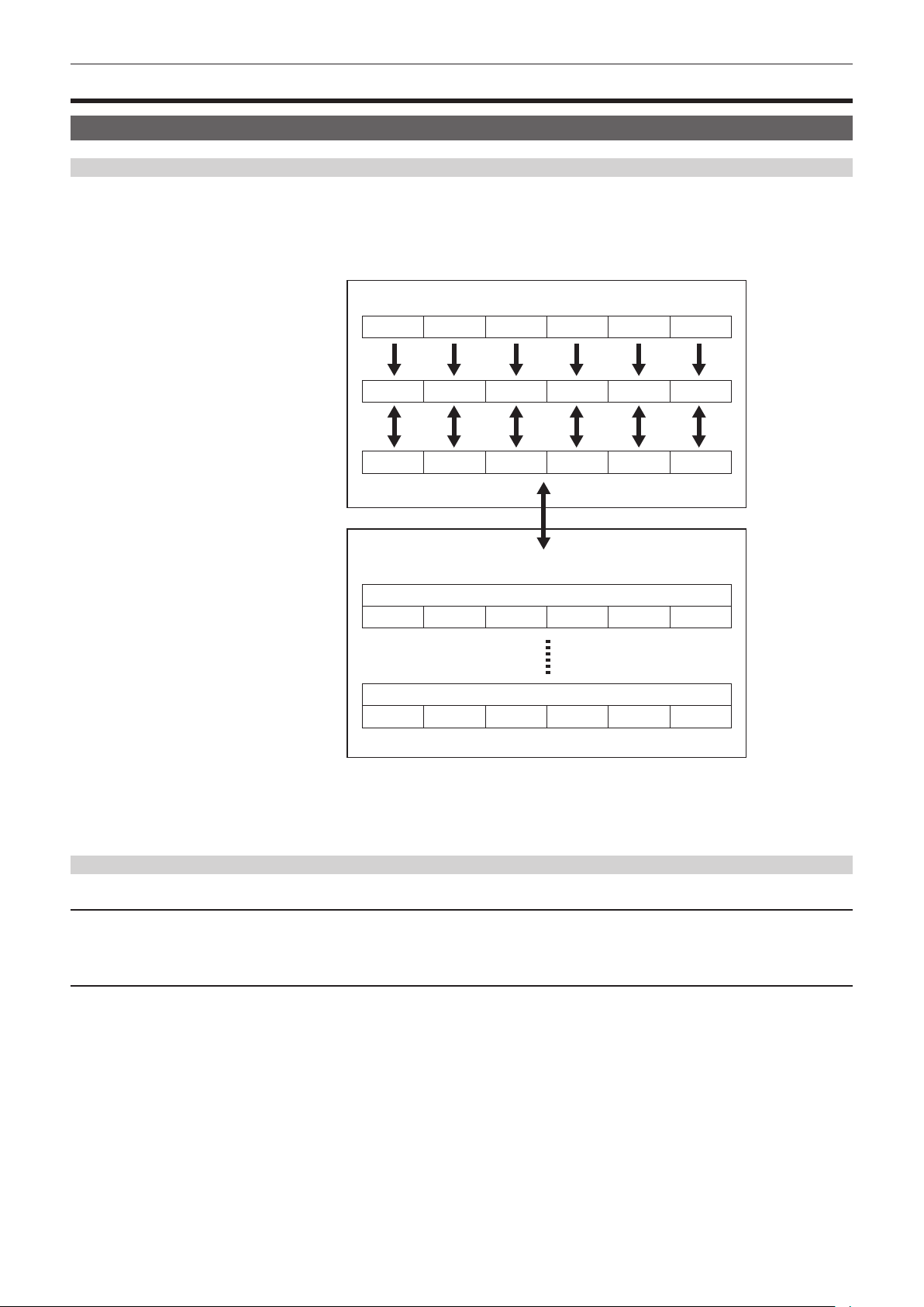
– 173 –
Chapter 5 Shooting — Scene le
Scene le
Scene les
File structure of the setting data
The scene les of [F1:] to [F6:] can be saved in the camera memory in accordance to the scene le number.
What can be saved as a scene le is the setting contents of the [SCENE FILE] menu.
In addition, the current setting values of the scene les of [F1:] to [F6:] can be saved as a le to the camera memory or a SD card, and that data can be
loaded and used in the camera.
Setting data le structure of the camera is as follows.
*1 *1 *1 *1 *1
*2 *2 *2 *2 *2
*1
*2
*3
(Factory setting)
The camera
(Current value)
(Value saved on the camera)
Memory card
Scene file 1
Scene file n
[F1:] [F2:] [F3:] [F4:] [F5:] [F6:]
[F6:]
[F6:]
[F6:]
[F6:]
[F1:] [F2:] [F3:] [F4:] [F5:]
[F1:] [F2:] [F3:] [F4:] [F5:]
[F1:] [F2:] [F3:] [F4:] [F5:]
[F1:] [F2:] [F3:] [F4:] [F5:]
*1 The scene le can be initialized.
Select the [SCENE FILE] menu → [LOAD/SAVE/INITIALIZE] → [INITIALIZE].
*2 Current setting value of each scene le can be individually saved in the camera body. Also, the scene les saved in the camera memory can be loaded.
Select the [SCENE FILE] menu → [LOAD/SAVE/INITIALIZE] → [LOAD]/[SAVE].
*3 The scene le can be saved in a SD card. Also, the scene le saved in the SD card can be loaded.
Saving the scene le
Saving the scene le into the camera memory
Saves the current setting value of the camera into the camera memory.
1
Select the [SCENE FILE] menu → [LOAD/SAVE/INITIALIZE] → [SAVE].
Saving the scene le to a SD card
The scene le can be overwritten to a le on the SD card, or saved as a new le.
r Saving a scene le as a new le on a SD card
Current setting values of the camera is saved as a new le in a SD card by specifying the le name.
1
Select the [OTHERS] menu → [FILE] → [SCENE FILE(SD CARD)] → [SAVE AS].
The le name entry screen and the keyboard are displayed.
2
Enter the text to set with the keyboard.
3
Select [Enter].
A conrmation screen is displayed.
4
Select [SET].
The le is saved.
f An error message may be displayed. For details about the error message, refer to “Warning system” (page 227).

– 174 –
Chapter 5 Shooting — Scene le
r Saving the scene le by overwriting a le on the SD card
Overwrites the le selected in the list of the scene les saved on the SD card with the current setting values of the camera.
1
Select the [OTHERS] menu → [FILE] → [SCENE FILE(SD CARD)] → [SAVE].
The list of scene les saved on the SD card is displayed.
2
Select the file to overwrite from the list of scene files.
The le name entry screen and the keyboard are displayed. Leave it as is when overwriting.
3
Select [Enter].
A conrmation screen is displayed.
4
Select [SET].
The le is saved.
Loading the scene le
The scene le saved in the camera memory or the SD card is loaded.
Loading the scene le from the camera memory
1
Select the [SCENE FILE] menu → [LOAD/SAVE/INITIALIZE] → [LOAD].
Loading the scene le from the SD card
1
Select the [OTHERS] menu → [FILE] → [SCENE FILE(SD CARD)] → [LOAD].
A list of scene les stored in the folder in the SD card is displayed.
2
Select the file name for the file to load.
3
Select either to load all scene files ([F1:] to [F6:]) or to load individually.
f To load all, select [ALL].
To load individually, select the scene number to load.
4
Select [SET].
The le is loaded.
f An error message may be displayed. For details about the error message, refer to “Warning system” (page 227).
Initialization of the scene le
Initializes the scene le saved in the camera memory.
1
Select the scene file to return to the factory setting in the [SCENE FILE] menu → [FILE SELECT].
2
Select the [SCENE FILE] menu → [LOAD/SAVE/INITIALIZE] → [INITIALIZE].
The conrmation screen is displayed.
3
Select [YES].
The selected scene le returns to the factory setting.
Changing the scene le name
Changes the name of the scene le saved in the camera memory.
Only changeable part is the title section of the scene le name. As an example, if the scene le name is [F6:HLG], only the “HLG” part can be changed.
1
Select the scene file to change the name in the [SCENE FILE] menu → [FILE SELECT].
2
Select the [SCENE FILE] menu → [NAME EDIT].
The le name entry screen and the keyboard are displayed.
3
Enter the text to set with the keyboard. (Maximum eight characters)
4
Select [Enter].
The le name is updated.
Returning the setting value of the menu to the factory setting
Most of the setting values of the menu can be returned to factory setting status.
Refer to “Target items for scene le/setup le/initialization” (page 116).
1
Select the [OTHERS] menu → [MENU INITIALIZE].
2
Select [SET] when the confirmation message is displayed.
Factory setting data is loaded.
@
NOTE
t Data saved as lens les in the camera memory are not deleted by performing this operation.

– 175 –
Chapter 5 Shooting — Scene le
Lens les
Eight lens les are stored to internal memory on the camera.
Eight lens les can be written into a SD card as a single card le.
The following data is recorded to lens les:
f Title name
f White shading compensation values
f Flare correction values
f RB gain offset compensation values
Creating lens les
Adjusting white shading
For details on adjusting white shading, refer to “White shading compensation function” (page 38).
Adjusting are
Adjusts the are in the [CAMERA] menu → [LENS FILE ADJ.] → [LENS R FLARE]/[LENS G FLARE]/[LENS B FLARE].
Adjusting RB gain offset
Compensate for changes in white balance that occur when the lens is replaced.
1
Mount the lens to be used as a reference on the camera.
2
Shoot a grayscale chart under appropriate lighting (2000 lx or 3200 K preferred).
3
Set the <WHITE BAL> switch to <A>.
4
Adjust the lens aperture so that the white window in the center of the grayscale chart is about 80%.
5
Push the <AUTO W/B BAL> switch towards the <AWB> side.
White balance is automatically adjusted.
6
Measure the signal level of RGB in the waveform monitor.
7
Replace the lens with the one to be used for creating the lens file.
8
Fine-adjust the lens aperture so that the signal level of Gch becomes the same as the signal level obtained in step 6.
9
Set to the [CAMERA] menu → [LENS FILE ADJ.] → [LENS FILE ADJ. MODE] → [ON].
10
Adjust so that the signal level of Rch becomes the same as Gch in the [CAMERA] menu → [LENS FILE ADJ.] → [LENS R GAIN
OFFSET].
11
Likewise, adjust [LENS B GAIN OFFSET] so that the signal level of Bch becomes the same as Gch.
Writing lens les to internal memory
1
Select the [OTHERS] menu → [FILE] → [LENS FILE(MEMORY)] → [SAVE].
The list of lens les currently saved in camera memory is displayed.
2
Select the file to write from the file list.
The title entry screen and keyboard are displayed.
3
Enter the text to set with the keyboard.
4
Select [Enter] using the jog dial button (or the cursor buttons).
A conrmation screen is displayed.
5
Select [SET].
The le is saved and the le list is updated.
Loading lens les from internal memory
1
Select the [OTHERS] menu → [FILE] → [LENS FILE(MEMORY)] → [LOAD].
The list of lens les currently saved in camera memory is displayed.
2
Select the file name for the file to load.
A conrmation screen is displayed.
3
Select [SET].
Loading of the le begins.
4
When the completion message is displayed, press the jog dial button (or <SET> button).
Select the [OTHERS] menu → [FILE] → [LENS FILE(MEMORY)] → [CLEAR ALL FILE] to delete (clear) the internal memory data in the lens le.
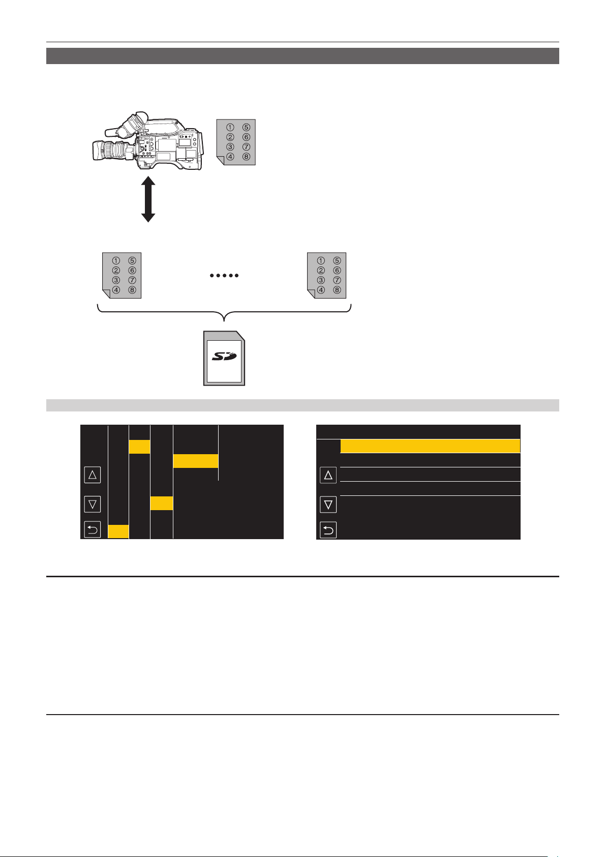
– 176 –
Chapter 5 Shooting — Scene le
Writing and loading lens les to and from SD card
Eight lens les stored in the internal memory on the camera can be written to a SD card as a single card le. For lens les written to the SD card, the
written single card le (eight lens les) can be loaded into the internal memory.
The following shows the relationship between lens les stored to the internal memory and card les written to the SD card.
Internal memory
Card file 1 Card file n
eight lens files
Up to eight lens files can be stored in internal memory.
The contents of the eight lens files can be written to and loaded from a SD card as a single card file.
Writing lens les to SD card
1/4
2
4
1
LENS004
LENS003
LENS002
LENS001
3
08:11:06
08:10:00
08:08:11
08:05:10
MENU>OTHERS>FILE>LENS FILE(SD CARD)>SAVE
DEC-01-2019
DEC-01-2019
DEC-01-2019
DEC-01-2019
Fig. 1 Fig. 2
CAMERA
SCENE FILE
AUDIO
VIDEO OUT/LCD/VF
RECORDING
NETWORK
SYSTEM
OTHERS
EXIT
FILE
BATTERY
GENLOCK
COLOR BARS
LED
CLOCK
GPS
SETUP FILE(SD CARD)
SETUP FILE(MEMORY)
LENS FILE(MEMORY)
SLOT FOR LOAD/SAVE
SCENE FILE(SD CARD)
EXIT
CAC FILE(SD CARD)
LOAD
SAVE
SAVE AS
EXIT
LENS FILE(SD CARD)
Saving a lens le as a new le on a SD card
Current setting values of the camera is saved as a new le in a SD card by specifying the card le name.
1
Select the [OTHERS] menu → [FILE] → [LENS FILE(SD CARD)] → [SAVE AS].
The card le name entry screen and the keyboard are displayed.
2
Enter the text to set with the keyboard.
3
Select [Enter].
A conrmation screen is displayed.
4
Select [SET].
The card le is saved.
Overwriting a lens le on a SD card
Overwrites the le selected in the list of the card les saved on the SD card with the current setting values of the camera.
1
Select the [OTHERS] menu → [FILE] → [LENS FILE(SD CARD)] → [SAVE]. (Fig. 1)
The list of card les saved on the SD card is displayed.
2
Select the file to overwrite from the list of card files. (Fig. 2)
The card le name entry screen and the keyboard are displayed. Leave it as is when overwriting.

– 177 –
Chapter 5 Shooting — Scene le
3
Select [Enter].
A conrmation screen is displayed.
4
Select [SET].
The card le is saved.
f An error message may be displayed. For error message, refer to “Warning system” (page 227).
Loading lens les from SD card
1
Select the [OTHERS] menu → [FILE] → [LENS FILE(SD CARD)] → [LOAD].
The list of card les saved on the SD card is displayed.
2
Select the card file to load.
A conrmation screen is displayed.
3
Select [SET].
Loading of the le begins.
4
When the completion message is displayed, press the jog dial button (or <SET> button).
f An error message may be displayed. For error message, refer to “Warning system” (page 227).
@
NOTE
t Titles of lens les included in the card le saved in the SD card are not displayed in the [LENS FILE(SD CARD)] screen. Load the le each time and
conrm them in the [LENS FILE(MEMORY)] screen. Lens le in the internal memory will be overwritten when loading the lens le. Backup the lens le
in the internal memory by writing it on the SD card before loading a lens le from a SD card.
CAC le
For details, refer to “Chromatic aberration compensation function (CAC)” (page 39).

Data including additional information such as image, audio, and meta data that are recorded by single shooting is saved as a clip. Playback, copy, etc.,
of the clip can be performed on the camera.
Chapter 6 Playback
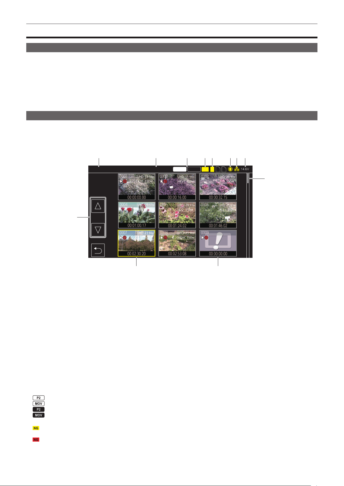
– 179 –
Chapter 6 Playback — Thumbnail operation
Thumbnail operation
Thumbnail operation overview
A clip is a group of data recorded by a single shooting, which includes additional information such as image, audio, and meta data.
The following operations can be performed while viewing the clip thumbnails displayed on the LCD monitor.
There are two methods of operation, a method to operate with the jog dial button or the cursor operation button, and a method to touch the LCD monitor.
f Playback
f Delete
f Protect (only the clips recorded in MOV format)
f Copy (only the clips recorded in P2 format)
f Re-connect (only the clips recorded in P2 format)
Thumbnail screen
Press the <THUMBNAIL> button to display the thumbnail screen while displaying the camera image screen.
Press the <THUMBNAIL> button again to display the camera image screen.
The clip in the recording le format (P2 or MOV) selected in the [SYSTEM] menu → [FILE FORMAT] is displayed in the thumbnail screen.
Also, menu in the thumbnail screen can be operated by pressing the <MENU> button while the thumbnail screen is displayed.
P2 MOV
14.6V
NG
2 3
1
1
9
2 3 54 76 8
12
11 10
ALL SLOT PROTECT
1 Clip status display
[ALL SLOT]: Displays all the clips recorded on every memory card in each card slot.
Displays in [ALL SLOT] when switched from the camera image screen to the thumbnail screen.
[SLOT1]: Displays only the clips recorded on the memory card in card slot 1.
[SLOT2]: Displays only the clips recorded on the memory card in card slot 2.
[SLOT3]: Displays only the clips recorded on the memory card in card slot 3.
[SAME FORMAT]: Displays only the clips recorded in the same format as the system format.
Clips recorded in the same format means that each item of the [SYSTEM] menu → [FREQUENCY]/[FILE FORMAT]/[REC FORMAT]/[AUDIO
SAMPLE RES.] matches the current setting status.
[MARKED]: Only the clips with shot mark are displayed.
Following items are also displayed when set to the [SYSTEM] menu → [FILE FORMAT] → [P2].
[SLOT1→SLOT2]: Displayed when copying from the memory card in card slot 1 to the memory card in card slot 2.
[SLOT1→SLOT3]: Displayed when copying from the memory card in card slot 1 to the memory card in card slot 3.
[SLOT2→SLOT1]: Displayed when copying from the memory card in card slot 2 to the memory card in card slot 1.
[SLOT2→SLOT3]: Displayed when copying from the memory card in card slot 2 to the memory card in card slot 3.
[SLOT3→SLOT1]: Displayed when copying from the memory card in card slot 3 to the memory card in card slot 1.
[SLOT3→SLOT2]: Displayed when copying from the memory card in card slot 3 to the memory card in card slot 2.
2 Function display
This is displayed during the operation of copy, delete, protect, etc.
3 Recording mode
: Displayed when P2 is selected as the recording le format.
: Displayed when MOV is selected as the recording le format.
: Displayed when MOV is selected as the recording le format, and there is at least one P2 clip on any of the memory cards.
: Displayed when P2 is selected as the recording le format, and there is at least one MOV clip on any of the memory cards.
4 Defective clip status
: Displayed when P2 is selected as the recording le format and there is at least one defective P2 clip that may be repaired in the thumbnail
screen.
: Displayed when P2 is selected as the recording le format and there is at least one defective P2 clip that cannot be repaired in the thumbnail
screen.
(No display): There is no defective P2 clip in the thumbnail screen.
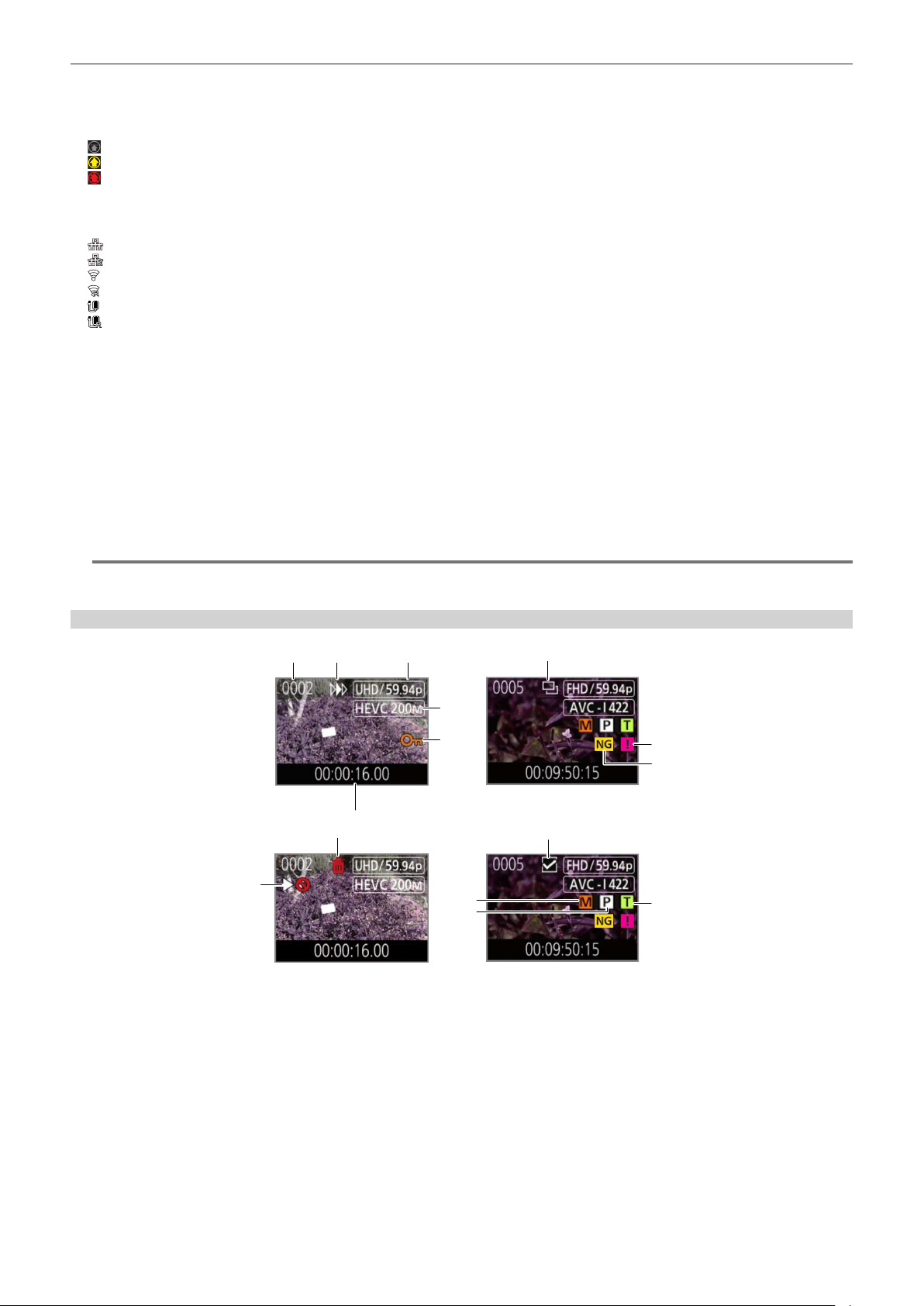
– 180 –
Chapter 6 Playback — Thumbnail operation
5 Media status display
The card slot number of the memory card where the clip in the cursor position is recorded is displayed in yellow.
6 Upload status display
Displays the status of the contents upload.
: Displayed in gray when the upload has not started or when the upload has completed.
: Displayed in yellow when the upload is in progress.
: Displayed when an upload error has occurred.
7 Connection status of the wired LAN, wireless LAN, and USB tethering
Displays the connection status of the wired LAN, wireless LAN, and USB tethering.
(No display): It is not connected via wired LAN or wireless LAN. It is set to the [NETWORK] menu → [DEVICE SEL] → [OFF].
: It is set to the wired LAN, and ROP is not connected.
: It is set to the wired LAN, and ROP is connected.
: It is set to the wireless LAN, and ROP is not connected.
: It is set to the wireless LAN, and ROP is connected.
: It is set to the USB tethering, and ROP is not connected.
: It is set to the USB tethering, and ROP is connected.
8 Battery status display
Displays the battery remaining capacity.
Display unit is “V” (voltage display) or “%” (percentage display).
9 Scroll bar
Indicates which part of the whole thumbnail is currently being viewed.
10 Clip that cannot be played back
Displays when the clip cannot be played back in the camera such as standard violation.
11 Cursor
12 Page switching button
Switches the page of the thumbnail screen.
[`]: Moves to previous page
[{]: Moves to next page
@
NOTE
t When P2 is selected as the recording le format, a clip recorded over multiple memory cards is displayed as one clip.
t MOV clip and P2 clip cannot be displayed in the thumbnail screen simultaneously.
Display of the clips in the thumbnail screen
2
7
1
8
9
3
4
6
5
11
12
10
15
14
13
1 Thumbnail number
Displays the thumbnail number in [0001] to [9999].
Normally, the number assigned to the clip in the order of recording is displayed.
2 Resume play status
3 Number of recording pixels, system frequency
4 Recording le format, recording codec
5 Protection status of the clip
This is displayed when the clip is protected.
6 Standard time code/clip name
The rst eight digits for the time code when starting shooting of a clip or the le name of the clip are displayed in alphanumeric.
The information to display is set in the [THUMBNAIL] menu → [DISPLAY] → [DATA].
7 Delete selection status
8 Clip that cannot be played back
This is displayed when the clip cannot be played back with the camera because the system frequency is different, etc.
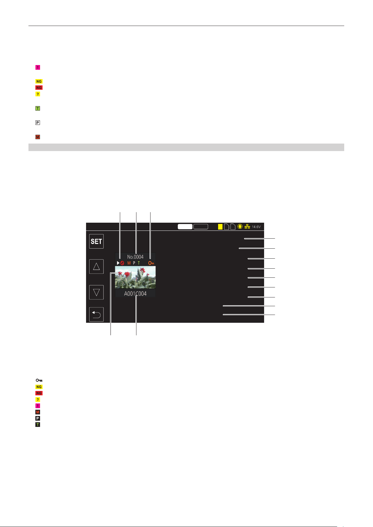
– 181 –
Chapter 6 Playback — Thumbnail operation
9 Copy selection status
This is displayed when the clip is selected.
10 Re-connection selection status
This is displayed when the clip to be re-connected is selected.
11 Incomplete clip
: This is displayed for a P2 clip when the clip is recorded over multiple memory cards, and any of those memory cards are not inserted.
12 Defective clip/unknown clip
: This is displayed for a defective P2 clip that may be repaired.
: This is displayed for a defective P2 clip that cannot be repaired.
: This is displayed for a P2 clip with a different format for P2 standard.
13 Clip with text memo
: This is displayed on the clip with a text memo data.
14 Clip with proxy
: This is displayed on the clip with a proxy recorded.
15 Clip with shot mark
: This is displayed on the clip with a shot mark attached. For details, refer to “Shot mark recording function” (page 146).
Display of clip information
Displays the information of the clip where the cursor is positioned.
1
Move the yellow cursor to the clip to display the clip information.
2
Select the [THUMBNAIL] menu → [CLIP] → [INFORMATION].
The clip information is displayed.
r Clip information
00:01:00.17
00000000
2019 OCT 27
12:43:07(GMT+09:00)
00:00:23.15
3840x2160/29.97p
MOV HEVC LonG 150M
60fps
HD
2 3
14.6V
P2 MOV
1
1 2 3
6
4 5
7
8
9
10
11
12
13
14
START TC
START UB
DATE
TIME
DURATION
PIXEL/FREQ
CODEC
FRAME RATE
GAMMA
CLIP INFO.
1 Clip that cannot be played back
This is displayed when the clip cannot be played back with the camera because the system frequency is different, etc.
2 Thumbnail number
3 Protection status of the clip/defective clip/unknown clip/incomplete clip/shot mark/proxy/text memo
: This is displayed when the clip is protected.
: This is displayed for a defective P2 clip that may be repaired.
: This is displayed for a defective P2 clip that cannot be repaired.
: This is displayed for a P2 clip with a different format for P2 standard.
: This is displayed for a P2 clip when the clip is recorded over multiple memory cards, and any of those memory cards are not inserted.
: This is displayed on the clip with a shot mark attached. For details, refer to “Shot mark recording function” (page 146).
: This is displayed on the clip with a proxy recorded.
: This is displayed on the clip with a text memo data.
4 Thumbnail image
5 Clip name
6 [START TC]
Displays the time code value at the start of the recording.
7 [START UB]
Displays the user bits value at the start of the recording.
8 [DATE]
Displays the date of the recording.
9 [TIME]
Displays the time at the start of recording.

– 182 –
Chapter 6 Playback — Thumbnail operation
10 [DURATION]
Displays the time length of the clip.
11 [PIXEL/FREQ]
Displays the recording format of the clip.
12 [CODEC]/[CODEC/AUDIO]
Displays the recording le format and the recording codec of the clip.
Displays the number of bits of the audio of the clip when recording format is AVC-Intra 100/AVC-Intra 50.
13 [FRAME RATE]
Displays the recording frame rate of the clip.
This camera does not support variable frame rate recording function and this item is not displayed in clips recorded by this camera.
14 [GAMMA]
Displays the gamma of the clip.
Displays [V-Log] when the [SYSTEM] menu → [COLOR SETTING] → [V-Log] is set and recording is performed
Displaying the clip metadata
Displays the metadata recorded in the clip where the cursor is positioned.
Tokyo Tower
060A2B340101010501010D4313000000205A266B209205F400804582F
00002DD
:
:
CLIP INFO.
VIDEO
GLOBAL CLIP ID/USER CLIP NAME
AUDIO
ACCESS
DEVICE
SHOOT
SCENARIO
NEWS
CLIP INFO.>GLOBAL CLIP ID/USER CLIP NAME
GLOBAL CLIP ID
USER CLIP NAME
Fig. 1 Fig. 2
1
Move the yellow cursor to the clip to display the clip information.
2
Select the [THUMBNAIL] menu → [CLIP] → [INFORMATION].
The clip information is displayed.
3
Select [SET].
The clip meta item screen is displayed. (Fig. 1)
The clip meta details screen is displayed by selecting the clip meta item to display. (Fig. 2)
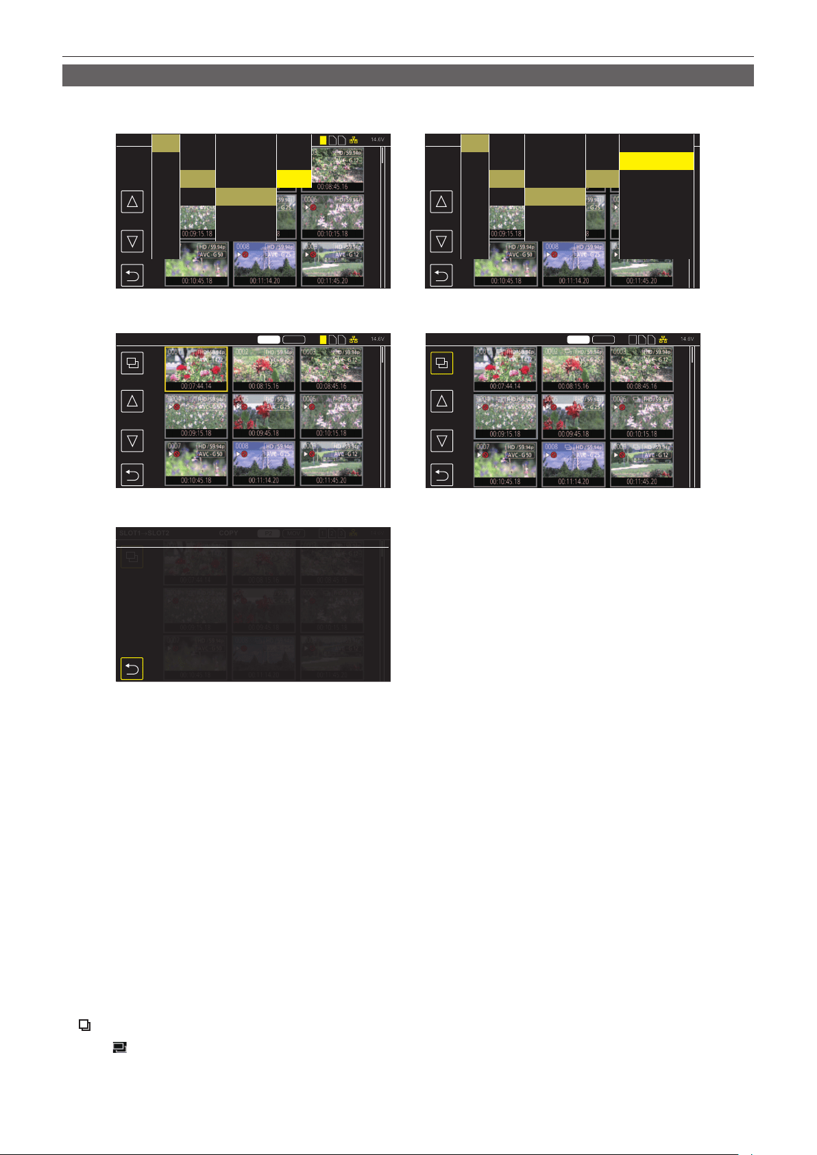
– 183 –
Chapter 6 Playback — Thumbnail operation
Copying clips
Clips can be copied between memory cards.
Only the clip recorded in P2 can be copied.
MOV
1 2 3
14.6V
MOV
1 2
14.6V
P2 MOV
14.6V
14.6V
14.6V
1 2 3 1 2 3
1 2 3
P2 MOV
P2 MOV
ALL SLOTALL SLOT
AUDIO
VIDEO OUT/LCD/VF
RECORDING
NETWORK
SYSTEM
OTHERS
THUMBNAIL
SLOT1
→
SLOT2
COPY
COPY
SLOT1
→
SLOT2
COPY
SLOT1
→
SLOT2
COPY
COPY
COPY completed.
CLIP
DISPLAY
PLAYBACK
EXIT
COPY
REPAIR
INFORMATION
DELETE
PROTECT
EXIT
ALL
SELECT
EXIT
AUDIO
VIDEO OUT/LCD/VF
RECORDING
NETWORK
SYSTEM
OTHERS
THUMBNAIL
COPY
CLIP
DISPLAY
PLAYBACK
EXIT
COPY
REPAIR
INFORMATION
DELETE
PROTECT
EXIT
ALL
SELECT
EXIT
SLOT1
→
SLOT2
SLOT1
→
SLOT3
SLOT2
→
SLOT1
SLOT2
→
SLOT3
SLOT3
→
SLOT1
SLOT3
→
SLOT2
EXIT
Fig. 1 Fig. 2
Fig. 4Fig. 3
Fig. 5
1
Press the <THUMBNAIL> button.
The thumbnail screen is displayed.
2
Press the <MENU> button while the thumbnail screen is displayed.
The menu is displayed.
3
Select the [THUMBNAIL] menu → [CLIP] → [COPY].
4
Select [SELECT]. (Fig. 1)
f All clips can be copied between the memory cards when [ALL] is selected.
5
Select the card slot for the copy destination. (Fig. 2)
The clips on the memory card of the copy source is displayed in the thumbnail screen. (Fig. 3)
f [SLOT1→SLOT2]: Copies clips from the memory card in card slot 1 to the memory card in card slot 2.
f [SLOT1→SLOT3]: Copies clips from the memory card in card slot 1 to the memory card in card slot 3.
f [SLOT2→SLOT1]: Copies clips from the memory card in card slot 2 to the memory card in card slot 1.
f [SLOT2→SLOT3]: Copies clips from the memory card in card slot 2 to the memory card in card slot 3.
f [SLOT3→SLOT1]: Copies clips from the memory card in card slot 3 to the memory card in card slot 1.
f [SLOT3→SLOT2]: Copies clips from the memory card in card slot 3 to the memory card in card slot 2.
6
Select the clip to copy in the thumbnail screen.
is displayed on the selected clip.
7
Select
. (Fig. 4)
f This can also be selected by pressing and holding the jog dial button.
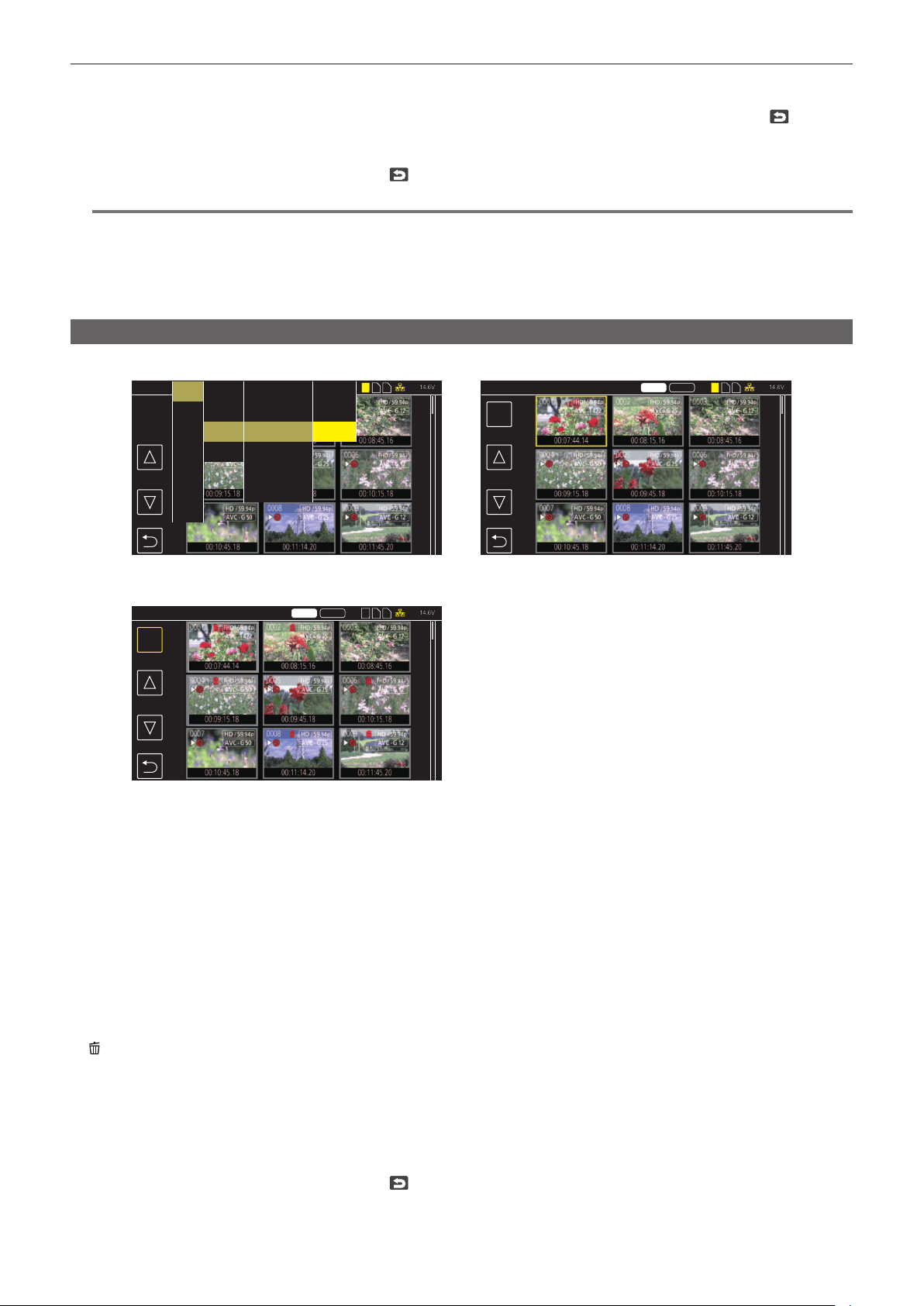
– 184 –
Chapter 6 Playback — Thumbnail operation
8
When the confirmation message is displayed, select [SET].
Progress bar is displayed, and the copy of the clip starts.
[OVERWRITE?] is displayed when there is a same P2 clip in the copy destination. Select [SET] when overwriting the clip, and select
when not
overwriting the clip.
f To cancel the copy midway, select [CANCEL].
9
When the completion message is displayed, select
. (Fig. 5)
@
NOTE
t Clips in MOV format cannot be copied.
t The copy is not possible when the volume of the selected clip is larger than the available memory card capacity of the destination.
t The copy is not possible when the copy destination memory card is write protected.
t The copy is not possible when it will exceed the maximum number of clips.
t The P2 clip exceeding 4 GB cannot be copied to a memory card of 32 GB or less.
t The P2 clip recorded over multiple memory cards cannot be copied to a same memory card.
Deleting clips
Deletes the clip.
DEL
DEL
MOV
14.6V
14.6V
14.6V
1 2 3 1 2 3
1 2 3
P2 MOV
P2 MOV
ALL SLOT
OTHERS
ALL SLOT DELETE
ALL SLOT DELETE
Fig. 1 Fig. 2
Fig. 3
AUDIO
VIDEO OUT/LCD/VF
RECORDING
NETWORK
SYSTEM
OTHERS
THUMBNAIL
COPY
CLIP
DISPLAY
PLAYBACK
EXIT
COPY
REPAIR
INFORMATION
DELETE
PROTECT
EXIT
ALL
SELECT
EXIT
1
Press the <THUMBNAIL> button.
The thumbnail screen is displayed.
2
Press the <MENU> button while the thumbnail screen is displayed.
The menu is displayed.
3
Select the [THUMBNAIL] menu → [CLIP] → [DELETE].
4
Select [SELECT]. (Fig. 1)
The thumbnail screen is displayed. (Fig. 2)
f When [ALL] is selected, all the clips displayed in the thumbnail screen are deleted.
The clip that is not displayed in the thumbnail screen is not deleted.
5
Select the clip to delete in the thumbnail screen.
is displayed on the selected clip.
6
Select [DEL]. (Fig. 3)
f This can also be selected by pressing and holding the jog dial button.
7
When the confirmation message is displayed, select [SET].
Progress bar is displayed, and the deleting of the clip starts.
f To cancel midway, select [CANCEL].
8
When the completion message is displayed, select
.

– 185 –
Chapter 6 Playback — Thumbnail operation
@
NOTE
t The protected clip cannot be deleted.
t Deleting is not possible when the memory card with the clip to delete is write protected.
t The clip can be deleted even if the contents upload function is operating, but the upload may not have completed.
Protecting clips
The clip recorded in MOV format can be protected.
1
Press the <THUMBNAIL> button.
The thumbnail screen is displayed.
2
Press the <MENU> button while the thumbnail screen is displayed.
The menu is displayed.
3
Select the [THUMBNAIL] menu → [CLIP] → [PROTECT].
4
Select [SELECT].
The thumbnail screen is displayed.
5
Select the clip to protect in the thumbnail screen.
is displayed on the selected clip.
f Protect is canceled when the protected clip is selected.
@
NOTE
t Protecting is not possible when the memory card with the clip to protect is write protected.
t Clips in P2 format cannot be protected.
Adding shot mark to a clip
This camera can add a shot mark to the thumbnail of a clip to distinguish from other clips.
r Assigning [SHOT MARK] to the USER button
1
Select the [CAMERA] menu → [USER SW] → [USER1] to [USER5] → [SHOT MARK].
r Adding shot mark to the thumbnail of a clip
1
Press the <THUMBNAIL> button.
The thumbnail screen is displayed.
2
Move the yellow cursor to the clip to add a shot mark.
3
Press the USER button assigned with [SHOT MARK].
A shot mark is added to the thumbnail of the clip where the cursor is.
f To delete a shot mark, move the cursor to it again and press the USER button assigned with [SHOT MARK].
@
NOTE
t Shot mark can be added/cleared only on the clips in P2 format.
t The shot mark can also be added while recording.
By adding a shot mark after stopping the recording, a shot mark can be added to the clip recorded immediately before that.
For details, refer to “Shot mark recording function” (page 146).
t When adding/clearing a shot mark on a clip spanning across multiple memory cards, it is necessary to insert all the memory cards with that clip
recorded into the card slots.
Restoring clips
In following cases, restoration of the clip may be required depending on the condition. It may take some time to restore depending on the error.
f When the memory card in the card slot with the card access lamp is ashing is removed
f When the power is turned off by removing the battery or the external DC power supply while recording or performing record completion process
Restoring a clip (P2 format)
An error message is not displayed when P2 is selected as the recording le format.
is displayed in the thumbnail screen when there is at least one defective P2 clip that may be repaired in the thumbnail screen. In such case, the clip
can be repaired in following procedure.
1
Press the <THUMBNAIL> button.
The thumbnail screen is displayed.
2
Press the <MENU> button while the thumbnail screen is displayed.
The menu is displayed.
3
Select the [THUMBNAIL] menu → [CLIP] → [REPAIR].
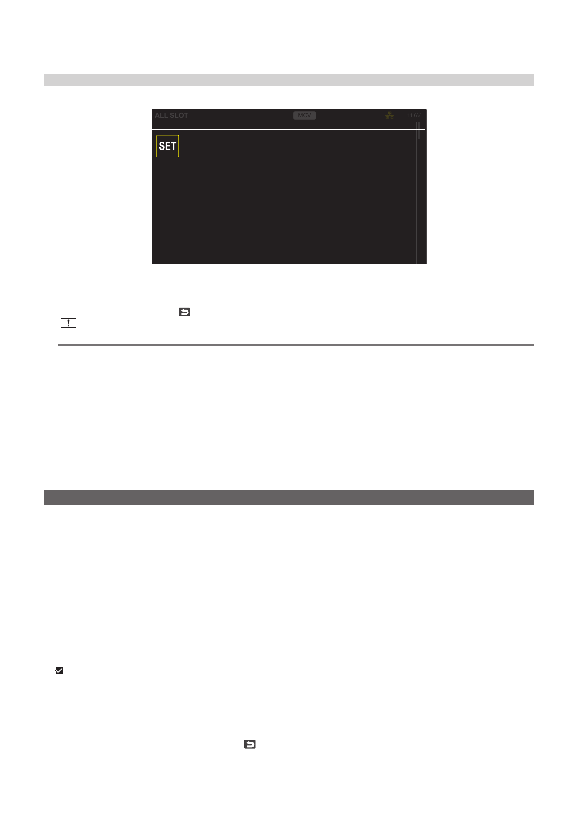
– 186 –
Chapter 6 Playback — Thumbnail operation
4
Select [YES].
All the defective P2 clips that may be repaired in the thumbnail screen are repaired.
Restoring a clip (MOV format)
An error as in following gure is displayed when MOV is selected as the recording le format.
COPY
MOV
14.6V
ALL SLOT
Repair
There are clips that need restoration.
Fig. 1
1
Select [SET] in the error message screen. (Fig. 1)
f Once the repair is completed, select
in the conrmation message. It will return to the previous screen.
f
is displayed on the clip when an abnormal management information is detected while displaying the thumbnail.
@
NOTE
t Do not remove the memory card in the card slot that is ashing, or do not remove the battery or the external DC power supply when the card access
lamp is ashing in orange. Doing so will cause damage to the memory card.
t Use a sufciently charged battery or external DC power supply.
t It may not be possible to completely repair depending on the condition of the data.
t To restore the clips, it is necessary that the clips are recorded for more than a certain amount of time. Especially in the following cases, the clips may
not be restored, because the number of frames to be recorded is small.
- When the interval recording is enabled.
t The clips shot before the power was turned off will not be able playback if the repair fails.
Also, it may not be possible to record any more.
t If data recorded with other device is repaired, it may not be able to play back on the camera or other device.
t If the repair failed, turn off the camera, and turn it back on after waiting for a while. If the repair fails repeatedly, format with the camera. All data will be
erased when it is formatted, and it cannot be restored.
t Display of the thumbnail become slower when the thumbnail information is repaired.
t The proxy data is deleted when a defective clip including a proxy data in P2 format is restored.
Linking the incomplete clips
The linked P2 clips recorded over multiple memory cards may become incomplete clips due to being copied separately from each memory card.
These can be restored to original linked clips by using the link function.
Only the P2 clips can be linked.
1
Press the <THUMBNAIL> button.
The thumbnail screen is displayed.
2
Press the <MENU> button while the thumbnail screen is displayed.
The menu is displayed.
3
Select the [THUMBNAIL] menu → [CLIP] → [RE-CONNECT].
4
Select [SELECT].
The thumbnail screen is displayed.
5
Select the clip to link in the thumbnail screen.
is displayed next to the thumbnail number on the selected clip.
6
Select [SET].
f This can also be selected by pressing and holding the jog dial button.
7
Select [SET] when the confirmation message is displayed.
This starts linking of the clip.
8
When the completion message is displayed, select .
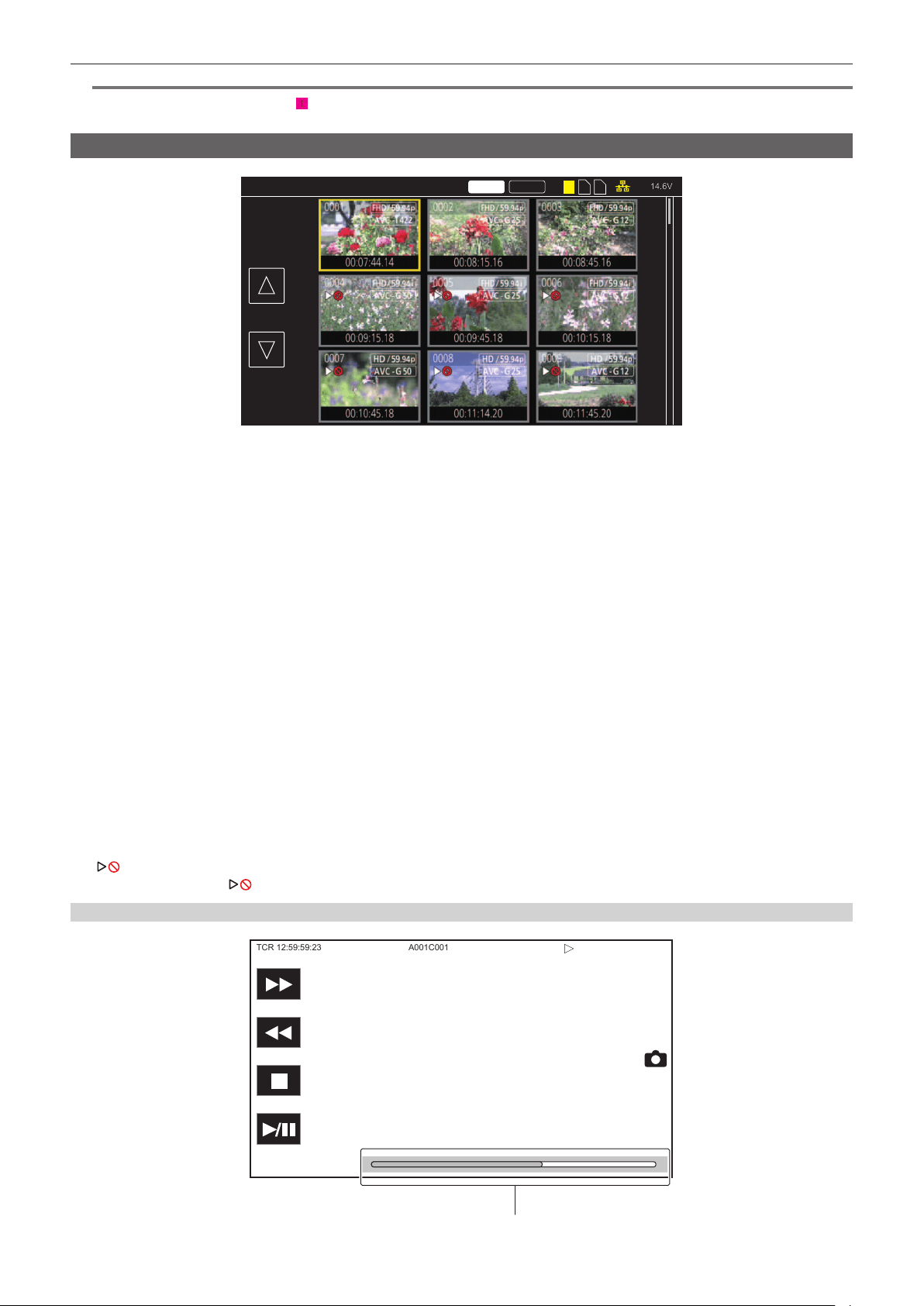
– 187 –
Chapter 6 Playback — Thumbnail operation
@
NOTE
t Even though some clips are reconnected,
will remain displayed when all the clips constituting the original linked clip are not present.
t Linking is not possible when the memory card with the clips to link is write-protected.
Playing back clips
14.6V
2 31
P2 MOV
ALL SLOT
Fig. 1
1
In the [SYSTEM] menu → [FREQUENCY], select the system frequency to play back.
2
In the [SYSTEM] menu → [FILE FORMAT], select the file format to play back.
3
In the [SYSTEM] menu → [REC FORMAT], select the signal format and codec mode to play back.
4
Press the <THUMBNAIL> button.
The thumbnail screen is displayed.
5
Press the <MENU> button while the thumbnail screen is displayed.
The menu is displayed.
6
In the [THUMBNAIL] menu → [PLAYBACK] → [CLIP SEL], select the card slot of the memory card to play back.
[ALL SLOT]: Displays all the clips recorded on every memory card in each card slot.
Displays in the order of the clips in the card slot 1, clips in the card slot 2, and then clips in the card slot 3 when MOV is selected as the recording le
format.
Displays the clips on all the memory cards in the order of the recording date and time when P2 is selected as the recording le format.
[SLOT1]: Displays only the clips recorded on the memory card in card slot 1.
[SLOT2]: Displays only the clips recorded on the memory card in card slot 2.
[SLOT3]: Displays only the clips recorded on the memory card in card slot 3.
[SAME FORMAT]: Displays only the clips recorded in the same format as the system format.
Clips recorded in the same format means that each item of the [SYSTEM] menu → [FREQUENCY]/[FILE FORMAT]/[REC FORMAT]/[AUDIO
SAMPLE RES.] matches the current setting status.
7
Select the clip to play back. (Fig. 1)
f
is displayed on the clip that cannot be played back.
f To play back the clip with
displayed, check the information of the clip with the clip information, and try operating from the beginning again.
Playback from button operations and operation icons
TCR 12:59:59:23
A001C001
Direct playback bar

– 188 –
Chapter 6 Playback — Thumbnail operation
Playback operation Operating procedure
Playback/pause
Touch [=/&] or press the <PLAY/PAUSE (=/&)> button.
Fast-reverse playback
Touch [%] or press the <REV (%)> button. Touch twice to increase the speed.
Fast-forward playback
Touch [)] or press the <FWD ())> button. Touch twice to increase the speed.
Stop (return to thumbnail screen)
Touch [(] or press the <STOP (()> button.
Skip playback
(cue up of the clip)
Touch the LCD monitor while playing back, and slide from right to left (left to right).
When sliding from left to right, the clip skips to the beginning of the previous clip if the current playback
position of the clip is at less than three seconds from the beginning. The clip skips to the beginning of the
current clip if the current playback position of the clip is at three seconds or more from the beginning.
Skip playback is also possible by pressing the <FWD ())> button or <REV (%)> button while paused.
Slow playback
Touch and hold [&=] during pause.
Touch and hold [~&] for reverse slow playback.
It will perform slow playback with continuous frame-by-frame while [&=] is touched.
f Touch [=/&] or press the <PLAY/PAUSE (=/&)> button to return to normal playback.
f The frame-by-frame interval and the display time for each frame for the reverse slow playback differ
depending on the type of the clip.
Frame-by-frame playback
Touch [&=] during pause.
([~&] is for reverse frame-by-frame playback)
f Touch [=/&] or press the <PLAY/PAUSE (=/&)> button to return to normal playback.
f The frame-by-frame interval for reverse frame-by-frame playback differs depending on the type of the
clip.
Direct playback Touch the direct playback bar, or slide it while touching.
f The playback video is paused during the operation. Playback is started by releasing the nger.
@
NOTE
t Operations of the camera or some performance may become slow for the clip with large le size.
t Operations of the camera or some performance may become slow when there are large number of clips on the memory card.
t Playback will stop once by switching the card slot when MOV is selected as the recording le format, and the [THUMBNAIL] menu → [PLAYBACK] →
[CLIP SEL] → [ALL SLOT]/[SAME FORMAT] is set, and the clips of all the memory cards are displayed. Playback is not possible across two memory
cards.
t If selecting P2 as recording le format and playing back a clip that was recorded by relay recording and spans between two memory card, playback
will pause and a black screen will be displayed when switching the card slot. Playback will automatically restart after the switch.
t Playback stops when the memory card is removed during playback.
t During playback of a clip, playback may be suspended or black screen may be displayed due to switching of a clip.

– 189 –
Chapter 6 Playback — Useful playback function
Useful playback function
Resume play
When the playback of a clip is stopped midway, it will start the playback from the position that stopped the playback when it is played back the next time.
1
Select the [THUMBNAIL] menu → [PLAYBACK] → [RESUME PLAY] → [ON].
When the playback of a clip is stopped midway, [L] is displayed on the clip in the thumbnail screen.
@
NOTE
t Resume playback is canceled in following cases.
- When the power is turned off
- When the thumbnail screen is canceled by pressing the <THUMBNAIL> button
- When the [SYSTEM] menu → [REC FORMAT] is changed

– 190 –
Chapter 6 Playback — Still image recording function
Still image recording function
One frame of the recorded video can be recorded as a still image.
Number of pixels of the still image to be recorded is same as the number of pixels of the recorded video.
1
Select by touching
or pressing the jog dial button at the scene to be recorded as a still image while playing back.
The still image is recorded in the memory card being played back.
@
NOTE
t The playback will pause when a still image is recorded.
t Recorded still image cannot be displayed in thumbnail, played back, copied, or deleted in the camera.
t [INVALID] is displayed when the still image cannot be recorded in cases such as there is not enough remaining capacity in the memory card.

This chapter describes about the output image.
Chapter 7 Output
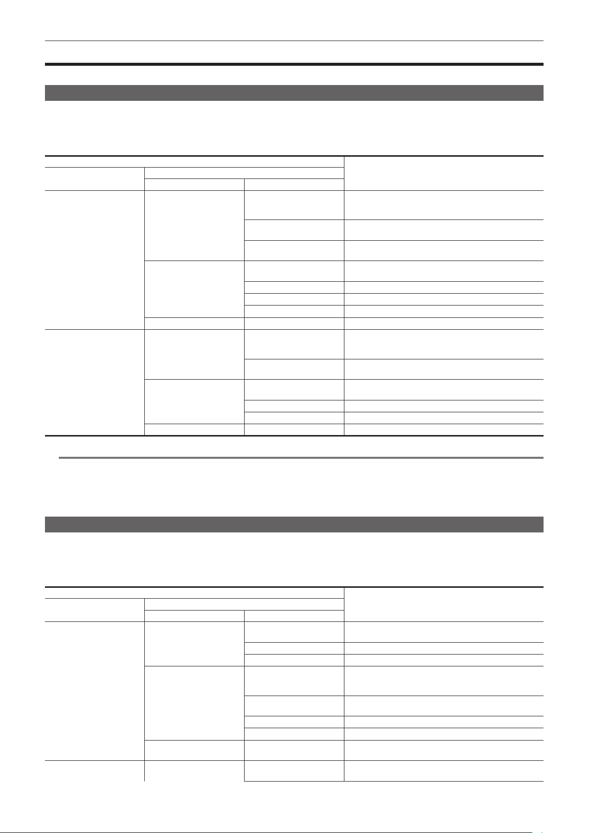
– 192 –
Chapter 7 Output — Output format
Output format
The format to be output differs depending on the setting in the [SYSTEM] menu → [FREQUENCY]/[REC FORMAT].
Format that can be output from the <SDI OUT1> terminal
The format that can be output from the <SDI OUT1> terminal differs with following combinations of the settings.
f [SYSTEM] menu → [FREQUENCY]
f [SYSTEM] menu → [REC FORMAT]
f [VIDEO OUT/LCD/VF] menu → [SDI OUT1] → [OUT FORMAT]
Item
Output Format
[OUT FORMAT]
[FREQUENCY]
[REC FORMAT]
Resolution Frequency
[59.94Hz]
3840×2160
59.94p
3840×2160 59.94p
1920×1080 59.94p
1920×1080 59.94i (Factory setting)
29.97p
3840×2160 29.97p
1920×1080 29.97PsF (Factory setting)
23.98p
3840×2160 23.98p
1920×1080 23.98PsF (Factory setting)
1920×1080
59.94p
1920×1080 59.94p
1920×1080 59.94i (Factory setting)
59.94i
1920×1080 59.94i
29.97p
1920×1080 29.97PsF
23.98p
1920×1080 23.98PsF
1280×720
59.94p
1280×720 59.94p
[50.00Hz]
3840×2160
50.00p
3840×2160 50.00p
1920×1080 50.00p
1920×1080 50.00i (Factory setting)
25.00p
3840×2160 25.00p
1920×1080 25.00PsF (Factory setting)
1920×1080
50.00p
1920×1080 50.00p
1920×1080 50.00i (Factory setting)
50.00i
1920×1080 50.00i
25.00p
1920×1080 25.00PsF
1280×720
50.00p
1280×720 50.00p
@
NOTE
t [OUT FORMAT] restores the factory settings when the settings of [FREQUENCY] and [REC FORMAT] change and the current setting values of [OUT
FORMAT] cannot be acquired.
t The output format when playing back from the thumbnail screen is as follows.
- It will be the value set in [OUT FORMAT] when the recording resolution of the playback clip is the same as [REC FORMAT].
- It will be factory setting of [OUT FORMAT] when the recording resolution of the playback clip is different from [REC FORMAT].
Format that can be output from the <SDI OUT2> terminal
The format that can be output from the <SDI OUT2> terminal differs with following combinations of the settings.
f [SYSTEM] menu → [FREQUENCY]
f [SYSTEM] menu → [REC FORMAT]
f [VIDEO OUT/LCD/VF] menu → [SDI OUT2] → [OUT FORMAT]
Item
Output format
[OUT FORMAT]
[FREQUENCY]
[REC FORMAT]
Resolution Frequency
[59.94Hz]
3840×2160
59.94p
1920×1080 59.94p
1920×1080 59.94i (Factory setting)
29.97p
1920×1080 29.97PsF
23.98p
1920×1080 23.98PsF
1920×1080
59.94p
1920×1080 59.94p
1920×1080 59.94i (Factory setting)
720×480 59.94i
59.94i
1920×1080 59.94i (Factory setting)
720×480 59.94i
29.97p
1920×1080 29.97PsF
23.98p
1920×1080 23.98PsF
1280×720
59.94p
1280×720 59.94p (Factory setting)
720×480 59.94i
[50.00Hz]
3840×2160
50.00p
1920×1080 50.00p
1920×1080 50.00i (Factory setting)
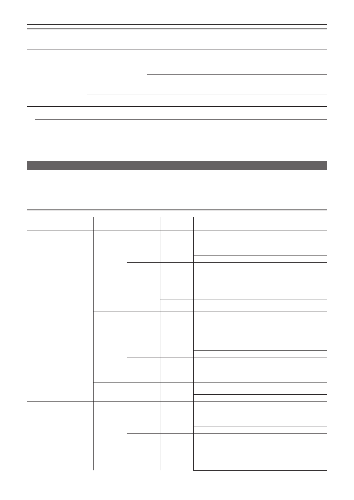
– 193 –
Chapter 7 Output — Output format
Item
Output format
[OUT FORMAT]
[FREQUENCY]
[REC FORMAT]
Resolution Frequency
25.00p
1920×1080 25.00PsF
1920×1080
50.00p
1920×1080 50.00p
1920×1080 50.00i (Factory setting)
720×576 50.00i
50.00i
1920×1080 50.00i (Factory setting)
720×576 50.00i
25.00p
1920×1080 25.00PsF
1280×720
50.00p
1280×720 50.00p (Factory setting)
720×576 50.00i
@
NOTE
t The <SDI OUT2> terminal does not support 3840×2160 output.
t [OUT FORMAT] restores the factory settings when the settings of [FREQUENCY] and [REC FORMAT] change and the current setting values of [OUT
FORMAT] cannot be acquired.
t The output format when playing back from the thumbnail screen is as follows.
- It will be the value set in [OUT FORMAT] when the recording resolution of the playback clip is the same as [REC FORMAT].
- It will be factory setting of [OUT FORMAT] when the recording resolution of the playback clip is different from [REC FORMAT].
Format that can be output from the <HDMI> terminal
The format that can be output from the <HDMI> terminal differs with following combination of the settings.
f [SYSTEM] menu → [FREQUENCY]
f [SYSTEM] menu → [REC FORMAT]
f [VIDEO OUT/LCD/VF] menu → [HDMI OUT] → [SIGNAL SEL]
f [VIDEO OUT/LCD/VF] menu → [SDI OUT2] → [OUT FORMAT]
Item
Output format
[FREQUENCY]
[REC FORMAT]
[SIGNAL SEL]
[SDI OUT2] → [OUT FORMAT]
Resolution Frequency
[59.94Hz]
3840×2160
59.94p [SDI
OUT1(2160p)]
1920×1080 59.94p
1920×1080 59.94i
3840×2160 59.94p
[SDI OUT2]
(Factory setting)
1920×1080 59.94p 1920×1080 59.94p
1920×1080 59.94i 1920×1080 59.94i
29.97p [SDI
OUT1(2160p)]
1920×1080 29.97PsF 3840×2160 29.97p
[SDI OUT2]
(Factory setting)
1920×1080 29.97PsF 1920×1080 29.97p
23.98p [SDI
OUT1(2160p)]
1920×1080 23.98PsF 3840×2160 23.98p
[SDI OUT2]
(Factory setting)
1920×1080 23.98PsF 1920×1080 23.98p
1920×1080
59.94p [SDI OUT2]
(Factory setting)
1920×1080 59.94p 1920×1080 59.94p
1920×1080 59.94i 1920×1080 59.94i
720×480 59.94i 720×480 59.94p
59.94i [SDI OUT2]
(Factory setting)
1920×1080 59.94i 1920×1080 59.94i
720×480 59.94i 720×480 59.94p
29.97p [SDI OUT2]
(Factory setting)
1920×1080 29.97PsF 1920×1080 29.97p
23.98p [SDI OUT2]
(Factory setting)
1920×1080 23.98PsF 1920×1080 23.98p
1280×720
59.94p [SDI OUT2]
(Factory setting)
1280×720 59.94p 1280×720 59.94p
720×480 59.94i 720×480 59.94p
[50.00Hz]
3840×2160
50.00p [SDI
OUT1(2160p)]
1920×1080 50.00p
1920×1080 50.00i
3840×2160 50.00p
[SDI OUT2]
(Factory setting)
1920×1080 50.00p 1920×1080 50.00p
1920×1080 50.00i 1920×1080 50.00i
25.00p [SDI
OUT1(2160p)]
1920×1080 25.00PsF 3840×2160 25.00p
[SDI OUT2]
(Factory setting)
1920×1080 25.00PsF 1920×1080 25.00p
1920×1080
50.00p [SDI OUT2]
(Factory setting)
1920×1080 50.00p 1920×1080 50.00p

– 194 –
Chapter 7 Output — Output format
Item
Output format
[FREQUENCY]
[REC FORMAT]
[SIGNAL SEL]
[SDI OUT2] → [OUT FORMAT]
Resolution Frequency
1920×1080 50.00i 1920×1080 50.00i
720×576 50.00i 720×576 50.00p
50.00i [SDI OUT2]
(Factory setting)
1920×1080 50.00i 1920×1080 50.00i
720×576 50.00i 720×576 50.00p
25.00p [SDI OUT2]
(Factory setting)
1920×1080 25.00PsF 1920×1080 25.00p
1280×720
50.00p [SDI OUT2]
(Factory setting)
1280×720 50.00p 1280×720 50.00p
720×576 50.00i 720×576 50.00p
@
NOTE
t The audio output from the <HDMI> terminal is two channels. The audio channel to output can be selected in the [AUDIO] menu → [OUTPUT
SETTINGS] → [HDMI OUT CH].
t The [VIDEO OUT/LCD/VF] menu → [HDMI OUT] → [SIGNAL SEL] → [SDI OUT1(2160p)]/[SDI OUT2] can be selected only when set to the [VIDEO
OUT/LCD/VF] menu → [SDI OUT1] → [OUT FORMAT] → [3840×2160p].
When the [VIDEO OUT/LCD/VF] menu → [SDI OUT1] → [OUT FORMAT] is set to anything other than [3840×2160p], the same signal output from the
<SDI OUT2> terminal is output from the <HDMI> terminal.

This chapter describes the external devices that can be connected to the camera.
Chapter 8 Connecting to External Devices
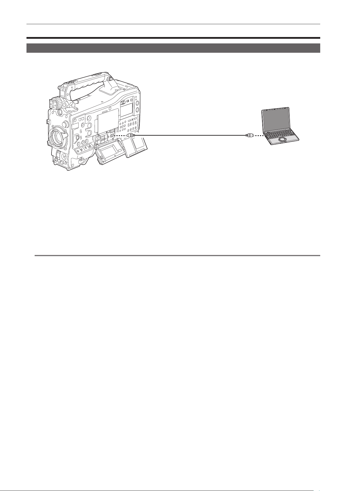
– 196 –
Chapter 8 Connecting to External Devices — Connection function via the <USB DEVICE> terminal
Connection function via the <USB DEVICE> terminal
Connecting to a computer in the card reader mode
Connect the camera to a computer via the USB type C cable to use the camera as a card reader for the memory card.
Connect with following procedure.
Computer
USB type C cable (optional)
Fig. 1
1
Connect the USB cable to the <USB DEVICE> terminal. (Fig. 1)
2
Select the [OTHERS] menu → [USB DEVICE] → [CARD READER MODE].
Connection is completed when [USB connected. Please operate via PC.] is displayed.
If the USB connection is being moved or it is not connected properly, [Connect this unit to PC using USB cable.] is displayed.
r Exiting the card reader mode
There are following methods.
f Turn the power switch of the camera to < h > (standby).
f Press the <EXIT> button.
After exiting the card reader mode, returns to camera shooting status in approximately ve seconds.
@
NOTE
t A USB type C cable is not supplied with this camera. Prepare a commercial USB type C cable (double-shielded for noise suppression).
t Using a USB cable 1.5 m or shorter is recommended.
t When connecting the camera to a computer via USB, ensure that no other device is connected to the computer via USB.
t Do not remove the memory card when connecting the camera via USB.
t The card access lamp while connected to USB will turn off unless accessing.
t When the camera is operating in the card reader mode, camera shooting, recording/playback operation, or thumbnail operation of the clip is not
allowed.
t When the camera is operating in the card reader mode, the remaining capacity and status of the memory card are not displayed. Also, video/audio
cannot be output or displayed.
t The LCD monitor lights up by touching the monitor if it has turned out to save energy.

– 197 –
Chapter 8 Connecting to External Devices — Connecting with a recording device or a monitor
Connecting with a recording device or a monitor
The camera directly controls the video and the monitor to output video.
Audio pin cable
HDMI cable
BNC cable (SDI)
Video equipment/monitor
@
NOTE
t VIERA Link is not supported on the camera. The VIERA Link of other device may not properly operate when connected to the VIERA Link compatible
device with a HDMI cable (optional).
t The SD resolution signal output from the <HDMI> terminal is output as a progressive signal (480P, 576P).
t Use a double-shielded cable equivalent to 5C-FB for the BNC cable (optional) that is connected to the <SDI OUT1> terminal or the <SDI OUT2>
terminal.
t Use the double-shielded cable supporting 4K/60p as the HDMI cable. Also, it is recommended to use the Panasonic HDMI cable supporting 4K/60p as
the HDMI cable.

– 198 –
Chapter 8 Connecting to External Devices — Connecting external devices and recording control function
Connecting external devices and recording control function
This camera supports remote function.
The recording operation of the external equipment can be controlled by superimposing the control signals to start the recording and pause the recording
into the image signal output from the <SDI OUT1>/<SDI OUT2>/<HDMI> terminal.
Remote function
The signal to control the external equipment is superimposed in the output signal coupled with the operation of the <REC> button on the camera.
The control signals to start the recording and pause the recording are alternately output every time the <REC> button is pressed.
f Recording is performed on both the memory card and the external equipment by inserting a memory card into the camera and pressing the <REC>
button.
f Recording is performed only in the external equipment when the <REC> button is pressed without inserting a memory card into the camera.
r Outputting from the <SDI OUT1>/<SDI OUT2> terminal
This is enabled by the [VIDEO OUT/LCD/VF] menu → [SDI OUT1]/[SDI OUT2] → [SDI REC REMOTE] → [ON].
r Outputting from the <HDMI OUT> terminal
This is enabled by the [VIDEO OUT/LCD/VF] menu → [HDMI OUT] → [HDMI REC REMOTE] → [ON].
@
NOTE
t The tally lamp is illuminated even when recording only on the external record.
t When the [OTHERS] menu → [LED] → [REC TALLY] → [GREEN]/[CHAR] is set, recording status of the camera is indicated with the green tally lamp
on the viewnder or with characters.
With this setting, it can be distinguished from the control status of the external device indicated by the tally lamp.
t The SDI and HDMI remote functions are disabled for the interval recording.
Conrming the control output status
The status of control is displayed in the viewnder or the monitor screen when the control signal is output.
The displayed status is not the recording status of the connected external equipment, but the status of the control signal output from the camera.
Displays the control status of the recording start and recording stop on the external equipment connected to the <SDI OUT1>/<SDI OUT2>/<HDMI>
terminals.
f [REC S/H]: Recording instruction is output to the output from the <SDI OUT1>/<SDI OUT2>/<HDMI> terminals.
f [S/H]: Pause instruction is output to the output from the <SDI OUT1>/<SDI OUT2>/<HDMI> terminals.
f [REC SDI]: Recording instruction is output to the output from the <SDI OUT1>/<SDI OUT2> terminals.
f [SDI]: Pause instruction is output to the output from the <SDI OUT1>/<SDI OUT2> terminals.
f [REC HDMI]: Recording instruction is output to the output from the <HDMI> terminal.
f [HDMI]: Pause instruction is output to the output from the <HDMI> terminal.

– 199 –
Chapter 8 Connecting to External Devices — Remote control by iPhone/iPad or Android terminal
Remote control by iPhone/iPad or Android terminal
The camera can be connected to the wireless LAN by attaching a wireless module (optional) compatible to the camera to the <USB2.0 HOST> terminal
of the camera.
Some of the functions can be remotely operated by connecting the camera with iPhone/iPad or Android terminal with the CX ROP app installed.
(page 211)

– 200 –
Chapter 8 Connecting to External Devices — Connecting the Remote Operation Panel (AK-HRP1000G/AK-HRP1005G)
Connecting the Remote Operation Panel (AK-HRP1000G/AK-HRP1005G)
Some of the functions can be remotely controlled by connecting the camera and the Remote Operation Panel AK-HRP1000G/AK-HRP1005G (optional)
with a LAN cable. (page 213)

This chapter describes how to use the camera by connecting to a network.
Chapter 9 Network Connection
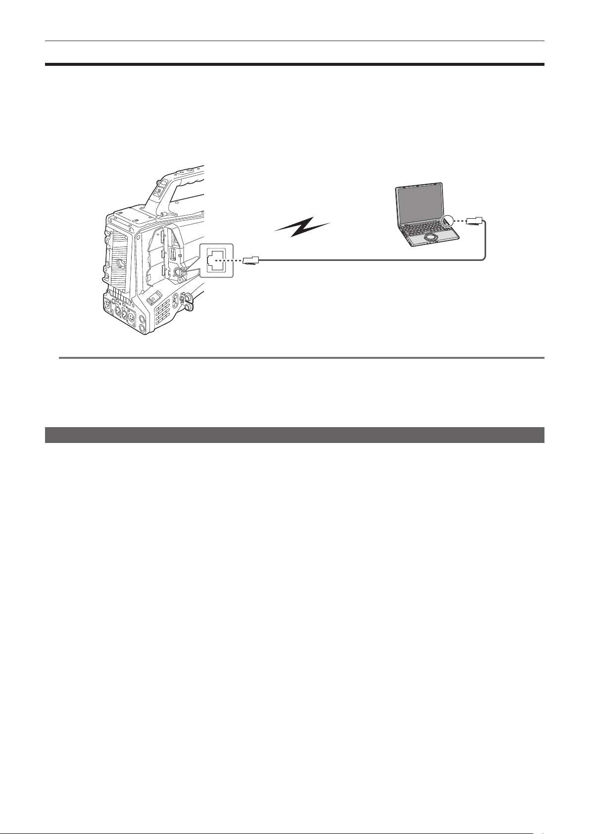
– 202 –
Chapter 9 Network Connection — Network connection
Network connection
The camera can be connected to a network via wired LAN, wireless LAN, and USB tethering.
Also, high speed network connection is possible when the bonding device is connected to a wired LAN, wireless LAN, or USB tethering.
For details on wireless module, bonding device, and iPhone/iPad and Android devices for USB tethering that can be connected, refer to the support
desk at the following website.
https://pro-av.panasonic.net/
Attach the wireless module (optional) to the <USB2.0 HOST> terminal to use a wireless LAN.
Connect a LAN cable to the <LAN> terminal on the rear side to use wired LAN.
When using USB tethering, connect an iPhone/iPad or Android device to the <USB2.0 HOST> terminal using a USB cable.
1000BASE-T/100BASE-TX/10BASE-T
IEEE802.11a/g/n/ac
@
NOTE
t For the cable to be connected to the <LAN> terminal, use a category 7 LAN cable.
t Same segment is recommended for the network which the camera and the computer is connected to.
When connecting to a different segment, check carefully before operation as there may be behavior inherent to a setting unique to the network device,
etc.
t Use the cable to connect to the <USB2.0 HOST> terminal after conrming the connection terminal of the device to connect with the camera. The
connection may become unstable depending on the length or the specication of the USB cable.
Available functions
When the camera is connected to a network, the following functions are available.
f Connecting to CX ROP application
f Streaming function
f NDI|HX function
f Linking to the Panasonic cloud service
f IP remote controlling (wired LAN only) the camera via Remote Operation Panel (AK-HRP1000G/AK-HRP1005G)
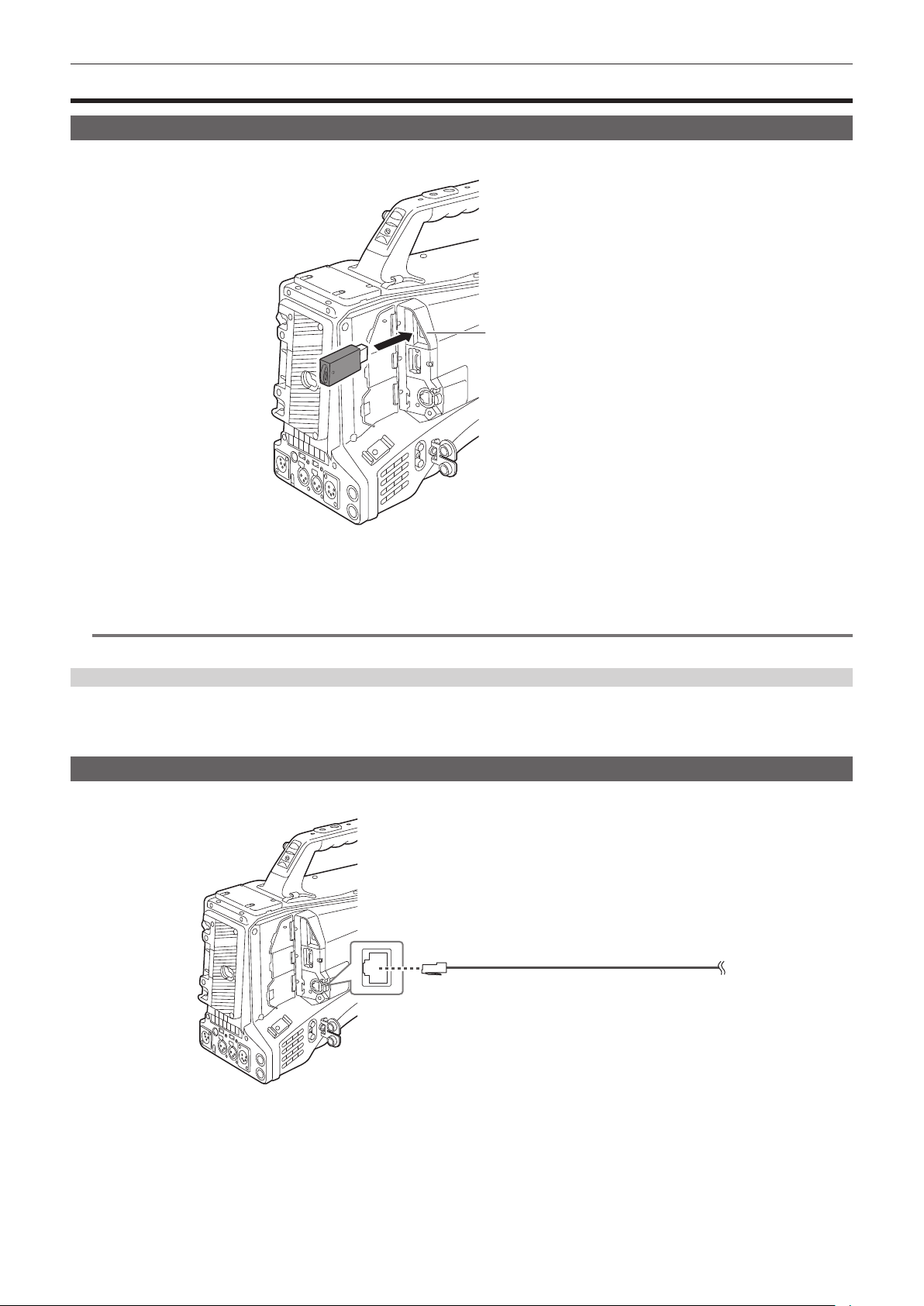
– 203 –
Chapter 9 Network Connection — Preparing for connection
Preparing for connection
For the wireless module AJ-WM50
Mount the wireless module AJ-WM50 (optional) to the camera.
<USB2.0 HOST> terminal
1
Open the <USB2.0 HOST> terminal cover.
2
Connect the wireless module to the <USB2.0 HOST> terminal.
Insert it all the way.
@
NOTE
t When removing the wireless module, pull it out straight.
Cautions when using the wireless module AJ-WM50
Read the operating instruction of the wireless module thoroughly and understand it before using.
For the latest information, visit the following website:
https://pro-av.panasonic.net/
For the wired LAN
Connect a LAN cable.
1000BASE-T/100BASE-TX/10BASE-T
1
Insert the LAN cable into the <LAN> terminal.
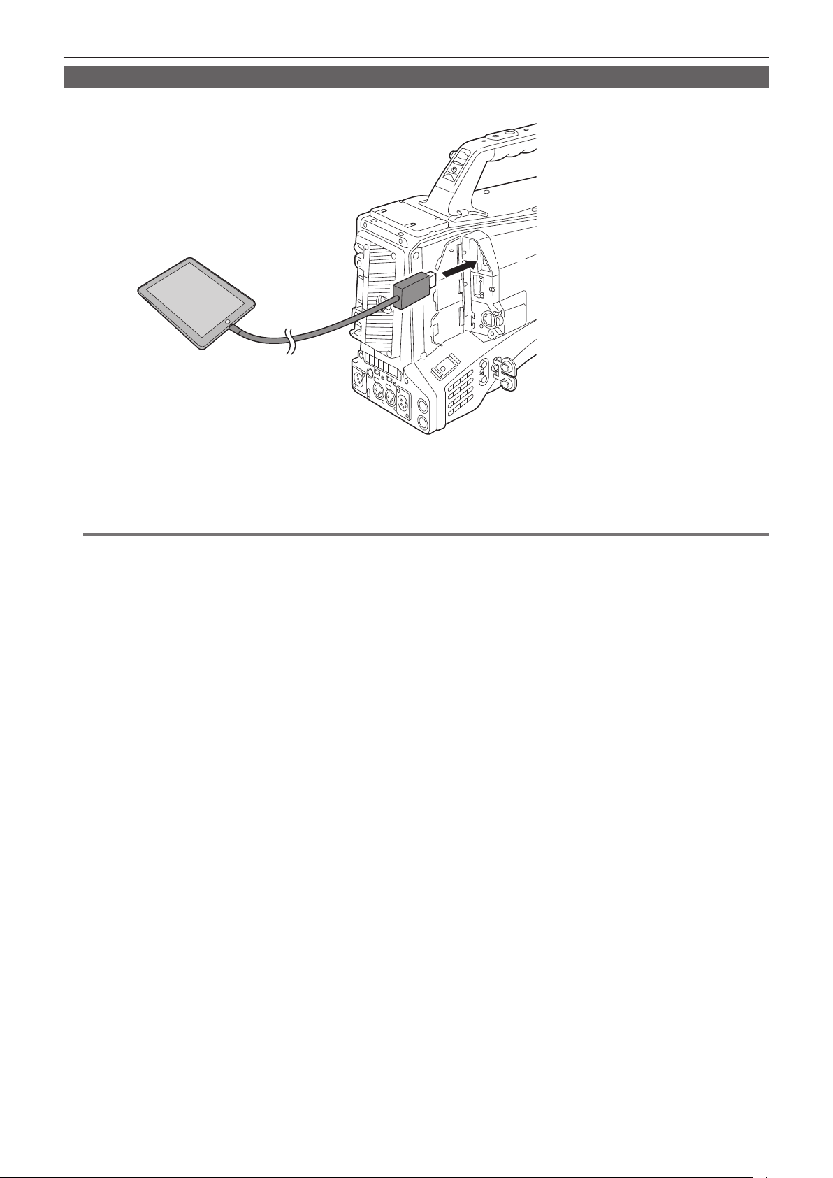
– 204 –
Chapter 9 Network Connection — Preparing for connection
For USB tethering
Connect a device (iPhone/iPad or Android device) for USB tethering to the camera.
<USB2.0 HOST> terminal
1
Open the <USB2.0 HOST> terminal cover.
2
Connect the device (iPhone/iPad or Android device) for USB tethering to the <USB2.0 HOST> terminal using a USB cable.
Insert it all the way.
@
NOTE
t When removing the USB cable, pull it out straight.
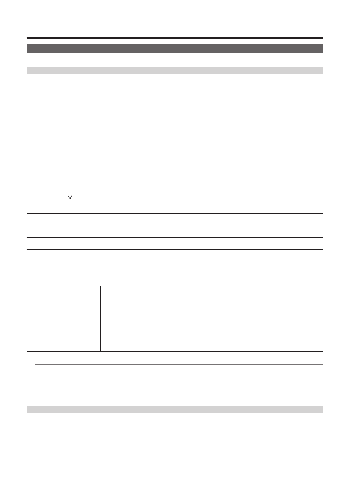
– 205 –
Chapter 9 Network Connection — Network settings
Network settings
Wireless LAN settings
This is the setting to connect with the iPhone/iPad or the Android terminal directly or to connect to the wireless access point via wireless LAN.
Direct connection ([DIRECT])
This is the setting to connect the camera to the iPhone/iPad or Android terminal directly.
The camera may restart if necessary when the setting is changed.
1
Select the [NETWORK] menu → [DEVICE SEL] → [WLAN].
2
Select the [NETWORK] menu → [WLAN PROPERTY] → [TYPE] → [DIRECT].
3
In the [NETWORK] menu → [WLAN PROPERTY], set each item as necessary.
f For details about the settings, refer to “Setting items in [WLAN PROPERTY] when set to [DIRECT]” (page 205).
4
Select the SSID of the camera from the SSID list in the iPhone/iPad or Android terminal, and enter the password (encryption key).
Display the wireless access point list screen in wireless LAN setting, and select SSID of the camera.
(Factory setting: [AJ-CX4000])
When the password conrmation screen appears, enter the password (encryption key).
For details, refer to the operating instruction of the iPhone/iPad or Android terminal.
(Factory setting: [01234567890123456789abcdef])
5
Close the menu or return to the level of the [NETWORK] menu.
6
Check the network connection.
Once connected,
is displayed on the screen of the camera.
r Setting items in [WLAN PROPERTY] when set to [DIRECT]
[SSID] Network name of the camera (SSID)
(Factory setting: [AJ-CX4000])
[BAND] Setting to switch between two communication method ([2.4GHz] or [5GHz])
(Factory setting: [2.4GHz])
[CHANNEL(2.4GHz)] Channel to be used when [BAND] is set to [2.4GHz]
(Factory setting: [AUTO])
[CHANNEL(5GHz)] Channel to be used when [BAND] is set to [5GHz]
(Factory setting: [AUTO])
[ENCRYPTION] Setting the encryption method
(Factory setting: [WPA2-AES])
[ENCRYPT KEY] WPA2 encryption key
(Factory setting: [01234567890123456789abcdef])
[IPv4 SETTING] [DHCP] Setting the DHCP function
f [OFF]: Does not use DHCP.
f [CLIENT]: Automatically acquired with the DHCP when connected by setting
[TYPE] to [INFRA(SELECT)] or [INFRA(MANUAL)]. (Cannot be selected.)
f [SERVER]: Enables the DHCP server function of the camera when
connecting with [TYPE] set to [DIRECT].
(Factory setting: [OFF])
[IP ADDRESS] IP address of the camera
(Factory setting: [192.168.0.1])
[SUBNET MASK] Subnet mask
(Factory setting: [255.255.255.0])
@
NOTE
t The startup time after turning on the power may be longer due to starting of the network.
t When changing the settings of [DEVICE SEL], the changes will not be reected until the camera is restarted. Setting screen termination may take
some time due to the restart of the network service after the setting is changed.
t Some of the items not included in the table cannot be set.
t [ENCRYPTION] will be xed to [WPA2-AES].
t Depending on the used wireless module, some of the items in [BAND], [CHANNEL(2.4GHz)], and [CHANNEL(5GHz)] may not be able to select.
Connecting to the wireless access point ([INFRA(SELECT)]/[INFRA(MANUAL)])
This is the setting to connect the camera to a wireless access point.
When connecting by searching the wireless access point (SSID)
1
Select the [NETWORK] menu → [DEVICE SEL] → [WLAN].
2
Select the [NETWORK] menu → [WLAN PROPERTY] → [TYPE] → [INFRA(SELECT)].
3
In the [NETWORK] menu → [WLAN PROPERTY], set each item as necessary.
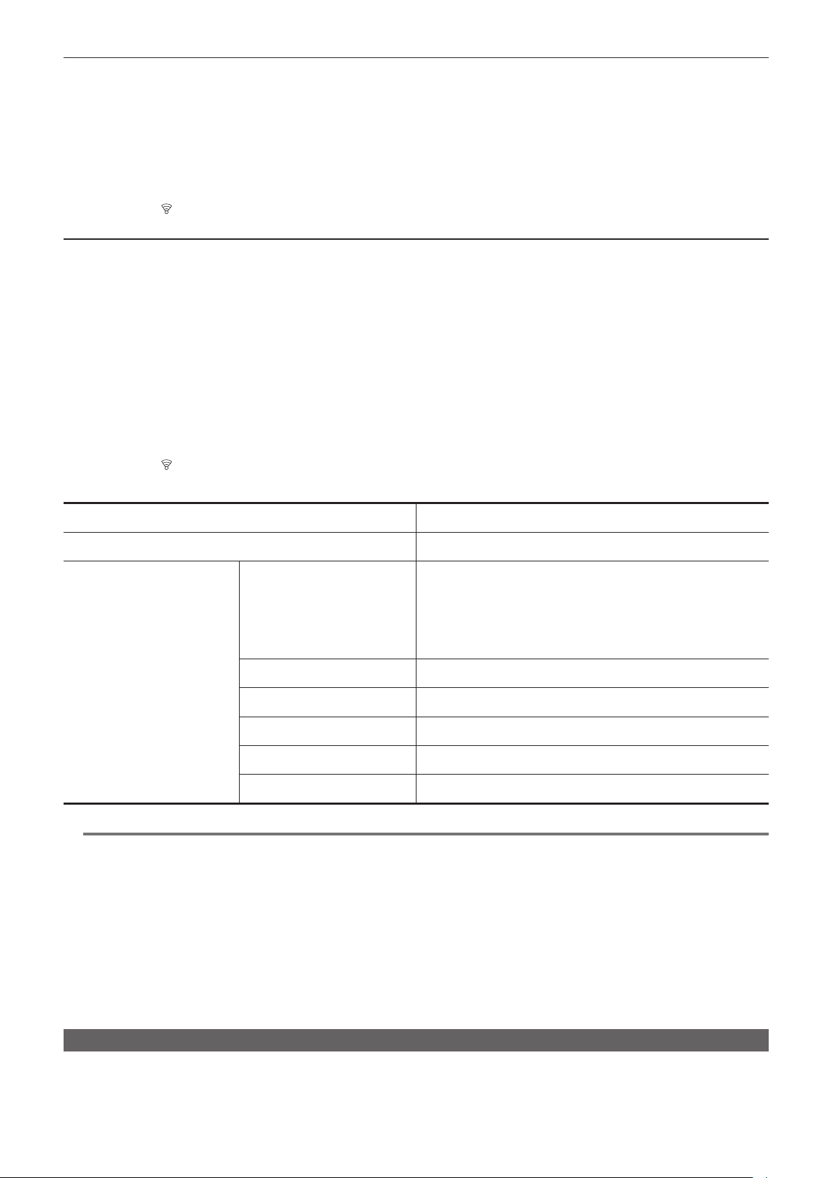
– 206 –
Chapter 9 Network Connection — Network settings
f For details about the setting items, refer to “[WLAN PROPERTY] setting items when set to [INFRA(SELECT)] or [INFRA(MANUAL)]” (page 206).
4
Select the SSID of the searched wireless access point.
Skip to step 6 if [ENCRYPT KEY] (encryption key, password) is not set.
5
If the [ENCRYPT KEY] is set, enter the password, and select [Enter].
6
Close the menu or return to the level of the [NETWORK] menu.
7
Check the network connection.
Once connected,
is displayed on the screen of the camera.
When entering the wireless access point (SSID) manually
1
Select the [NETWORK] menu → [DEVICE SEL] → [WLAN].
2
Select the [NETWORK] menu → [WLAN PROPERTY] → [TYPE] → [INFRA(MANUAL)].
3
In the [NETWORK] menu → [WLAN PROPERTY], set each item as necessary.
f For details about the setting items, refer to “[WLAN PROPERTY] setting items when set to [INFRA(SELECT)] or [INFRA(MANUAL)]” (page 206).
4
In the [NETWORK] menu → [WLAN PROPERTY] → [SSID], enter the SSID of the wireless access point to connect.
Skip to step 6 if [ENCRYPT KEY] (encryption key, password) is not set.
5
If the [ENCRYPT KEY] is set, enter the password, and select [Enter].
6
Close the menu or return to the level of the [NETWORK] menu.
7
Check the network connection.
Once connected,
is displayed on the screen of the camera.
r [WLAN PROPERTY] setting items when set to [INFRA(SELECT)] or [INFRA(MANUAL)]
[ENCRYPTION] [WPA-TKIP], [WPA-AES], [WPA2-TKIP], [WPA2-AES], [NONE]
(Factory setting: [WPA2-AES])
[ENCRYPT KEY] WPA/WPA2 encryption key
(Factory setting: [01234567890123456789abcdef])
[IPv4 SETTING] [DHCP] Setting the DHCP function
f [OFF]: Does not use DHCP.
f [CLIENT]: Automatically acquired with the DHCP when connected by setting
[TYPE] to [INFRA(SELECT)] or [INFRA(MANUAL)].
f [SERVER]: When connecting by setting [TYPE] to [DIRECT], enable the
DHCP server function of the camera. (Cannot be selected.)
(Factory setting: [OFF])
[IP ADDRESS] IP address of the camera
(Factory setting: [192.168.0.1])
[SUBNET MASK] Subnet mask
(Factory setting: [255.255.255.0])
[DEFAULT GATEWAY] Default gateway
(Factory setting: [192.168.0.254])
[PRIMARY DNS] Primary DNS server setting
(Factory setting: [0.0.0.0])
[SECONDARY DNS] Secondary DNS server setting
(Factory setting: [0.0.0.0])
@
NOTE
t The startup time after turning on the power may be longer due to starting of the network.
t When changing the settings of [DEVICE SEL], the changes will not be reected until the camera is restarted. Also, the setting screen termination may
take some time due to the restart of the network service after the setting is changed.
t ENCRYPTION in WEP is not supported.
t Some items cannot be set depending on the settings such as [DHCP].
t When [DHCP] is set to [CLIENT], some of the information acquired automatically with DHCP is displayed in the menu.
For details of the network status, conrm by selecting the [NETWORK] menu → [INFORMATION] → [STATUS].
t All of the IP address, subnet mask, and default gateway must be correctly set.
For details, contact the network administrator.
t When the default gateway or DNS is not to be used, set to [0.0.0.0].
However, DNS cannot be disabled when [DHCP] is set to [CLIENT].
t Depending on the network environment, even if [DHCP] is set to [CLIENT], entry of the DNS value manually may be required. When invalid DNS value
is entered in any other cases, the automatic assignment by DHCP will not operate properly.
Wired LAN settings
These are the settings when using a wired LAN.
1
Select the [NETWORK] menu → [DEVICE SEL] → [LAN].

– 207 –
Chapter 9 Network Connection — Network settings
2
In the [NETWORK] menu → [LAN PROPERTY], set each item as necessary.
f For details about the setting items, refer to “Setting items in [LAN PROPERTY] when set to [LAN]” (page 207).
3
Close the menu or return to the level of the [NETWORK] menu.
4
Configure the settings of the wired LAN on your device such as a computer.
For more information, refer to the operating instructions or help for the connection device.
r Setting items in [LAN PROPERTY] when set to [LAN]
[MAC ADDRESS] MAC address of the wired LAN (cannot be changed)
[IPv4 SETTING] [DHCP] Setting the DHCP function
f [OFF]: Does not use DHCP.
f [CLIENT]: Acquires automatically with DHCP.
f [SERVER]: Enables the DHCP server function of the camera.
(Factory setting: [OFF])
[IP ADDRESS] IP address of the camera
(Factory setting: [192.168.0.1])
[SUBNET MASK] Subnet mask
(Factory setting: [255.255.255.0])
[DEFAULT GATEWAY] Default gateway
(Factory setting: [192.168.0.254])
[PRIMARY DNS] Primary DNS server setting
(Factory setting: [0.0.0.0])
[SECONDARY DNS] Secondary DNS server setting
(Factory setting: [0.0.0.0])
[IPv6 SETTING] [ENABLE/DISABLE] IPv6 setting
f [ENABLE]: Uses IPv6.
f [DISABLE]: Does not use IPv6.
(Factory setting: [DISABLE])
[DHCP] Setting the DHCP function
f [OFF]: Does not use DHCP.
f [CLIENT]: Acquires automatically with DHCP.
(Factory setting: [OFF])
[IP ADDRESS] IP address of the camera
(Factory setting: [::])
[PREFIX LENGTH] Prex length settings of the subnet
(Factory setting: [64])
[DEFAULT GATEWAY] Default gateway
(Factory setting: [::])
[PRIMARY DNS] Primary DNS server
(Factory setting: [::])
[SECONDARY DNS] Secondary DNS server
(Factory setting: [::])
@
NOTE
t Some items cannot be selected depending on the settings such as [DHCP].
t The startup time after turning on the power may be longer due to starting of the network.
t When changing the settings of [DEVICE SEL], the changes will not be reected until the camera is restarted. Setting screen termination may take
some time due to the restart of the network service after the setting is changed.
t All of the IP address, subnet mask, and default gateway must be correctly set.
For details, contact the network administrator.
t Set [0.0.0.0] or [::] when not using the default gateway or DNS.
However, DNS cannot be disabled when [DHCP] is set to [CLIENT].
t Depending on the network environment, even if [DHCP] is set to [CLIENT], entry of the DNS value manually may be required. When invalid DNS value
is entered in any other cases, the automatic assignment by DHCP will not operate properly.
t DHCP and DNS may not function properly depending on the network environment.
t The IP address cannot be automatically acquired depending on the connection timing with network devices if the [NETWORK] menu → [LAN
PROPERTY] → [IPv6 SETTING] → [DHCP] → [CLIENT] is set.
In this case, reconnect the LAN cable or contact your network administrator.
USB tethering setting
These are the settings when using USB tethering.
1
Select the [NETWORK] menu → [DEVICE SEL] → [USB TETHERING].
2
Enable USB tethering (Internet sharing) in the setting screen for network on the USB tethering device connected to the camera.
Allow access of the connected device if an alert to conrm permission is displayed on the USB tethering device. Connection will not be complete
until permission is given.
3
Close the menu or return to the level of the [NETWORK] menu.

– 208 –
Chapter 9 Network Connection — Network settings
4
Check the network connection.
Once connected,
is displayed on the screen of the camera.
@
NOTE
t The startup time after turning on the power may be longer due to starting of the network.
t When changing the settings of [DEVICE SEL], the changes will not be reected until the camera is restarted. Also, the setting screen termination may
take some time due to the restart of the network service after the setting is changed.
t For details of the network status, conrm by selecting the [NETWORK] menu → [INFORMATION] → [STATUS].
t IP address, DNS, and other setting cannot be set manually when connecting to the network by USB tethering.
t The icon to show that the connection is complete indicates that communication between this camera and the USB tethering device has been
established. When the USB tethering device cannot connect to the Internet, the camera cannot connect to the Internet even if the icon that indicates
connection is complete is displayed on the camera’s screen.
t When a USB tethering device is connected to the camera using a USB cable, the USB tethering device will be charged. If a battery is used to supply
power to the camera, continuous recordable time will be shortened.
Specifying the network settings using the settings tool
Camera settings
1
From the [NETWORK] menu → [UTILITY] → [EASY IP SETTING], select anything other than [DISABLE].
2
Select the [NETWORK] menu → [UTILITY] → [EASY IP CAMERA TITLE].
3
Enter the name (nickname) of the camera.
Entered name will be the name to be displayed on the EASY IP Setup Software screen.
Installing software
Download and install EASY IP Setup Software (EasyIPSetup.exe) from the following website. (Windows)
https://pro-av.panasonic.net/
r EASY IP Setup Software (EasyIPSetup.exe)
Congure the network settings of the camera.
Performing settings of the camera using EASY IP Setup Software
The settings for the camera network can be performed using EASY IP Setup Software.
The settings for multiple cameras need to be performed on each camera.
If the settings cannot be specied using EASY IP Setup Software, specify the settings of the camera in the [NETWORK] menu.
@
NOTE
t EASY IP Setup Software can be used only when all of the following conditions are satised.
- The [NETWORK] menu → [UTILITY] → [EASY IP SETTING] is set to anything other than [DISABLE]
t The camera will not operate properly after the network settings are specied if the IP address is the same as another device on the same network.
Set a unique IP address for the camera.
t EASY IP Setup Software cannot be used from a different subnet via a router.
t Use Ver.4.25R00 or later for EASY IP Setup Software.
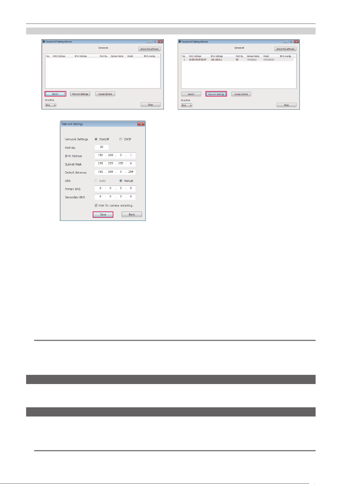
– 209 –
Chapter 9 Network Connection — Network settings
Setting procedure
Fig. 1
Fig. 3
Fig. 2
1
Start EASY IP Setup Software.
2
Click [Search]. (Fig. 1)
3
Click the MAC address/IPv4 address of the camera to set, and then click [Network settings]. (Fig. 2)
f When there are overlapping IP addresses, overlapping camera numbers are displayed in the [Duplicate IPv4 address] eld of the corresponding
camera.
4
Enter each of the network setting items, and then click [Save]. (Fig. 3)
f Network setting from EASY IP Setup Software is not possible in the following cases:
- When the [NETWORK] menu → [DEVICE SEL] → [USB TETHERING] is set
- When the [NETWORK] menu → [DEVICE SEL] → [WLAN] is set and the [NETWORK] menu → [WLAN PROPERTY] → [TYPE] → [DIRECT] is
set
f It may take approximately two minutes to complete the setting of the camera after clicking [Save].
The settings become invalid if the external DC power supply, LAN cable, or wireless module is disconnected before the settings are complete.
Specify the settings again.
@
NOTE
t The IP address assigned to the camera can be checked by clicking [Search] of EASY IP Setup Software when using the DHCP server.
t The camera does not support the IPv6 setting due to EASY IP Setup Software.
t Allow access to all of the ports for UDP when implementing a rewall (including software).
t Some of the items cannot be set on this camera.
t [View Camera Screen] displayed on Fig. 1 and Fig. 2 does not function on this camera.
Conrming the network status
The status of the camera network can be checked using the following operations.
1
Select the [NETWORK] menu → [INFORMATION] → [STATUS].
Checking the network environment
1
Select the [NETWORK] menu → [UTILITY] → [NET CHECKER].
2
Touch the [`]/[{] as necessary to confirm the results.
@
NOTE
t It may take time to display the check results as connection with external equipment is checked.

– 210 –
Chapter 9 Network Connection — Network settings
t To cancel, touch the <EXIT> button or .
t For details on the check results, contact the administrator of the network being used.
Saving the check results
Check results can be saved to a SD card as necessary.
1
Select [SAVE] when the check results are displayed.
A conrmation screen is displayed.
2
Select [SET].
The le is saved.
@
NOTE
t When a SD card is not inserted or is write-protected, [SAVE] cannot be selected.
t Save destination in the SD card and xed le name are indicated below. File will be overwritten if there already is a le.
¥PRIVATE¥MEIGROUP¥PAVCN¥SBG¥P2SD¥netchk.txt
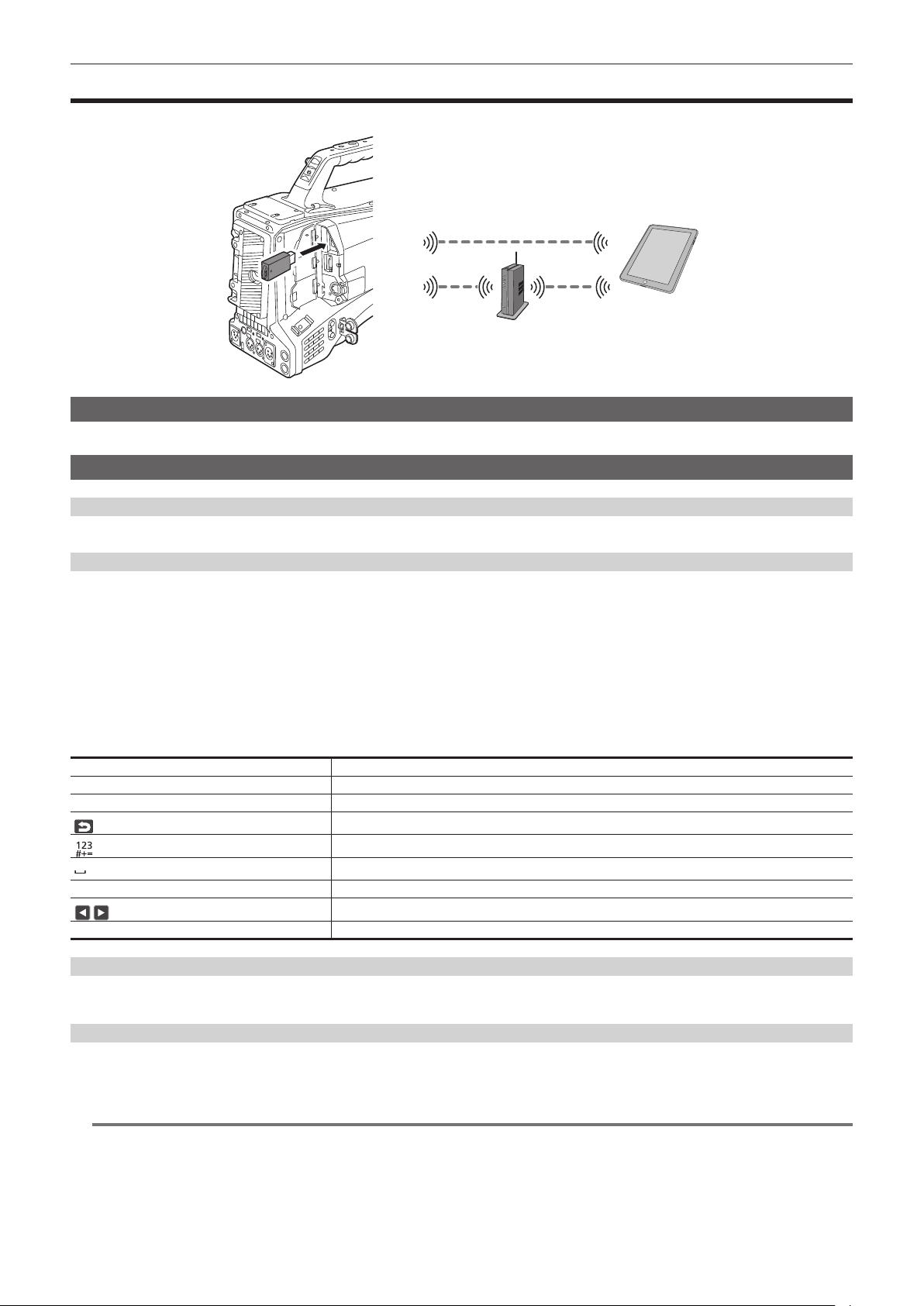
– 211 –
Chapter 9 Network Connection — Connecting to the iPhone/iPad or Android terminal
Connecting to the iPhone/iPad or Android terminal
The camera can be operated from the iPhone/iPad or Android terminal.
Mounting the wireless module
Mount the wireless module (optional) to the camera. (page 203)
Camera settings
Specifying the network settings
Specify the network settings. (page 205)
Setting the user account name and the password
1
Select the [NETWORK] menu → [IP REMOTE] → [USER ACCOUNT].
2
Enter the user account name and select [Enter].
f Enter the user account name with 31 characters or less.
3
Enter the password and select [Enter].
f Enter a password between 8 characters and 15 characters.
r To enter a character
Operation is the same as entering with a keyboard.
Icon Description of operation
[A-a] Switches between upper case and lower case. (Displayed during the text entry mode)
[@-#] Switches the type of the symbols. (Displayed during the symbol entry mode)
Returns to the previous screen. Entered character is not reected.
Switches the character to symbol/number.
Enters space (blank).
[BS] Deletes the character. Previous character is deleted when the cursor position is empty.
/
Moves the cursor to right or left.
[Enter] Completes the character entry.
Enabling the IP remote function
1
Select the [NETWORK] menu → [IP REMOTE] → [ENABLE/DISABLE] → [ENABLE].
Setting the standby port number
Depending on the environment, set the port number for standby if required.
1
Set the port number in the [NETWORK] menu → [IP REMOTE] → [CX ROP PORT].
@
NOTE
t The setting value is not reected until the [NETWORK] menu → [IP REMOTE] → [ENABLE/DISABLE] is switched to [DISABLE] once, or when the
camera is restarted.
t Number 80 and the same value as the port number set for other menu item cannot be specied.
t The TCP port set as the setting value and the UDP port set as the setting value +1 will be used.
t Inquire the administrator of the network or the device whether change is required.

– 212 –
Chapter 9 Network Connection — Connecting to the iPhone/iPad or Android terminal
Checking/deleting user accounts
1
Select the [NETWORK] menu → [IP REMOTE] → [ACCOUNT LIST].
The list of registered user accounts is displayed.
f Proceed to Step
3 to only check user accounts.
2
Select the user account to delete, and then select [SET].
A conrmation message appears.
3
Select
and end the operation.
Preparing the CX ROP app
Install the CX ROP app to the iPhone/iPad or Android terminal.
r For iPhone/iPad
f Download the CX ROP app from the App Store.
r For Android terminal
f Download the CX ROP app from the Google Play Store.
@
NOTE
t For information such as the supported OS of the CX ROP app, refer to the App Store or the Google Play Store download page.
t When using rmware of the camera Ver.3.00 or above, use the CX ROP app Ver.1.2.0 or above.
Connecting to the CX ROP application
Connect to the camera following the CX ROP app guide.
@
NOTE
t Change the connection destination port number in CX ROP app if the standby port number is changed in this camera.
t The camera cannot connect with the CX ROP app while the menu or thumbnail screen is displayed.
Operation while the CX ROP app is connected
r Operation of the camera that is connected
Following buttons and dial cannot be used.
f <MENU> button
f <THUMBNAIL> button
r Recording and playback operation while connected
f Recording can be operated by either the camera or the CX ROP app.
f Playback operation is not possible.
@
NOTE
t The content set with the remote control using the CX ROP app is reected to the camera. (Excluding setting by hard switch)
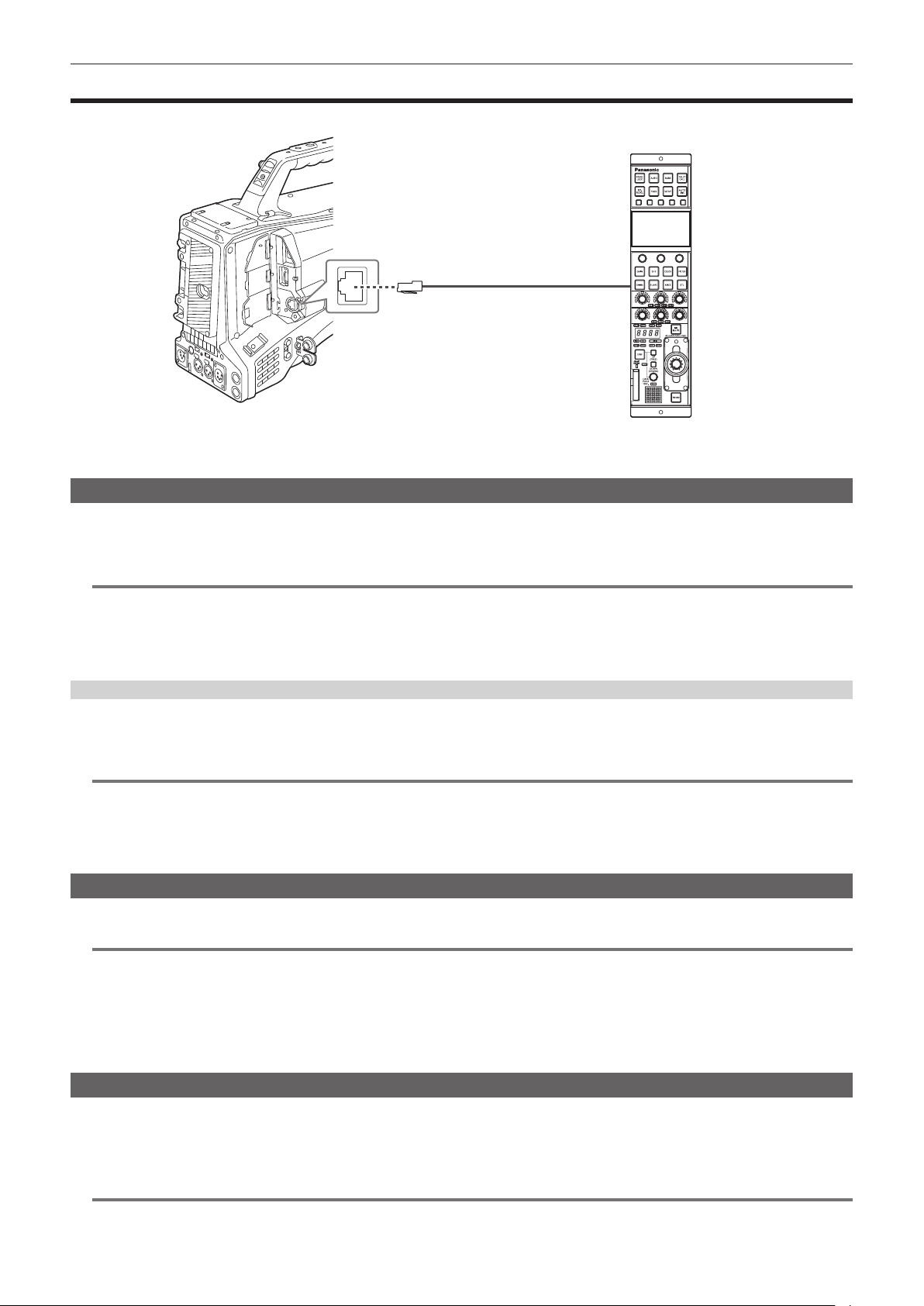
– 213 –
Chapter 9 Network Connection — Connecting with the Remote Operation Panel (AK-HRP1000G/AK-HRP1005G)
Connecting with the Remote Operation Panel (AK-HRP1000G/AK-HRP1005G)
The camera can be operated from the Remote Operation Panel AK-HRP1000G/AK-HRP1005G (optional).
1000BASE-T/100BASE-TX/10BASE-T
Remote Operation Panel
AK-HRP1005G
Camera settings
For the rmware of the camera, use Ver.3.04 or above.
For details about the camera setting, refer to “Connecting to the iPhone/iPad or Android terminal” (page 211). According to the shooting environment,
select [ENABLE] or [ENABLE(HOLD)] for the [NETWORK] menu → [IP REMOTE] → [ENABLE/DISABLE].
@
NOTE
t When the [NETWORK] menu → [IP REMOTE] → [ENABLE/DISABLE] → [ENABLE(HOLD)] is selected, connection will be preserved even if
disconnecting from the remote controller. Restrictions during connection such as the <THUMBNAIL> button not operating will remain.
To end the connection status, select the [NETWORK] menu → [IP REMOTE] → [ENABLE/DISABLE] → [DISABLE].
t Network setting and setting related to IP remote for the camera will be reected immediately after operating the menu. This may cause the connection
between the camera and remote controller to end when changing settings.
Setting the standby port number
Depending on the environment, set the port number for standby if required.
1
Set the port number in the [NETWORK] menu → [IP REMOTE] → [REMOTE CONTROL PORT].
@
NOTE
t The setting value is not reected until the [NETWORK] menu → [IP REMOTE] → [ENABLE/DISABLE] is switched to [DISABLE] once, or when the
camera is restarted.
t Number 80 and the same value as the port number set for other menu item cannot be specied.
t Only the TCP port set as the setting value will be used.
t Inquire the administrator of the network or the controller whether change is required.
Setting the Remote Operation Panel (AK-HRP1000G/AK-HRP1005G)
For details on setting the AK-HRP1000G and AK-HRP1005G, refer to Operating Instructions and Operating Guides for each.
@
NOTE
t Following information about the camera is required to connect to the AK-HRP1000G/AK-HRP1005G.
- User account name
- Password
- IP address
- Port number: The value set in the [NETWORK] menu → [IP REMOTE] → [REMOTE CONTROL PORT]
t For the rmware of the AK-HRP1000G/AK-HRP1005G, use Ver.4.82-00-005 or above.
t For details about the operation of the ROP setup software, refer to the Operating Instructions for the AK-HRP1000G and the AK-HRP1005G.
Operation during remote control
There are following restrictions when connected to a remote controller.
f Connection is not possible when displaying the thumbnail screen or during playback. In addition, <THUMBNAIL> button will not operate after
connection.
f Connection is not possible when the menu is displayed. Menu can be operated after connection.
@
NOTE
t The content set with the remote operation is reected to the setting value of the menu on the camera.

– 214 –
Chapter 9 Network Connection — Connecting with the Remote Operation Panel (AK-HRP1000G/AK-HRP1005G)
t After connection with the remote controller is ended, setting value of the menu on the camera will remain as the setting value used during connection.
However, setting items of the hard switch will return the status of each switch.

– 215 –
Chapter 9 Network Connection — Streaming function
Streaming function
You can perform streaming of audio and video currently shot with the camera over a network (wired LAN, wireless LAN, and USB tethering).
Streaming can be performed using the camera, an application software of a device connected via a network, or a server that is capable of receiving
streaming video sent from the camera.
There are two ways to start streaming: streaming from an application software and streaming from the camera. This section describes the camera's
network connection method for each method.
@
NOTE
t The streaming function cannot be simultaneously used with the recording function of the proxy data.
t Streaming stops when performing operations such as displaying the thumbnail screen or playing back clips on the camera.
t Streaming may stop when the date/time is set while streaming.
t If there is a setting that disables VFR and other streaming functions in the scene le, streaming will end due to the scene le changing.
t Take caution as streaming image may unintentionally be released depending on the system environment to stream on and setting of the service used.
Basic setting of the camera
Specifying the network settings
Specify the network settings. (page 205)
Settings for the streaming function
1
Set the [SYSTEM] menu → [FREQUENCY]/[REC FORMAT].
f For details about the setting items, refer to “Settings when using the streaming function” (page 215), “Settings when using the 4K streaming
function” (page 216).
2
Select the [NETWORK] menu → [NETWORK FUNC] → [STREAMING] or [STREAMING(4K)].
Streaming function is enabled.
3
Select the protocol with the [NETWORK] menu → [STREAMING] → [STREAMING PROTOCOL].
4
In the [NETWORK] menu → [STREAMING] → [STREAMING FORMAT], set the format when streaming.
f For details about the setting items, refer to “Settings when using the streaming function” (page 215), “Settings when using the 4K streaming
function” (page 216).
5
Set the setting corresponding to the selected protocol.
f For details on each protocol, refer to “Setting for each protocol and starting the streaming” (page 217).
@
NOTE
t The streaming function can be used when all of the following conditions are satised.
- The menu has been set according to “Settings when using the streaming function” (page 215)
(This cannot be used when set to UHD)
- Some special recording functions are disabled
- The [RECORDING] menu → [PROXY SETTING] → [PROXY REC] → [OFF] is set
t Recording and displaying of the thumbnail are not possible when [STREAMING(4K)] is selected.
t The 4K streaming function can be used when all of the following conditions are satised.
- The [SYSTEM] menu → [FILE FORMAT] is set to [MOV]
- The menu is set in accordance to “Settings when using the 4K streaming function” (page 216)
(This cannot be used when set to anything other than UHD)
- VFR and some special recording functions are disabled
t When the [SCENE FILE] menu → [GAMMA MODE SEL] is set to [HLG], video is streamed after converting from high dynamic range to standard
dynamic range.
t When the [SYSTEM] menu → [COLOR SETTING] is set to [V-Log], video is streamed after converting from V-Log to V-709.
r Settings when using the streaming function
The item that can be selected varies depending on the [STREAMING PROTOCOL] settings.
f For [SRT CLIENT] or [SRT LISTENER]: Only the steaming format with “*” in the table can be selected.
[SYSTEM] menu
[NETWORK] menu → [STREAMING]
[FREQUENCY] [REC FORMAT] [STREAMING FORMAT]
[59.94Hz] [1080-59.94p/AVC-I100]
[1080-59.94p/AVC-I422]
[1080-59.94p/AVC-G25]
[1080-59.94p/AVC-G12]
[1080-59.94p/422LongGOP 100M]
[1080-59.94p/422ALL-I 200M]
*[1920×1080-60fps 24M]
*[1920×1080-60fps 20M]
*[1920×1080-60fps 16M]
*[1280×720-60fps 14M]
*[1280×720-60fps 8M]
*[1280×720-60fps 3M]
[640×360-30fps 4M]
[640×360-30fps 1.5M]
[640×360-30fps 0.7M] (Factory setting)
[320×180-30fps 4M]
[320×180-30fps 1.5M]
[320×180-30fps 0.5M]

– 216 –
Chapter 9 Network Connection — Streaming function
[SYSTEM] menu
[NETWORK] menu → [STREAMING]
[FREQUENCY] [REC FORMAT] [STREAMING FORMAT]
[1080-59.94i/AVC-I200]
[1080-59.94i/AVC-I100]
[1080-59.94i/AVC-I50]
[1080-59.94i/AVC-G50]
[1080-59.94i/AVC-G25]
[1080-59.94i/AVC-G12]
[1080-29.97p/422LongGOP 50M]
[1080-29.97p/422ALL-I 100M]
[1080-59.94i/422LongGOP 50M]
[1080-59.94i/422ALL-I 100M]
*[1920×1080-30fps 14M]
*[1920×1080-30fps 6M]
*[1920×1080-30fps 1M]
*[1280×720-30fps 8M]
*[1280×720-30fps 2M]
*[1280×720-30fps 1M]
[640×360-30fps 4M]
[640×360-30fps 1.5M]
[640×360-30fps 0.7M] (Factory setting)
[320×180-30fps 4M]
[320×180-30fps 1.5M]
[320×180-30fps 0.5M]
[1080-23.98p/422LongGOP 50M]
[1080-23.98p/422ALL-I 100M]
[1920×1080-24fps 14M]
[1920×1080-24fps 6M]
[1920×1080-24fps 1M] (Factory setting)
[720-59.94p/AVC-I200]
[720-59.94p/AVC-I100]
[720-59.94p/AVC-I50]
[720-59.94p/AVC-G50]
[720-59.94p/AVC-G25]
[720-59.94p/AVC-G12]
*[1280×720-60fps 14M]
*[1280×720-60fps 8M]
*[1280×720-60fps 3M]
[640×360-30fps 4M]
[640×360-30fps 1.5M]
[640×360-30fps 0.7M] (Factory setting)
[320×180-30fps 4M]
[320×180-30fps 1.5M]
[320×180-30fps 0.5M]
[50.00Hz] [1080-50.00p/AVC-I100]
[1080-50.00p/AVC-I422]
[1080-50.00p/AVC-G25]
[1080-50.00p/AVC-G12]
[1080-50.00p/422LongGOP 100M]
[1080-50.00p/422ALL-I 200M]
*[1920×1080-50fps 24M]
*[1920×1080-50fps 20M]
*[1920×1080-50fps 16M]
*[1280×720-50fps 14M]
*[1280×720-50fps 8M]
*[1280×720-50fps 3M]
[640×360-25fps 4M]
[640×360-25fps 1.5M]
[640×360-25fps 0.7M] (Factory setting)
[320×180-25fps 4M]
[320×180-25fps 1.5M]
[320×180-25fps 0.5M]
[1080-50.00i/AVC-I200]
[1080-50.00i/AVC-I100]
[1080-50.00i/AVC-I50]
[1080-50.00i/AVC-G50]
[1080-50.00i/AVC-G25]
[1080-50.00i/AVC-G12]
[1080-25.00p/422LongGOP 50M]
[1080-25.00p/422ALL-I 100M]
[1080-50.00i/422LongGOP 50M]
[1080-50.00i/422ALL-I 100M]
*[1920×1080-25fps 14M]
*[1920×1080-25fps 6M]
*[1920×1080-25fps 1M]
*[1280×720-25fps 8M]
*[1280×720-25fps 2M]
*[1280×720-25fps 1M]
[640×360-25fps 4M]
[640×360-25fps 1.5M]
[640×360-25fps 0.7M] (Factory setting)
[320×180-25fps 4M]
[320×180-25fps 1.5M]
[320×180-25fps 0.5M]
[720-50.00p/AVC-I200]
[720-50.00p/AVC-I100]
[720-50.00p/AVC-I50]
[720-50.00p/AVC-G50]
[720-50.00p/AVC-G25]
[720-50.00p/AVC-G12]
*[1280×720-50fps 14M]
*[1280×720-50fps 8M]
*[1280×720-50fps 3M]
[640×360-25fps 4M]
[640×360-25fps 1.5M]
[640×360-25fps 0.7M] (Factory setting)
[320×180-25fps 4M]
[320×180-25fps 1.5M]
[320×180-25fps 0.5M]
r Settings when using the 4K streaming function
f The item that can be selected varies depending on the [STREAMING PROTOCOL] settings.
-For [SRT CLIENT] or [SRT LISTENER]: The recording format/streaming format starting with 2160-23.98p is not supported.
-For [RTMP(S)]: The streaming format starting with H.265 is not supported.
f When using RTMPS or when SRT encryption is enabled, only the streaming format equal to or less than 25 Mbps can be selected.
[SYSTEM] menu
[NETWORK] menu → [STREAMING]
[FREQUENCY] [REC FORMAT] [STREAMING FORMAT]
[59.94Hz] [2160-59.94p/420LongGOP 150M]
[2160-59.94p/HEVC LongGOP 200M]
[2160-59.94p/HEVC LongGOP 100M]
[H.265_3840×2160-60fps 75M]
[H.265_3840×2160-60fps 50M]
[H.265_3840×2160-60fps 25M]
[H.265_3840×2160-60fps 12M]
[H.265_3840×2160-60fps 8M]
[H.264_3840×2160-60fps 75M]
[H.264_3840×2160-60fps 50M]
[H.264_3840×2160-60fps 25M]
[H.264_3840×2160-60fps 12M] (Factory setting)

– 217 –
Chapter 9 Network Connection — Streaming function
[SYSTEM] menu
[NETWORK] menu → [STREAMING]
[FREQUENCY] [REC FORMAT] [STREAMING FORMAT]
[2160-29.97p/420LongGOP 100M]
[2160-29.97p/HEVC LongGOP 150M]
[2160-29.97p/422LongGOP 150M]
[2160-29.97p/422ALL-I 400M]
[H.265_3840×2160-30fps 75M]
[H.265_3840×2160-30fps 50M]
[H.265_3840×2160-30fps 25M]
[H.265_3840×2160-30fps 12M]
[H.265_3840×2160-30fps 8M]
[H.264_3840×2160-30fps 75M]
[H.264_3840×2160-30fps 50M]
[H.264_3840×2160-30fps 25M]
[H.264_3840×2160-30fps 12M] (Factory setting)
[2160-23.98p/420LongGOP 100M]
[2160-23.98p/HEVC LongGOP 150M]
[2160-23.98p/422LongGOP 150M]
[2160-23.98p/422ALL-I 400M]
[H.265_3840×2160-24fps 75M]
[H.265_3840×2160-24fps 50M]
[H.265_3840×2160-24fps 25M]
[H.265_3840×2160-24fps 12M]
[H.265_3840×2160-24fps 8M]
[H.264_3840×2160-24fps 75M]
[H.264_3840×2160-24fps 50M]
[H.264_3840×2160-24fps 25M]
[H.264_3840×2160-24fps 12M] (Factory setting)
[50.00Hz] [2160-50.00p/420LongGOP 150M]
[2160-50.00p/HEVC LongGOP 200M]
[2160-50.00p/HEVC LongGOP 100M]
[H.265_3840×2160-50fps 75M]
[H.265_3840×2160-50fps 50M]
[H.265_3840×2160-50fps 25M]
[H.265_3840×2160-50fps 12M]
[H.265_3840×2160-50fps 8M]
[H.264_3840×2160-50fps 75M]
[H.264_3840×2160-50fps 50M]
[H.264_3840×2160-50fps 25M]
[H.264_3840×2160-50fps 12M] (Factory setting)
[2160-25.00p/420LongGOP 100M]
[2160-25.00p/HEVC LongGOP 150M]
[2160-25.00p/422LongGOP 150M]
[2160-25.00p/422ALL-I 400M]
[H.265_3840×2160-25fps 75M]
[H.265_3840×2160-25fps 50M]
[H.265_3840×2160-25fps 25M]
[H.265_3840×2160-25fps 12M]
[H.265_3840×2160-25fps 8M]
[H.264_3840×2160-25fps 75M]
[H.264_3840×2160-25fps 50M]
[H.264_3840×2160-25fps 25M]
[H.264_3840×2160-25fps 12M] (Factory setting)
Setting for each protocol and starting the streaming
RTMP(S)
1
Select the [NETWORK] menu → [STREAMING] → [STREAMING PROTOCOL] → [RTMP(S)].
2
Set the destination.
For details of setting the streaming destination, refer to “Setting of the destination” (page 219).
3
Select the [NETWORK] menu → [STREAMING] → [START] → [ON].
If the camera is connected to the transmission destination through a network, the camera starts the transmission of streaming video.
f To stop the transmission of the streaming image, select the [NETWORK] menu → [STREAMING] → [START] → [OFF].
@
NOTE
t The H.265 format cannot be selected in the 4K streaming.
t [START] menu cannot be selected when the streaming cannot be started due to reasons such as the network is not connected, etc.
t Starting/stopping of the streaming from the camera can be assigned to the USER button. (page 136)
Streaming cannot be started by pressing the USER button when the menu or the thumbnail screen is displayed.
t IPv6 cannot be used for RTMP(S).
t For settings such as URL, refer to the manual for each streaming service.
t Streaming may not be possible depending on the operating condition of the streaming service.
t Setting of [RECEIVER URL] is not possible when [DATA TYPE] is set to [CLOUD]. Set this after performing the operation for [CLEAR (MEMORY)]
once.
RTSP
Start the streaming with an operation of the application software or device at the receiving side (referred to as “receiving side” hereinafter).
1
Select the [NETWORK] menu → [STREAMING] → [STREAMING PROTOCOL] → [RTSP] in the camera.
2
Set the standby port with the [NETWORK] menu → [STREAMING] → [RTSP SETTING] → [LISTEN PORT] on the camera if
required.
3
Specify the IP address and the path of the camera as following on the receiving side, and start streaming.
rtsp://(IP address):(Port number)/stream

– 218 –
Chapter 9 Network Connection — Streaming function
@
NOTE
t Stop the streaming with the operation in the receiving side.
t For details about the operations to start streaming from the application software, refer to the manual for the receiving side.
t Streaming cannot be started while the thumbnail screen is displayed.
r Streaming with multicast
One streaming can be distributed to multiple receivers via supported router, etc., when the multicast function is used.
1
Select the [NETWORK] menu → [STREAMING] → [RTSP SETTING] → [MULTICAST] → [ENABLE].
2
Select the [NETWORK] menu → [STREAMING], and specify [MULTICAST ADDRESS] and [MULTICAST PORT].
f Set [MULTICAST ADDRESS] within following range.
IPv4: 224.0.1.0 to 239.255.255.254
IPv6: Multicast address starting with FF
f Set [MULTICAST PORT] within the range of 1024 to 50000.
3
Specify the address of the camera and start streaming with the application software.
@
NOTE
t Depending on the specication of the device receiving streaming and the connected router, quality of the video image may not be preserved. When
streaming by multicast, contact the administrator of the network being used and prepare appropriate communication environment.
t Disable the LAN card not to be used when receiving the multicast image to be displayed on a computer with multiple LAN cards installed.
t Range of streaming can be adjusted with the [NETWORK] menu → [STREAMING] → [RTSP SETTING] → [TTL/HOP LIMIT]. For details, contact the
network administrator.
SRT CLIENT
1
Select the [NETWORK] menu → [STREAMING] → [STREAMING PROTOCOL] → [SRT CLIENT].
2
Set the destination.
For details of setting the streaming destination, refer to “Setting of the destination” (page 219).
3
Select the [NETWORK] menu → [STREAMING] → [START] → [ON].
If the camera is connected to the transmission destination through a network, the camera starts the transmission of streaming video.
f To stop the transmission of the streaming image, select the [NETWORK] menu → [STREAMING] → [START] → [OFF].
@
NOTE
t Streaming in 23.98 Hz is not possible with SRT.
t [START] menu cannot be selected when the streaming cannot be started due to reasons such as the network is not connected, etc.
t Starting/stopping of the streaming from the camera can be assigned to the USER button. (page 136)
t Streaming cannot be started by pressing the USER button when the thumbnail screen is displayed.
t For settings such as URL, refer to the manual for each streaming service.
t Streaming may not be possible depending on the operating condition of the streaming service.
t Range of streaming can be adjusted with the [NETWORK] menu → [STREAMING] → [SRT SETTING] → [TTL/HOP LIMIT]. For details, contact the
network administrator.
t Depending on the environment, the delay time can be adjusted with the [NETWORK] menu → [STREAMING] → [SRT SETTING] → [LATENCY]. For
details, contact the network administrator.
t Settings of [DEST URL], [STREAM ID], [ENCRYPTION], and [PASSPHRASE] are not possible when [DATA TYPE] is set to [CLOUD]. Set this after
performing the operation for [CLEAR (MEMORY)] once.
SRT LISTENER
Start the streaming with an operation of the application software or device at the receiving side (referred to as “receiving side” hereinafter).
1
Select the [NETWORK] menu → [STREAMING] → [STREAMING PROTOCOL] → [SRT LISTENER] in the camera.
2
Set following items with the [NETWORK] menu → [STREAMING] → [SRT SETTING] on the camera.
f Set the standby port with [LISTEN PORT].
f If the streaming data is to be encrypted, select the encryption method in [ENCRYPTION], and enter the passphrase in [PASSPHRASE].
3
Specify the IP address and the stream ID of the camera as following on the receiving side, and start streaming.
srt://(IP address):(Port number)
f The stream ID is xed to following value in the SRT LISTENER mode.
#!::m=publish,r=PanasonicStream
@
NOTE
t Streaming in 23.98 Hz is not possible with SRT.
t Stop the streaming with the operation in the receiving side.
t For details about the operations to start streaming from the application software, refer to the manual for each application software.
t Range of streaming can be adjusted with the [NETWORK] menu → [STREAMING] → [SRT SETTING] → [TTL/HOP LIMIT]. For details, contact the
network administrator.
t Depending on the environment, the delay time can be adjusted with the [NETWORK] menu → [STREAMING] → [SRT SETTING] → [LATENCY]. For
details, contact the network administrator.
t When the passphrase is blank, communication is performed without encryption even if [ENCRYPTION] is set to anything other than [OFF].

– 219 –
Chapter 9 Network Connection — Streaming function
t Streaming cannot be started while the thumbnail screen is displayed.
Management of setting information
Setting of the destination
Information regarding the destination can be set or referenced.
Setting the destination with the camera menu
r For RTMP(S)
1
Select the [NETWORK] menu → [STREAMING] → [CONNECTION INFO.] → [MEMORY].
2
Enter the destination URL in the [NETWORK] menu → [STREAMING] → [RTMP(S) RECEIVER URL].
f Enter the destination URL in following format.
- rtmp://(server URL):(port number)/(path)/(stream key)
- rtmps://(server URL):(port number)/(path)/(stream key)
@
NOTE
t In general, a parameter for the stream key is required for URL, but the stream key may be contained as a part of the path depending on the service.
For details, refer to the manual for each streaming service.
t When using RTMPS, only the streaming format equal to or less than 25 Mbps can be selected.
r For SRT CLIENT
1
Select the [NETWORK] menu → [STREAMING] → [CONNECTION INFO.] → [MEMORY].
2
Set following items with the [NETWORK] menu → [STREAMING] → [SRT SETTING].
f Enter the destination URL in [DEST URL] in following format.
srt://(server URL):(Port number)/(Path)
f Enter the stream ID in [STREAM ID].
f If the streaming data is to be encrypted, select the encryption method in [ENCRYPTION], and enter the passphrase in [PASSPHRASE].
@
NOTE
t In general, a parameter for the stream ID is required for URL, but the stream ID may be contained as a part of the path depending on the service. For
details, refer to the manual for each streaming service.
t When the SRT encryption is enabled, only the streaming format equal to or less than 25 Mbps can be selected.
t When the passphrase is blank, communication is performed without encryption even if [ENCRYPTION] is set to anything other than [OFF].
Referencing destination from the memory card
1
Insert the memory card with the destination information saved into the card slot selected in the [OTHERS] menu → [FILE] →
[SLOT FOR LOAD/SAVE].
2
Select the [NETWORK] menu → [STREAMING] → [CONNECTION INFO.] → [SD CARD].
@
NOTE
t If the setting information in the memory card is not information for the selected protocol or the cloud, it will be treated as no setting.
Saving the destination information on the memory card
1
Insert the memory card formatted in the camera into the card slot selected in the [OTHERS] menu → [FILE] → [SLOT FOR LOAD/
SAVE].
2
Select the [NETWORK] menu → [STREAMING] → [SAVE (SD CARD)].
3
Select [YES] when the confirmation message is displayed.
@
NOTE
t Only items saved are the ones that are used in the destination setting.
t The name of the le in the memory card to save the destination information cannot be changed.
t The le with the destination information saved on the memory card is encrypted.
t Only the selected protocol settings are saved if the protocol is RTMP(S) or SRT CLIENT.
t Save is not possible when [DATA TYPE] is set to [CLOUD].
t Save is not possible when the starting character string of the [RECEIVER URL] or the [DEST URL] (“rtmp://”, etc.) is not set correctly.
Loading destination information from the memory card
1
Insert the memory card with the destination information saved into the card slot selected in the [OTHERS] menu → [FILE] →
[SLOT FOR LOAD/SAVE].
2
Select the [NETWORK] menu → [STREAMING] → [LOAD (SD CARD)].
3
Select [YES] when the confirmation message is displayed.
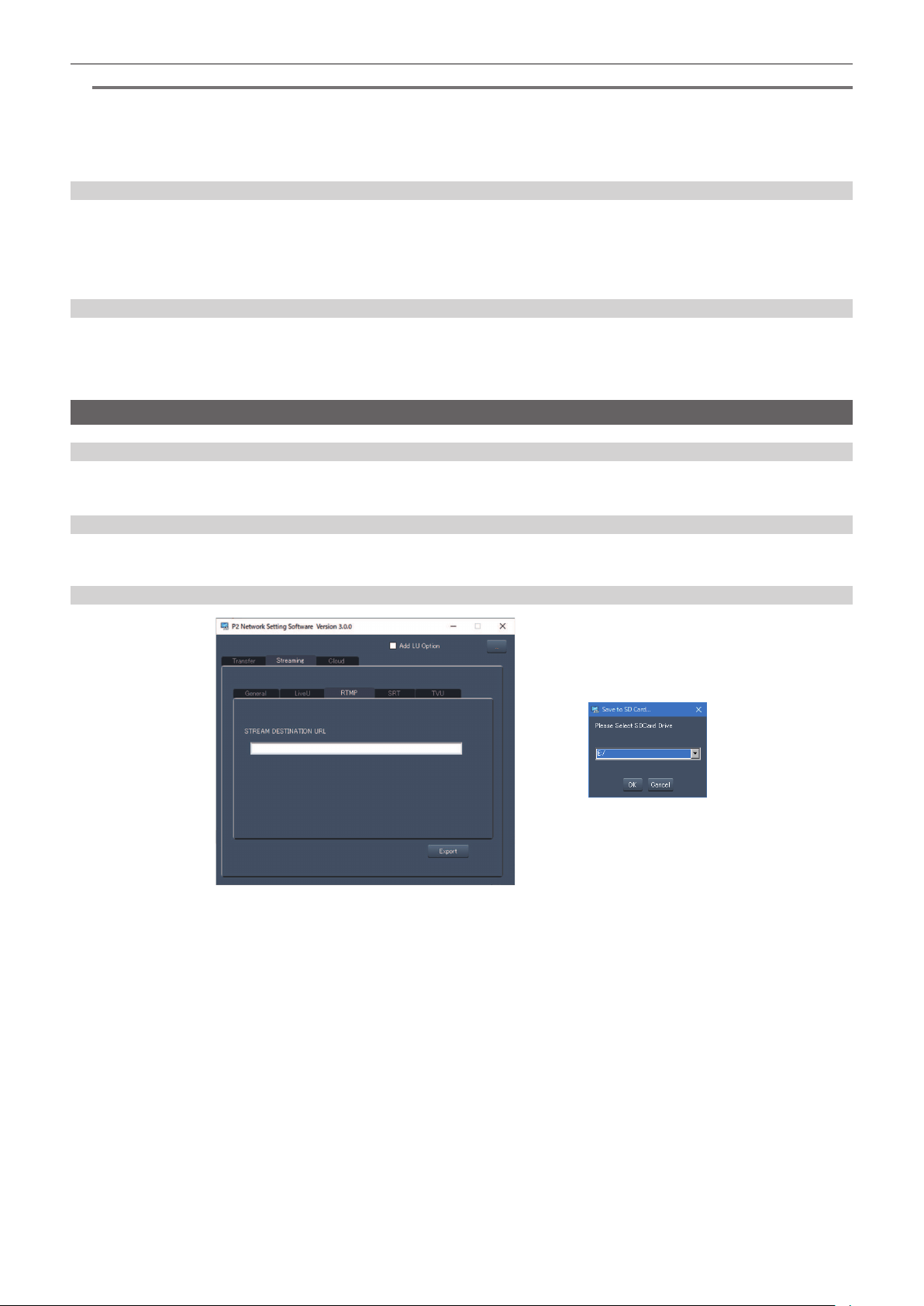
– 220 –
Chapter 9 Network Connection — Streaming function
@
NOTE
t The name of the le to load destination information saved on the memory card cannot be selected.
t The setting information that can be loaded (referenced) by the camera is as follows.
- Information saved with the camera
- Setting le created with the P2 Network Setting software (page 220)
- Prole downloaded from the cloud service (page 224)
Clearing the destination information
1
Select the [NETWORK] menu → [STREAMING] → [CLEAR (MEMORY)].
The setting regarding the destination information is cleared.
f The setting information for the cloud service is also cleared.
f The destination URL information set in the cloud service is also cleared. (page 224)
Stopping streaming of video
Stop the streaming in following procedure if the streaming was started with the operation of the camera.
1
Select the [NETWORK] menu → [STREAMING] → [START] → [OFF].
f If a start/stop of streaming is assigned to a USER button, streaming can also be stopped with the USER button.
Entering the setting using the setting tool
Installing software
Download and expand the P2 Network Setting software for Windows from the following website.
https://pro-av.panasonic.net/
Creating the SD card for setting using the P2 Network Setting software
The SD card created with this software can be used to load into the camera menu or as the reference destination when the [NETWORK] menu →
[STREAMING] → [CONNECTION INFO.] → [SD CARD] is selected.
RTMP(S) setting procedure
Fig. 1 Fig. 2
1
Start the P2 Network Setting software. (Fig. 1)
2
Select the [Streaming] tab → [RTMP] tab.
3
Enter the destination URL in [STREAM DESTINATION URL].
4
Click [Export] and select the destination in the drive selection dialog, and then click [OK]. (Fig. 2)
f This cannot be saved to anything other than a removable drive.

– 221 –
Chapter 9 Network Connection — Streaming function
SRT CLIENT setting procedure
Fig. 1 Fig. 2
1
Start the P2 Network Setting software. (Fig. 1)
2
Select the [Streaming] tab → [SRT] tab.
3
Enter the destination URL in [STREAM DEST. URL].
4
Enter the stream ID in [STREAM ID].
5
To encrypt, select Encryption and enter the PASS PHRASE.
6
Click [Export] and select the destination in the drive selection dialog, and then click [OK]. (Fig. 2)
f This cannot be saved to anything other than a removable drive.
@
NOTE
t When setting the SRT CLIENT, use the P2 Network Setting software Ver.3.00 or later.

– 222 –
Chapter 9 Network Connection — NDI|HX function
NDI|HX function
The camera can be connected to a NDI|HX compatible switchers made by NewTek.
@
NOTE
t Purchasing of the activation key is required to use the NDI|HX function. For details, refer to the website of NewTek.
t For details of each operation, refer to the operating instruction of the NDI|HX compatible switcher.
t The following functions cannot be used when the NDI|HX function is enabled. Some of the menu items related to those functions cannot be selected
as well.
- Recording function
- Functions of the playback system including the thumbnail display
- Wireless LAN
- USB tethering
Camera settings
Specifying the network settings
Sets the wired LAN setting. (page 206)
Setting for the NDI|HX function
1
Set the [SYSTEM] menu → [FREQUENCY]/[REC FORMAT].
f For details about the setting items, refer to “Settings when using the NDI|HX function” (page 222).
2
Select the [NETWORK] menu → [NETWORK FUNC] → [NDI|HX].
The NDI|HX function is selected. The camera will automatically restart.
3
Set the streaming format with the [NETWORK] menu → [NDI|HX] → [STREAMING FORMAT].
This cannot be used when set to UHD.
@
NOTE
t NDI|HX function can be used when all of the following conditions are satised.
- The menu has been set according to “Settings when using the NDI|HX function” (page 222)
- Some special recording functions are disabled
t When the NDI|HX function is enabled, it is switched to the [NETWORK] menu → [UTILITY] → [EASY IP SETTING] → [UNLIMITED].
t When the [SCENE FILE] menu → [GAMMA MODE SEL] is set to [HLG], video is streamed after converting from high dynamic range to standard
dynamic range.
t When the [SYSTEM] menu → [COLOR SETTING] is set to [V-Log], video is streamed after converting from V-Log to V-709.
r Settings when using the NDI|HX function
[SYSTEM] menu
[NETWORK] menu → [NDI|HX]
[FREQUENCY] [REC FORMAT] [STREAMING FORMAT]
[59.94Hz] [1080-59.94p/AVC-I100]
[1080-59.94p/AVC-I422]
[1080-59.94p/AVC-G25]
[1080-59.94p/AVC-G12]
[1080-59.94p/422LongGOP 100M]
[1080-59.94p/422ALL-I 200M]
[1920×1080-60fps 24M]
[1920×1080-60fps 16M]
[1920×1080-60fps 10M] (Factory setting)
[1920×1080-60fps 8M]
[1280×720-60fps 14M]
[1280×720-60fps 10M]
[1280×720-60fps 6M]
[1080-59.94i/AVC-I200]
[1080-59.94i/AVC-I100]
[1080-59.94i/AVC-I50]
[1080-59.94i/AVC-G50]
[1080-59.94i/AVC-G25]
[1080-59.94i/AVC-G12]
[1080-29.97p/422LongGOP 50M]
[1080-29.97p/422ALL-I 100M]
[1080-59.94i/422LongGOP 50M]
[1080-59.94i/422ALL-I 100M]
[1920×1080-30fps 14M]
[1920×1080-30fps 10M] (Factory setting)
[1920×1080-30fps 6M]
[1280×720-30fps 8M]
[1280×720-30fps 4M]
[1280×720-30fps 2M]
[720-59.94p/AVC-I200]
[720-59.94p/AVC-I100]
[720-59.94p/AVC-I50]
[720-59.94p/AVC-G50]
[720-59.94p/AVC-G25]
[720-59.94p/AVC-G12]
[1280×720-60fps 14M]
[1280×720-60fps 10M] (Factory setting)
[1280×720-60fps 6M]
[50.00Hz] [1080-50.00p/AVC-I100]
[1080-50.00p/AVC-I422]
[1080-50.00p/AVC-G25]
[1080-50.00p/AVC-G12]
[1080-50.00p/422LongGOP 100M]
[1080-50.00p/422ALL-I 200M]
[1920×1080-50fps 24M]
[1920×1080-50fps 16M]
[1920×1080-50fps 10M] (Factory setting)
[1920×1080-50fps 8M]
[1280×720-50fps 14M]
[1280×720-50fps 10M]
[1280×720-50fps 6M]

– 223 –
Chapter 9 Network Connection — NDI|HX function
[SYSTEM] menu
[NETWORK] menu → [NDI|HX]
[FREQUENCY] [REC FORMAT] [STREAMING FORMAT]
[1080-50.00i/AVC-I200]
[1080-50.00i/AVC-I100]
[1080-50.00i/AVC-I50]
[1080-50.00i/AVC-G50]
[1080-50.00i/AVC-G25]
[1080-50.00i/AVC-G12]
[1080-25.00p/422LongGOP 50M]
[1080-25.00p/422ALL-I 100M]
[1080-50.00i/422LongGOP 50M]
[1080-50.00i/422ALL-I 100M]
[1920×1080-25fps 14M]
[1920×1080-25fps 10M] (Factory setting)
[1920×1080-25fps 6M]
[1280×720-25fps 8M]
[1280×720-25fps 4M]
[1280×720-25fps 2M]
[720-50.00p/AVC-I200]
[720-50.00p/AVC-I100]
[720-50.00p/AVC-I50]
[720-50.00p/AVC-G50]
[720-50.00p/AVC-G25]
[720-50.00p/AVC-G12]
[1280×720-50fps 14M]
[1280×720-50fps 10M] (Factory setting)
[1280×720-50fps 6M]
Enabling the NDI|HX function
Perform the setting for the NDI|HX function, and then enable the NDI|HX function referring to the information in the NewTek website, etc. [NDI|HX] is
displayed in the [NETWORK] menu → [NDI|HX] → [ACTIVATION] when the NDI|HX function is enabled.
@
NOTE
t The NDI|HX function will remain enabled once it has been set, unless the activation information saved on the camera is deleted.
t To enable the NDI|HX function of the camera using the tool from NewTek, it is necessary to select [NDI|HX] in the [NETWORK] menu → [NETWORK
FUNC].
Streaming with multicast
One streaming can be distributed to multiple NDI|HX compatible switchers via supported router, etc., when the multicast function is used.
1
Select the [NETWORK] menu → [NDI|HX] → [MULTICAST] → [ENABLE].
2
Select the [NETWORK] menu → [NDI|HX], and specify [MULTICAST ADDRESS] and [MULTICAST PORT].
f Set [MULTICAST ADDRESS] within following range.
IPv4: 224.0.1.0 to 239.255.255.254
IPv6: Multicast address starting with FF
f Set [MULTICAST PORT] within the range of 1024 to 50000.
@
NOTE
t One that has added +1 to the end of the specied multicast address is also used for NDI|HX.
t Disable the LAN card not to be used when receiving the multicast image to be displayed on a computer with multiple LAN cards installed.
t Range of streaming can be adjusted with the [NETWORK] menu → [STREAMING] → [NDI|HX] → [TTL/HOP LIMIT]. For details, contact the network
administrator.
Using the NDI|HX function
Control the camera by operating the NDI|HX compatible switcher.
@
NOTE
t Streaming may stop when the date/time is set while streaming.
t Take caution as streaming image may unintentionally be released depending on the system environment to stream on and setting of the service and
system used.
Disabling the NDI|HX function
1
Select the [NETWORK] menu → [NDI|HX] → [CLEAR ACTIVATION].
The activation information saved to the camera is deleted.
After the activation information is deleted, the NDI|HX function cannot be used until the NDI|HX function is enabled again.

– 224 –
Chapter 9 Network Connection — Using the cloud service
Using the cloud service
r Panasonic cloud service
Following functions can be performed on the camera operating in the remote location by using the Panasonic cloud service.
f Remote operation to start the streaming
f Uploading of the contents
f Conrming the device status, device management operation
f Addition of camera metadata
f Import/export of the setup le
f Remote version update operation
For details, refer to the following website.
https://pro-av.panasonic.net/
@
NOTE
t A contract is required to use the cloud service. For details, consult your dealer.
t Some of the functions of the cloud service cannot be used with this camera.
t There are some functions that cannot be used depending on the cloud service server being used.
Remote operation of the streaming
Procedure for using
1
Perform the basic setting of the camera.
For details, refer to “Basic setting of the camera” (page 215).
2
Create an SD card with a profile set in following procedure using a computer.
f Login to the cloud service, and download the prole.
f Decompress the downloaded le.
f Save the decompressed PRIVATE folder in the root directory of the SD card.
3
Set the camera as follows to enable the profile.
f Select the [NETWORK] menu → [STREAMING] → [STREAMING PROTOCOL] → [RTMP(S)] or [SRT CLIENT].
f Insert an SD card, and load the prole into the camera with one of the following methods.
(The card slot to load and save can be set with the [OTHERS] menu → [FILE] → [SLOT FOR LOAD/SAVE])
- Select the [NETWORK] menu → [STREAMING] → [CONNECTION INFO.] → [MEMORY], and load the content of the SD card with the
[NETWORK] menu → [STREAMING] → [LOAD (SD CARD)].
- Select the [NETWORK] menu → [STREAMING] → [CONNECTION INFO.] → [SD CARD].
f Conrm that the [NETWORK] menu → [STREAMING] → [DATA TYPE] → [CLOUD] is displayed.
4
Perform various operation for streaming in the cloud service.
Streaming from the cloud service
f For details, refer to the cloud service documents.
f When the prole for the cloud service different from the contents upload function is set, the prole setting for the contents upload will be prioritized.
f It is necessary to set the camera to be able to use the streaming function. For details, refer to “Settings for the streaming function” (page 215).
f The items that can be specied from the cloud service are items set in the destination setting (page 219). Set other items in the menu of the camera.
f This function cannot be used if anything other than [RTMP(S)] or [SRT CLIENT] is selected in the streaming protocol.
f Remote operation of the streaming is not possible when the thumbnail screen is displayed on the camera.
f Once the operation to start streaming or setting of the destination URL is performed from the cloud service, the destination URL is recorded inside the
camera. Streaming to the same destination can be performed with the operation from the camera after that. (page 217)
f The recorded streaming information can be conrmed in the [NETWORK] menu → [INFORMATION] → [STATUS]. (Except [PASSPHRASE])
f The recorded destination URL information is also cleared when the destination information is cleared.
For details on clearing the destination information, refer to “Clearing the destination information” (page 220).
Contents upload
Procedure for using
1
Perform the network settings with the camera. (page 205)
2
Create an SD card with a profile set in following procedure using a computer.
f Login to the cloud service, and download the prole.
f Decompress the downloaded le.
f Save the decompressed PRIVATE folder in the root directory of the SD card.
3
Set the camera as follows to enable the profile.
f Select the [NETWORK] menu → [UPLOAD] → [ENABLE/DISABLE] → [ENABLE].

– 225 –
Chapter 9 Network Connection — Using the cloud service
f Insert an SD card, and load the prole into the camera with one of the following methods.
(The card slot to load and save can be set with the [OTHERS] menu → [FILE] → [SLOT FOR LOAD/SAVE])
- Select the [NETWORK] menu → [UPLOAD] → [CONNECTION INFO.] → [MEMORY], and load the content of the SD card with the [NETWORK]
menu → [UPLOAD] → [LOAD (SD CARD)].
- Select the [NETWORK] menu → [UPLOAD] → [CONNECTION INFO.] → [SD CARD].
f Conrm that the [NETWORK] menu → [UPLOAD] → [DATA TYPE] → [CLOUD] is displayed.
4
Perform the setting and operation necessary for uploading with the cloud service.
Uploading of the contents with the cloud service
f To use the contents upload function, linking to a cloud service is necessary.
f For details, refer to the cloud service documents.
f The camera supports FTP/SFTP protocol. Set it on the cloud service depending on the server to be used.
f The recording data in AVCHD is not supported for uploading.
f Setting only the clips with shot marks added (page 146) as upload target is possible by the operation in the cloud service for the P2 recording data.
f Operation to only upload the proxy data (page 142) can be set by the operation in the cloud service for the P2 recording data. When only the proxy
data is uploaded and then upload the main material recording data by selecting them in the cloud service, set to the [RECORDING] menu → [REC
META DATA] → [CARD SERIAL] → [ON] before recording. Also, use the SD cards that do not have duplicated card serial number.
f Operations such as deleting the clip or formatting the memory card while uploading a clip may result in failure of the operation or incomplete upload.
f Connection may not be possible depending on the encryption algorithm setting of the server when SFTP is used.
f The upload operation may be paused when the SD card access load is high due to the recording operation, etc.
Other operations
Procedure for using
1
Perform the cloud service setting on the camera.
f Refer to “Remote operation of the streaming” (page 224) or “Contents upload” (page 224).
2
Perform various operations with the cloud service.
Various operations with the cloud service
Following operations can be performed in addition to above mentioned functions when the cloud service is used. For details, refer to the cloud service
documents. Some of the functions may be restricted depending on the operation status such as recording, playing back, displaying the menu screen or
the thumbnail screen, etc.
f Conrming the device status
f Import/export of the setup le
f Updating the rmware remotely
f Remote setting of the REC metadata

Maintenance of the camera and error message are described.
Chapter 10 Maintenance

– 227 –
Chapter 10 Maintenance — Warning system
Warning system
If an error is detected immediately after the camera is turned on or during an operation, the error is indicated with the <WARNING> lamp, tally lamp,
alarm, etc. Deal with the error by following the indications.
Warning list
@
NOTE
t “Reduced wireless audio reception” (page 228) is not displayed when set to the [AUDIO] menu → [INPUT SETTINGS] → [WIRELESS WARN] →
[OFF].
t Card access lamp does not ash even a warning occurs when set to the [OTHERS] menu → [LED] → [ACCESS LED] → [OFF].
1 System error
Status display Does not display.
Warning lamp Flashes four times per second.
Tally lamp Flashes four times per second.
Card access lamp All card access lamps ash four times per second in orange.
Viewnder [SYSTEM ERROR] is displayed.
Alarm Sounds continuously.
Warning content Reference signal error or communication error.
Recording or playback operation The current operation will stop.
Action to take Consult your dealer.
2 Card removal error
Status display Does not display.
Warning lamp Flashes four times per second.
Tally lamp Flashes four times per second.
Card access lamp All card access lamps ash four times per second in orange.
Viewnder [TURN POWER OFF] is displayed.
Alarm Sounds continuously.
Warning content An error occurred in the camera because the expressP2 card being accessed was removed.
Recording or playback operation The current operation will stop.
Action to take
Follow the message to turn the power off once and turn the power on again. Ensure that there is no error in the clips on
the ejected card, and repair the clips as necessary.
3 Battery end (low voltage input)
Status display Seven battery charge level bars ash.
Warning lamp Lights.
Tally lamp Flashes four times per second.
Card access lamp All card access lamps ash four times per second in orange.
Viewnder
The [BATT] lamp is illuminated if the viewnder has the [BATT] lamp. [EMP] ashes in the battery charge level display.
([%] ashes for batteries with information about its remaining capacity.)
Alarm Sounds continuously.
Warning content The battery has run out.
Recording or playback operation The current operation will stop. The power is turned off in approximately ve seconds.
Action to take Change the batteries.
4 High temperature error
Status display Does not display.
Warning lamp Flashes four times per second.
Tally lamp Flashes four times per second.
Card access lamp All card access lamps ash four times per second in orange.
Viewnder [HIGH TEMPERATURE] is displayed.
Alarm Sounds continuously.
Warning content The internal temperature of the camera has risen exceeding the expectation.
Recording or playback operation The current operation will stop. The power is turned off in approximately ve seconds.
Action to take Turn on the power again and conrm the recording by playing it back. If the problem persists, consult the dealer.
5 Card end
Status display Seven remaining memory card capacity level bars ash.
Warning lamp Lights.
Tally lamp Flashes four times per second.
Card access lamp All card access lamps ash four times per second in orange.
Viewnder [END] is displayed in the remaining memory card capacity display.
Alarm Sounds continuously.
Warning content There is no more remaining memory card capacity.

– 228 –
Chapter 10 Maintenance — Warning system
Recording or playback operation Recording will stop.
Action to take Delete clips in the memory card or insert a new memory card.
6 Recording error
Status display Does not display.
Warning lamp Flashes four times per second.
Tally lamp Flashes four times per second.
Card access lamp All card access lamps ash four times per second in orange.
Viewnder
[REC WARNING] is displayed.
f [REC WARNING]/[<OVER MAX NUM. OF CLIPS>] is displayed when you try to record exceeding the limit for number
of clips.
f This is displayed after approximately 3.5 hours have elapsed from the point of starting a single recording when
[SHORT SPLIT] is selected in the [RECORDING] menu → [FILE SPLIT]. Recording is stopped.
f [TEMPORARY PAUSE]/[IRREGULAR SIG] is displayed when the genlock reference signal is not correctly received.
Alarm Sounds four times per second.
Warning content This is a recording or recording circuit setting error.
Recording or playback operation
Recording will stop. When the reference signal for genlock is not correctly received, pause the recording, and resume
the recording when the signal returns to normal.
Action to take
Start recording again. Or, turn the power off once and then start recording again.
To record exceeding the maximum numbers of the clips, replace the memory card or delete unnecessary clips.
7 Card error
Status display Does not display.
Warning lamp
Flashes four times per second when occurring during recording.
It does not illuminate when it occurs during playback.
Tally lamp
Flashes four times per second when occurring during recording.
It does not illuminate when it occurs during playback.
Card access lamp All card access lamps ash four times per second in orange when occurring during recording.
Viewnder Displays [CARD ERROR <SLOT 1>] (corresponding card slot number is displayed).
Alarm
Sounds four times per second when occurring during recording.
It does not sound when it occurs during playback.
Warning content A memory card error occurred during recording or playback.
Recording or playback operation The current operation will stop. The memory card with the error is write-protected after it is stopped.
Action to take Replace the memory card.
8 Reduced wireless audio reception
Status display Does not display.
Warning lamp Flashes four times per second. (When idle or during recording)
Tally lamp Flashes four times per second while recording is continued.
Viewnder [WIRELESS RF] is displayed.
Alarm Sounds four times per second while recording is continued.
Warning content The error indicates poor wireless audio reception conditions.
Recording or playback operation The current operation will continue.
Action to take Check the microphone power supply and the reception status of the receiver.
9 Battery near end
Status display One battery charge level bar ashes.
Warning lamp Flashes once per second.
Tally lamp Flashes once per second.
Viewnder
The [BATT] lamp ashes once per second if the viewnder has the [BATT] lamp. ([%] indication ashes if the battery has
information of remaining capacity.)
Alarm Sounds four times per second.
Warning content The battery is about to run out.
Recording or playback operation The current operation will continue.
Action to take Change the batteries as needed.
10 Memory card recording near end
Status display One remaining memory card capacity level bar ashes.
Warning lamp Flashes once per second while recording is continued.
Tally lamp Flashes once per second while recording is continued.
Viewnder The remaining memory card capacity indicator ashes.
Alarm Sounds once per second while recording is continued.
Warning content The remaining memory card capacity totals 2 minutes or less.
Recording or playback operation The current operation will continue.
Action to take Change the memory card or insert an additional card as needed.

– 229 –
Chapter 10 Maintenance — Warning system
Alert
Screen display
Description Behavior and cause
Camera image screen
[SIMUL REC WARNING <SLOT 2>]/
[SIMUL REC WARNING <SLOT 3>]
An error has occurred in one of the memory cards during
simultaneous recording.
A message is displayed for approximately ve seconds.
f Recording to the other memory card will continue.
[SIMUL REC WARNING <SLOT 2>]/
[SIMUL REC WARNING <SLOT 3>]
Recording has been attempted while the number of clips
has exceeded the limit on one of the memory cards during
simultaneous recording.
A message is displayed for approximately ve seconds.
f Recording to the other memory card will continue.
f [SIMUL REC WARNING <SLOT 2>] [<OVER MAX
NUM. OF CLIPS>]/[SIMUL REC WARNING <SLOT 3>]
[<OVER MAX NUM. OF CLIPS>] is displayed in the
message display area of the STATUS screen for the
mode check.
f Replace the memory card or delete unnecessary clips.
[FAN STOPPED] The fan has stopped. A message is displayed.
f The current operation will continue.
f Stop the use immediately when the fan has stopped and
alert is displayed, and consult the dealer.
f If the fan has stopped, temperature of the camera will
rise. Therefore, do not use the camera for a long period
of time. Use the tripod, etc., and do not touch the camera
directly.
[Non-supported card. <SLOT 1>]
[Insert expressP2 card.]
Card other than expressP2 card is inserted in the card slot
1.
A message is displayed for approximately ve seconds.
f Insert an expressP2 card.
[ENCRYPTED CARD <SLOT 1>]/
[ENCRYPTED CARD <SLOT 2>]/
[ENCRYPTED CARD <SLOT 3>]
P2 card formatted with encryption with CPS (Content
Protection System) password is inserted.
A message is displayed for approximately ve seconds.
f The camera does not support the CPS function of the
P2 card. Insert a P2 card that is not formatted with
encryption with CPS password.
f Formatting P2 card, which was formatted with encryption
with CPS password, in the camera will enable P2 card to
be used as unencrypted card.
[REINSERT OR CHECK CARD
<SLOT 1>]/[REINSERT OR CHECK
CARD <SLOT 2>]/[REINSERT OR
CHECK CARD <SLOT 3>]
The memory card cannot be recognized properly because
a recording medium which is not supported has been
inserted or there is dirt on the terminal of the memory card.
A message is displayed for approximately ve seconds.
f Check the memory card that is inserted.
f Insert the memory card again if displayed when inserting
a memory card.
[FORMAT ERROR CARD <SLOT 1>]/
[FORMAT ERROR CARD <SLOT 2>]/
[FORMAT ERROR CARD <SLOT 3>]
A memory card with management information out of
specications has been inserted.
A message is displayed for approximately ve seconds.
f Insert a memory card that can record.
[NOT SDXC CARD <SLOT 2>]/[NOT
SDXC CARD <SLOT 3>]
A SDHC memory card that cannot record the MOV format
data or a 32 GB microP2 card is inserted when [FILE
FORMAT] is set to MOV format.
A message is displayed for approximately ve seconds.
f Insert a SDXC memory card or 64 GB microP2 card.
[INCOMPATIBLE CARD <SLOT 2>]/
[INCOMPATIBLE CARD <SLOT 3>]
A memory card that may not be able to record due to slow
writing speed has been inserted.
A message is displayed for approximately ve seconds.
f The current operation will continue.
f Use a memory card with sufcient writing speed.
[DIR NG CARD <SLOT 1>]/[DIR NG
CARD <SLOT 2>]/[DIR NG CARD
<SLOT 3>]
A P2 card with inappropriate directory placement is
inserted when [FILE FORMAT] is set to P2 format.
A message is displayed for approximately ve seconds.
f The current operation will continue.
f Take a backup of the memory card immediately, and use
it again after formatting.
[RUN DOWN CARD <SLOT 1>]/
[RUN DOWN CARD <SLOT 2>]/[RUN
DOWN CARD <SLOT 3>]
A P2 card exceeding the specied number of overwrites is
inserted.
A message is displayed for approximately ve seconds.
f The current operation will continue.
f Replace the P2 card.
[SD CARD <SLOT 2>]/[SD CARD
<SLOT 3>]
The SD card is inserted when [FILE FORMAT] is set
to P2 format and the [VIDEO OUT/LCD/VF] menu →
[INDICATOR] → [SD CARD WARNING] is set to [ON].
A message is displayed for approximately ve seconds.
f The current operation will continue.
f Set [SD CARD WARNING] to [OFF].
[SLOT1 CANNOT REC]
[microP2/SD SELECTED]
A memory card is inserted in card slot 1 when the
[RECORDING] menu → [REC MEDIA] → [microP2/SD]
is set.
A message is displayed for approximately ve seconds.
f Set to the [RECORDING] menu → [REC MEDIA] →
[expressP2] when recording on the memory card inserted
in card slot 1.
[SLOT2/3 CANNOT REC]
[expressP2 SELECTED]
A memory card is inserted in card slot 2 or card slot 3 when
the [RECORDING] menu → [REC MEDIA] → [expressP2]
is set.
A message is displayed for approximately ve seconds.
f Set to the [RECORDING] menu → [REC MEDIA] →
[microP2/SD] when recording on the memory card
inserted in card slot 2 or card slot 3.
[BACKUP BATT EMPTY] Voltage lowering of the backup battery for internal clock
was detected when the power is set to < j > (ON).
A message is displayed for approximately ve seconds.
f The current operation will continue.
f Set the date/time again after charging the built-in battery.

– 230 –
Chapter 10 Maintenance — Warning system
Message
Screen display
Description Behavior and cause
Camera image screen
[CANNOT PLAY.] This is a clip that cannot be played back.
(When it cannot be played back due to difference of the
system frequency, etc.)
An error has occurred during playback, and the playback
has stopped.
A message is displayed.
f Conrm if the system frequency of the clip is the same as
the system frequency of the camera.
f Check the clip.
[CANNOT DELETE.] This is a clip that cannot be deleted. A message is displayed.
f Match the device and content versions.
[CANNOT RECORD. THE NUMBER
OF CLIPS HAS EXCEEDED THE
MAXIMUM LIMIT.]
The number of clips that can be recorded has reached the
maximum.
A message is displayed.
f Replace the memory card or delete unnecessary clips.
This is displayed after approximately 3.5 hours have
elapsed from the point of starting a single recording when
[SHORT SPLIT] is selected in the [RECORDING] menu →
[FILE SPLIT].
Recording is stopped.
The clip will be split, but recording can resume if there is
capacity in the memory card.
[CARD ERROR. PLEASE
REFORMAT.]
Formatting of the memory card has failed. A message is displayed.
f Format it again.
[CANNOT RE-CONNECT.] Clips cannot be re-connected due to the reasons such as
selecting a clip that has not been recorded over multiple
memory cards.
A message is displayed.
f Check the selected clip.
[COPY IMPOSSIBLE. TOO LARGE
CLIP CONTAINED.]
The P2 clip exceeding 4 GB cannot be copied to a
memory card of 32 GB or less.
A message is displayed.
f Copy to a memory card with the capacity exceeding
32 GB.
[CANNOT COPY TO SAME CARD.] The clip recorded over multiple memory cards cannot be
copied to a same memory card.
A message is displayed.
f Copy to a memory card not containing a clip that is
recorded over multiple memory cards.
[Repair failed.] Repairing the clip where an error occurred has failed
because the power was disconnected or the memory card
was removed during recording.
Restoring of the management information has failed.
A message is displayed.
f Check the memory card.
[REINSERT OR CHECK CARD.] This memory card cannot be formatted. A message is displayed.
f Check the memory card.
[CANNOT PROTECT.] This is a clip that cannot be protected. A message is displayed.
f Match the device and content versions.
[THE CLIP IS PROTECTED. PLEASE
CANCEL PROTECTION.]
The clip is protected so it cannot be deleted. A message is displayed.
f Cancel the protect on the clip.
[CANNOT DELETE UNTIL TOP
MENU IS DELETED. DELETE TOP
MENU? (RECORDED DATA WILL
NOT BE DELETED)]
The camera is trying to delete a clip on the memory card
where the top menu has been created.
A message is displayed.
f Delete the top menu.
[CANNOT RECORD UNTIL TOP
MENU IS DELETED. DELETE TOP
MENU? (RECORDED DATA WILL
NOT BE DELETED)]
The memory card where the top menu was created has
been inserted.
A message is displayed.
f Delete the top menu.
[THUMBNAIL DATA ERROR IS
DETECTED.]
An error occurred in the thumbnail information of the
memory card.
A message is displayed.
f Restoring of the management information is performed
automatically after this.
[CANNOT RECORD -
INCOMPATIBLE CONTROL DATA.]
The version of the management information on the
memory card is not supported.
A message is displayed.
f Match the device and content versions.
[CANNOT SET.] This cannot be set. A message is displayed.
f Perform the setting after making it possible to set.
[THIS CLIP CANNOT BE COPIED.] The clip cannot be copied. A message is displayed.
f Copy the clips other than the corresponding clip.
[CONTROL DATA ERROR HAS BEEN
DETECTED. (SD CARD)]
An error occurred in the management information of the
memory card.
A message is displayed.
f Restoring of the management information is performed
automatically after this.
[COPY FAILED. PLEASE CHECK
THE CARD.]
The clip has failed to copy due to an error in the memory
card.
A message is displayed.
f Check the memory card.
[CANNOT COPY - THE NUMBER OF
CLIPS HAS REACHED MAXIMUM.]
The number of clips that can be copied has reached the
maximum.
A message is displayed.
f Replace the memory card in the copy destination or
delete unnecessary clips.
[CANNOT PLAY THIS CLIP ON THIS
MODEL.]
This is a clip that cannot be played back with the camera. A message is displayed.
f Playback on a device that can playback.
[INVALID] Operation is disabled. A message is displayed.
f Operate after the the operation becomes enabled.
[Cannot record - Playlist capacity is
full.]
The camera tried to record on a memory card where
the number of playlists for recording has reached the
maximum.
A message is displayed.
f Replace the memory card or delete unnecessary clips.
[Cannot copy - Playlist capacity is full.] The camera tried to copy to a memory card where
the number of playlists for recording has reached the
maximum.
A message is displayed.
f Replace the memory card or delete unnecessary clips.

– 231 –
Chapter 10 Maintenance — Warning system
Screen display
Description Behavior and cause
Camera image screen
[Exceeds capacity. Please reselect.] The remaining recording capacity of the memory card for
the copy destination is insufcient.
A message is displayed.
f Select the clip to copy again, or secure enough space in
the remaining recording capacity on the memory card for
the copy destination.
[Check the destination media.] An error has occurred on the memory card for the copy
destination while copying.
A message is displayed.
f Conrm the memory card for the copy destination.
[LOAD NG] Loading of the scene le has failed. A message is displayed.
f Check the memory card.
[SAVE NG] Writing of the scene le has failed. A message is displayed.
f Check the memory card.
[DISCONNECT USB CABLE.] Due to an OS non-compatible error, ve minutes has
elapsed until the service mode connection is established.
A message is displayed.
f Conrm if the OS in use is supported by the camera.
[CARD LOCKED.] The camera tried to protect or delete a clip on a memory
card that has been locked.
The camera tried to copy a clip to the memory card that
has been locked.
A message is displayed.
f Unlock the memory card.
[CANNOT SELECT MORE CLIPS.] It has tried to select more than 99 clips. A message is displayed.
f Execute the process such as copying by every 99 clips.
[SELECT THE CLIP TO BE
DELETED.]
It has tried to delete a clip without choosing any. A message is displayed.
f Select a clip to be deleted.
[SELECT THE CLIPS TO COPY.] It has tried to copy a clip without choosing any. A message is displayed.
f Select a clip to be copied.
[SELECT THE CLIP TO RE-
CONNECT.]
It has tried to re-connect without choosing any clip. A message is displayed.
f Select the clip to be re-connected.
[NO CARD.] Copying was tried to be executed without inserting a
memory card into card slot.
A message is displayed.
f Insert a memory card into the card slot.
[REINSERT OR CHECK CARD
<SLOT 1>]/[REINSERT OR CHECK
CARD <SLOT 2>]/[REINSERT OR
CHECK CARD <SLOT 3>]
It has tried to copy to an error card. A message is displayed.
f Check the memory card.
[CANNOT RECORD.] Cannot be recorded. A message is displayed.
f Perform recording after making it possible.
[REC PAUSE INVALID] The camera tried to stop the next recording before the
previous recording nished writing to the memory card.
A message is displayed.
f Stop recording after writing to the memory card is
complete. Recording can be stopped after the message
that is displayed disappears.
[WRITE PROTECTED] The write-protected switch on the memory card is set to
the Protect side or the LOCK side.
A message is displayed.
f Insert a memory card with write access.
[ATW MODE] The camera tried to execute auto white balance while auto
tracking white balance function operated.
A message is displayed.
f Cancel the auto tracking white balance function and
execute auto white balance.
[AWB PRESET ****K]
The camera tried to execute auto white balance when the
<WHITE BAL> switch is set to <PRST>.
A message is displayed.
f Set the <WHITE BAL> switch to <A> or <B> and execute
auto white balance.
[AWB UNABLE]
[S.GAIN MODE]
The camera tried to execute auto white balance while
super gain function operated.
A message is displayed.
f Cancel the super gain function and execute auto white
balance.
[CHECK FILTER] The <ND FILTER>/<CC FILTER> dial is not set correctly
at power on.
The camera tried to execute auto white balance when the
<CC FILTER> dial was not set correctly.
A message is displayed.
f Correctly set the <ND FILTER>/<CC FILTER> dial.
f Correctly set the <CC FILTER> dial and execute auto
white balance.
[LOW LIGHT] Brightness has dropped. A message is displayed.
f Adjust the brightness.

– 232 –
Chapter 10 Maintenance — Recording function that cannot be used simultaneously
Recording function that cannot be used simultaneously
Depending on the recording function that is set, there are recording functions that cannot be used simultaneously.
f Meaning of the symbols used in the table are as follows.
-l: Can be used simultaneously.
-—: Cannot be used simultaneously.
Recording function that is set
Recording function to
additionally set
Pre-recording*
1
*
2
Relay recording Simultaneous
recording
Interval
recording*
3
*
4
*
5
*
6
Proxy recording*
7
*
8
*
9
Pre-recording*
1
*
2
l l
—
l
Relay recording
l
— —
l
Simultaneous recording
l
—
l
—
Interval recording*
3
*
4
*
5
*
6
— —
l
—
Proxy recording*
7
*
8
*
9
l l
— —
*1 Time code is xed to free run.
*2 The pre-recording is canceled once when three hours has passed without starting the recording.
*3 Time code is xed to recording run.
*4 The time code is xed to [NDF].
*5 The [VIDEO OUT/LCD/VF] menu → [SDI OUT1]/[SDI OUT2]/[HDMI OUT] → [HDMI REC REMOTE] will not operate.
*6 Cannot set simultaneously when recording format is set to AVC-Intra 200/AVC-Intra 100/AVC-Intra 50.
*7 Cannot be set when the le format is MOV.
*8 Cannot be set when the recording format is AVC-G12.
*9 Cannot be simultaneously used with the streaming on network.

– 233 –
Chapter 10 Maintenance — Updating the camera rmware
Updating the camera rmware
Conrm the rmware version of the camera in the [OTHERS] menu → [INFORMATION] → [VERSION], access the most current information regarding
rmware in the following website, and download the rmware as necessary.
https://pro-av.panasonic.net/
@
NOTE
t Update is completed by loading the downloaded le to the camera via the memory card. Insert the memory card that stores the update le into card
slot 2, and select the [OTHERS] menu → [INFORMATION] → [UPDATE]. For update method, refer to the support desk at the following website:
https://pro-av.panasonic.net/
t Do not turn off the power while updating the rmware. Rewriting of the rmware may fail and the camera may not be activated.

This chapter describes the dimensions, specications, and connector signals.
Chapter 11 Specication
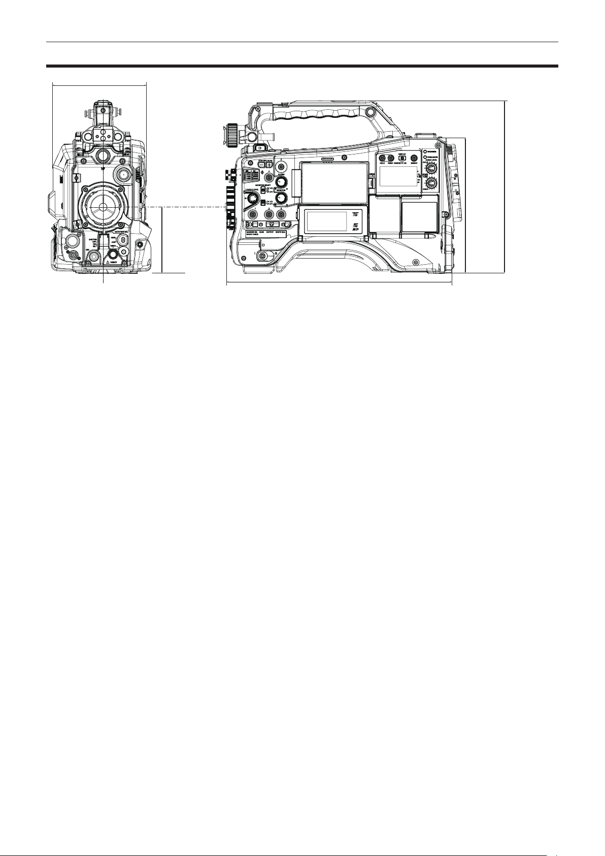
– 235 –
Chapter 11 Specication — Dimensions
Dimensions
143 mm (5-5/8 inches)
267 mm
(10-1/2
inches)
209 mm
(8-7/32
inches)
102 mm (4-1/32
inches)
348 mm (13-23/32 inches)
– 236 –
Chapter 11 Specication — Specications
Specications
General
Power
DC e 12 V (11.0 V – 17.0 V)
Power consumption
32 W (body only, 2160-59.94p/HEVC LongGOP 100M standard recording status, LCD ON)
72 W (with all the accessories connected and maximum power supplied from each output terminal)
indicates safety information.
Operating ambient temperature 0 °C – 40 °C (32 °F – 104 °F)
Operating ambient humidity 10% – 85% (relative humidity)
Storage temperature
−20 °C – 60 °C (−4 °F – 140 °F)
Mass
Approx. 3.4 k] (7.5 lbs.) (body only)
Dimensions (W×H×D)
Body only
143 mm×267 mm×348 mm
(5-5/8 inches × 10-1/2 inches × 13-23/32 inches)
(excluding protrusion)
Camera unit
Pickup device
MOS×1
Number of pixels 11.14 million pixels
Lens mount 2/3-type bayonet
Optical lter f CC lter
A: 3200 K, B: 4300 K, C: 5600 K, D: 6300 K
f ND lter
1: CLEAR, 2: 1/4ND, 3: 1/16ND, 4: 1/64ND
Gain setting
−6 dB to 30 dB: Can be set in 1 dB steps
Digital super gain
(DS.GAIN)
Selectable from 6 dB, 10 dB, 12 dB, 15 dB, 20 dB, 24 dB, 28 dB, 34 dB
Super gain
(S.GAIN)
Selectable from 30 dB, 36 dB, 42 dB
Shutter speed
f When the [SYSTEM] menu → [FREQUENCY] → [59.94Hz] is set
1/100 sec., 1/120 sec., 1/250 sec., 1/500 sec., 1/1000 sec., 1/2000 sec., HALF
f When the [SYSTEM] menu → [FREQUENCY] → [50.00Hz] is set
1/60 sec., 1/120 sec., 1/250 sec., 1/500 sec., 1/1000 sec., 1/2000 sec., HALF
Synchro scan shutter
When the [SCENE FILE] menu → [SYNC SCAN TYPE] → [sec] is set
f When the [SYSTEM] menu → [FREQUENCY] → [59.94Hz] is set
59.94i/59.94p mode: 1/60.0 sec. to 1/7200 sec.
29.97p mode: 1/30.0 sec. to 1/7200 sec.
23.98p mode: 1/24.0 sec. to 1/7200 sec.
f When the [SYSTEM] menu → [FREQUENCY] → [50.00Hz] is set
50i/50p mode: 1/50.0 sec. to 1/7200 sec.
25p mode: 1/25.0 sec. to 1/7200 sec.
Shutter open angle
f When the [SCENE FILE] menu → [SYNC SCAN TYPE] → [deg] is set
3.0 deg – 360.0 deg (can be set in 0.5 deg steps)
Sensitivity
f When the [SYSTEM] menu → [SHOOTING MODE] → [NORMAL] is set
F6 (2000 lx, 3200 K, 89.9% reection, 59.94 Hz)
F7 (2000 lx, 3200 K, 89.9% reection, 50.00 Hz)
f When the [SYSTEM] menu → [SHOOTING MODE] → [HIGH SENS.] is set
F10 (2000 lx, 3200 K, 89.9% reection, 59.94 Hz)
F11 (2000 lx, 3200 K, 89.9% reection, 50.00 Hz)
Minimum subject illumination Approx. 0.005 lx (F1.4, +42 dB (S.GAIN), +34 dB (DS.GAIN))
Image S/N 62 dB (standard)
Horizontal resolution f UHD
2000 TV or higher (center)
f HD
1000 TV or higher (center)
Digital zoom
×2, ×3, ×4
Memory card recorder
Recording media f expressP2 card
f microP2 card
f SDXC memory card
UHS-I/UHS-II, UHS Speed Class 3 compatible, video Speed Class V90 compatible

– 237 –
Chapter 11 Specication — Specications
Recording slot
Card slot dedicated for expressP2×1
microP2/SDXC UHS-II card slot×2
Number of recording pixels
3840×2160 (UHD), 1920×1080 (FHD), 1280×720 (HD)
(AVC-Intra 50: 1440×1080, 960×720)
System frequency 59.94 Hz/50.00 Hz
Recording le format P2 (P2 MXF), MOV (HEVC), MOV (AVC)
Proxy: MOV (AVC)
Recording format f P2
AVC-Intra 422, AVC-LongG50, AVC-LongG25, AVC-LongG12
AVC-Intra 200, AVC-Intra 100, AVC-Intra 50
f Proxy: 4:2:0 (8-bit)
AVC-Proxy G6
f MOV: 4:2:0 (10-bit)
HEVC LongGOP 200M/HEVC LongGOP 150M/HEVC LongGOP 100M
f MOV: 4:2:0 (8-bit)
420LongGOP 150M/420LongGOP 100M
f MOV: 4:2:2 (10-bit)
422LongGOP 150M/422LongGOP 100M/422LongGOP 50M
422ALL-I 400M/422ALL-I 200M/422ALL-I 100M
Recording video signal
3840×2160/59.94p, 50p, 29.97p, 25p, 23.98p
1920×1080/59.94p, 50p, 29.97p, 25p, 23.98p, 59.94i, 50i
1280×720/59.94p, 50p
1440×1080/59.94i, 50i (AVC-Intra 50)
960×720/59.94p, 50p (AVC-Intra 50)
Recording and playback time When using a 64 GB microP2 card
f 1080-59.94p, 50p/AVC-Intra 422
1080-59.94i, 50i/AVC-Intra 200
Approx. 32 minutes
f 1080-59.94i, 50i/AVC-Intra 100
Approx. 1 hour 4 minutes
f 1080-59.94i, 50i/AVC-LongG50
Approx. 2 hours 8 minutes
f 1080-59.94i, 50i/AVC-LongG25
Approx. 4 hours 16 minutes
When using a 64 GB SDXC memory card
f 3840×2160/420LongGOP 150M/59.94p, 50p
Approx. 55 minutes
f 1920×1080/420LongGOP 100M/59.94p, 50p
Approx. 1 hour 20 minutes
f 1920×1080/420LongGOP 50M/29.97p, 25p, 23.98p
Approx. 2 hours 40 minutes
Two-slot function Simultaneous recording, relay recording
Special recording Pre-recording, interval recording, proxy recording
Digital video
Number of quantizing bits f P2:
4:2:2 (10-bit)/4:2:0 (10-bit (AVC-Intra 50))/4:2:0 (8-bit (AVC-LongG12))
f Proxy:
4:2:0 (8-bit (AVC-Proxy G6))
f MOV:
4:2:2 (10-bit)/4:2:0 (8-bit)/4:2:0 (10-bit (HEVC))
Video compression format f P2:
AVC-Intra 422/AVC-LongG50/AVC-LongG25/AVC-LongG12/AVC-Proxy G6 (proxy): MPEG-4 AVC/H.264
High Prole
AVC-Intra 200/AVC-Intra 100/AVC-Intra 50: MPEG-4 AVC/H.264 Intra Prole
f MOV:
H.264/MPEG-4 AVC High Prole, H.265/MPEG-H HEVC Main10 Prole
Digital audio
Recording audio signal f P2:
48 kHz/24 bits, 4ch (excluding AVC-LongG12)
48 kHz/16 bits, 4ch (AVC-Intra 100/AVC-Intra 50/AVC-LongG12)
24 bits/16 bits of AVC-Intra 100/AVC-Intra 50 can be selected by menu
f Proxy:
48 kHz/16-bit, 2ch
f MOV:
48 kHz/24 bit, 4ch

– 238 –
Chapter 11 Specication — Specications
Audio recording format f P2:
LPCM
f Proxy:
AAC
f MOV:
LPCM
Headroom 18 dB/20 dB (Can be selected by menu)
Streaming
Video compression format H.264/MPEG-4 AVC Main Prole
H.264/MPEG-4 AVC High Prole
Video resolution
3840×2160 (UHD), 1920×1080 (FHD), 1280×720 (HD), 640×360, 320×180
Streaming method Unicast, Multicast
Frame rate
f When the [SYSTEM] menu → [FREQUENCY] → [59.94Hz] is set
24 fps, 30 fps, 60 fps
f When the [SYSTEM] menu → [FREQUENCY] → [50.00Hz] is set
25 fps, 50 fps
Bit rate
f When 3840×2160 (UHD)
75 Mbps, 50 Mbps, 25 Mbps, 12 Mbps, 8 Mbps
f Anything other than above
24 Mbps, 20 Mbps, 16 Mbps, 14 Mbps, 8 Mbps, 6 Mbps, 4 Mbps, 3 Mbps, 2 Mbps, 1.5 Mbps, 1 Mbps,
0.7 Mbps, 0.5 Mbps
Audio compression format AAC-LC: 48 kHz/16 bit 2ch
Supported protocol RTSP/RTP/RTMP/RTMPS/SRT
Video output
<SDI OUT1> terminal
f BNC×1
12G-SDI: 0.8 V [p-p], 75 Ω
3G/HD-SDI: 0.8 V [p-p], 75 Ω
f SDI remote control supported
f Output format (4:2:2 (10-bit) output)
3840×2160: 59.94p, 50p, 29.97p, 25p, 23.98p
1920×1080: 59.94p, 50p, 59.94i, 50i, 29.97PsF, 25PsF, 23.98PsF
1280×720: 59.94p, 50p
<SDI OUT2> terminal
f BNC×1
3G/HD-SDI: 0.8 V [p-p], 75 Ω
SD-SDI: 0.8 V [p-p], 75 Ω
f SDI remote control supported
f Output format (4:2:2 (10-bit) output)
1920×1080: 59.94p, 50p, 59.94i, 50i, 29.97PsF, 25PsF, 23.98PsF
1280×720: 59.94p, 50p
720×480: 59.94i
720×576: 50i
<HDMI> terminal
f HDMI type A×1 (not compatible with VIERA Link)
f HDMI remote control supported
f Output format (4:2:2 (10-bit) output)
3840×2160: 59.94p, 50p, 29.97p, 25p, 23.98p
1920×1080: 59.94p, 50p, 59.94i, 50i, 29.97p, 25p, 23.98p
1280×720: 59.94p, 50p
720×480: 59.94p
720×576: 50p
Audio input/output
<AUDIO IN CH1/3> terminal
<AUDIO IN CH2/4> terminal
XLR×2, 3-pin
<LINE>/<MIC>/<MIC+48V> (selected by switch)
f <LINE>:
4 dBu/0 dBu/−3 dBu (selected by menu)
f <MIC>:
−40 dBu/−50 dBu/−60 dBu (selected by menu)
f <MIC+48V>
+ 48 V/OFF compatible
<MIC IN> terminal
XLR×1, 5-pin
+48 V ON/OFF (selected by menu)
−40 dBu/−50 dBu/−60 dBu (selected by menu)
Wireless slot
25-pin, D-SUB, −40 dBu, 2ch supported
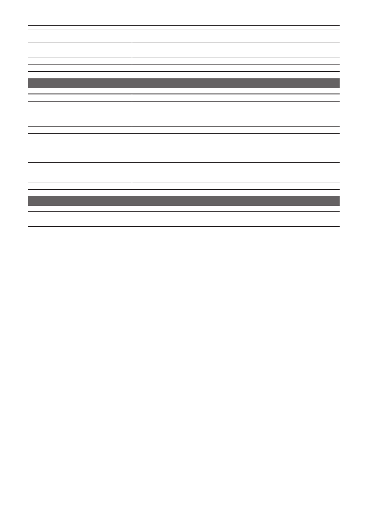
– 239 –
Chapter 11 Specication — Specications
<AUDIO OUT> terminal
XLR×1, 5-pin
4 dBu/0 dBu/−3 dBu (selected by menu), equilibrium low impedance
<SDI OUT> terminal LPCM 4ch
<HDMI> terminal LPCM 2ch
<PHONES> terminal
3.5 mm diameter stereo mini jack×2 (output impedance 100 Ω)
Built-in speaker
20 mm diameter, round×1
Other input/output
<GENLOCK IN> terminal
BNC×1, 1.0 V [p-p], 75 Ω
<TC IN/OUT> terminal
BNC×1
Used as input/output terminal (input/output switch by menu)
f Input: 0.5 V – 8.0 V [p-p], 10 kΩ
f Output: 2.0 V±0.5 V [p-p], low impedance
<DC IN> terminal
XLR×1, 4-pin, DC 12 V (DC 11.0 V – 17.0 V)
<DC OUT> terminal 4-pin, DC 12 V (DC 11.0 V – 17.0 V), maximum output current 1.5 A
<LENS> terminal 12-pin
<VF> terminal 20-pin
<LAN> terminal RJ-45 XLRnet connector: 1000BASE-T/100BASE-TX/10BASE-T
<USB2.0 HOST> terminal Type A connector, 4-pin (5 V, 0.5 A), for attaching the wireless module (optional), for connecting to USB
tethering device
<USB DEVICE> terminal USB 3.1 GEN1 type C connector, with USB mass storage function, without USB bus-powered function
<LIGHT> terminal 2-pin, DC12 V (DC11.0 V – 17.0 V), maximum output current 4.5 A (up to 50 W equivalent)
Monitor
LCD monitor 3.5-inch LCD color monitor: Approx. 2.76 million pixels, touch panel supported
Display window 2.4-inch black and white organic EL
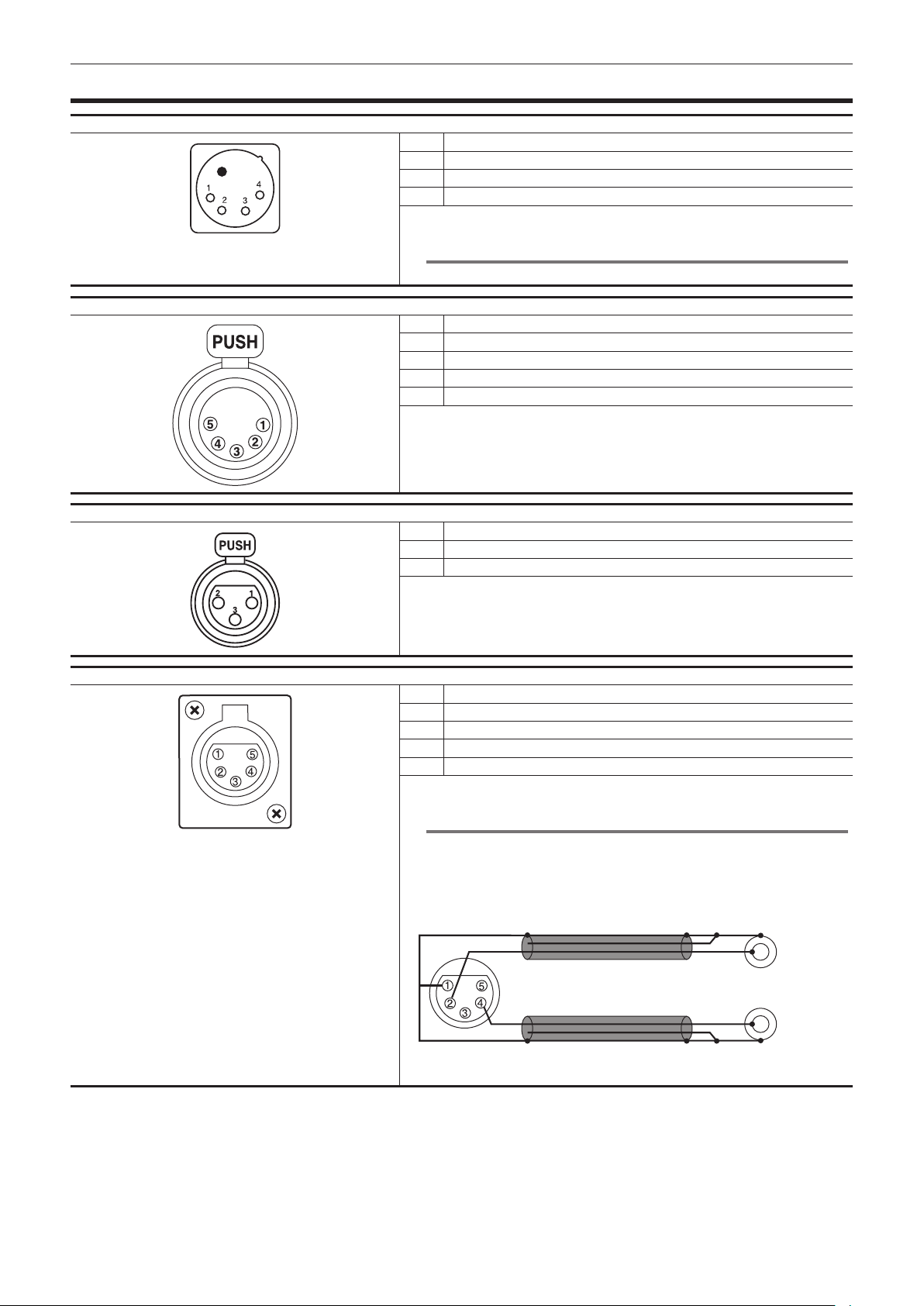
– 240 –
Chapter 11 Specication — Details of the connector signals
Details of the connector signals
DC IN
1 GND
2 NC
3 NC
4
+12 V
Panasonic Parts No.: K1AA104H0038
Manufacturer Parts No.: HA16RX-4P (SW1) (76) (Hirose Electric Co.)
@
NOTE
t Make sure that the polarity of the external power supply is correct.
FRONT MIC IN
1 GND
2 L CH IN(H)
3 L CH IN(C)
4 R CH IN(H)
5 R CH IN(C)
Panasonic Parts No.: K1AB105B0002
Manufacturer Parts No.: NC5FBH (NEUTRIK)
AUDIO IN
1 GND
2 AUDIO IN (H)
3 AUDIO IN (C)
Panasonic Parts No.: K1AY103A0001
Manufacturer Parts No.: HA16PRM-3SG (72) (Hirose Electric Co.)
AUDIO OUT
1 GND
2 L CH OUT(H)
3 L CH OUT(C)
4 R CH OUT(H)
5 R CH OUT(C)
Panasonic Parts No.: K1AA105H0016
Manufacturer Parts No.: HA16RD-5P(76) (Hirose Electric Co.)
@
NOTE
t The <AUDIO OUT> terminal on the camera is the XLR terminal and outputs
balanced audio signals. To make unbalanced connection with an external device
using a pin plug, release pins 3 and 5.
The following is a connection example.
L CH
R CH
Pin terminal
Do not use the cable where the pin 3, pin 5 and pin 1 are connected. Doing so may
result in a malfunction.
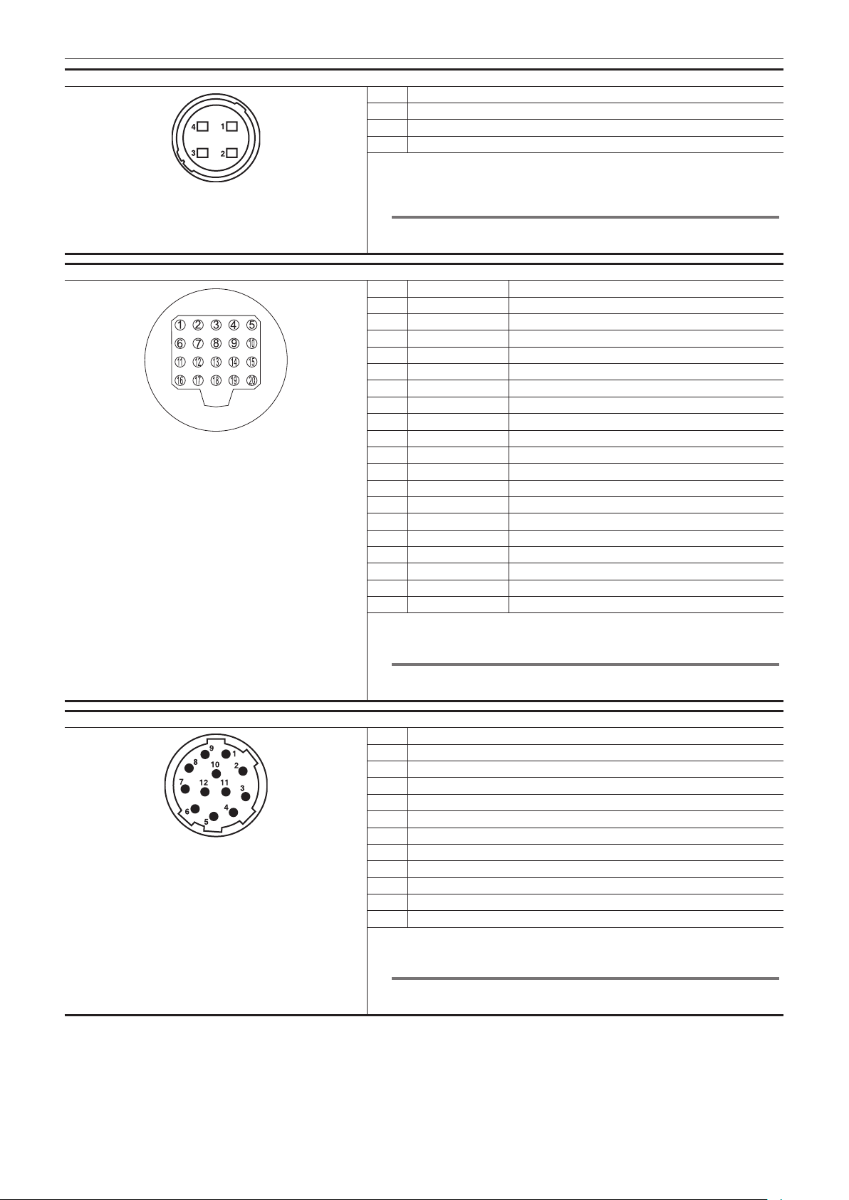
– 241 –
Chapter 11 Specication — Details of the connector signals
DC OUT
1 GND
2 NC
3 NC
4
+12 V OUT DC (11 V – 17 V) (maximum 1.5 A)
Panasonic Parts No.: K1AY104J0001
Manufacturer Parts No.: HR10A-7R-4SC (73) (Hirose Electric Co.)
Cable connector manufacturer Parts No.: HR10A-7P-4(73) (Hirose Electric Co.)
@
NOTE
t Make sure the total of power taken from the <DC OUT> terminal, <VF> terminal,
and <LENS> terminal does not exceed 30 W.
VF
1 UNREG-12V DC 12 V power supply
2 UNREG-12V DC 12 V power supply
3 A9.0V DC 9 V power supply (not used)
4 VF-P
B
-GND Viewnder P
B
signal GND
5 VF-P
R
-GND Viewnder P
R
signal GND
6 VF-Y Viewnder Y signal output
7 VF-Y-GND Viewnder Y signal GND
8 VF-CLK Serial data clock pulse signal
9 VF-WR Pulse signal for loading serial/parallel conversion data
10 VF-DATA Serial data signal for serial/parallel conversion
11 UNREG-GND GND
12 ZEBRA-SW Zebra signal ON/OFF
13 PEAKING Peaking control (not used)
14 SPARE Spare (not used)
15 VF-P
R
Viewnder P
R
signal output
16 VF-P
B
Viewnder P
B
signal output
17 MARKER-SW Marker ON/OFF (not used)
18 FRONT-VR F.AUDIO LEVEL adjustment (not used)
19 VR-GND F.AUDIO LEVEL GND (not used)
20 UNREG-GND GND
Panasonic Parts No.: K1AB120H0001
Manufacturer Parts No.: HR12-14RA-20SC (Hirose Electric Co.)
@
NOTE
t Make sure the total of power taken from the <DC OUT> terminal, <VF> terminal,
and <LENS> terminal does not exceed 30 W.
LENS
1 RET-SW
2 REC-START/STOP
3 GND
4 IRIS-AUTO
5 IRIS-CONT
6
UNREG +12 V (max. 1.5 A)
7 IRIS-POSI
8 IRIS-G-MAX
9 EXT-POSI
10 ZOOM-POSI
11 FOCUS-POSI
12 SPARE
Panasonic Parts No.: K1AY112JA001
Manufacturer Parts No.: HR10A-10R-12SC (71) (Hirose Electric Co.)
@
NOTE
t Make sure the total of power taken from the <DC OUT> terminal, <VF> terminal,
and <LENS> terminal does not exceed 30 W.
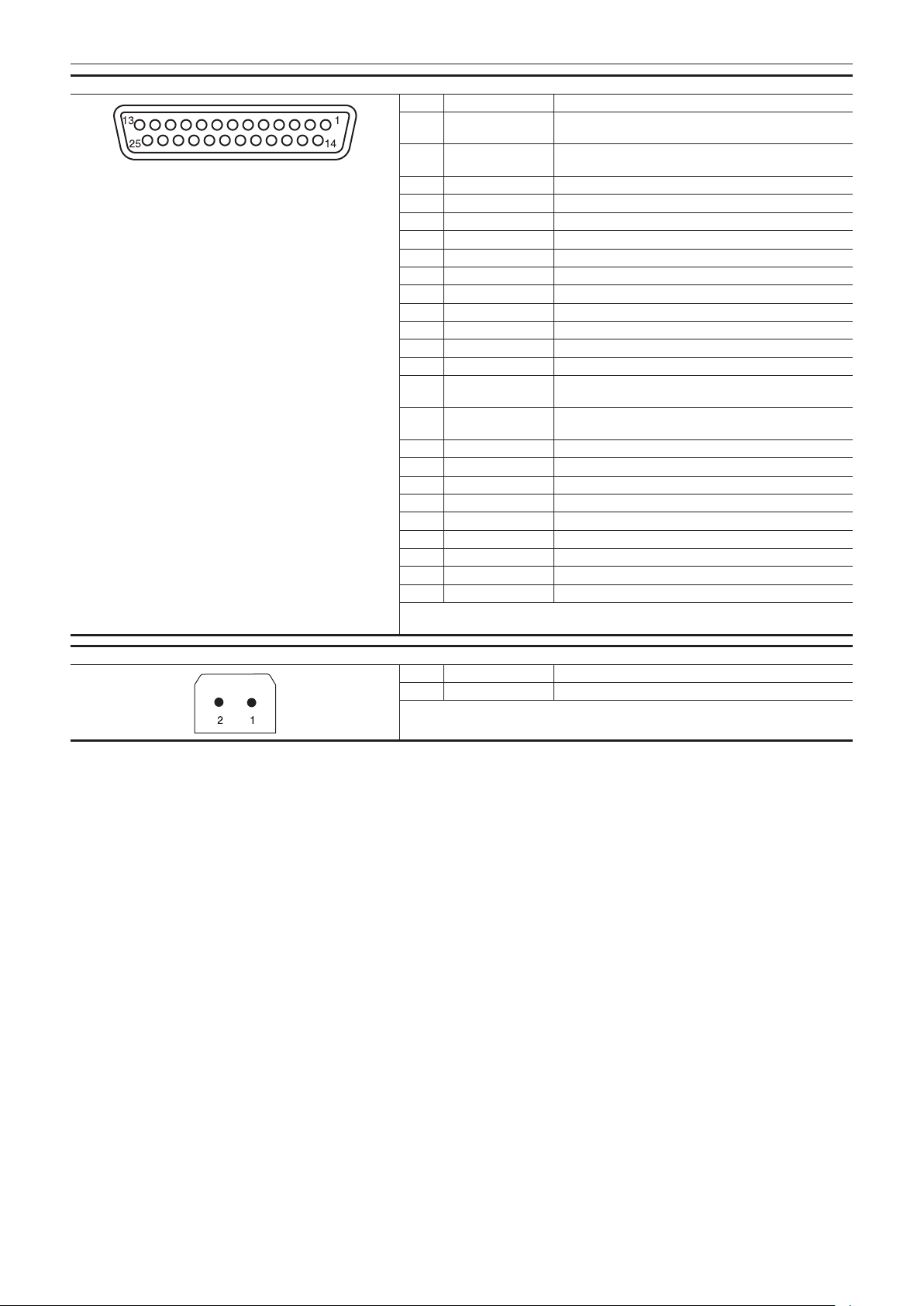
– 242 –
Chapter 11 Specication — Details of the connector signals
Wireless microphone receiver interface
1 CH-1 SHIELD GND
2 CH-1 HOT Audio input from the wireless microphone receiver:
CH1 HOT
3 CH-1 COLD Audio input from the wireless microphone receiver:
CH1 COLD
4 GND GND
5
UNREG +12 V
Power supply to the wireless microphone receiver
6 RX ON Power remote output to the wireless microphone receiver
7 RF WARN RF warning input from the wireless microphone receiver
8 RM5 Not used
9 RM4 Not used
10 SPARE 1 Not used
11 SPARE 2 Not used
12 EXT CLK Not used
13 CLK SHIELD Not used
14 CH-2 SHIELD GND
15 CH-2 HOT Audio input from the wireless microphone receiver:
CH2 HOT
16 CH-2 COLD Audio input from the wireless microphone receiver:
CH2 COLD
17
+5.6 V
Power supply to the wireless microphone receiver
18 VIDEO OUT Not used
19 VIDEO RET Not used
20 VIDEO EN Not used
21 RM 1 (RM CLK) Not used
22 RM 2 (RM DATA) Not used
23 RM 3 (RM WR) Not used
24
RM+5 V
Not used
25 RM GND Not used
Panasonic Parts No.: K1GB25A00010
Manufacturer Parts No.: HDBB-25S (05) (Hirose Electric Co.)
LIGHT
1 12 V UNREG Power supply to the light, etc. (supplied from the battery)
2 GND GND
Panasonic Parts No.: VJS4444

Index
– 243 –
Index
A
Adjusting lens ange back 38
Alert
229
Audio input
138
B
Battery
34
Black balance
131
Built-in battery
46
C
CAC
File
170
Function
39
Card reader mode
196
Chromatic aberration compensation
CAC le
170
Function
39
Clip
Copying
183
Deleting
184
Display
180
Link
186
Operation
179
Playback
187
Protecting
185
Restoring
185
Clip metadata recording function
143
Clock
47
Cloud service
224
Connector signal
240
Counter data
150
CX ROP app
211
D
Date
47
DC power supply
35
Detail display
167
Dimensions
235
Display window
32
E
Electronic shutter
132
Enlarged display
166
expressP2 card
Card access lamp
53
Folder structure
55
Memory card
51
Recording time
54
Use
52
External connection
Card reader mode
196
External equipment
197
External power supply
35
F
FBC function
133
Firmware
233
Flash band compensation function
133
Focus assist function
166
Focus square display
166
G
Genlock
149
H
HDR function
135
High dynamic range function
135
Hot swap recording
143
I
Initialization
Menu
61
Scene les
174
Target items
116
Interval recording
141
L
LCD monitor
168
Lens
37
Adjusting
38
Lens les
175
M
Maker display
165
Memory card
51
Folder structure
55
Recording time
54
Use
52
Menu
Basic operation
59
Conguration
59
Display
61
Initialization
61
Setting
62
Menu items
[AUDIO]
81
[CAMERA]
63
[NETWORK]
101
[OPTION]
112
[OTHERS]
108
[RECORDING]
98
[SCENE FILE]
68
[SYSTEM]
107
[THUMBNAIL]
62
[VIDEO OUT/LCD/VF]
85
Message
230
microP2 card
Card access lamp
53
Folder structure
55
Memory card
51
Recording time
54
Use
52
Microphone
43
Monochrome display
167
MOV format
Folder structure
55
Format
147
Memory card
51
Recording time
54
Volume label
56
N
Network
Connection
202
CX ROP app
211
Preparation
205
Streaming function
215
USB tethering
204
O
Output format
192
P
P2 format
Folder structure
55
Format
147
Memory card
51
Recording time
54
Volume label
56
Peaking display
166
Pre-recording
140
R
Rain cover
45
Recording check function
143
Recording level
138

Index
– 244 –
Recording the proxy data 142
Relay recording
140
Remote function
HDMI remote
198
IP remote
202
SDI remote
198
Resume play
189
S
Scene le
173
Factory setting value
113
Setting data
170
Use
173
Screen display
During playback
159
During shooting
154
Mode check display
161
Thumbnail screen
179
SD card
Card access lamp
53
Folder structure
55
Memory card
51
Recording time
54
Use
52
Setting data
CAC les
39
File structure
170
Lens les
175
Scene le
173
Setup le
171
Setup le
171
User data
170
Shooting
Inspection
48
Procedures
127
Standard recording
128
Shot mark recording function
146
Shoulder strap
44
Simultaneous recording
141
Specications
236
Still image recording function
190
Streaming function
215
Synchro scan mode
132
T
Thumbnail
179
Time code
150
Time data
150
Tripod
44
U
User bits
150
USER button
136
User le
170
W
Warning system
227
Alert
229
Message
230
Warning
227
Waveform monitor function
167
White balance
129
White shading compensation
38
Wireless microphone receiver
43
Wireless module
211
Z
Zebra pattern
165

Web Site: https://www.panasonic.com
©Panasonic Corporation 2019
