Operating Instructions / Owner’s Manual
<Complete Guide>
4K Video Camera
Model No.
HC-X2/HC-X20/
HC-X2GGD/HC-X20GGD
Please read these instructions carefully before using this product, and save this manual for future use.
Register online at http://shop.panasonic.com/support/register
(U.S. customers only)
DVQP2766ZA
F0922GY0

2
About Operating Instructions
This document, “Operating Instructions / Owner’s Manual <Complete Guide>”, includes detailed explanations of all the functions
and operations of the video camera.
Models described in these operating instructions
• This document describes the operation of models HC-X2, HC-X20, HC-X2GGD and HC-X20GGD.
• The illustrations of the products, menu screens, etc., may differ from the actual items. Unless specifically stated otherwise,
screen depictions and illustrations of the unit are of HC-X2.
• The functionalities of the models differ. Be aware that the part numbers for the models that support the functions are shown.
• Not all models may be available depending on the region of purchase.
• Model numbers are abbreviated as follows in these operating instructions:
Conventions used in this manual
• Words and phrases in [ ] brackets indicate content displayed in the LCD monitor.
• Words and phrases in < > brackets indicate design text used on this unit, such as button names.
Reference pages
• Reference pages in this document are indicated by “
Title of reference” or (Î Title of reference: page number).
Terminology
• The battery pack is described as “battery”.
• SDHC memory card, and SDXC memory card are referred to as “SD card” or “memory card” unless distinguished otherwise.
• Images created with one recording operation are referred to as a “clip”.
Model number
Abbreviation used in these operating
instructions
HC-X2/
HC-X2GGD
[X2]
HC-X20/
HC-X20GGD
[X20]

3
Contents
About Operating Instructions 2
Overview 9
Before using the unit ..................................................................................................................................... 10
Description of Parts....................................................................................................................................... 15
Accessories................................................................................................................................................... 23
Optional accessories..................................................................................................................................... 24
When turning on the power for the first time ................................................................................................. 25
[TIME ZONE]...............................................................................................................................................................25
[CLOCK SETTING] .....................................................................................................................................................25
What you can do with this unit ...................................................................................................................... 26
Recording to the memory card....................................................................................................................................26
Linking to external devices..........................................................................................................................................26
Connecting to the network...........................................................................................................................................27
USB tethering connection [X2] ....................................................................................................................................28
Basic operation ............................................................................................................................................. 29
Multidial operation .......................................................................................................................................................29
Touch operation of the LCD monitor ...........................................................................................................................29
Preparations before recording 30
Power supply ................................................................................................................................................ 31
Charging the battery....................................................................................................................................................31
Attaching and removing the battery.............................................................................................................................33
Standard charging time and recordable time ..............................................................................................................33
Connecting to the AC outlet ........................................................................................................................................35
Attaching accessories ................................................................................................................................... 36
Adjusting the grip belt..................................................................................................................................................36
Attaching the lens hood...............................................................................................................................................36
Attaching the eye cup..................................................................................................................................................38
Attaching the external microphone..............................................................................................................................38
Attaching the INPUT terminal cap...............................................................................................................................39
Attaching a tripod ........................................................................................................................................................40
Turning the unit on/off ................................................................................................................................... 41
Charging the built-in battery.......................................................................................................................... 42
Setting the date/time of the internal clock ..................................................................................................... 43
Preparing the memory card .......................................................................................................................... 45
Memory cards supported by the unit (As of August 2022) ..........................................................................................45
Preventing unintentional erasing .................................................................................................................................45
Status of the card access lamp and memory card ......................................................................................................46
Inserting/removing the memory card...........................................................................................................................46
Formatting the memory card .......................................................................................................................................47
Recording time of the memory card.............................................................................................................. 48
Handling the recording data.......................................................................................................................... 50
Folder structure example of a memory card................................................................................................................50
Volume label of the memory card................................................................................................................................51
Folder name of the MOV format/MP4 format video data.............................................................................................51
File name of the MOV format/MP4 format video data .................................................................................................52
About the number of clips that can be recorded to a memory card.............................................................................52
Adjusting and setting the LCD monitor ......................................................................................................... 53
Using the LCD monitor................................................................................................................................................53

Contents
4
Adjusting the LCD monitor ..........................................................................................................................................54
Mirror shooting ............................................................................................................................................................54
Adjusting and setting the viewfinder ............................................................................................................. 55
Using the viewfinder ....................................................................................................................................................55
Adjusting the viewfinder ..............................................................................................................................................56
Tally lamps.................................................................................................................................................... 57
Settings before recording 58
Setting of time data ....................................................................................................................................... 59
Definition of time data..................................................................................................................................................59
User bits settings.........................................................................................................................................................60
Setting the time code...................................................................................................................................................61
Presetting the time code to external [X2] ....................................................................................................................62
Supplying the time code externally [X2] ......................................................................................................................64
Assigning functions to the USER buttons ..................................................................................................... 65
Functions assigned to USER buttons..........................................................................................................................66
Basic operation of the screen 69
Major button operation and screen display ................................................................................................... 70
Major button operation and switching screen ............................................................................................... 71
Operating each screen.................................................................................................................................. 73
Menu 74
Basic operation of the menu ......................................................................................................................... 75
Configuration of the menu ...........................................................................................................................................75
Displaying the menu....................................................................................................................................................76
Operating the menu.....................................................................................................................................................77
Initializing the menu.....................................................................................................................................................78
[THUMBNAIL] menu ..................................................................................................................................... 79
[CAMERA] menu........................................................................................................................................... 80
[SCENE FILE] menu ..................................................................................................................................... 85
[AUDIO] menu............................................................................................................................................... 94
[VIDEO OUT/LCD/VF] menu ........................................................................................................................ 97
[RECORDING] menu .................................................................................................................................. 109
[NETWORK] menu...................................................................................................................................... 112
[SYSTEM] menu ......................................................................................................................................... 120
[OTHERS] menu ......................................................................................................................................... 122
Factory setting value of the scene file......................................................................................................... 126
Target items for scene file/setup file/initialization........................................................................................ 129
[THUMBNAIL] menu..................................................................................................................................................129
[CAMERA] menu.......................................................................................................................................................129
[SCENE FILE] menu .................................................................................................................................................130
[AUDIO] menu...........................................................................................................................................................131
[VIDEO OUT/LCD/VF] menu.....................................................................................................................................131
[RECORDING] menu ................................................................................................................................................133
[NETWORK] menu ....................................................................................................................................................133
[SYSTEM] menu........................................................................................................................................................134
[OTHERS] menu .......................................................................................................................................................135
Handling setting data .................................................................................................................................. 136
Scene files.................................................................................................................................................................136
Setup file ...................................................................................................................................................................139

Contents
5
Shooting 141
Shooting...................................................................................................................................................... 142
About auto mode/manual mode.................................................................................................................. 144
Check videos recorded ............................................................................................................................... 145
Selecting the resolution, codec, and frame rate for recording video........................................................... 146
Adjustable settings when shooting 150
Iris ............................................................................................................................................................... 151
Gain ............................................................................................................................................................ 152
AE level (exposure compensation) ............................................................................................................. 154
Brightness adjustment ................................................................................................................................ 155
Focus .......................................................................................................................................................... 156
Setting the shutter speed ............................................................................................................................ 159
Area mode function..................................................................................................................................... 161
Adjusting the white and black balance 163
White balance adjustment........................................................................................................................... 164
Setting the variable value for the white balance........................................................................................................165
Settings of the auto tracking white balance (ATW) function......................................................................................166
Black balance adjustment ........................................................................................................................... 167
Using the zoom function 168
Adjusting the zoom position ........................................................................................................................ 169
About the zoom speed ..............................................................................................................................................169
Using i.ZOOM............................................................................................................................................................170
Using fast zoom.........................................................................................................................................................170
Image quality adjustment 171
Detail function ............................................................................................................................................. 172
Skin tone function ....................................................................................................................................... 173
RB gain control function.............................................................................................................................. 174
Chroma setting function .............................................................................................................................. 175
Matrix function............................................................................................................................................. 176
Color correction function ............................................................................................................................. 177
Black control function.................................................................................................................................. 178
Gamma function.......................................................................................................................................... 179
Knee function .............................................................................................................................................. 180
White clip function....................................................................................................................................... 181
Audio input 182
Switching the audio input ............................................................................................................................ 183
Using the built-in microphone....................................................................................................................................184
Using audio equipment/external microphone (XLR, 3-pin)........................................................................................184
Adjusting the audio recording level ............................................................................................................. 185
Monitoring the audio ................................................................................................................................... 187
Special recording function 188
Variable frame rate (VFR) recording function/super slow recording function ............................................. 189

Contents
6
Variable frame rate (VFR) .........................................................................................................................................189
Super slow recording function...................................................................................................................................191
High dynamic range (HDR) recording function [X2].................................................................................... 193
V-Log recording function [X2] ..................................................................................................................... 194
Pre-recording .............................................................................................................................................. 195
Relay recording........................................................................................................................................... 196
Simultaneous recording .............................................................................................................................. 197
Background recording................................................................................................................................. 198
Dual codec recording [X2]........................................................................................................................... 200
Interval recording ........................................................................................................................................ 202
IR recording ................................................................................................................................................ 203
Convenient shooting functions 204
Zebra patterns display ................................................................................................................................ 205
Displaying the marker ................................................................................................................................. 206
Focus assist function .................................................................................................................................. 208
Face detection/tracking AE&AF function .................................................................................................... 211
Optical image stabilizer function ................................................................................................................. 213
Dynamic range stretcher function ............................................................................................................... 214
Time stamp function.................................................................................................................................... 215
Waveform monitor function ......................................................................................................................... 216
Digital zoom function................................................................................................................................... 217
Level gauge ................................................................................................................................................ 218
Flash band compensation (FBC) function................................................................................................... 219
Operation icon screen display..................................................................................................................... 220
Multi manual function .................................................................................................................................. 221
Displaying the operation icon screen ........................................................................................................................222
Adjusting headphone volume....................................................................................................................................222
Playback 223
Thumbnail operation ................................................................................................................................... 224
Thumbnail operation overview ..................................................................................................................................224
Thumbnail screen......................................................................................................................................................225
Playing back clips ....................................................................................................................................... 229
Useful playback function ............................................................................................................................. 232
Copying clip ................................................................................................................................................ 233
Deleting clips............................................................................................................................................... 234
Protecting clips............................................................................................................................................ 235
Restoring clips ............................................................................................................................................ 236
Still image recording function...................................................................................................................... 237
Output format 238
Format that can be output from the SDI OUT terminal [X2]........................................................................ 239
Format that can be output from the HDMI terminal..................................................................................... 240
Note regarding simultaneous output to the SDI OUT terminal and the HDMI terminal [X2] ....................... 242
Screen status display 244
Screen display during shooting................................................................................................................... 245

Contents
7
Screen display during playback .................................................................................................................. 253
Checking and displaying shooting status.................................................................................................... 254
Mode check display .................................................................................................................................... 256
Connecting to External Devices 260
Connecting with headphones and TV/monitor ............................................................................................ 261
Headphones ..............................................................................................................................................................261
Remote control ..........................................................................................................................................................261
TV/monitor.................................................................................................................................................................262
Connection function via the USB terminal .................................................................................................. 263
Connection with a computer in card reader mode.....................................................................................................263
Operating environment (mass storage).....................................................................................................................265
Remote operation by iPhone/iPad or Android terminal............................................................................... 266
Network Connection 267
Network connection .................................................................................................................................... 268
Available functions ....................................................................................................................................................269
About the wireless LAN function on this unit.............................................................................................................269
Preparing for connection ...........................................................................................................................................270
Network settings ......................................................................................................................................... 271
Wireless LAN settings ...............................................................................................................................................271
Wired LAN settings....................................................................................................................................................274
USB tethering setting [X2] .........................................................................................................................................276
Confirming the network status...................................................................................................................................276
Confirming the network environment.........................................................................................................................277
Connecting to the iPhone/iPad or Android terminal .................................................................................... 278
Unit settings...............................................................................................................................................................278
Preparing the HC ROP app.......................................................................................................................................279
Connecting to the HC ROP app ................................................................................................................................279
Operation while the HC ROP app is connected ........................................................................................................279
Streaming function ...................................................................................................................................... 280
Basic setting of the camera .......................................................................................................................................281
Setting for each protocol and starting the streaming.................................................................................................283
Management of setting information ...........................................................................................................................285
Entering the setting using the setting tool .................................................................................................................286
Notes 287
Frequently asked questions ........................................................................................................................ 288
Power supply/Battery ................................................................................................................................................288
Memory card .............................................................................................................................................................289
Indication ...................................................................................................................................................................289
Shooting ....................................................................................................................................................................289
Playback....................................................................................................................................................................290
Connections with external devices............................................................................................................................290
Computers.................................................................................................................................................................290
Others........................................................................................................................................................................291
Warning system .......................................................................................................................................... 292
Recording function that cannot be used simultaneously............................................................................. 297
Updating the unit’s firmware ....................................................................................................................... 298
Cleaning and storing ................................................................................................................................... 299
Trademark................................................................................................................................................... 300

Contents
8
Specification 302
Dimensions ................................................................................................................................................. 303
Specifications.............................................................................................................................................. 304
General......................................................................................................................................................................304
Camera......................................................................................................................................................................305
Memory card recorder...............................................................................................................................................307
Digital video...............................................................................................................................................................308
Digital audio...............................................................................................................................................................309
Dual codec [X2].........................................................................................................................................................309
Streaming..................................................................................................................................................................309
Wi-Fi..........................................................................................................................................................................310
Video output ..............................................................................................................................................................310
Audio input ................................................................................................................................................................311
Audio output ..............................................................................................................................................................311
Other input/output......................................................................................................................................................311
Monitor ......................................................................................................................................................................312
AC adaptor ................................................................................................................................................................312
Battery charger..........................................................................................................................................................312
Battery pack (AG-VBR59) .........................................................................................................................................313


Overview – Before using the unit
10
Before using the unit
Before using the unit, always check if the built-in battery is not consumed, and then
set the date/time.
The date of the internal clock of the unit resets to January 1, 2022 if the built-in battery is exhausted. This may result in the meta
data of the clip not being recorded correctly, and it may not display correctly in the thumbnail screen.
Connect the AC adaptor to the main unit or attach a battery when recharging the built-in battery.
The date/time set on the main unit is maintained for approximately 4 months when left in this state for approximately 24 hours.
(Recharged even when the power is on.)
• For details about setting the time zone and date/time (
Î[TIME ZONE]: 25, [CLOCK SETTING]: 25).
Do not use the unit in oily-smoky or dusty places.
Performance may be adversely affected if small particles or other foreign objects get inside the product.
Take extra care in environments where a special effect such as theatrical smoke is used.
When using this product during rain or snow or when at the beach, be careful that
water does not get inside the camera.
Water causes damage to the camera and memory card. (Repair may be impossible)
Take care so sand and/or dust do not get inside the camera when using it at the beach,
etc.
Sand and dust may damage the camera and memory card. (Be careful when inserting or removing the memory card)
AC adaptor, battery charger, and battery
• It may take more time to charge or may not be able to charge when the temperature of the battery is extremely high or
extremely low.
• When the charging lamp continues to flash in orange, check if there is any debris, foreign object, or dirt attached to the
terminal section of the battery or the battery charger, and reconnect it correctly. Always disconnect the power plug from the
power outlet before removing the debris, foreign object, or dirt attached to the terminal section.
• The charging lamp will flash in orange when the temperature of the battery is extremely high or low.
Then, charging will start automatically after the battery reaches chargeable temperature.
• If the charging lamp continues to flash in orange even when the battery is at its optimal temperature, the battery or battery
charger may be damaged. Consult the dealer.
• Noise may be generated in radio when the unit is used close to a radio (especially when receiving AM). Keep a distance of
1 m (approx. 3.3 feet) or more when using.
• Oscillating sound may generate inside the AC adaptor or the battery charger during the use, but this is not a malfunction.
• Always disconnect the power plug from the power outlet after the use. (Power of approximately 0.1 W is consumed by the AC
power itself if kept connected)
• Do not get the terminal section of the AC adaptor, the battery charger, or the battery dirty. Install the device close to the power
outlet so the disconnection device (power plug) can be easily reached.
Memory cards
• The surface of this unit or the memory card may get slightly hot when used for a long period of time, but this is not a
malfunction.
• The amount of memory included on the label of the memory card is the total amount of memory below.
– Capacity to protect and manage copyright
– Capacity usable as the normal memory on the unit or a PC.
• Do not give a strong impact to, bend, or drop the memory card.
• Memory card data may become destroyed or erased in the following cases.
– Electrical noise or static electricity
– Malfunction of the unit or the memory card
• Do not perform the following operations when accessing the memory card (the card 1 access lamp/card 2 access lamp is
flashing in orange).
– Removing the memory card
– Disconnecting battery or the AC adaptor without turning off the main unit
– Apply vibration of impact

Overview – Before using the unit
11
Take care not to drop the main unit when carrying the camera.
• Strong impact will damage the main unit, and it may not operate properly.
• Hold the handle or grip when carrying the camera, and handle it carefully.
Do not apply insecticide or volatile material to the camera.
• The main unit may deform or the paint may peel off when insecticide or volatile material is applied.
Do not allow the camera to remain in contact with a rubber or vinyl object for a long
period of time.
Disconnect the battery or disconnect the AC cable from the power outlet after the use.
Battery characteristics
The battery is a rechargeable lithium-ion battery. It produces electrical energy via an internal chemical reaction. This chemical
reaction is effected by the ambient temperature and humidity. The usable time of the battery becomes shorter when the
temperature gets higher or lower. When used in an environment with extremely low temperature, it can only be used for
approximately 5 minutes.
When the battery is in an extremely hot environment, its protective function will operate and the unit cannot be used temporarily.
After using the unit, be sure to remove the battery.
Securely remove the battery from the camera.
(Minute current is consumed even if the camera is turned off when the battery is left attached)
The battery will become over discharge and may become unusable even if it is recharged when the battery is left attached for
long period of time.
Do not remove the battery when the power is turned on.
Turn off the power and remove the battery after the operation lamp goes completely out.
Take proper care of the battery terminal.
Do not allow dust or foreign objects on the battery terminal.
Confirm that the battery and its terminal section is not deformed when the battery is dropped by mistake.
Do not mount the deformed battery into a camera or mount to the battery charger. This may damage the camera or the battery
charger.
Cautions when throwing memory cards away or transferring them to others
Formatting memory cards or deleting data using the functions of the unit or a computer will merely change the file management
information: it will not completely erase the data on the cards.
It is recommended to completely erase the data in following method when discarding/conveying.
• Physically destroy the memory card itself
• Completely erase the data in the memory card using a commercially available data erasing software for PC, etc.
Users are responsible for managing the data stored in their memory card.
LCD monitor and viewfinder
• Condensation sometimes forms on the LCD panel of the LCD monitor in locations subject to extreme temperature differences.
If this happens, wipe with a soft, dry cloth.
• Do not touch the LCD monitor with your finger nails, or rub or press with strong force.
• The LCD monitor will be slightly darker than normal immediately after the power is turned on when the camera is very cold. It
will return to its regular brightness when the internal temperature increases.
• The LCD monitor and viewfinder are managed with high precision so that at least 99.99 % of the dots are effective pixels and
0.01 % or less are invalid pixels and always lit. This is not a malfunction and it has no effect whatsoever on the recorded
images.
• The viewfinder for this camera uses an organic EL display. The image may burn into the screen if the same image or letters
are left displayed on the screen for a long time. There is no problem with the recorded images.
Switch the screen by turning off the screen or by using the eye sensor, etc.
• It may become difficult to see or difficult to recognize the touch when a LCD protection sheet is affixed.

Overview – Before using the unit
12
About Condensation (When the lens, the viewfinder or LCD Monitor is fogged up)
Condensation occurs when there is a change in temperature or humidity, such as when the unit is taken from outside or a cold
room to a warm room. Please be careful, as it may cause the lens, the viewfinder or LCD monitor to become soiled, moldy, or
damaged.
When taking the unit to a place which has a different temperature, if the unit is accustomed to the room temperature of the
destination for about 1 hour, condensation can be prevented. (When the difference in temperature is severe, place the unit in a
plastic bag or the like, remove air from the bag, and seal the bag.)
When condensation has occurred, remove the battery and/or the AC adaptor and leave the unit like that for about 1 hour. When
the unit becomes accustomed to the surrounding temperature, fogginess will disappear naturally.
Caution regarding laser beams
The MOS sensor may be damaged if the MOS sensor is subjected to light from a laser beam.
Take sufficient care to prevent laser beams from striking the lens when shooting in an environment where laser devices are
used.
Treatment of clips
Clips recorded with devices other than this unit are not supported by this unit.
Regarding system frequencies
You can change the system frequency (59.94 Hz/50.00 Hz) for this unit by using the menu. (
Î[FREQUENCY]: 120)
• When AVCHD clips are recorded, it is not possible to use the same memory card with different system frequencies. When the
system frequency is changed, use a different memory card.
Note the following points.
• If you prepare to record important images, always shoot some advance test footage to verify that both pictures and sound are
being recorded normally.
• Panasonic will not assume liability when video or audio recording fails due to a malfunction of the unit or the memory card
during the use.
• Set the calendar (datetime of the internal clock) and the time zone, or check the setting before recording. This will have an
effect on the management of the recorded contents.
Exemption of liability
Panasonic is not liable in any way regarding following.
1 Incidental, special, or consequential damages caused directly or indirectly by the unit
2 Damages, breakage of the unit, etc., caused by misuse or carelessness of the customer
3 When disassembly, repair, or modification (including the software) of the unit is performed by the customer
4 Inconveniences, damnification, or damages by not being able to record and/or display the video due to any reasons
including failure or malfunction of the unit and recording media
5 Inconveniences, damnification, or damages resulting from malfunction of the system combining with any third party
equipment
6 A liability claim or any claim for a privacy violation by an individual or a group that was the subject of the video that the
customer has shot (including recording) that became public by any reason (including using with the network user
authentication turned OFF)
7 The registered information is lost due to any reason (including initializing this unit because the authentication information
such as user name or password is forgotten)
Be careful with regard to copyrights
Under copyright law, you may not use the images and audio you have recorded for other than personal enjoyment without the
permission of the copyright holder.

Overview – Before using the unit
13
Cautions regarding network
Since this unit is used connected to a network, following mischief may occur.
1 Leaking or divulging of information through the unit
2 Fraudulent operation of the unit by a malicious third party
3 Obstruction and/or stopping of the unit by a malicious third party
It is customer’s responsibility to take sufficient network security measures including the following to prevent damage caused by
such mischief. Please note that Panasonic is not liable in any way for damage caused by such mischief.
• Use the unit on a network where safety is secured by using a firewall, etc.
• When using the unit on a system where a computer, tablet, smartphone, or other device is connected, make sure that
checking and cleaning of infection by computer virus and malicious program is performed periodically.
• In order to prevent malicious attacks, use text strings that have 8 characters or more including 3 or more character types for
the authentication information (such as user name and password) so that a third party cannot guess your authentication
information.
• Set and store the authentication information (user name, password, etc.) appropriately so it is not visible to the third party.
• Periodically change the authentication information (user name, password, etc.) and do not use the same authentication
information as other accounts.
• To prevent the setting information in the unit to leak to the network, execute measure such as restricting the access with user
authentication, etc.
• Do not install in a location where the unit, cable, etc., can be easily damaged.
Security
Take caution in handling the unit or memory card so it is not stolen, lost or neglected, and handle with care when discarding or
providing. Note that Panasonic is not liable to leakage, falsification, or loss of information caused by them.
When requesting repairs, or when transferring ownership/disposing of the product
• After first taking note of personal information, make sure you delete information in this unit that includes personal information,
including the wireless LAN connection settings, etc., that you have registered or set in this unit, using the following menu
settings:
– [NETWORK] menu
¨ [UTILITY] ¨ [NETWORK INITIALIZE]
– [OTHERS] menu ¨ [MENU INITIALIZE]
• Remove the Memory Card from this unit when requesting a repair.
• Settings may return to factory default when this unit is repaired.
• Please contact the dealer where you purchased this unit or Panasonic if above operations are not possible due to malfunction.
Cautions for use
Keep this unit as far away as possible from electromagnetic equipment (such as microwave ovens, TVs, video games
etc.).
• If you use this unit on top of or near a TV, the pictures and/or sound on this unit may be disrupted by electromagnetic wave
radiation.
• Do not use this unit near cell phones because doing so may result in noise adversely affecting the pictures and/or sound.
• Recorded data may be damaged, or pictures may be distorted, by strong magnetic fields created by speakers or large motors.
• Electromagnetic wave radiation generated by microprocessors may adversely affect this unit, disturbing the pictures and/or
sound.
• If this unit is adversely affected by electromagnetic equipment and stops functioning properly, turn this unit off and remove the
battery or disconnect AC adaptor. Then reinsert the battery or reconnect AC adaptor and turn this unit on.
Do not use this unit near radio transmitters or high-voltage lines.
If you record near radio transmitters or high-voltage lines, the recorded pictures and/or sound may be adversely affected.
When this unit is turned on, do not use it in direct contact with the skin for a long period of time.
• When using this unit for a long period of time, use a support such as a tripod. Low temperature burns may result if any high
temperature part of this unit or hot air from the ventilation openings on the front side of the hand strap of this unit is in direct
contact with the skin for a long period of time.
Caution regarding the lens and the viewfinder
• Do not aim the lens or the viewfinder at the sun or strong light. Doing so may cause the unit to malfunction.

Overview – Before using the unit
14
About using a headphone
• Excessive sound pressure from earphones and headphones can cause hearing loss.
• Listening at full volume for long periods may damage the user’s ears.
Overview – Description of Parts
15
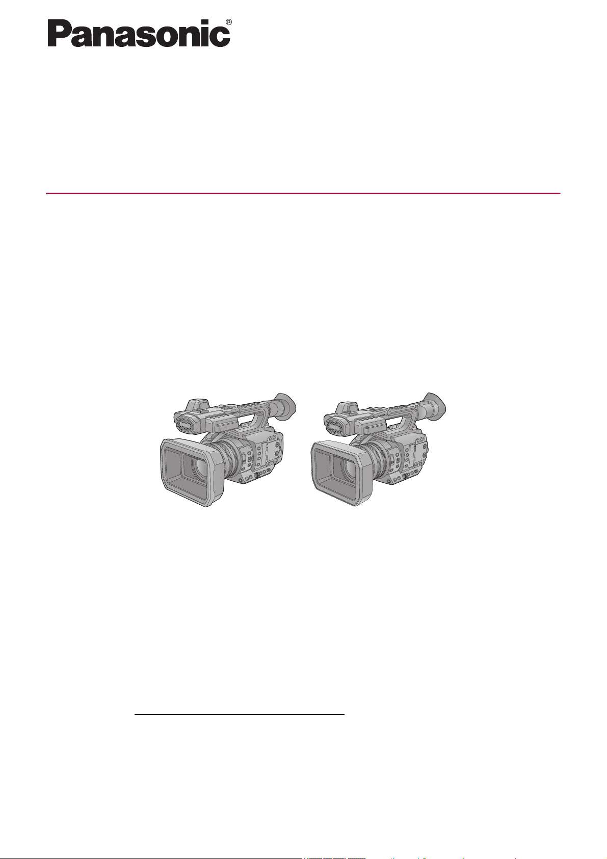
Description of Parts
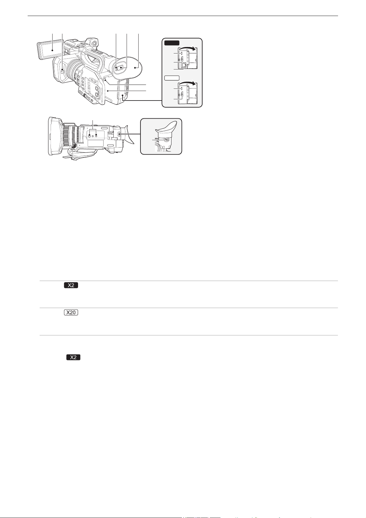
(1) Lens hood (ÎAttaching the lens hood: 36)
(2) Focus ring (
ÎFocusing (manual focus): 156)
When manual focus mode is on, you can focus manually.
(3) Zoom ring (
ÎAdjusting the zoom position: 169)
Manually adjusts the zoom lens.
(4) Iris ring (
ÎIris: 151)
When manual iris mode is on, you can adjust the lens stop manually.
(5) <O.I.S.>/<USER6> button (
ÎAssigning functions to the USER buttons: 65, Optical image stabilizer function:
213
)
Switches enable/disable of the optical image stabilizer function.
This is also used as the USER button (USER6).
(6) <D.ZOOM>/<USER7> button (
ÎAssigning functions to the USER buttons: 65, Digital zoom function: 217)
Switches enable/disable of digital zoom.
This is also used as the USER button (USER7).
(7) <WFM>/<USER4> button (
ÎAssigning functions to the USER buttons: 65, Waveform monitor function: 216)
Switches the display of the waveform monitor.
This is also used as the USER button (USER4).
(8) <ZEBRA>/<USER5> button (
ÎAssigning functions to the USER buttons: 65, Zebra patterns display: 205)
Switches display/hide of zebra patterns.
This is also used as the USER button (USER5).
(9) <FOCUS ASSIST> button (
ÎFocus assist function: 208)
Switches enable/disable of the focus assist function.
(10) <USER1> button (
ÎAssigning functions to the USER buttons: 65, Area mode function: 161)
Used as a USER button (USER1).
• [AREA] is allocated at the time of purchase. Assigns the area function.
(11) <USER2> button (
ÎAssigning functions to the USER buttons: 65, AE level (exposure compensation): 154)
Used as a USER button (USER2).
• [AE LEVEL] is allocated at the time of purchase. Switches enable/disable of the AE level function.
Set the target value of the AE level in the [SCENE FILE] menu
¨ [AE LEVEL EFFECT].
(12) <USER3> button (
ÎAssigning functions to the USER buttons: 65)
Used as a USER button (USER3).
• [SLOT SEL] is allocated at the time of purchase. Selects the card slot to record to or play back from.
(1)
(2)
(3)
(4)
(11)
(12)
(16)
(10)
(9)
(13)
(14)
(17)
(15)
(8)
(7)
(5) (6)
(19)(18) (20) (21) (22) (23)

Overview – Description of Parts
16
(13) <WHITE BAL> button (ÎAdjusting the white and black balance: 163)
Selects the method for adjustment of the white balance. Each time you press the button, the white balance switches in the
order “Preset”, “Ach”, “Bch”.
“Preset”:
Adjusts the white balance to the preset value. Each time you either press the USER button assigned to [AWB] or touch the
USER button icon, the setting changes in the order [P 3200K], [P 5600K], “VAR” (screen display example: [V 3200K]).
“Ach”/“Bch”:
Selects when using the stored value for the adjustment of the white balance.
(14) <PUSH AUTO> button (ÎAuto focusing: 157)
When in the manual focus mode, focus is made automatic while the <PUSH AUTO> button is being pressed.
(15) <ND FILTER> switch (
ÎBrightness adjustment: 155)
Selects the ND filter to suit the illumination of the subject.
<1/64>:
Reduces the amount of light entering the MOS sensor to 1/64.
<1/16>:
Reduces the amount of light entering the MOS sensor to 1/16.
<1/4>:
Reduces the amount of light entering the MOS sensor to 1/4.
<CLR>:
Does not use the ND filter.
(16) <FOCUS A/M/¶> switch (ÎFocusing (manual focus): 156)
Select the focus function.
<A>:
Changes to the auto focus mode. The auto focus mode adjusts the focus automatically.
<M>:
Changes to the manual focus mode. Control the focus ring manually to adjust the focus.
<¶>:
If you move the <FOCUS A/M/¶> switch towards <¶>, focus will be adjusted to MF95 on the infinity side. (The <FOCUS
A/M/¶> switch will return to the <M> position.)
(17) <IRIS> button (ÎIris: 151)
Selects the method for adjustment of the lens stop.
(18) <GAIN> button (ÎGain: 152)
Selects the method for adjusting screen brightness.
(19) <SHUTTER> button (
ÎSetting the shutter speed: 159)
Switches the shutter mode.
(20) Multidial (
ÎMulti manual function: 221)
Moves, selects, and sets the menu while the menu is displayed.
Use the multidial to also operate thumbnails, select the multi manual function and select/set the various operation icons.
(21) <EXIT> button
Returns to one level higher when the menu is displayed. Pressing the <EXIT> button without confirming the setting value
will not reflect the change in the setting.
(22) <MENU> button (
ÎBasic operation of the menu: 75)
Displays the menu. Pressing the <MENU> button while the menu is displayed closes the menu.
Press the button while the thumbnail screen is displayed to display the operation screen of the thumbnail menu, and clips
can be deleted.
(23) <AUTO/MANU> switch (
ÎAbout auto mode/manual mode: 144)
Selects the method to adjust the focus, gain, iris, white balance, and shutter speed at shooting.
<AUTO>:
Adjusts automatically. (Auto mode)
<MANU>:
Adjusts manually. (Manual mode)
Overview – Description of Parts
17
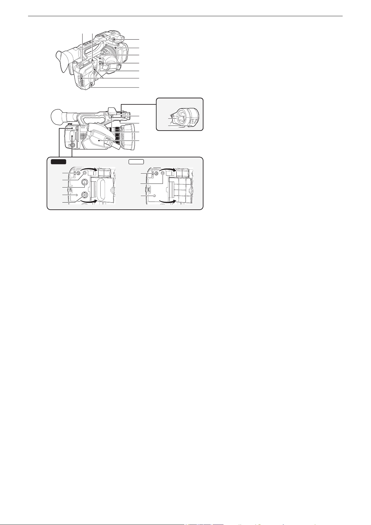
(24) Handle
(25) Built-in microphone (
ÎUsing the built-in microphone: 184)
This is the built-in stereo microphone <L>/<R>.
(26) Front tally lamp (
ÎTa ll y l am ps : 5 7)
Illuminates when the recording is started. Flashes when the battery level becomes low.
Whether or not to illuminate the lamp can be set in the menu.
(27) Lens cover (
ÎOpening and closing the lens cover: 37)
(28) Card 1 access lamp (
ÎStatus of the card access lamp and memory card: 46)
Indicates the access status for recording and playback of the memory card inserted in card slot 1.
Whether or not to illuminate the lamp can be set in the menu.
(29) Card slot 1 (
ÎInserting/removing the memory card: 46)
A slot for the memory card.
(30) Card 2 access lamp (
ÎStatus of the card access lamp and memory card: 46)
Indicates the access status for recording and playback of the memory card inserted in card slot 2.
Whether or not to illuminate the lamp can be set in the menu.
(31) Card slot 2 (
ÎInserting/removing the memory card: 46)
A slot for the memory card.
(32) Fan outlet
Fan outlet for cooling fan. Do not block this while the unit is being used.
(33) Lens
(34) <AWB>/<USER9> button (
ÎAssigning functions to the USER buttons: 65, Adjusting the white and black
balance: 163
)
Adjusts the white balance or black balance.
This is also used as the USER button (USER9).
(35) <INPUT1> switch (
ÎUsing audio equipment/external microphone (XLR, 3-pin): 184)
Switches audio input signals connected to the <AUDIO INPUT1> terminal.
<LINE>:
Select when audio equipment is connected by the line input.
<MIC>:
Select when the external microphone is connected.
<i48V>:
Select when the external microphone is connected and the microphone needs a power supply.
(27)
(26)
(25)
(24)
(33)
(34)
(32)
(29)
(28)
(31)
(30)
(40)(39)(38)
(37)(36)(35)

Overview – Description of Parts
18
(36) CH1 SELECT switch (ÎAudio input: 182)
Selects the audio to be recorded on audio channel 1.
<INT(L)>:
Audio from the built-in microphone L (left) ch is recorded to audio channel 1.
<INPUT1>:
Records input signals from the <AUDIO INPUT1> terminal.
<INPUT2>:
Records input signals from the <AUDIO INPUT2> terminal.
(37) <AUDIO LEVEL CH1> dial (ÎAdjusting the audio recording level: 185)
Adjust the recording level of audio channel 1.
(38) <INPUT2> switch (
ÎUsing audio equipment/external microphone (XLR, 3-pin): 184)
Switches audio input signals connected to the <AUDIO INPUT2> terminal.
<LINE>:
Select when audio equipment is connected by the line input.
<MIC>:
Select when the external microphone is connected.
<i48V>:
Select when the external microphone is connected and the microphone needs a power supply.
(39) CH2 SELECT switch (ÎAudio input: 182)
Selects the audio to be recorded on audio channel 2.
<INT(R)>:
Audio from the built-in microphone R (right) ch is recorded to audio channel 2.
<INPUT1>:
Records input signals from the <AUDIO INPUT1> terminal.
<INPUT2>:
Records input signals from the <AUDIO INPUT2> terminal.
(40) <AUDIO LEVEL CH2> dial (ÎAdjusting the audio recording level: 185)
Adjust the recording level of audio channel 2.
Overview – Description of Parts
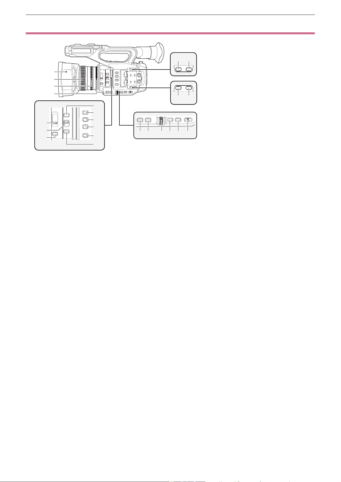
19
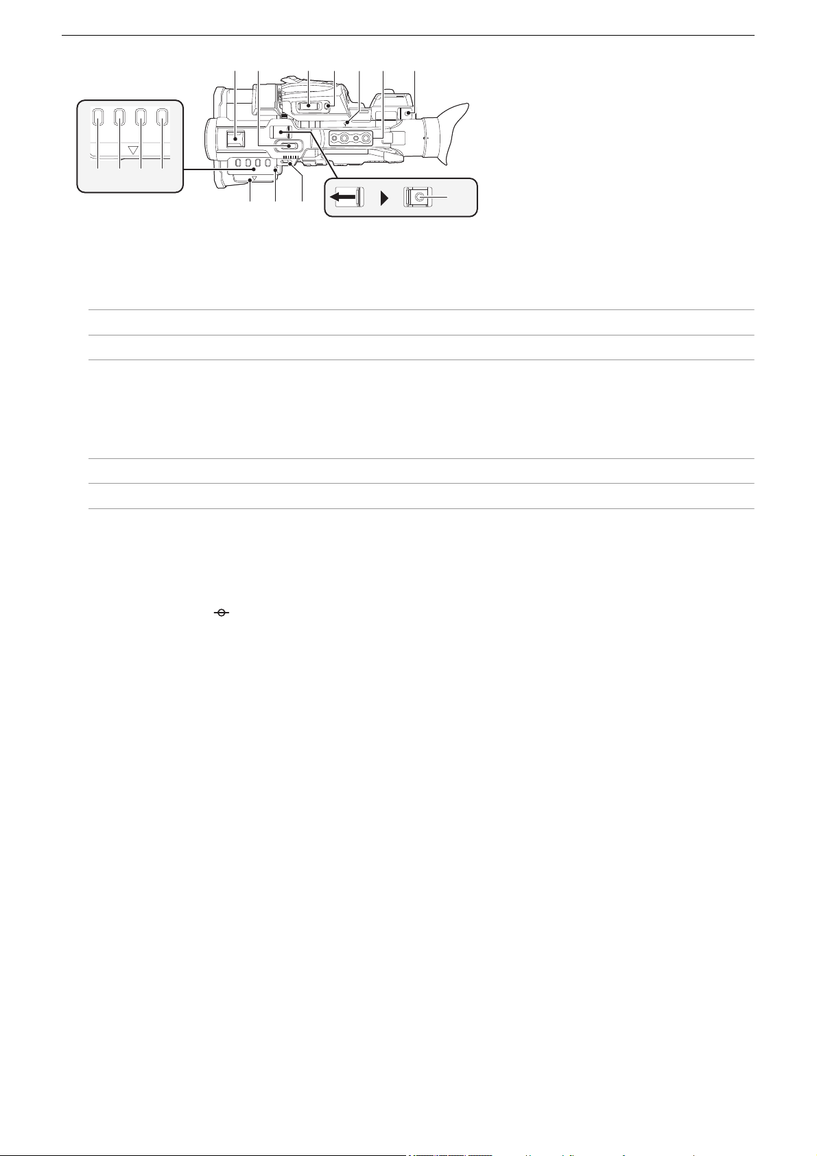
(41) LCD monitor (ÎUsing the LCD monitor: 53)
(42) Lens cover opening and closing lever (
ÎOpening and closing the lens cover: 37)
Opens/closes the lens cover.
(43) Eye sensor
Screen is displayed on the viewfinder when an eye is brought close.
(44) Viewfinder (
ÎUsing the viewfinder: 55)
(45) Eye cup (ÎAttaching the eye cup: 38)
(46) Battery release button (
ÎAttaching and removing the battery: 33)
Used when removing the battery from the main unit.
(47) Battery mounting section (
ÎAttaching and removing the battery: 33)
Attaches a battery.
(48) USB terminal (ÎConnection function via the USB terminal: 263, Network connection: 268)
Connect to a computer with the USB cable to transfer data.
(For the )
When connecting the camera to iPhone/iPad or Android device using USB cable, connection to the network is possible
using USB tethering.
(For the )
When the unit and a USB ethernet adaptor (commercially available) are connected, connection to the network is possible
via a LAN terminal.
(49) <HDMI> terminal (ÎTV/monitor: 262)
A terminal to output video signal by connecting a monitor, etc.
(50) (For the )
<LAN> terminal (
ÎPreparing for connection: 270)
Connects the LAN cable.
(51) Tripod mounting holes (
ÎAttaching a tripod: 40)
Attach the tripod. (bottom)
• Mounting hole size (screw length 5.5 mm (0.22 q) or shorter)
– 1/4-20 UNC
– 3/8-16 UNC
• Attaching a tripod with a screw length of 5.5 mm (0.22 q) or more may damage the unit.
(52) Diopter adjuster lever (ÎUsing the viewfinder: 55)
Adjusts the diopter scale so that the viewfinder screen can be viewed clearly.
(41)
(43) (44) (45)(42)
(47)
(46)
(52)
(51)
(48)
(49)
(48)
(49)
(50)
X20
X2
Overview – Description of Parts
20
(A) With a microphone holder attached
(53) Wireless LAN transmitter
(54) Shoulder belt loop
(55) <AUDIO INPUT1> terminal (XLR, 3-pin) (ÎAttaching the external microphone: 38, Audio input: 182)
Connects an audio equipment or an external microphone.
(56) Lens hood release button (
ÎAttaching the lens hood: 36)
(57) Status indicator (
ÎTurning the unit on/off: 41)
Illuminates when power is on.
(58) Power switch (
ÎTurning the unit on/off: 41)
Switch the power on/off.
(59) REC button (on the grip) (
ÎShooting: 142)
Starts or stops the recording.
It is possible to directly record from the thumbnail mode.
(60) Fan inlet
Fan inlet for cooling fan. Do not block this while the unit is being used.
(61) <AUDIO INPUT2> terminal (XLR, 3-pin) (
ÎAttaching the external microphone: 38, Audio input: 182)
Connects an audio equipment or an external microphone.
(62) Microphone holder mounting section (
ÎAttaching the external microphone: 38)
Attaches the supplied microphone holder with the microphone holder mounting screws.
(63) Built-in speaker
Outputs audio during playback.
Audio is not output from the built-in speaker when headphones are connected to the headphone terminal.
(64) Microphone cable clamp (
ÎAttaching the external microphone: 38)
Fixes the external microphone cable.
(65) Grip belt (
ÎAdjusting the grip belt: 36)
(66) Microphone holder (
ÎAttaching the external microphone: 38)
Secures the external microphone in place.
(67) Buckle (
ÎAttaching the external microphone: 38)
Used to open and close the microphone holder.
(68) <DC IN 12V> terminal (
ÎCharging the battery: 31)
Connects the supplied AC adaptor and supplies an external power.
(57)
(58)
(59)
(61)
(65)
(62)
(64)
(63)
(66)
(67)
(A)
(56)
(55)
(54)(53)
(60)
X20X2
(71)
(72)
(71)
(68)
(69)
(69)
(68)
(70)

Overview – Description of Parts
21
(69) Headphones terminal
Connects audio monitoring headphones.
(70) (For the )
<SDI OUT> terminal (
ÎTV/monitor: 262)
A terminal to output SDI signal by connecting a monitor, etc.
(71) <REMOTE> terminal
Connects the remote control unit (commercially-available) to control some functions remotely.
(72) (For the )
<TC IN/OUT> terminal (ÎPresetting the time code to external [X2]: 62, Supplying the time code externally
[X2]: 64
)
Connects to an external equipment and output/input a time code.
Inputs the standard time code when locking the time code with an external equipment.
Input and output are set in the [RECORDING] menu
¨ [TC/UB] ¨ [TC IN/OUT SEL].
Overview – Description of Parts
22
(73) Accessory shoe
Attach a video light, etc.
(74) Zoom lever (on the handle) (
ÎAdjusting the zoom position: 169, Adjusting the volume during playback: 231)
Adjust the zoom of an image.
<T>: Zooms in the image.
<W>: Zooms out the image.
• The zoom speed is controlled with this lever in a way different from the way it is controlled with the zoom lever (on the
grip).
• Adjust the volume when playing back clips.
(75) Zoom lever (on the grip) (
ÎAdjusting the zoom position: 169, Adjusting the volume during playback: 231)
Adjusts the zoom of an image.
<T>: Zooms in the image.
<W>: Zooms out the image.
• Adjust the volume when playing back clips.
(76) <REC CHECK>/<USER8> button (
ÎAssigning functions to the USER buttons: 65, Check videos recorded:
145
)
Automatically plays back the last approximately 3 seconds of the previously shot clip.
This is also used as the USER button (USER8).
(77) Focal plane index < >
Indicates the focal plane of the MOS sensor.
(78) Handle mounting holes
Mounts the handle.
• Mounting hole size (screw length 5.5 mm (0.22 q) or shorter)
– 1/4-20UNC×2
– 3/8-16UNC×2
(79) Cable holder
Secures an HDMI cable.
(80) <THUMBNAIL> button (
ÎThumbnail operation: 224)
Press the button to switch between the camera image screen and the thumbnail screen.
(81) <COUNTER> button
Switches information in the counter display.
(82) <RESET> button
Resets the time counter display.
(83) <DISP/MODE CHK> button (
ÎMode check display: 256)
Switches display/hide of information other than the time counter, time stamp, zebra pattern, and marker.
Press and hold the button to display information about the settings of the various shooting functions and information such
as a list of the functions assigned to the USER button. Each press of the button switches the information page in order.
(84) LCD monitor extractor (
ÎUsing the LCD monitor: 53)
(85) Rear tally lamp (
ÎTa ll y l am ps : 5 7)
Illuminates when the recording is started. Flashes when the battery level becomes low.
Whether or not to illuminate the lamp can be set in the menu.
(86) Shoulder belt loop
(87) REC button (on the handle) (
ÎShooting: 142)
Starts or stops the recording.
(80) (81) (82) (83)
(84) (86)
(87)
(73) (74)
(75) (76) (79)(77) (78)
(85)

Overview – Accessories
23
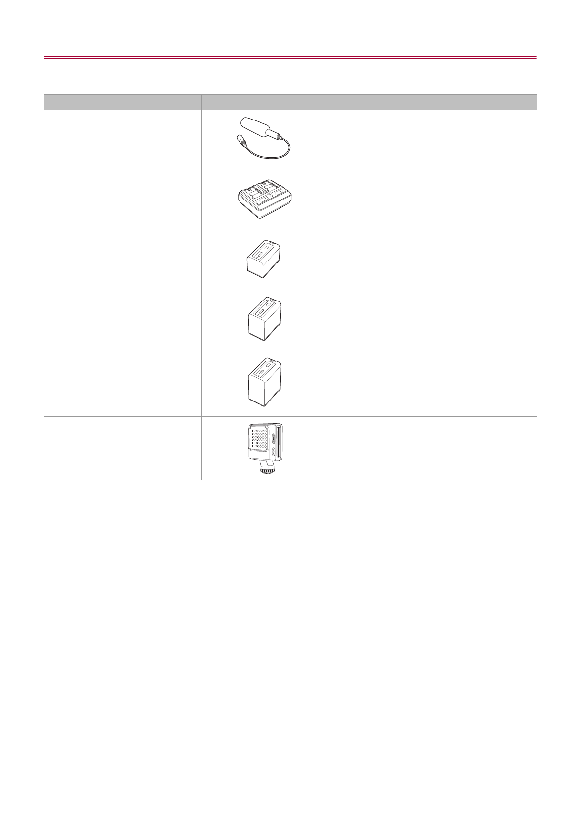
Accessories
Check the accessories before using this unit.
• The accessories and their shape will differ depending on the country or area where the camera was purchased.
For details on the accessories, refer to “Operating Instructions / Owner’s Manual <Quick Start Guide>” (supplied).
≥ Battery pack
≥ Battery charger
*1
≥ AC adaptor
≥ AC cable
• For AC adaptor
≥ Lens hood
*2
≥ Eye cup
≥ INPUT terminal cap (x2)
≥ Microphone holder
≥ Microphone holder mounting screws
*3
• Length 12 mm (0.47 q) (x2)
*1 The AG-BRD50 is available for purchase as an optional accessory package containing a battery charger, AC adaptor, and
AC cable. Individual battery chargers are sold under the model number SAB0002A. Contact your dealer to purchase them.
*2 Pre-attached to the main unit.
*3 The microphone holder mounting screws are supplied with the microphone holder.
• Appropriately discard the AC cable cap (if attached) and packing materials after taking the product out.
• Keep the microphone holder mounting screws and INPUT terminal cap out of reach of children to prevent swallowing.
Overview – Optional accessories
24
Optional accessories
Some optional accessories may not be available in some countries.
Product numbers correct as of August 2022. These may be subject to change.
Accessory No. Figure Description
AG-MC200G Unidirectional microphone
AG-BRD50 Battery charger
AG-VBR59 Battery pack
AG-VBR89 Battery pack
AG-VBR118 Battery pack
VW-LED1 LED video light
Overview – When turning on the power for the first time
25
When turning on the power for the first time
The time zone, date, and time are not set when the unit is shipped.
[TIME ZONE] is displayed in the LCD monitor when the power is turned on for the first time.
Follow the guidance and make the settings in the order of [TIME ZONE] and then [CLOCK SETTING].
• You can do these operations either with the multidial or by touching the LCD monitor.
≥[TIME ZONE]: 25
≥[CLOCK SETTING]: 25
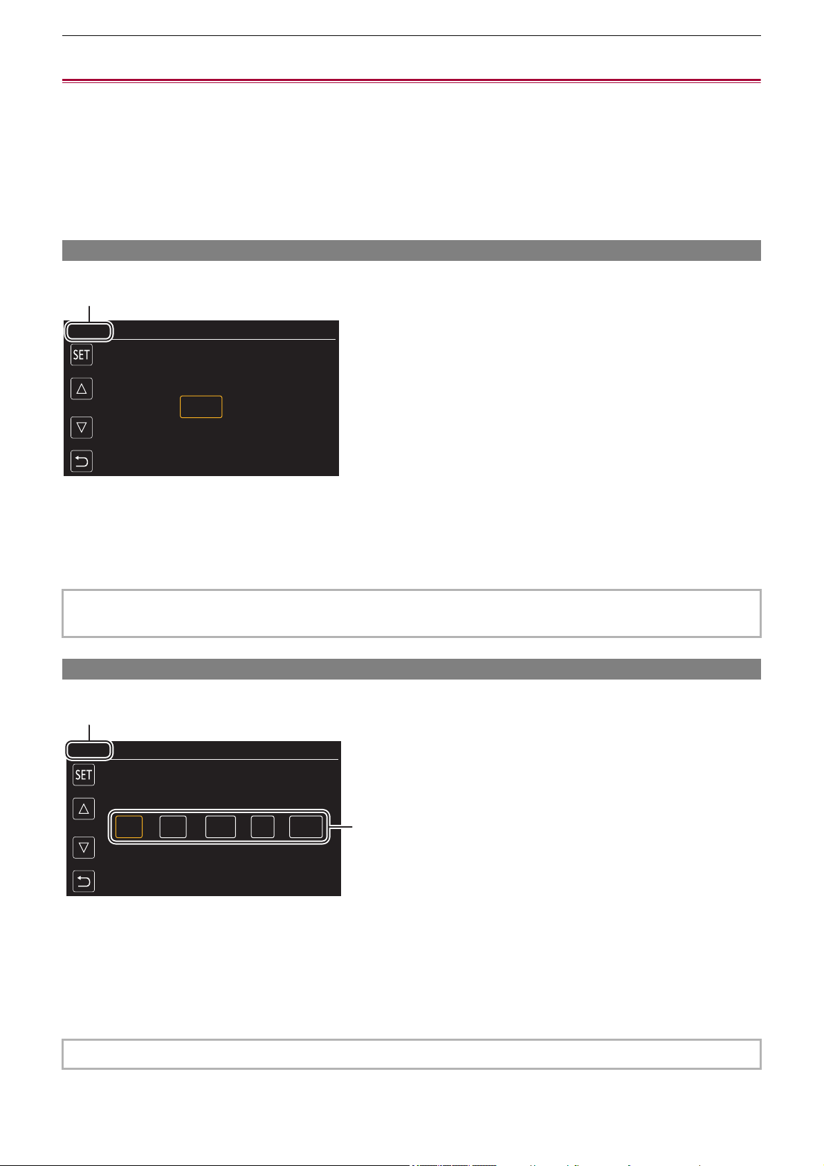
[TIME ZONE]
Set the time difference from the Greenwich Mean Time.
(A) [TIME ZONE]
1
Set the time difference.
2
Select [SET].
Once the setting for [TIME ZONE] is completed, the [CLOCK SETTING] screen is displayed.
[CLOCK SETTING]
Set the year, month, date, and time.
(A) [CLOCK SETTING]
(B) 0 : 0 JAN. 1. 2022
1
Set the year, month, date, and time.
The year can be set between 2021 and 2037.
2
Select [SET].
Once the setting is complete, the camera image screen is displayed.
• The setting for the date/time of the main unit changes together with the time zone settings.
• This can also be set with the [OTHERS] menu
¨ [CLOCK] ¨ [TIME ZONE].
• This can also be set with the [OTHERS] menu
¨ [CLOCK] ¨ [CLOCK SETTING].
ヌパホパパ
(A)
ホ
ハハ
(A)
(B)
Overview – What you can do with this unit
26
What you can do with this unit
≥Recording to the memory card: 26
≥Linking to external devices: 26
≥Connecting to the network: 27
≥USB tethering connection [X2]: 28
Recording to the memory card
Recording in following types is possible.
• MOV recording (UHD and FHD recording)
• MP4 recording (UHD and FHD recording)
• AVCHD recording
• Variable frame rate recording/Super slow recording
• Simultaneous recording
• Relay recording
• Interval recording
• Background recording
• Pre-recording
• (For the )
Dual codec recording
Linking to external devices
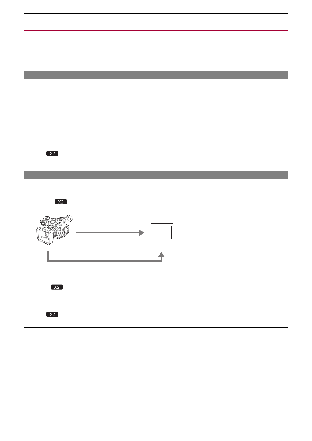
Connecting to TV/monitor
Connect to a TV/monitor and output images.
• When using , use a BNC cable (<SDI OUT> terminal) to connect a TV/monitor.
(A) HDMI cable
(B) (For the )
BNC cable (<SDI OUT> terminal)
(C) TV/Monitor
• Use a commercially-available Premium High Speed HDMI cable.
• (For the )
Use a commercially-available 5C-FB or equivalent double-shielded cable for the BNC cable.
When using a DVI converter, etc., to connect an HDMI cable to this unit, make sure that you connect last to the
<HDMI> terminal on this unit. Connecting first to the <HDMI> terminal on this unit may cause a malfunction.
(A)
(B)
(C)
Overview – What you can do with this unit
27
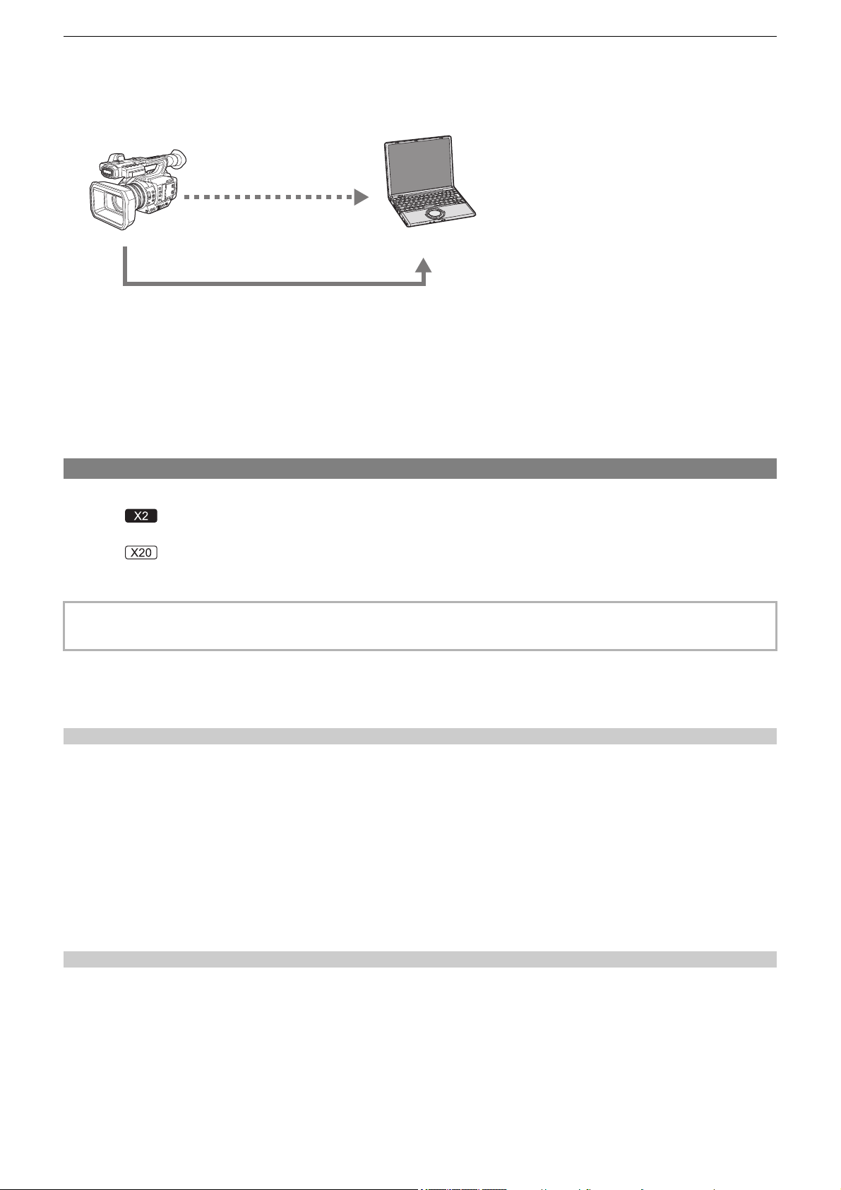
Card reader mode
Data (files) for performing nonlinear editing on a computer are transferred.
• The unit supports USB3.1 Gen1.
(A) Memory card
*1
(B) USB cable
*2
(C) Computer
*1 Memory cards are optionally available. They are not supplied with the unit.
*2 A USB cable is not supplied with the unit.
When using a commercially-available USB cable, use a USB Type-C cable that conforms with USB3.1 and that is a shielded
product with a ferrite core. We recommend using a cable that is within 1.5 m (approx. 4.9 feet) where possible.
Connecting to the network
This unit is equipped with wireless LAN. It can connect to networks via wireless LAN or wired LAN.
• (For the )
When using wired LAN, connect a LAN cable to the <LAN> terminal on this unit.
• (For the )
When using wired LAN, connect a USB ethernet adaptor (commercially available) to this unit, then connect a LAN cable.
Available functions
When the unit is connected to a network, the following functions are available.
Connecting to HC ROP app
You can remotely control this unit with the HC ROP app by connecting this unit with an iPhone/iPad or Android terminal via
network.
• Checking camera status
• Camera remote control (focus, zoom, image quality settings, recording control such as start/end recording, and time code/user
bits settings)
• Menu Operations
• Starting and stopping streaming (when the function is assigned to the USER button)
The unit supports the multi camera function, with which a camera selected from up to 8 cameras is remotely controlled from a
single device.
For details about operation of the HC ROP app, refer to the online help for the app.
Streaming function
You can perform streaming of audio and video currently shot with the unit over a network (wired LAN, wireless LAN).
• Use the following cable to connect to the <LAN> terminal:
– LAN cable (STP (Shielded Twisted Pair), category 5e or above, maximum 100 m (approx. 328 feet))
(A)
(B)
(C)

Overview – What you can do with this unit
28
USB tethering connection [X2]
Connect a USB tethering device (iPhone/iPad or Android device) to the USB terminal of the camera using the USB cable to
connect the camera to the Internet using USB tethering function.
• For information about the tethering function of your smartphone, refer to the operating instructions of the smartphone and
the contract you have with the cell-phone provider. Depending on the contract you have, there may be limitations on
tethering or it may incur large additional charges.
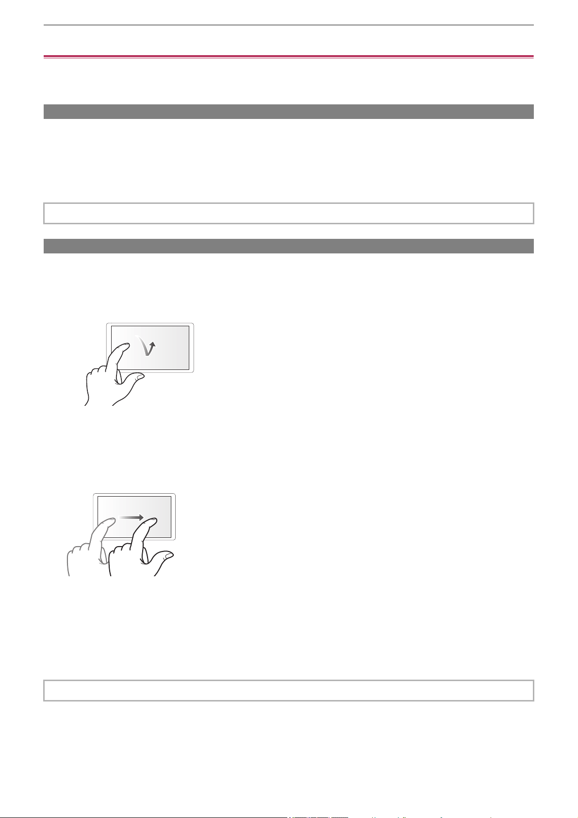
Overview – Basic operation
29
Basic operation
≥Multidial operation: 29
≥Touch operation of the LCD monitor: 29
Multidial operation
Operate the multidial on the main unit by turning it in vertical direction or pushing it.
• Turning the multidial in vertical direction will move the cursor.
• Pressing the multidial will select or confirm the item with cursor.
• Values of the menu or the pages of the thumbnail screen can be changed continuously by pressing and turning the multidial
vertically to fix the setting.
Touch operation of the LCD monitor
The LCD monitor can be operated by directly touching with a finger.
Do not touch the LCD monitor with a pointed hard object such as a ball point pen.
Touching
An operation to press and release the LCD monitor. An item or icon can be selected, or an item can be executed.
• To select an icon, touch the center of the icon.
• It will not operate while touching a different location of the LCD monitor.
Sliding
An operation to move a finger while touching the LCD monitor. Playback operation such as the skip playback or direct playback,
etc. can be performed.
Touching and holding
An operation to keep on pressing, then releasing the LCD monitor. Values of the menu or the pages of the thumbnail screen can
be changed continuously.
• For details about operating the menu (
ÎWhen operating with the multidial: 77)
• For details about operating the menu (
ÎWhen operating by touching the LCD monitor: 78)

30
Preparations before recording
Before you use the unit, attach the battery following the procedures in this chapter. The attaching of accessories is
also described in this chapter.
≥Power supply: 31
≥Attaching accessories: 36
≥Turning the unit on/off: 41
≥Charging the built-in battery: 42
≥Setting the date/time of the internal clock: 43
≥Preparing the memory card: 45
≥Recording time of the memory card: 48
≥Handling the recording data: 50
≥Adjusting and setting the LCD monitor: 53
≥Adjusting and setting the viewfinder: 55
≥Tally lamps: 57
Preparations before recording – Power supply
31
Power supply
A battery or the supplied AC adaptor can be used as the power supply for the unit.
• The unit is compatible to following batteries. (As of August 2022)
– AG-VBR59 (supplied/optional, supports quick charging)
– AG-VBR89/AG-VBR118 (optional, supports quick charging)
• Use the supplied AC adaptor. Do not use the AC adaptor of another device.
• The supplied AC cable is dedicated for this unit. Do not use with any other device. Also, do not use AC cable from other device
on this unit.
≥Charging the battery: 31
≥Attaching and removing the battery: 33
≥Standard charging time and recordable time: 33
≥Connecting to the AC outlet: 35
Charging the battery
The battery is not charged at the time of purchase. Use only after charging sufficiently.
It is recommended that you have one extra battery.
• It is recommended to perform charging of the battery in a location with ambient temperature of 10 °C to 30 °C (50 °F to 86 °F)
(same for the battery temperature).
About the Battery Charger
This unit can charge two battery packs simultaneously and supports quick charging batteries.
(A) CHARGE indicators <CHARGE1/CHARGE2>
Indicate the charge status as follows.
(B) DC IN 12 V connector < >
Connects to the DC plug of the AC adaptor.
It has been found that counterfeit battery packs which look very similar to the genuine product are made available to
purchase in some markets. Some of these battery packs are not adequately protected with internal protection to meet the
requirements of appropriate safety standards. There is a possibility that these battery packs may lead to fire or explosion.
Please be advised that we are not liable for any accident or failure occurring as a result of use of a counterfeit battery pack.
To ensure that safe products are used we would recommend that a genuine Panasonic battery pack is used.
Indicator Charge status
Lit green Quick charging is in progress.
Lit orange Normal charging is in progress.
Blinking orange Charging has stopped due to an error.
Off Charging is complete, or a battery pack is not inserted.
(A)
(B)
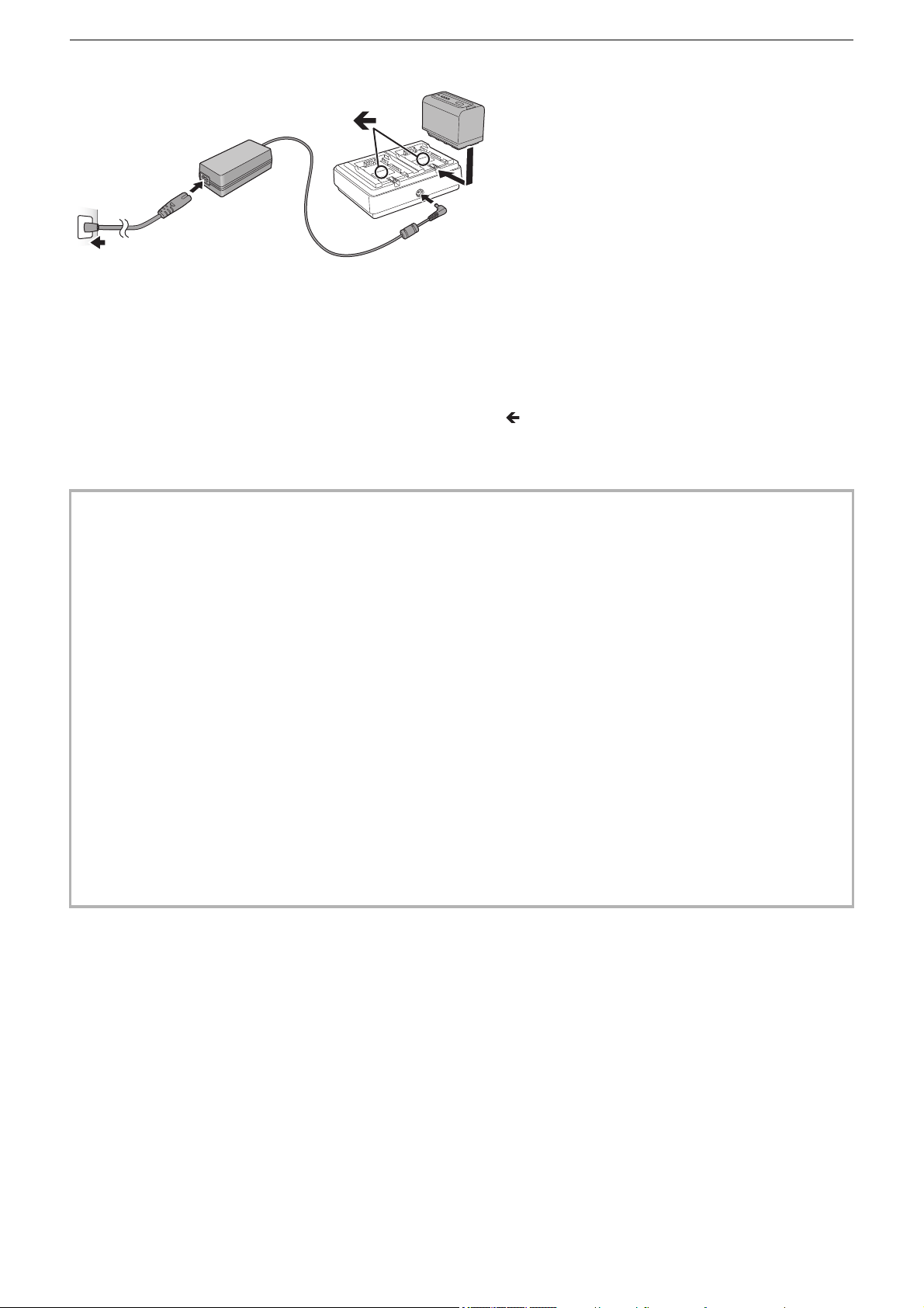
Preparations before recording – Power supply
32
Charging the battery
1
Connect the DC plug of the AC adaptor to the DC IN 12 V connector of battery
charger.
2
Connect the AC mains lead to the AC adaptor.
• Perform step (2) first, and then step (3). Insert the AC mains lead all the way in until it stops.
3
Insert the battery into the battery charger.
• Slide the battery horizontally into the battery charger along the “ ” mark.
• The corresponding CHARGE indicator lights and charging starts.
• The CHARGE indicator turns off when charging is complete. Slide the battery to remove it.
• Do not use any other AC adaptors except the supplied one.
• We recommend using Panasonic batteries (
ÎPower supply: 31).
• If you use other batteries, we cannot guarantee the quality of this product.
• Do not heat or expose to flame.
• Do not leave the battery(ies) in a car exposed to direct sunlight for a long period of time with doors and windows closed.
• Do not expose to low air pressure at high altitudes.
• Do not expose to extremely low air pressure, as this may result in explosions or leakage of flammable liquids and gases.
• The battery charger will determine the status of the battery after the battery is mounted. Therefore, it may take some time
until the charging lamp is to illuminate. Mount the battery again if the charging lamp does not illuminate after ten seconds or
longer has elapsed.
• When two quick charging compatible batteries are mounted, the quick charging on the <CHARGE1> side will take priority,
and the charging on the <CHARGE2> side will be normal charging. Once the charging of the <CHARGE1> side proceeds,
the charging on the <CHARGE2> side will switch to quick charging.
Also, depending on the charging status of the battery, the indicator on the battery that is mounted on the <CHARGE2> side
may turn off.
• The battery charger will perform optimal charging after determining the status of the battery. Once the charging is started,
the indicator for quick charging compatible battery will flash. Also, if it is charging on both <CHARGE1> side and
<CHARGE2> side, charging of both batteries will stop when either one of the battery is mounted/removed, or replaced. It
will start the charging again after determining the status of the batteries.
• Mount the battery to be charged prioritized on the <CHARGE1> side when charging.
(1)
(4)
(2)
(3)
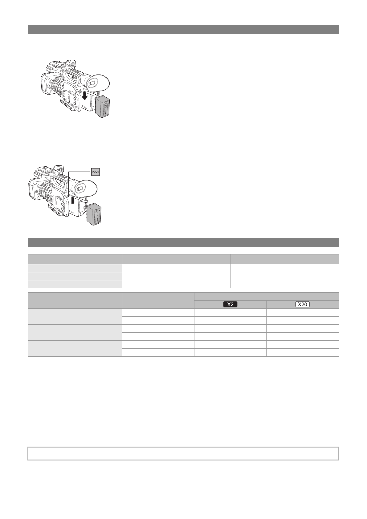
Preparations before recording – Power supply
33
Attaching and removing the battery
1
Install the battery by inserting it in the direction shown in the figure.
• Insert the battery until it clicks and locks.
Removing the battery
Make sure that the power switch is set to <OFF> and the status indicator is turned off, and then remove by holding onto it taking
care not to drop. (
ÎTurning the unit on/off: 41)
• While pressing the battery release button (A), remove the battery.
Standard charging time and recordable time
• “h” is an abbreviation for hour and “min” for minute.
• The charging time is the time when the operating ambient temperature is 25 °C (77 °F) and operating relative humidity is
60 %. At other temperature and humidity the charging time may take longer.
• Continuous recordable time is the time when the unit is used fulfilling all of the following conditions. If you use the unit in other
conditions, continuous recordable time will shorten.
– When set to the factory default menu settings ([FILE FORMAT] is [MOV] and [REC FORMAT] is [2160-59.94p/HEVC
LongGOP 200M]/[2160-50.00p/HEVC LongGOP 200M])
– When the LCD monitor is used and cable is not connected to the external input/output terminal
• The charging time is the time to charge when the charging capacity of the battery is used up. The charging time or
the continuous recordable time differs depending on the use condition such as high or low temperature.
Battery parts number Voltage/capacity (minimum) Charging time
AG-VBR59 (supplied/optional) 7.28 V/5900 mAh Approx. 3 h 20 min
AG-VBR89 (optional) 7.28 V/8850 mAh Approx. 4 h
AG-VBR118 (optional) 7.28 V/11800 mAh Approx. 4 h 40 min
Battery parts number [FREQUENCY]
Continuous recordable time
AG-VBR59 (supplied/optional)
[59.94Hz] Approx. 3 h 50 min Approx. 4 h 25 min
[50.00Hz] Approx. 4 h Approx. 4 h 40 min
AG-VBR89 (optional)
[59.94Hz] Approx. 5 h 45 min Approx. 6 h 35 min
[50.00Hz] Approx. 6 h Approx. 7 h
AG-VBR118 (optional)
[59.94Hz] Approx. 7 h 40 min Approx. 8 h 50 min
[50.00Hz] Approx. 8 h 5 min Approx. 9 h 20 min
• Battery is warm after using or after charging, but this is not a malfunction.
(A)
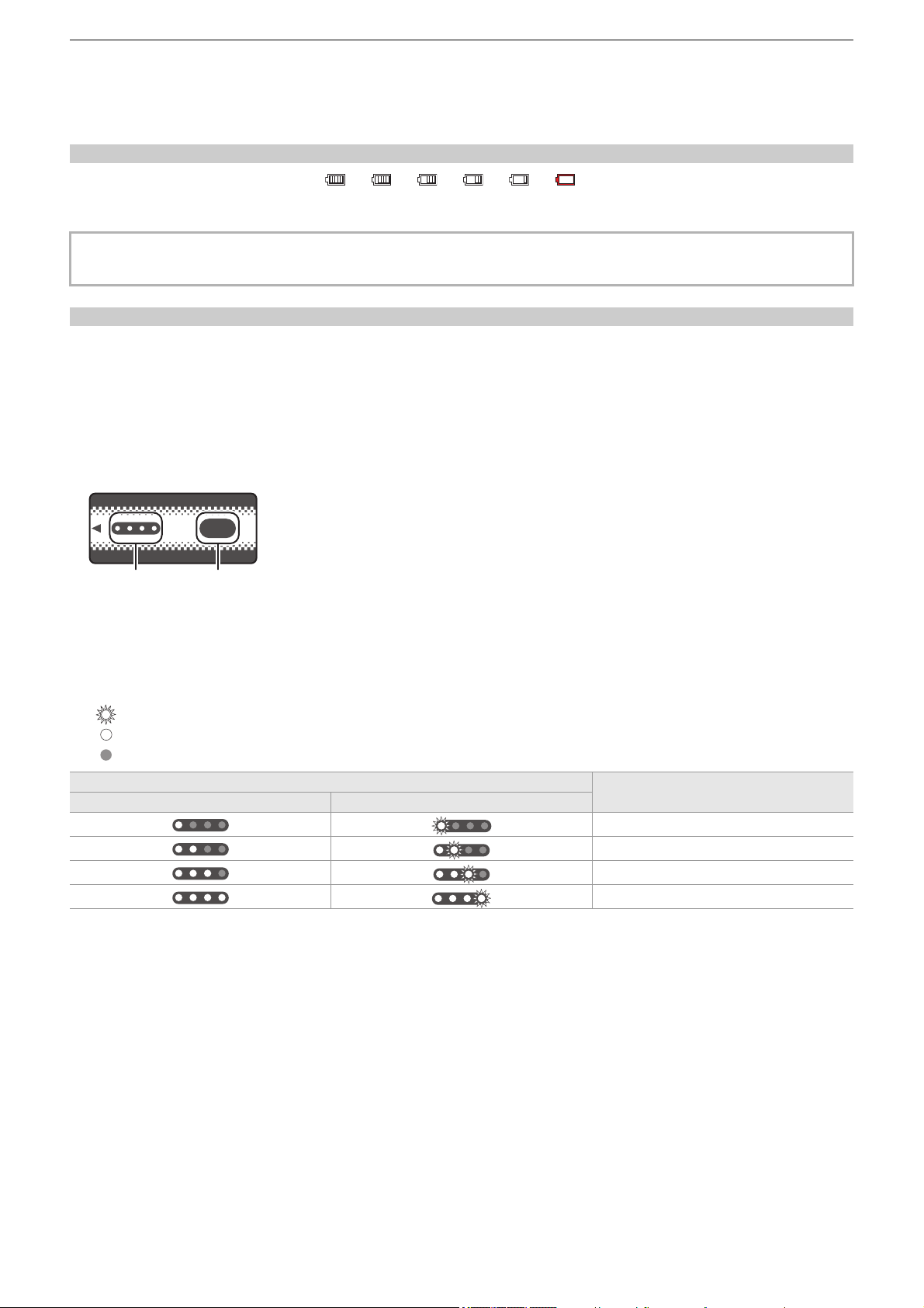
Preparations before recording – Power supply
34
Checking the remaining battery level
The remaining battery level can be checked with the power status display on the LCD monitor or the indicator on the supplied
battery.
Checking the remaining battery level with the LCD monitor
The battery status display will change as
¨ ¨ ¨ ¨ ¨ while the remaining battery level gets lower.
It will flash in red when the remaining battery level is zero.
Checking the remaining battery level with the battery
•
The remaining battery level can be checked with the indicator display by pressing the <CHECK> button on the battery when it
is not charging.
– The remaining battery level is a rough indication.
– The indicator will not illuminate even if the <CHECK> button is pressed when the remaining battery level is zero. Charge the
battery.
• The progress of the charging is notified by the flashing position of the indicator while the battery is charging.
Once the charging is completed, the indicator turns off.
1 Indicator
2 <CHECK> button
Display of the indicator
•
The color and illuminate/flashing status of the indicator indicated by the icon in the table are as follows.
– : Flashing in green
– : Illuminated in green
– : Off
• Display of the indicator is a rough indication. If the battery is attached to the unit or the battery charger, check the remaining
level on the device the battery is attached to. The remaining level may differ from the one displayed with the indicator on the
battery.
• The power status display may not be displayed depending on the setting in the menu.
• Repair or copy of the clip, or update of the firmware is not possible when it is flashing in red.
Indicator display
Remaining battery level/charging progress
When checking the remaining battery level Charging
0% to 25%
25 % to 50 %
50 % to 75 %
75 % to 100 %
ヤラユヤレ
ヤラユヤレ
ヒパパ
テ
パ
1 2
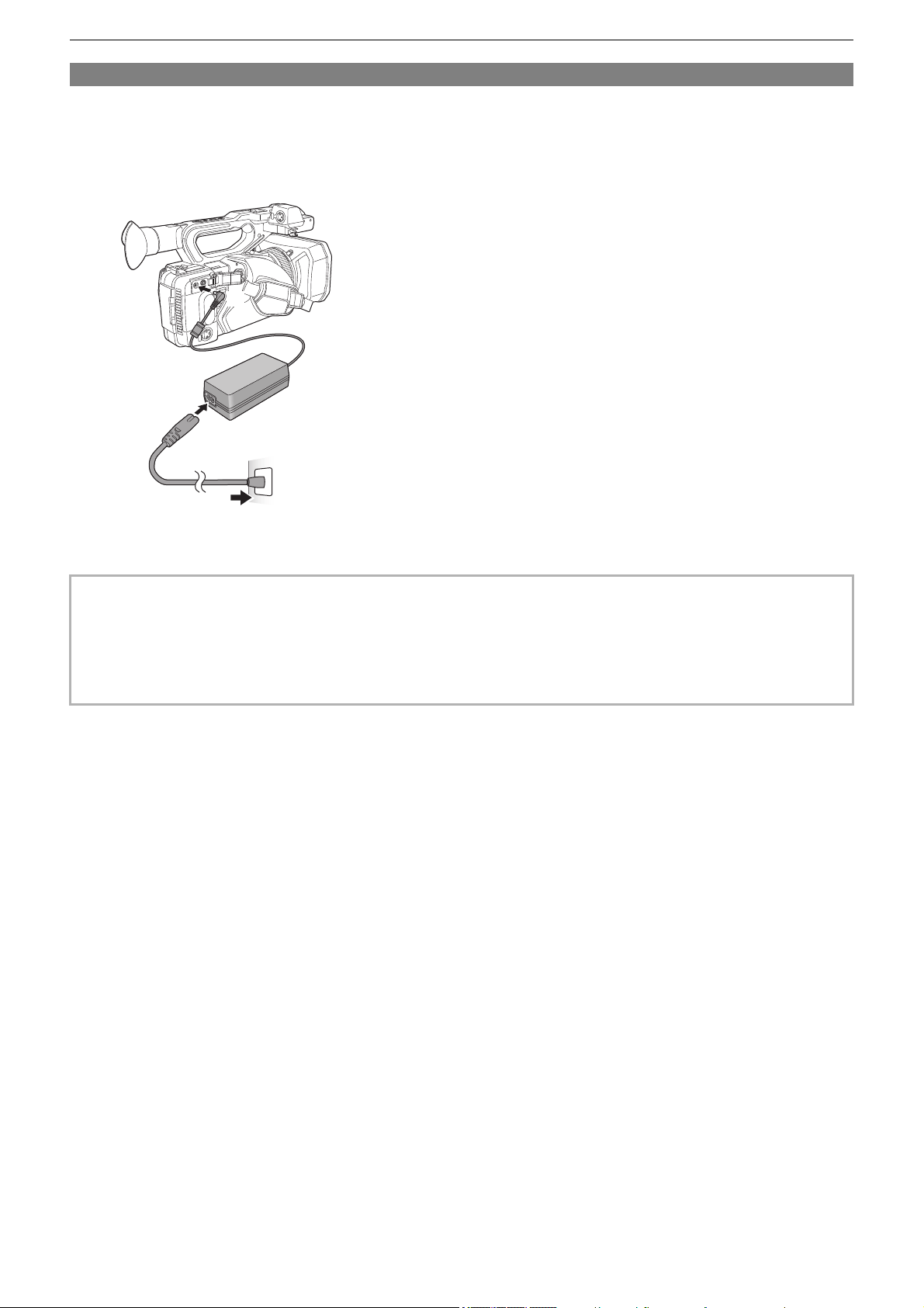
Preparations before recording – Power supply
35
Connecting to the AC outlet
It is possible to use this unit with power supplied from the AC outlet by turning on the unit with the AC adaptor connected.
1
Connect the AC cable to the AC adaptor and the AC outlet.
Insert the plugs as far as they will go.
2
Connect the AC adaptor to the <DC IN 12V> terminal.
• Make sure to set the power switch to <OFF> and the status indicator is turned off when disconnecting the AC adaptor.
(
ÎTurning the unit on/off: 41)
• Even when you use the AC adaptor for recording images, keep the battery connected. This allows you to continue the
recording even if a power failure occurs or the AC adaptor is unplugged from the AC outlet by accident.
• The AC adaptor is in the standby condition when the mains plug is connected. The primary circuit is always “live” as long as
the mains plug is connected to an electrical outlet.
(2)
(3)
(1)

Preparations before recording – Attaching accessories
36
Attaching accessories
≥Adjusting the grip belt: 36
≥Attaching the lens hood: 36
≥Attaching the eye cup: 38
≥Attaching the external microphone: 38
≥Attaching the INPUT terminal cap: 39
≥Attaching a tripod: 40
Adjusting the grip belt
• Adjust the grip belt so that it fits the size of your hand.
• If the buckle is difficult to tighten, move the pad forward and tighten the buckle again.
(A) Pad
(B) Buckle
1
Open the buckle.
2
Pull the end of the belt.
Attaching the lens hood
Removing
(A) Lens hood release button
1
While pressing the lens hood release button, turn the lens hood in the direction of the
arrow to remove it.
(A)
(1) (2)
(B)
(A)
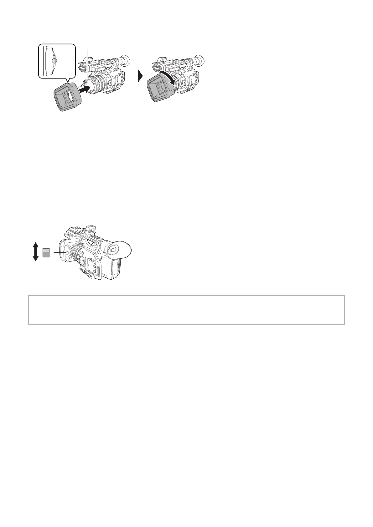
Preparations before recording – Attaching accessories
37
Attaching
(A) Mounting mark
1
Insert the lens hood into the unit.
• Align the mounting marks on the lens hood and unit.
2
Turn the lens hood clockwise.
• Turn until the lens clicks and locks into place.
Opening and closing the lens cover
Use the lens cover opening and closing lever to open and close the lens cover.
Open the lens cover when shooting.
When not using the unit, close the lens cover in order to protect the lens.
• Do not press the lens cover with force. Doing so may damage the lens and lens cover.
• The lens cover may not open and close or the lens hood may not attach depending on the various filters and MC protectors
mounted to the front lens of the unit.
(A)
(A)
OPEN
CLOSE
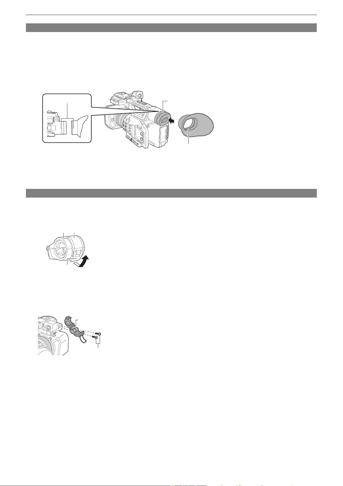
Preparations before recording – Attaching accessories
38
Attaching the eye cup
1
Align the mounting mark on the eye cup with the mounting mark on the eye cup
mount.
2
Attach the eye cup so that the ridge inside it is aligned with the groove on the eye cup
mount.
Push the eye cup in until it reaches the mounting mark.
(A) Ridge
(B) Groove
(C) Mounting mark
Attaching the external microphone
1
Open the microphone holder.
Open buckle (1), and detach fitting (2) from hook (3).
2
Attach the microphone holder to the microphone holder mounting section.
• Attach using a commercially-available screwdriver.
• There will be some rubbing noises with the rubber when screwing in the microphone holder mounting screws, but please
ensure they are done up tightly.
(A) Microphone holder
(B) Microphone holder mounting screws
(B)
(A)
(C)
(1)
(2) (3)
(A)
(B)
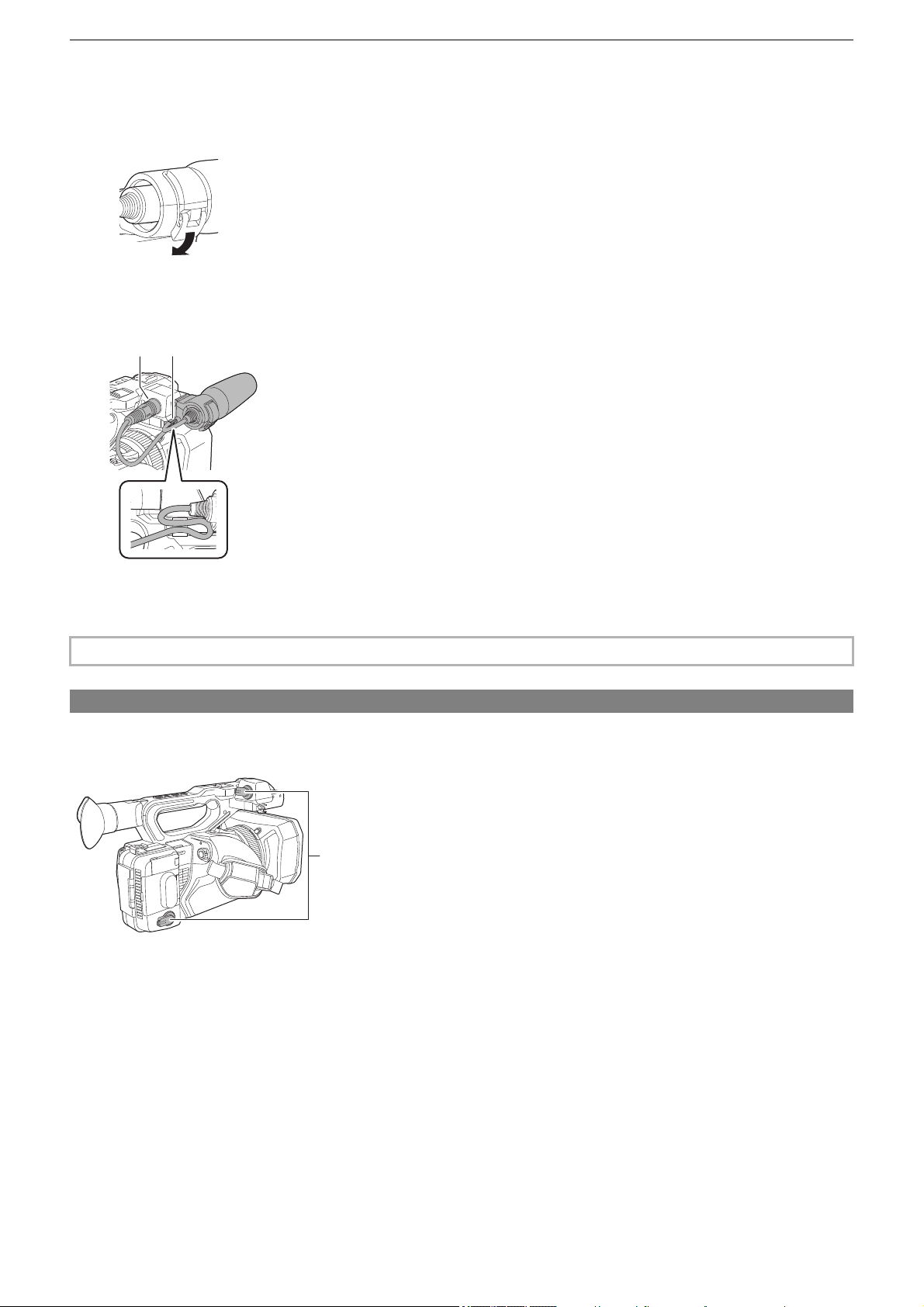
Preparations before recording – Attaching accessories
39
3
Attach the external microphone to the microphone holder, then close the buckle to
secure the external microphone.
Attach the fitting to the hook and close the buckle in the direction indicated by the arrow.
4
Connect the microphone cable to the <AUDIO INPUT1> terminal.
When wiring the microphone cable, use the microphone cable clamp of this unit.
(C) <AUDIO INPUT1> terminal
(D) Microphone cable clamp
Attaching the INPUT terminal cap
Attach the INPUT terminal cap while the <AUDIO INPUT1> terminal/<AUDIO INPUT2> terminal (XLR 3 pin) are
not used.
(A) INPUT terminal cap
• Remove the microphone cable from the <AUDIO INPUT1> terminal while pushing the lever.
(D)(C)
(A)

Preparations before recording – Attaching accessories
40
Attaching a tripod
The tripod mounting holes accept 1/4-20 UNC and 3/8-16 UNC screws.
• Use a tripod in safe locations.
• The depth of the tripod mounting holes is 5.5 mm (0.22 q). Do not over-tighten the tripod screw when attaching the unit to a
tripod.
• Attaching a tripod with a screw length of 5.5 mm (0.22 q) or more may damage the unit.

Preparations before recording – Turning the unit on/off
41
Turning the unit on/off
1
Set the power switch to <ON> while pressing the lock release button (A) to turn on
the unit.
The status indicator (B) lights on.
To turn off the unit
Set the power switch to <OFF> while pressing the lock release button. The status indicator goes off.
• The [TIME ZONE] screen is displayed when the power is turned on for the first time. (
Î[TIME ZONE]: 25)
Set the time zone, date, and time.
• The built-in battery (rechargeable battery) will discharge. The setting for date/time may be initialized when the unit is not
turned on for approximately 4 months.
Set the date/time again after charging the built-in battery. (
ÎSetting the date/time of the internal clock: 43)
• To turn on the power again after [ECO MODE] functions, first switch the power switch to <OFF>, then switch it back to
<ON>.
ON
OFF
(A)
(B)

Preparations before recording – Charging the built-in battery
42
Charging the built-in battery
The date/time set in the unit is maintained by the built-in battery.
If this unit is left without turning the power on, and then when you turn the power on and [BACKUP BATT EMPTY] is displayed
on the viewfinder and LCD monitor for approximately 5 seconds, the built-in battery is exhausted.
The date of the internal clock of the unit resets to January 1, 2022 if the built-in battery is exhausted.
Charge the built-in battery with the following procedure.
1
Set the power switch to <OFF> to turn off the unit.
2
Connect a fully charged battery or the AC adaptor to the unit.
• For details about the connection of the battery or AC adaptor (
ÎAttaching and removing the battery: 33,
Connecting to the AC outlet: 35)
3
Leave the unit for approximately 24 hours.
The built-in battery will be charged.
The built-in battery recharges even when the power is on.
Check the date/time setting and the time code after charging. If [INTERNAL CLOCK HAS RESET] [<PLEASE SET TO
CORRECT TIME>] is displayed on the STATUS screen of the mode check, set the date/time of the internal clock.
(
ÎSetting the date/time of the internal clock: 43)
4
Set the power switch to <ON> to turn on the unit, and confirm that [BACKUP BATT
EMPTY] is not displayed on the LCD monitor.
If [BACKUP BATT EMPTY] is still displayed after charging, the built-in battery needs to be replaced. Consult your dealer.

Preparations before recording – Setting the date/time of the internal clock
43
Setting the date/time of the internal clock
The date/time/time zone are recorded as meta data in the clip while shooting.
This will affect the management of recorded clips, so always check and set the date/time and time zone before using the unit for
the first time.
Do not change the setting of the date/time and time zone while shooting.
1
Press the <MENU> button.
The menu is displayed.
2
Select the [OTHERS] menu ¨ [CLOCK] ¨ [TIME ZONE], and set the time difference
from Greenwich Mean Time.
3
Select the [OTHERS] menu ¨ [CLOCK] ¨ [CLOCK SETTING], and set the year, month,
date, and time.
Time zone table
Time difference Region
+0:00 Greenwich
−0:30
−1:00 Azores
−1:30
−2:00 Mid-Atlantic
−2:30
−3:00 Buenos Aires
−3:30 Newfoundland
−4:00 Halifax
−4:30 Caracas
−5:00 New York
−5:30
−6:00 Chicago
−6:30
−7:00 Denver
−7:30
−8:00 Los Angeles
−8:30
−9:00 Alaska
−9:30 Marquesas Islands
−10:00 Hawaii
−10:30
−11:00 Midway Islands
−11:30
−12:00 Kwajalein Atoll
+0:30
+1:00 Central Europe
+1:30
+2:00 Eastern Europe
+2:30
+3:00 Moscow
+3:30 Tehran
+4:00 Abu Dhabi
+4:30 Kabul
+5:00 Islamabad
+5:30 Mumbai
+6:00 Dhaka
+6:30 Yangon
+7:00 Bangkok
+7:30

Preparations before recording – Setting the date/time of the internal clock
44
+8:00 Beijing
+8:30
+9:00 Tokyo
+9:30 Darwin
+10:00 Guam
+10:30 Lord Howe Island
+11:00 Solomon Islands
+11:30
+12:00 New Zealand
+12:45 Chatham Islands
+13:00 Phoenix Islands
• Accuracy of the clock is approximately ±60 seconds per month. Check and reset the time when accurate time is required.
• Due to the format specifications, with AVCHD format, the following time difference conversions are made for recording with
the clip.
– Time difference set in [TIME ZONE]: +12:45
– Time difference recorded with AVCHD clips: +12:30
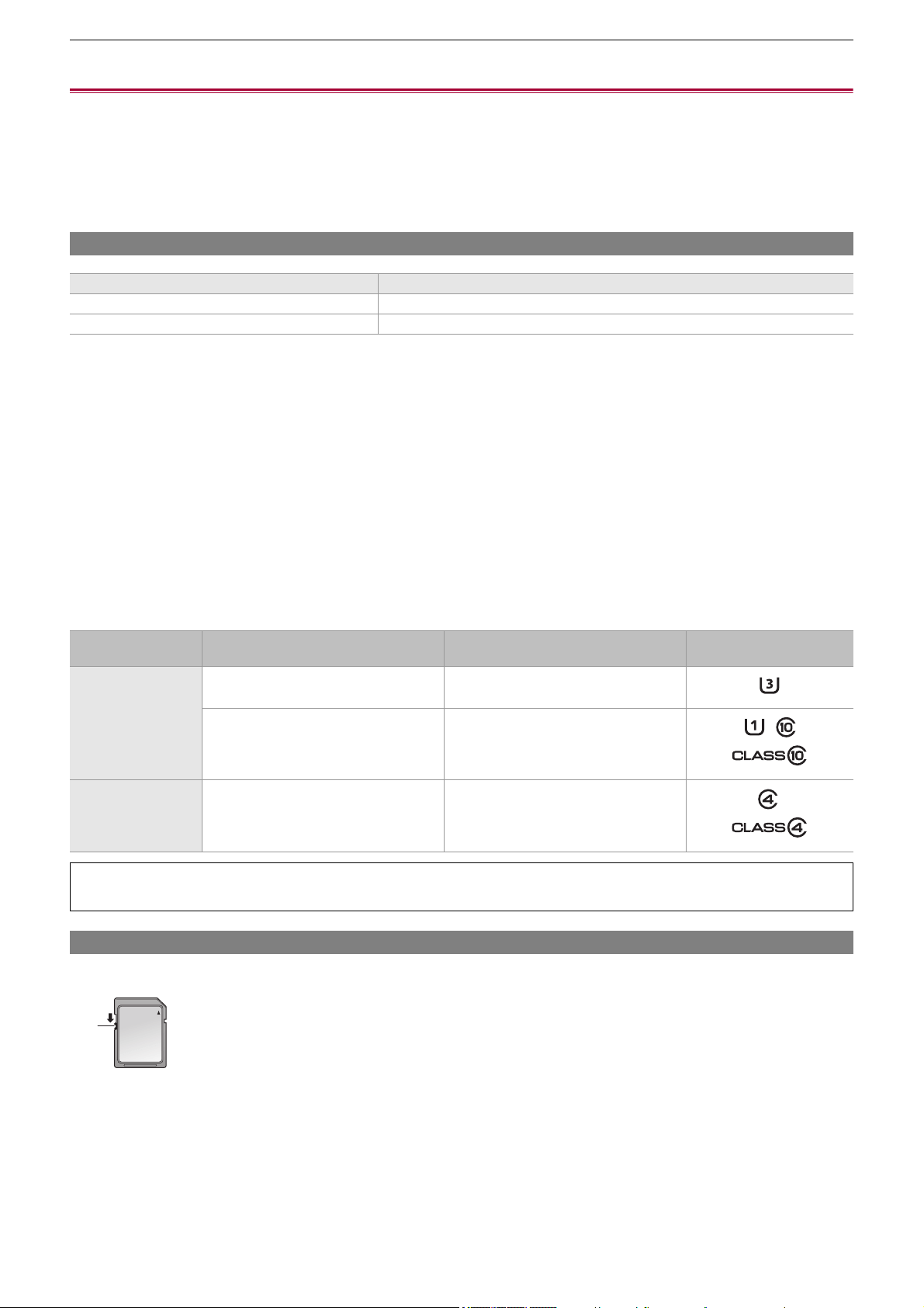
Preparations before recording – Preparing the memory card
45
Preparing the memory card
≥Memory cards supported by the unit (As of August 2022): 45
≥Preventing unintentional erasing: 45
≥Status of the card access lamp and memory card: 46
≥Inserting/removing the memory card: 46
≥Formatting the memory card: 47
Memory cards supported by the unit (As of August 2022)
• Operation is not guaranteed for any memory cards other than the above.
• The following memory cards cannot be used because they do not comply with the SD standards.
– A memory card with 4 GB or more without the SDHC logo
– A memory card with 48 GB or more without the SDXC logo
• This unit supports the following memory cards:
– SDHC/SDXC memory cards that conform with the UHS-I UHS Speed Class 3 standard
• Keep the memory card out of reach of children to prevent swallowing.
Speed Class during shooting
The memory card to use differs depending on the file format and the recording format.
Use memory cards compatible with the Speed Class or UHS Speed Class.
The recording may stop suddenly when a memory card not compatible with the required Speed Class is used.
Speed Class and UHS Speed Class are the speed specification regarding continuous writing. Check the display on the label and
other information on the memory card.
Preventing unintentional erasing
Writing, erasing and formatting data is prohibited by setting the write-protection switch of the memory card to the LOCK side.
(A) Write-protection switch
Type of the memory card Recording capacity
SDHC memory card 4 GB to 32 GB
SDXC memory card 48 GB to 128 GB
File format
Recording bit rate or recording
function
Supported memory cards and Speed
Classes
Example of card display
MOV/MP4
200 Mbps, 150 Mbps, 100 Mbps,
Super slow recording, VFR recording
• SDXC memory card with UHS Speed
Class 3
72 Mbps, 50 Mbps
• SDXC memory card with UHS Speed
Class 1 or better
• SDXC memory card with Speed Class
10
AVCHD All
• SDHC/SDXC memory card with Speed
Class 4 or better
When the file format is MOV or MP4
• SDXC memory cards can be used. SDHC memory cards cannot be used.
(A)
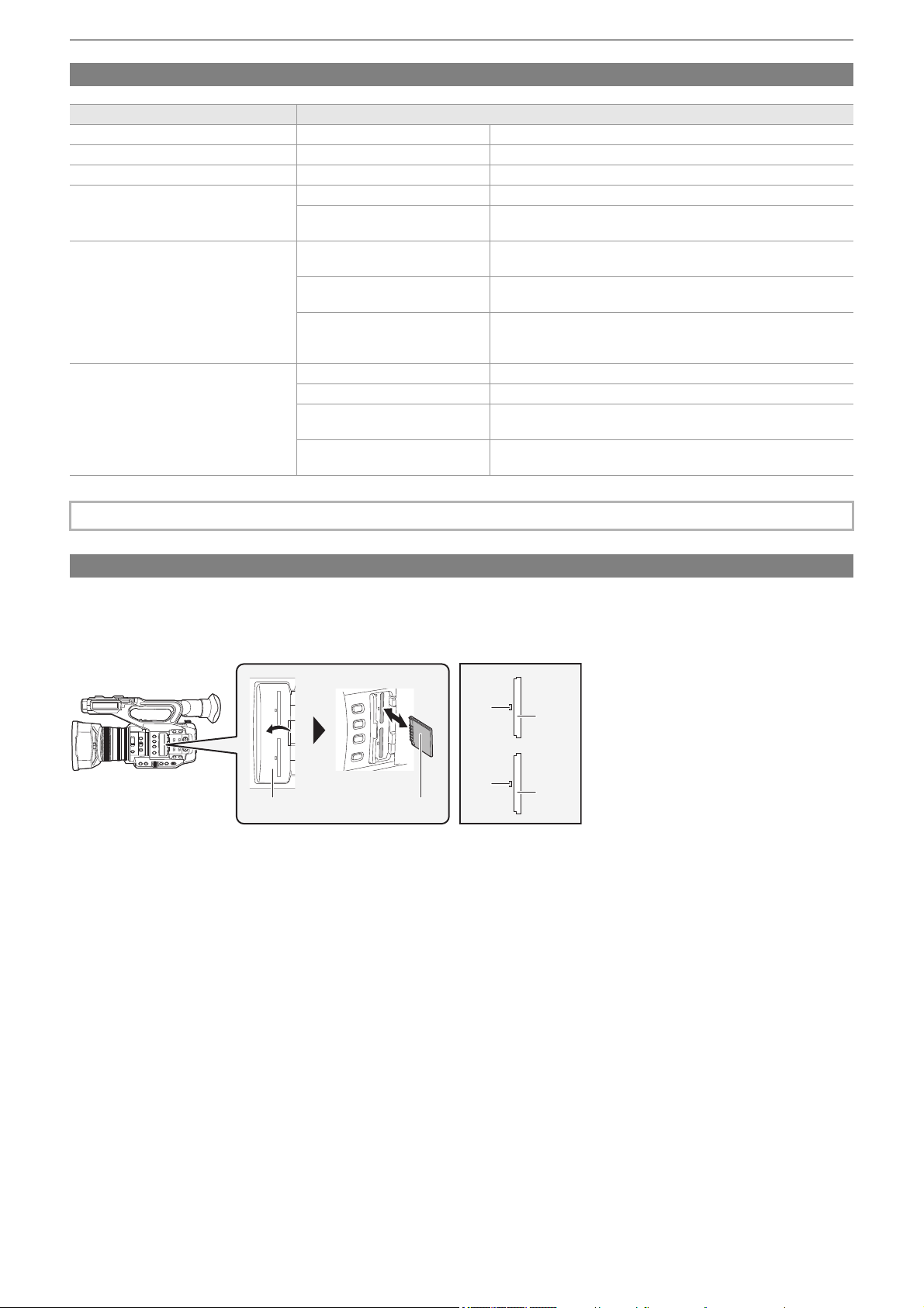
Preparations before recording – Preparing the memory card
46
Status of the card access lamp and memory card
Inserting/removing the memory card
Inserting the memory card
The memory card to use with the unit should always be formatted on the unit. (
ÎFormatting the memory card: 47)
• Formatting the memory card will erase all of the recorded data which cannot be restored.
(A) Card slot cover
(B) Terminal side
(C) Card 1 access lamp
(D) Card slot 1
(E) Card 2 access lamp
(F) Card slot 2
1
Open the card slot cover.
2
Insert the memory card into the card slot.
• Card slot 1 and card slot 2 can each insert one memory card.
• With the terminal facing in the direction indicated in the diagram, push in until there is a click.
Do not force or apply excess force when inserting the memory card.
3
Close the card slot cover.
Card access lamp Memory card status
Orange (illuminated) Recording target Both loading/writing are permitted. Current recording target.
Green (illuminated) Recording possible Both loading/writing are permitted.
Orange (flashing) Accessing card Loading/writing are currently being performed.
Orange (rapidly flashing)
Recognizing memory card The memory card is being recognized.
Error
An error has occurred. This will flash even if the memory card is
not inserted when an error has occurred.
Green (slowly flashing)
No remaining recording capacity
No recording capacity left on the memory card. Only loading is
possible.
Write-protected
The write-protection switch of the memory card is set to the
LOCK side.
Recording not possible
It cannot record with the recording format that is currently set.
Change the recording format or use a memory card compatible
with the recording format to record.
Off
No memory card inserted A memory card has not been inserted.
Illegal format It is not the correct format. Reformat the card.
Card not supported
This is a card that cannot be used with the unit, such as MMC
(Multi Media Card).
During card reader mode
The card 1 access lamp/card 2 access lamp turns off when not
accessing.
• The card access lamps will not illuminate or flash when the [OTHERS] menu
¨ [LED] ¨ [ACCESS LED] ¨ [OFF] is set.
(A) (B)
(C)
(D)
(E)
(F)
Preparations before recording – Preparing the memory card
47
Removing the memory card
1
Open the card slot cover.
• Confirm that the card access lamp is not flashing in orange.
• Data is being written/loaded when the card access lamp is flashing in orange, so do not remove the memory card.
2
Press in the memory card further into the main unit and let go.
• Pull the memory card straight out when it is released from the card slot.
3
Close the card slot cover.
Cautions when using or storing
• Do not touch the connecting terminal section at the rear of the memory card.
• Avoid high temperature and humidity.
• Avoid water droplets.
• Avoid charging with electricity.
Use or store the memory card with the card inserted into the unit and with the slot cover closed.
Formatting the memory card
Before recording with a memory card that is to be used for the first time in this unit, format it.
All data will be deleted when the card is formatted. Save any important data to a computer, etc. (ÎConnection with a computer
in card reader mode: 263
)
• When using 2 memory cards, you must format both of the memory cards.
1
Select the [RECORDING] menu ¨ [FORMAT MEDIA] ¨ [SLOT1]/[SLOT2].
2
When the confirmation message is displayed, select [SET].
3
When the completion message is displayed, select [ ].
• Do not turn this unit off or remove the memory card, while formatting. Do not expose the unit to vibrations or shock.
• This function can be operated also by touching the LCD monitor.
• It may take few seconds after closing the completion message until it can record.
Format the cards using this unit. (Do not format using other devices, such as a computer, etc. Doing so may make
the cards unusable in this unit.)

Preparations before recording – Recording time of the memory card
48
Recording time of the memory card
• Memory cards are only mentioned with their main memory size. The stated times are the approximate recordable times for
continuous recording.
• If recording for long periods, prepare batteries for 3 or 4 times the period you wish to record for. (
ÎStandard charging time and
recordable time: 33
)
• The recordable time may be reduced if recording with a lot of action is recorded or recording of short clip is repeated.
• The recordable times depends on the recording condition or memory card type to be recorded.
• For the resolutions, frame rates, and bit rates for [REC FORMAT] (
ÎSelecting the resolution, codec, and frame rate for
recording video: 146
)
• For the memory cards compatible with the different file formats (
ÎSpeed Class during shooting: 45)
When the file format is MOV
• “h” is an abbreviation for hour and “min” for minute.
When the file format is MP4
• “h” is an abbreviation for hour and “min” for minute.
Recording format Recording rate
Recording capacity
64 GB 128 GB
UHD
200 Mbps Approx. 40 min Approx. 1 h 20 min
150 Mbps Approx. 55 min Approx. 1 h 50 min
100 Mbps Approx. 1 h 20 min Approx. 2 h 40 min
FHD
200 Mbps Approx. 40 min Approx. 1 h 20 min
100 Mbps Approx. 1 h 20 min Approx. 2 h 40 min
50 Mbps Approx. 2 h 40 min Approx. 5 h 20 min
• The recording time will change depending on the frame rate set in the variable frame rate recording or the super slow
recording.
• File is split approximately every 3 hours for the data in MOV format.
These are displayed as separate clips in the thumbnail screen. In addition, the clips recorded across 2 memory cards using
the relay recording are displayed as separate clips.
• The recording is stopped once when the recording time reaches 10 hours, and recording is automatically resumed after few
seconds. Image and audio during the pause will not be recorded. This includes the case of special recording, such as
variable frame rate recording, super slow recording or relay recording.
When performing high-speed shooting with the variable frame rate recording or super slow recording, the recording time will
be shorter than 10 hours depending on the ratio of the frame rate of the recording format and the variable frame rate.
• In the interval recording, the recording is stopped once when the length of a clip reaches 10 hours, and recording is
automatically resumed after few seconds.
Recording format Recording rate
Recording capacity
64 GB 128 GB
UHD
100 Mbps Approx. 1 h 20 min Approx. 2 h 40 min
72 Mbps Approx. 1 h 50 min Approx. 3 h 40 min
FHD 50 Mbps Approx. 2 h 40 min Approx. 5 h 20 min
• File is split approximately every 3 hours for the data in MP4 format.
These are displayed as separate clips in the thumbnail screen. In addition, the clips recorded across 2 memory cards using
the relay recording are displayed as separate clips.
• The recording is stopped once when the recording time reaches 10 hours, and recording is automatically resumed after few
seconds. Image and audio during the pause will not be recorded. This includes the case of special recording, such as relay
recording.
• In the interval recording, the recording is stopped once when the length of a clip reaches 10 hours, and recording is
automatically resumed after few seconds.

Preparations before recording – Recording time of the memory card
49
When the file format is AVCHD
For SDHC memory card
For SDXC memory card
•
“h” is an abbreviation for hour and “min” for minute.
Recording format Recording rate
Recording capacity
4GB 8GB 16 GB 32 GB
PS 25 Mbps Approx. 19 min Approx. 40 min Approx. 1 h 20 min Approx. 2 h 40 min
PH 21 Mbps Approx. 21 min Approx. 46 min Approx. 1 h 30 min Approx. 3 h
HA 17 Mbps Approx. 30 min Approx. 1 h Approx. 2 h Approx. 4 h 10 min
PM 8 Mbps Approx. 1 h Approx. 2 h Approx. 4 h 15 min Approx. 8 h 30 min
Recording format Recording rate
Recording capacity
64 GB 128 GB
PS 25 Mbps Approx. 5 h 20 min Approx. 11 h
PH 21 Mbps Approx. 6 h Approx. 12 h 30 min
HA 17 Mbps Approx. 8 h 30 min Approx. 17 h
PM 8 Mbps Approx. 17 h 10 min Approx. 35 h
• File is split approximately every 4 GB for the data in AVCHD format.
These are displayed as one clip in the thumbnail screen. However, the clips recorded across 2 memory cards using the
relay recording are displayed as separate clips.
• The recording is stopped once when the recording time reaches 10 hours, and recording is automatically resumed after few
seconds. Image and audio during the pause will not be recorded. This includes the case of special recording, such as relay
recording.
• Protection is automatically released on memory cards locked with AVCHD protection such as DVD recorders.
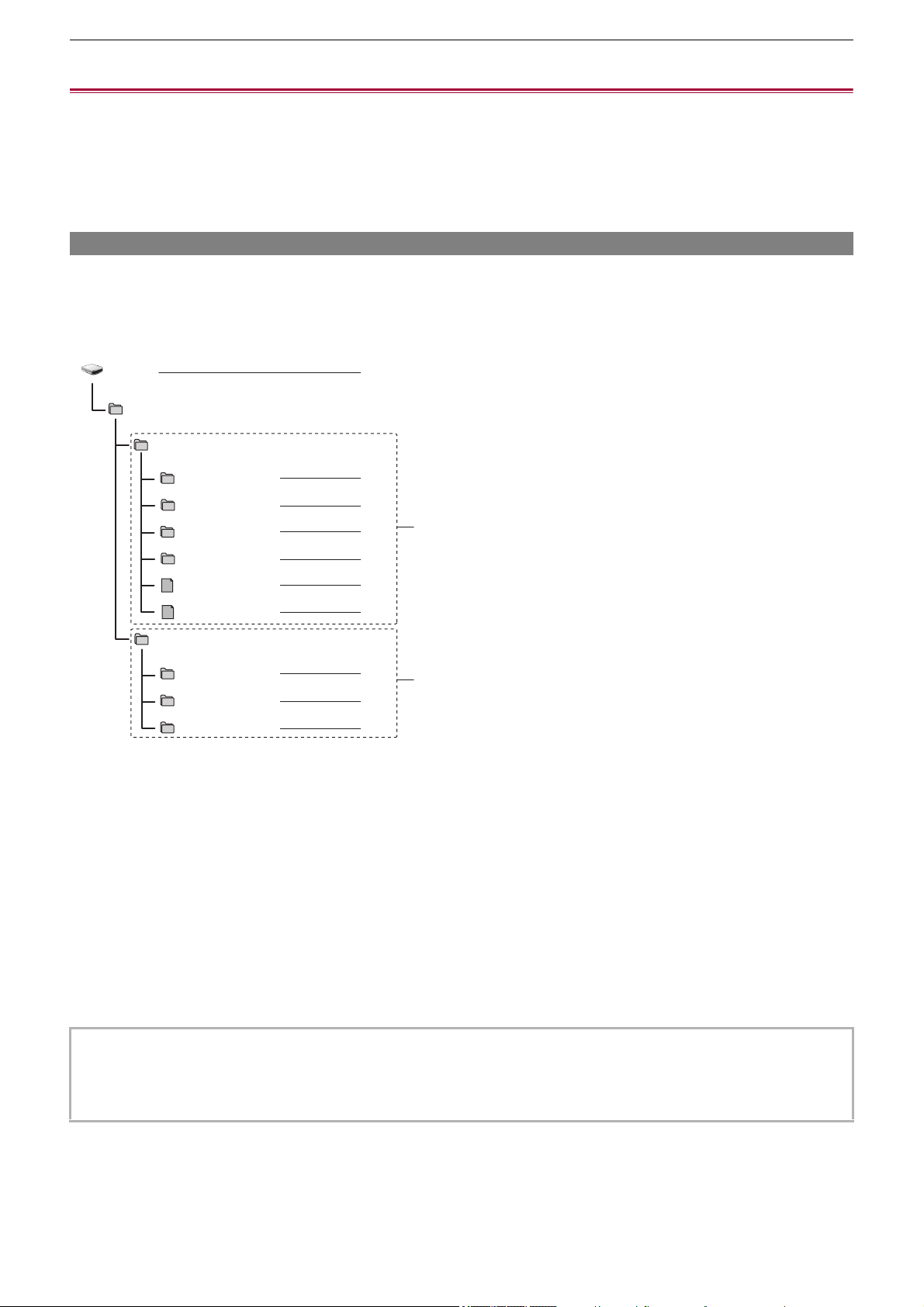
Preparations before recording – Handling the recording data
50
Handling the recording data
≥Folder structure example of a memory card: 50
≥Volume label of the memory card: 51
≥Folder name of the MOV format/MP4 format video data: 51
≥File name of the MOV format/MP4 format video data: 52
≥About the number of clips that can be recorded to a memory card: 52
Folder structure example of a memory card
Various important information is contained in the recording data, and it is linked with the folder structure and management files
as shown in the figure.
If such information is changed or deleted even partially, an error such as that the data cannot be recognized or the recording
becomes impossible may occur.
(A) MOV/MP4 format
(B) AVCHD format
1 Volume label of the memory card
2 Video data in MOV format: UHD (3840×2160), 29.97p MOV (audio: LPCM)
3 Video data in MOV format: FHD (1920×1080), 59.94i MOV (audio: LPCM)
4 Video data in MP4 format: UHD (3840×2160), 29.97p MP4 (audio: AAC)
5 Video data in MP4 format: FHD (1920×1080), 59.94p MP4 (audio: AAC)
6 Management file 1
7 Management file 2
8 Thumbnail of video data
9 Video data in AVCHD standard (00000.MTS, etc.)
10 Management folder
• Do not erase a folder or file on the memory card with a computer. It may make it impossible to load on the unit.
• If data is recorded to the memory card with a computer, an error may occur such as an inability to recognize or record to the
memory card with the unit.
• The memory card to use with the unit should always be formatted on the unit.
B002
PRIVATE
PANA_GRP
003RCPAM
004YAPAM
BACKUP.TMP
INDEX.DAT
AVCHD
AVCHDTN
BDMV
PANA_EXT
1
2
3
4
5
6
7
8
9
10
001RCQAM
002YCJAM
(A)
(B)
Preparations before recording – Handling the recording data
51
Volume label of the memory card
When the file format is MOV or MP4
The value set in the [RECORDING] menu
¨ [CLIP NAME] is stored in the volume label in the CAM INDEX+NEXT CARD
COUNT format when the memory card is formatted. Once it is stored, [NEXT CARD COUNT] will increase by one. The CARD
COUNT that is stored is also used for the CARD number of the MOV format/MP4 format file name.
When the file format is AVCHD
“CAM_SD” is stored in the volume label.
Folder name of the MOV format/MP4 format video data
The fourth through eighth characters of the folder name differ depending on the setting of the unit.
1 Folder number
001 to 999 (sequential number)
2 Number of pixels
R: 3840×2160
Y: 1920×1080
3 Frame rate
A: 59.94 fps
B: 50.00 fps
C: 29.97 fps
D: 25.00 fps
F: 23.98 fps
4 Video format
P: Progressive recording (MP4, AAC)
Q: Progressive recording (MOV, LPCM)
I: Interlace recording (MP4, AAC)
J: Interlace recording (MOV, LPCM)
5 Fixed value
A
6 Recording setting
(For the )
M: Standard recording, simultaneous recording (card slot 1), dual codec recording (main recording)
S: Dual codec recording (sub recording)
T: Simultaneous recording (card slot 2)
(For the )
M: Standard recording, simultaneous recording (card slot 1)
T: Simultaneous recording (card slot 2)
7 Recording format information
When the folder name is 001RAQAM
Following video data is saved in the folder.
• Number of pixels: 3840×2160
• Frame rate: 59.94 fps
• Video format: Progressive recording (MOV, LPCM)
• When recording to the memory card that CAM INDEX+CARD COUNT is not stored in the volume label, the value set in the
[RECORDING] menu
¨ [CLIP NAME] is automatically stored in the volume label, and [NEXT CARD COUNT] will increase
by one.
001RAQAM
1 23456
7

Preparations before recording – Handling the recording data
52
File name of the MOV format/MP4 format video data
The format of the file name is as follows.
1 CAM INDEX
One character from upper case A to Z.
• An INDEX assigned to each camera. Set with the [RECORDING] menu ¨ [CLIP NAME] ¨ [CAM INDEX].
2 CARD number
001 to 999
• This is the number assigned to each memory card. The CARD COUNT stored in the volume label of the memory card is
assigned.
3 Clip number
C001 to C999
• This is a sequential number assigned to each recording on the memory card. The number returns to C001 when the
memory card is formatted.
It will also return to C001 for the one after C999.
The clip number is maintained even when the folder is split or when the clip is deleted.
4 Date
Last 2 digits of year + 2 digits of month + 2 digits of date when the recording is started.
5 Hashtag generated from the serial number
4-digit number or alphabet
6 File format
[.MOV] or [.MP4]
About the number of clips that can be recorded to a memory card
• When multiple file formats are recorded to a single memory card, the number will be less than that shown above.
About MOV/MP4 folders
The maximum number of folder and the folder number is 999. The recording is prohibited when it reaches 999 even if number in
between is open.
• The upper limit for the number of clips that can be recorded in a single folder is 999. Once it reaches 999, a folder with
sequential number added is newly created.
Also, a folder with sequential number added is newly created when the folder name is changed by changing the setting of the
unit.
The folder number will return to 001 when the memory card is formatted.
About AVCHD playlists
When recording with AVCHD, playlists are generated. The upper limit for the number of clips that can be recorded in a single
playlist is 99.
• A new playlist is generated in the following cases.
– When the [REC FORMAT] is changed for recording
– When recording with interval recording
– When a memory card that has been used in this unit is recorded to with another device
– When the total recording time in a single playlist reaches 11 hours 30 minutes
• The upper limit for the number of playlists is 900. Recording is prohibited when the number of playlists reaches 900.
• The clip name of the card slot 2 will be the same as the clip name of the card slot 1 for the simultaneous recording.
File format Number of clips
MOV
Approx. 4000
• The total number of clips for MOV and MP4.
MP4
AVCHD Approx. 3900
B002C010_200918_E125
.MOV
21 634 5
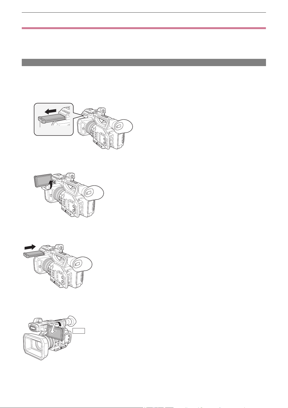
Preparations before recording – Adjusting and setting the LCD monitor
53
Adjusting and setting the LCD monitor
≥Using the LCD monitor: 53
≥Adjusting the LCD monitor: 54
≥Mirror shooting: 54
Using the LCD monitor
This unit is equipped with a 3.5-inch LCD monitor. Use either the viewfinder or the LCD monitor depending on your purpose and
the shooting conditions.
1
Extract the LCD monitor in the direction as indicated in the figure.
Hold the LCD monitor extractor, and extract the LCD monitor until it clicks into position.
(A) LCD monitor extractor
2
Rotate to the position that is easy to view.
To retract the LCD monitor
Retract as shown in the figure with the LCD facing downward.
Range of rotation of the LCD monitor
It can rotate up to 270o towards the lens.
(A)
270°

Preparations before recording – Adjusting and setting the LCD monitor
54
Adjusting the LCD monitor
Adjusting brightness, contrast, color level, redness, and blueness
By setting the following items in the [VIDEO OUT/LCD/VF] menu
¨ [LCD], you can adjust items such as brightness and contrast
for the LCD monitor:
[BRIGHTNESS]:
Adjusts the brightness.
[COLOR LEVEL]:
Adjusts the density of the colors.
[CONTRAST]:
Adjusts the contrast.
[RED TINT]:
Adjusts the strength of red.
[BLUE TINT]:
Adjusts the strength of blue.
The adjustments of the LCD monitor do not affect the images output or recorded by the camera.
Adjusting the backlight luminance
The following operations switch the luminance of the backlight of the LCD monitor:
• Set with the [VIDEO OUT/LCD/VF] menu
¨ [LCD] ¨ [BACK LIGHT].
• Each time you either press the USER button assigned to [LCD BACKLIGHT] or touch the USER button icon, the brightness
switches in the order [0], [1], [2], [-1].
Mirror shooting
When recording with the LCD monitor rotated towards the lens side, if the unit is set to the [VIDEO OUT/LCD/VF] menu ¨ [LCD]
¨ [SELF SHOOT] ¨ [MIRROR], the image is displayed in reverse in left and right on the LCD monitor. This allows shooting as
if looking at a mirror image. Note that only the display of the LCD monitor is horizontally reversed. The settings for mirror
shooting do not affect the images output or recorded by the camera.
• Take care not to apply excessive force on the LCD monitor when it is opened. Doing so may result in a malfunction.
• The image brightness and color hue seen on the viewfinder and LCD monitor may be different from that seen on a TV
monitor. The final check of the image should be done on a TV monitor.
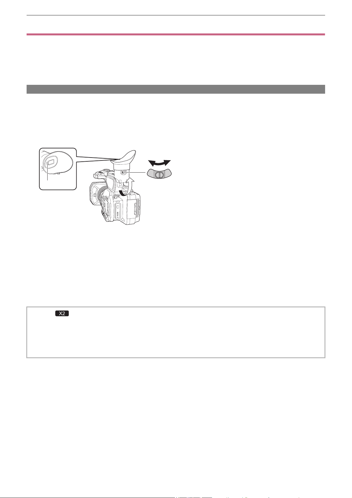
Preparations before recording – Adjusting and setting the viewfinder
55
Adjusting and setting the viewfinder
This unit is equipped with a 0.39-inch organic EL display viewfinder. Use either the viewfinder or the LCD monitor depending on
your purpose and the shooting conditions.
≥Using the viewfinder: 55
≥Adjusting the viewfinder: 56
Using the viewfinder
When the LCD monitor is difficult to use because the surroundings are bright, you can check the image using the viewfinder.
Positioning your eye near the viewfinder will trigger the eye sensor to automatically display the image.
• The sensitivity of the eye sensor is set in the [VIDEO OUT/LCD/VF] menu
¨ [VF] ¨ [EYE SENSOR] ¨ [HIGH] or [LOW].
• The eye sensor may not work properly depending on the shape of the eyeglasses you may be wearing, how you hold the
camera, or by strong light present in the vicinity of the eyepiece. If this happens, switch the image display by assigning [VF
ON/OFF] to the USER button.
(A) Eye sensor
(B) Diopter adjuster lever
1
Move the viewfinder in the vertical direction to adjust the screen to a comfortable
angle.
The viewfinder can be elevated approximately 90°.
2
Adjust the characters on the viewfinder screen so that they are clearly visible using
the diopter adjuster lever.
• (For the )
Set to the following setting when the [VIDEO OUT/LCD/VF] menu
¨ [VIDEO OUT SEL] ¨ [SDI + HDMI OUTPUT] is set to
[ON].
– [VIDEO OUT/LCD/VF] menu ¨ [VIDEO OUT SEL] ¨ [LCD/VF OUTPUT] ¨ [AUTO].
• The image brightness and color hue seen on the viewfinder and LCD monitor may be different from that seen on a TV
monitor. The final check of the image should be done on a TV monitor.
(A) (B)

Preparations before recording – Adjusting and setting the viewfinder
56
Adjusting the viewfinder
Adjusting brightness, contrast, color level, redness, and blueness
By setting the following items in the [VIDEO OUT/LCD/VF] menu
¨ [VF], you can adjust items such as brightness and contrast
for the viewfinder:
[BRIGHTNESS]:
Adjusts the brightness.
[COLOR LEVEL]:
Adjusts the density of the colors.
[CONTRAST]:
Adjusts the contrast.
[RED TINT]:
Adjusts the strength of red.
[BLUE TINT]:
Adjusts the strength of blue.
The adjustments for the viewfinder do not affect the images output or recorded by the camera.
Switching between color and monochrome
The viewfinder screen can switch between a color display and monochrome display. Set the display with the [VIDEO OUT/LCD/
VF] menu
¨ [VF] ¨ [VF COLOR].

Preparations before recording – Tally lamps
57
Tally lamps
The front tally lamp and the rear tally lamp can be illuminated during the shooting.
1
Select the [OTHERS] menu ¨ [LED] ¨ [TALLY LED] ¨[FRONT]/[REAR]/[BOTH].
2
Select the [OTHERS] menu ¨ [LED] ¨ [REC TALLY] ¨[ON]
• The tally lamps will flash when the unit is in the following status.
– When the remaining recording capacity of the memory card or the remaining battery level is low (one time per second)
– When the memory card has no more space to record (4 times per second)
– When a warning such as a system error or a recording abnormality has occurred (4 times per second)
• The tally lamps will not illuminate or flash when the [OTHERS] menu
¨ [LED] ¨ [TALLY LED] ¨ [OFF] is set.

Settings before recording – Setting of time data
59
Setting of time data
The unit provides time code, user bits, and date and time (real time) data as time data, and records in each frame synchronized
with the video. The time data is also recorded as the clip meta data.
≥Definition of time data: 59
≥User bits settings: 60
≥Setting the time code: 61
≥Presetting the time code to external [X2]: 62
≥Supplying the time code externally [X2]: 64
Definition of time data
Time code
[FREE RUN] and [REC RUN] can be switched with the [RECORDING] menu
¨ [TC/UB] ¨ [FREE/REC RUN].
[FREE RUN]:
Advances regardless of the operation mode. It is advancing even when the power is turned off, so it can be treated equally as
time.
• (For the )
Time data can also be recorded to the time code input to the <TC IN/OUT> terminal using slave lock.
[REC RUN]:
Advances only while recording. Recording is started with the value continuing from the last time code recorded previously.
User bits
User bits are built-in. User bits are recorded in the clip.
The user setting value, time, date, time code, and frame rate information of shooting, and the clip name can be selected for
recording.
The value at the time when the recording has started is recorded in the user bits of the clip meta data.
Counter
Press the <COUNTER> button and display the counter to display the counter value in the time code display of the viewfinder/
LCD monitor.
Counter value is displayed as “hour:minute:second.frame”.
In addition, press the <RESET> button while the counter value is displayed to reset the counter value.
Either of the following settings can be set in the [RECORDING] menu
¨ [REC COUNTER].
[TOTAL]:
Counting continues cumulatively until the counter value is reset. The counter value will be maintained even if the memory card
is replaced or the power is turned off.
[CLIP]:
Clears the counter value and starts counting from 0 each time recording starts. You can shoot while always checking the
recording time of the clip you are currently shooting.
• The [REC RUN] will not be a continuous value for following cases.
– When deleting recorded clips
– When recording is interrupted due to a malfunction of [REC WARNING], etc. during recording.
• [REC RUN] is fixed when the variable frame rate recording function or the super slow recording function is enabled.
(
ÎVariable frame rate (VFR) recording function/super slow recording function: 189)
• It will be fixed to [FREE RUN] when pre-recording is enabled. (
ÎPre-recording: 195)
• [FREE RUN] is fixed when the background recording function is enabled. (
ÎBackground recording: 198)
• It will be fixed to [REC RUN] when the interval recording function is enabled. (
ÎInterval recording: 202)

Settings before recording – Setting of time data
60
Date/time (real time)
• The internal clock is the standard while the power is turned off for the free run time code count, the user bits time, and the date
data. Also, it will be the reference for the file generation time and file name when the clip is recorded.
• The free run time code is reset if the built-in battery is exhausted.
User bits settings
Set the user bits to be recorded.
1
Select the user bits to record in the [RECORDING] menu ¨ [TC/UB] ¨ [UB MODE].
[FRAME RATE]:
Records the frame rate information of the shooting.
Use with this setting when using the frame rate information of the user bits with an editing device such as a
computer.
[USER]:
Records the user bits set in the [RECORDING] menu
¨ [TC/UB] ¨ [UB PRESET]. The setting value is
maintained even if the power is turned off.
• For detailed setting procedures (
ÎHow to input user bits: 60)
[TIME]:
Records the hour, minute, and second of the date and time measured with the internal clock.
[DATE]:
Records the last 2 digits of year, month, date, and hour of the date and time measured with the internal clock.
[TC]:
Records the value for the time code as users bits.
[CLIP NAME]:
Records the value that CAM INDEX (one character) and CARD COUNT (3-digit number) both converted to
ASCII character code.
How to input user bits
By setting user bits, information such as memos (date, time) up to 8 digits long (hexadecimal) can be recorded.
1
Select the [RECORDING] menu ¨ [TC/UB] ¨ [UB MODE] ¨ [USER].
2
Select the [RECORDING] menu ¨ [TC/UB] ¨ [UB PRESET].
The user bits setting screen is displayed.
3
Set the user bits.
• Set 2 digits each.
Press the <RESET> button to reset to [00].
4
Confirm the setting value of the user bits.
• The setting value is confirmed when last 2 digits are set.
• The display in the camera image screen is toggled with the <COUNTER> button.
Settings before recording – Setting of time data
61
Memory function of the user bits
The setting content of the user bits is automatically recorded and maintained even if the power is turned off.
Frame rate information
The relationship between frame rate, image pull-down, time code, and user bits is as follows.
(A) Verification information on the right-hand 6 digits
(B) Fixed value
(C) Frame rate
(D) Camera video mode
(E) REC mark
Camera video mode
The display of the camera video mode differs depending on the setting of following menus.
• The [SYSTEM] menu
¨ [REC FORMAT]
• The [SCENE FILE] menu
¨ [VFR] or the [SYSTEM] menu ¨ [SUPER SLOW]
Setting the time code
1
Select the [SYSTEM] menu ¨ [FREQUENCY] ¨ [59.94Hz]/[50.00Hz].
2
From the [SYSTEM] menu ¨ [FILE FORMAT]/[REC FORMAT], select the recording
format.
3
Select the [RECORDING] menu ¨ [TC/UB] ¨ [DF/NDF] ¨ [DF]/[NDF].
[DF]:
Time code is compensated in accordance with the actual time. It is mainly used for broadcasting such as TV
programs.
• Time code display example: TCG 00:00:00.00
[NDF]:
It will not compensate the time code. (There will be a difference from the actual time)
• Time code display example: TCG 00:00:00:00
4
Select the [RECORDING] menu ¨ [TC/UB] ¨ [TC PRESET].
The [TC PRESET] screen is displayed.
5
Set the time code.
Press the <RESET> button to reset the time code to 0.
6
Confirm the setting value of the time code.
The setting value is confirmed when last 2 digits are set.
[FREQUENCY] Frame rate of [REC FORMAT]
Display of camera video mode
When [VFR] or [SUPER SLOW]
is [ON]
When [VFR] and [SUPER
SLOW] are [OFF]
[59.94Hz]
23.98p D C
29.97p 9 8
59.94p 9 8
59.94i — 0
[50.00Hz]
25.00p B A
50.00p B A
50.00i — 2
(A) (B) (C) (D) (E)
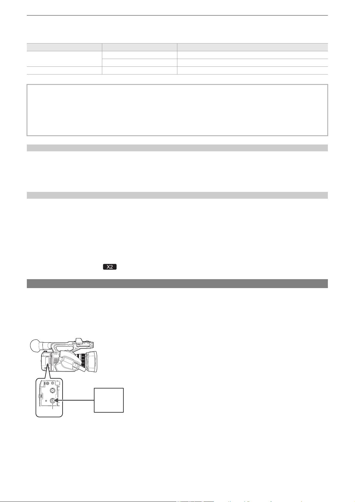
Settings before recording – Setting of time data
62
Setting range of time code
The range of the time code that can be set differs depending on the frame rate of [REC FORMAT].
Time code function during battery replacement
The operation of the time code generator will continue by the backup mechanism functioning even when replacing the battery.
The time code of the free run may shift when any item in the [SYSTEM] menu
¨ [FREQUENCY], [FILE FORMAT], or [REC
FORMAT] is changed.
After turning on the power again with the power switch, check the time code and set again if necessary.
Time code in variable frame rate recording/super slow recording
The time code is fixed to [REC RUN] when the variable frame rate recording function or the super slow recording function is
enabled.
During recording, the time code progresses at a speed according to a ratio of the frame rate of the [REC FORMAT] and the
setting values in [SCENE FILE] menu
¨ [FRAME RATE].
As an example, the time code will advance 60/24 frames per second (two seconds 12 frames) when the frame rate of [REC
FORMAT] is set to 23.98p and the [SCENE FILE] menu
¨ [FRAME RATE] is set to [60fps].
• The time code output from the <TC IN/OUT> terminal
*
, <SDI OUT> terminal
*
or the <HDMI> terminal proceeds at 1× speed
starting at the same time as recording.
* Available for use when using .
Presetting the time code to external [X2]
The internal time code generator of the camera can be slave locked in a simplified manner to an external
generator.
Connection example of the camera and an external generator
Connect the reference time code to the <TC IN/OUT> terminal.
(A) <TC IN/OUT> terminal
(B) Reference time code
[FREQUENCY] Frame rate of [REC FORMAT] Range of the time code that can be set
[59.94Hz]
59.94p, 29.97p, 59.94i 00:00:00:00 to 23:59:59:29
23.98p 00:00:00:00 to 23:59:59:23
[50.00Hz] 50.00p, 25.00p, 50.00i 00:00:00:00 to 23:59:59:24
• The set change is not reflected if the time code setting screen is closed without confirming the setting value.
• Set the number of frames with a value that is a multiple of 4 when the frame rate of [REC FORMAT] is set to 23.98p. The
recorded time code will shift with any other value.
• In the following cases, [DF/NDF] is fixed to [NDF]:
– When the frame rate of the [REC FORMAT] is 23.98p
– When interval recording is enabled
(A)
(B)

Settings before recording – Setting of time data
63
External lock
Externally lock the time code.
• Connect the camera to an external generator in advance.
1
Select the [RECORDING] menu ¨ [TC/UB] ¨ [FREE/REC RUN] ¨ [FREE RUN].
2
Select the [RECORDING] menu ¨ [TC/UB] ¨ [TC IN/OUT SEL] ¨ [TC IN].
3
Enter the external time code to the <TC IN/OUT> terminal.
[TCG] in the camera image screen will be displayed in black and white inversion.
Enter the time code matching the setting in the [SYSTEM] menu
¨ [REC FORMAT] as the reference time code.
Enter the time code of the non-drop frame as well for 23.98p, 25.00p, 50.00p, and 50.00i.
Cautions when switching the power supply from the battery to the AC adaptor while
an external lock is active
To maintain the continuity of the time code generator power, remove the battery only after the power status display in the
camera image screen has changed to [ ] after connecting the AC adaptor to the <DC IN 12V> terminal. The continuity of the
external lock of the time code is not guaranteed when the battery is removed first.
• While recording or remote recording with the external device is in progress, the time code is not slave-locked to
(synchronized with) the external device’s time code, and instead advances in free run mode according to internal reference.
After recording or remote recording with the external device is stopped, the time code is slave-locked to the external
device’s time code, and as a result, some time code values may be repeated or skipped.
• Since this camera does not have a genlock system, the time code may shift one frame.
• Once the slave lock is performed, it will maintain the slave lock status even when the input from the <TC IN/OUT> terminal
is gone. However, the slave lock status will be cleared in following cases.
– When the time code is set in [TC PRESET]
– When the power is turned off
– When switched [DF]/[NDF]
– When set to [REC RUN]
– When the variable frame rate recording function or super slow recording function is enabled
• The pre-recording will be discarded once when the slave lock is performed during pre-recording.
• The number of frames for the record start time code may not be a multiple of four when the frame rate of [REC FORMAT] is
set to 23.98p.
• User bits cannot be locked by external devices.
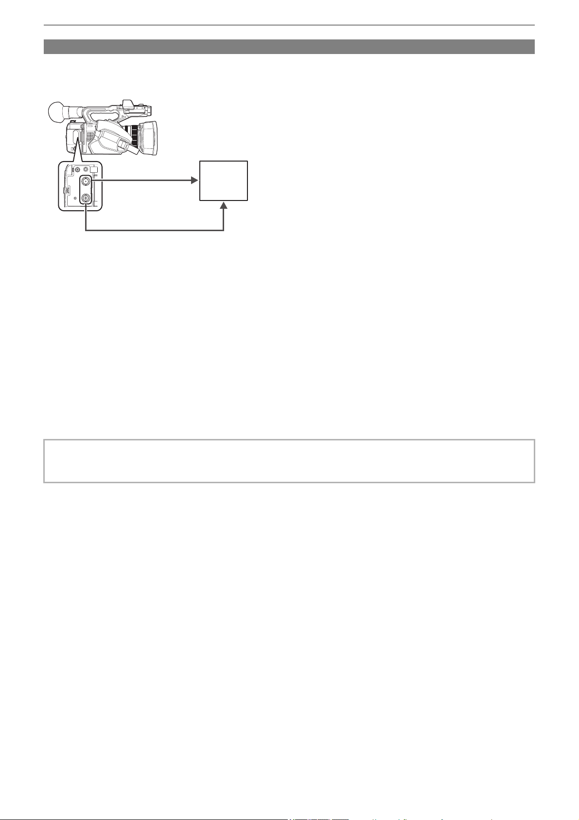
Settings before recording – Setting of time data
64
Supplying the time code externally [X2]
The time code output from the camera corresponding to the camera video or the playback video can be supplied to
an external recording device.
(A) <SDI OUT> terminal
(B) SDI IN terminal
(C) <TC IN/OUT> terminal
(D) TC IN terminal
(E) VTR, etc.
1
Select the [RECORDING] menu ¨ [TC/UB] ¨ [TC IN/OUT SEL] ¨ [TC OUT].
2
Select the [RECORDING] menu ¨ [TC/UB] ¨ [TC OUT REF] ¨ [RECORDING].
The same time code can be recorded to the video of the same time on two devices.
To match the time code output from the <TC IN/OUT> terminal to the video of the SDI
output or the monitor output
1
Select the [RECORDING] menu ¨ [TC/UB] ¨ [TC OUT REF] ¨ [SDI OUT].
• TCR is output during playback. TCG output during playback is not supported.
• The time code output may shift by 1 frame when the frame rate of [REC FORMAT] is set to 23.98p.
• Output of user bits is not supported.
(A) (B)
(C) (D)
(E)
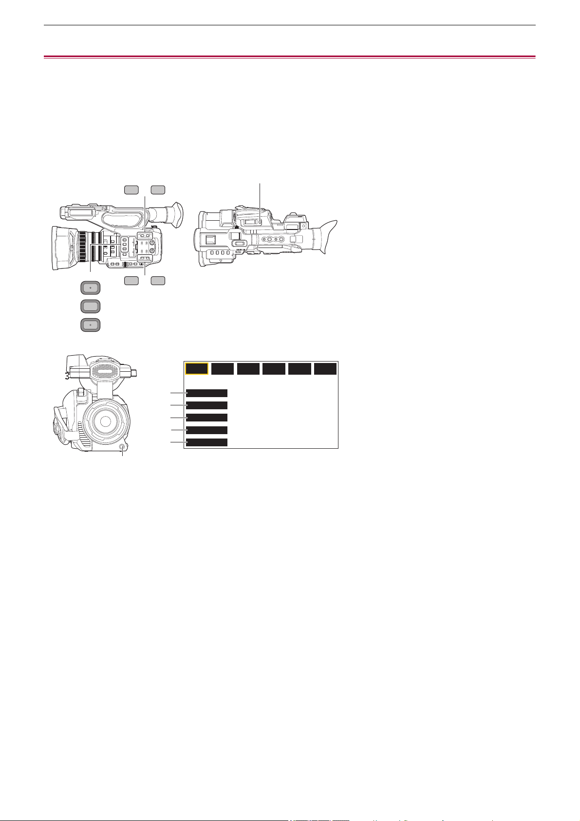
Settings before recording – Assigning functions to the USER buttons
65
Assigning functions to the USER buttons
Selected functions can be assigned to the USER buttons.
≥Functions assigned to USER buttons: 66
The USER buttons have 9 USER buttons on the unit (<USER1> to <USER9> buttons) and 5 USER button icons displayed on
the LCD monitor ([USER10] to [USER14] button icons).
The <USER1> to <USER9> buttons can be used as the USER buttons when the camera image screen is displayed.
The [USER10] to [USER14] button icons can be used as the USER buttons when the operation icon screen is displayed.
(A) <USER1> button
(B) <USER2> button
(C) <USER3> button
(D) <USER4> button
(E) <USER5> button
(F) <USER6> button
(G) <USER7> button
(H) <USER8> button
(I) <USER9> button
(J) [USER10] button icon
(K) [USER11] button icon
(L) [USER12] button icon
(M) [USER13] button icon
(N) [USER14] button icon
1
Select the function to assign to each in the [CAMERA] menu ¨ [USER SW] ¨
[USER1] to [USER14].
F1:
FOCUS MACRO
BACKLIGHT
FACE DETECT
ATW LOCK
MENU
F2:
FLUO
F3:
SPARK
F4:
STILL
F5:
CINE
F6:
HLG
(J)
(K)
(L)
(M)
(N)
(A)
USER
1
2
3
6 7
4 5
(B)
(C)
(D) (E)
(F) (G)
(H)
(I)

Settings before recording – Assigning functions to the USER buttons
66
Functions assigned to the USER buttons in the factory setting
Functions assigned to USER buttons
* Available for setting when using .
USER button/USER button icon Function (USER button icon display)
<USER1> button [AREA]
<USER2> button [AE LEVEL]
<USER3> button [SLOT SEL]
<USER4> button [WFM]
<USER5> button [ZEBRA]
<USER6> button [O.I.S.]
<USER7> button [D.ZOOM]
<USER8> button [REC CHECK]
<USER9> button [AWB]
[USER10] [FOCUS MACRO] ([FOCUS MACRO])
[USER11] [BACKLIGHT] ([BACKLIGHT])
[USER12] [FACE DETECT] ([FACE DETECT])
[USER13] [ATW LOCK] ([ATW LOCK])
[USER14] [MENU] ([MENU])
Item (USER button icon display) Description
[INHIBIT]
([INHIBIT])
Disables assignment of functions.
[AWB]
([AWB])
Assigns the automatic white balance function.
[DRS]
([DRS])
Assigns the dynamic range stretcher function.
[FBC]
([FBC])
Switches enable/disable of the flash band compensation function.
[PUSH AUTO]
([PUSH AUTO])
Assigns the one-push auto focus function.
The same is performed when the <PUSH AUTO> button is pressed.
[S.GAIN]
([S.GAIN])
Assigns the function that switches to super gain.
[AREA]
([AREA])
Assigns the area function.
[AF AREA]
([AF AREA])
Assigns the AF area width adjustment function.
[ATW]
([ATW])
Switches enable/disable of the auto tracking white balance function.
[ATW LOCK]
([ATW LOCK])
Fixes the value of the white balance. Press the USER button again or touch the USER button
icon to resume the operation of the auto tracking white balance.
Enabled when the auto tracking white balance is operating.
[SPOTLIGHT]
([SPOTLIGHT])
Switches enable/disable of the auto iris control function for the spot light.
[BACKLIGHT]
([BACKLIGHT])
Switches enable/disable of the auto iris control function for the backlight compensation.
[AE LEVEL]
([AE LEVEL])
Switches enable/disable of the AE level function.
[Y GET]
([Y GET])
Assigns the function that displays the luminance level of the frame area displayed near the
center.
[FOCUS MACRO]
([FOCUS MACRO])
Switches the focus macro setting.
[O.I.S.]
([O.I.S.])
Switches enable/disable of the optical image stabilizer function.
[O.I.S. MODE]
([O.I.S. MODE])
Switches the operation mode of the optical image stabilizer function. Each time you either
press the USER button or touch the USER button icon, the operation mode switches in the
order [NORMAL], [PAN/TILT], [STABLE]
[i.ZOOM]
([i.ZOOM])
Assigns the zoom function to minimize image distortion.
[D.ZOOM]
([D.ZOOM])
Switches enable/disable of digital zoom. Zooms in on the field angle by 2×, 5×, and 10×
vertically and horizontally each time the USER button is pressed or the USER button icon is
touched.

Settings before recording – Assigning functions to the USER buttons
67
[IR REC]
([IR REC])
Switches enable/disable of IR recording.
[FAST ZOOM]
([FAST ZOOM])
Speeds up the zoom speed when the zoom lever is pushed in all the way.
[ADAPTIVE MATRIX]
([ADAPTIVE MATRIX])
Enables/disables the function to control the linear matrix in accordance with the shooting
condition.
[REC SW]
([REC SW])
Assigns the same functions as the REC buttons.
[PRE REC]
([PRE REC])
Switches enable/disable of pre-recording.
[VFR]
([VFR])
Enables/disables the variable frame rate recording function.
[SUPER SLOW]
([SUPER SLOW])
Switches enable/disable of the super slow recording function.
[BACKGR PAUSE]
([BACKGR PAUSE])
Assigns the function that stops the background recording of card slot 2.
Press and hold the USER button to which [BACKGR PAUSE] is assigned for approximately
5 seconds or touch and hold the USER button icon for approximately 5 seconds and release
to stop background recording.
[REC CHECK]
([REC CHECK])
Automatically plays back the last approximately 3 seconds of the previously shot clip.
[DEL LAST CLIP]
([DEL LAST CLIP])
Deletes the clip last shot.
[SLOT SEL]
([SLOT SEL])
Selects the card slot for recording.
Or, switches the card slot for the clip to display in the thumbnail screen.
[AUDIO CH1 LEVEL]
([AUDIO CH1 LEVEL])
Switches the recording level adjustment method for audio channel 1 between automatic and
manual.
[AUDIO CH2 LEVEL]
([AUDIO CH2 LEVEL])
Switches the recording level adjustment method for audio channel 2 between automatic and
manual.
[FOCUS ASSIST]
([FOCUS ASSIST])
Switches enable/disable of the focus assist function.
[WFM]
([WFM])
Switches the display of the waveform monitor. The waveform display is selected in the [VIDEO
OUT/LCD/VF] menu
¨ [EI ASSIST] ¨ [WFM MODE].
[ZEBRA]
([ZEBRA])
Switches display/hide of zebra patterns.
[LEVEL GAUGE]
([LEVEL GAUGE])
Switches display/hide of the level gauge.
[LEVEL GAUGE SET]
([LEVEL GAUGE SET])
Sets the current horizontal and vertical direction as the reference value of the level gauge.
[LCD/VF OUTPUT]
*
([LCD/VF OUTPUT])
Switches the display method of the LCD monitor/viewfinder when [VIDEO OUT/LCD/VF]
menu
¨ [VIDEO OUT SEL] ¨ [SDI + HDMI OUTPUT] ¨ [ON].
[LCD/VF HDR]
*
([LCD/VF HDR])
Toggles output images from the LCD monitor and viewfinder between the high dynamic range
and standard dynamic range.
[LCD/VF V-Log]
*
([LCD/VF V-Log])
Toggles output images from the LCD monitor and viewfinder between V-Log and V-709.
[VF ON/OFF]
([VF ON/OFF])
Forces images to be displayed in the viewfinder.
[LCD/VF DETAIL]
([LCD/VF DETAIL])
Adjusts the intensity for the contour of the video in the viewfinder or LCD monitor to make it
easier to focus.
[AUDIO OUT]
([AUDIO OUT])
Switches the audio channel and the format to output from the headphone terminal and the
built-in speaker.
Each time you either press the USER button or touch the USER button icon, the audio
channel and the format switch in the order [CH1], [CH2], [CH1/2 STEREO], [CH1/2 MIX].
[FACE DETECT]
([FACE DETECT])
Switches enable/disable of the face detection AE&AF function.
[MENU]
([MENU])
Switches display/hide of the menu.
[LOAD SETUP FILE]
([LOAD SETUP FILE])
Selects the setup file saved on the memory card to load on the unit.
[LCD BACKLIGHT]
([LCD BACKLIGHT])
Switches the brightness of the LCD monitor. Each time you either press the USER button or
touch the USER button icon, the brightness switches in the order [0], [1], [2], [-1].
[CARD READER MODE]
([CARD READER MODE])
Switches enable/disable of the card reader mode function (USB mass storage function).
• Release the connection to enable the card reader mode when connected to a network via a
wireless LAN. (The unit returns to the original setting when the card reader mode is
disabled.)
[STREAMING START]
([STREAMING START])
Starts/stops streaming from the unit.
Streaming starts only during RTMP streaming.
Settings before recording – Assigning functions to the USER buttons
68
• USER button functions can also be set from the following menus:
Checking the functions assigned to the USER buttons
You can check the functions assigned to the USER buttons in the SWITCH screen of the mode check.
• For the SWITCH screen of the mode check (
ÎSWITCH screen: 259).
[DRS] [SCENE FILE] menu ¨ [DRS]
[AF AREA] [CAMERA] menu ¨ [SW MODE] ¨ [AF AREA WIDTH]
[AE LEVEL] [SCENE FILE] menu ¨ [AE LEVEL]
[FOCUS MACRO] [CAMERA] menu ¨ [SW MODE] ¨ [MACRO]
[O.I.S.] [CAMERA] menu ¨ [SW MODE] ¨ [O.I.S.]
[O.I.S. MODE] [CAMERA] menu ¨ [SW MODE] ¨ [O.I.S. MODE]
[i.ZOOM] [CAMERA] menu ¨ [SW MODE] ¨ [i.ZOOM]
[IR REC] [CAMERA] menu ¨ [SW MODE] ¨ [IR REC]
[ADAPTIVE MATRIX] [SCENE FILE] menu ¨ [MATRIX] ¨ [ADAPTIVE MATRIX]
[PRE REC] [RECORDING] menu ¨ [PRE REC]
[VFR] [SCENE FILE] menu ¨ [VFR]
[SUPER SLOW] [SYSTEM] menu ¨ [SUPER SLOW]
[AUDIO CH1 LEVEL] [AUDIO] menu ¨ [REC CH SETTINGS] ¨ [CH1 LEVEL]
[AUDIO CH2 LEVEL] [AUDIO] menu ¨ [REC CH SETTINGS] ¨ [CH2 LEVEL]
[LEVEL GAUGE] [VIDEO OUT/LCD/VF] menu ¨ [LEVEL GAUGE] ¨ [LEVEL GAUGE]
[LCD/VF OUTPUT] [VIDEO OUT/LCD/VF] menu ¨ [VIDEO OUT SEL] ¨ [LCD/VF OUTPUT]
[LCD/VF HDR] [VIDEO OUT/LCD/VF] menu ¨ [LCD/VF HDR]
[LCD/VF V-Log] [VIDEO OUT/LCD/VF] menu ¨ [LCD/VF V-Log]
[LCD/VF DETAIL] [VIDEO OUT/LCD/VF] menu ¨ [FOCUS ASSIST] ¨ [DETAIL]
[AUDIO OUT] [AUDIO] menu ¨ [OUTPUT SETTINGS] ¨ [AUDIO OUT]
[LOAD SETUP FILE] [OTHERS] menu ¨ [FILE] ¨ [SETUP FILE(SD CARD)] ¨ [LOAD]
[LCD BACKLIGHT] [VIDEO OUT/LCD/VF] menu ¨ [LCD] ¨ [BACK LIGHT]
[CARD READER MODE] [OTHERS] menu ¨ [USB DEVICE] ¨ [CARD READER MODE]
[STREAMING START] [NETWORK] menu ¨ [STREAMING] ¨ [START]
• The following functions are disabled the next time you turn the unit on after turning off the power:
– [FBC], [S.GAIN], [AREA], [ATW], [ATW LOCK], [SPOTLIGHT], [BACKLIGHT], [Y GET], [D.ZOOM], [FAST ZOOM], [REC
CHECK], [DEL LAST CLIP], [FOCUS ASSIST], [WFM], [VF ON/OFF], [CARD READER MODE], [STREAMING START]
• The following functions cannot be set when IR recording is enabled.
– [AWB], [S.GAIN], [ATW], [ATW LOCK], [SPOTLIGHT], [BACKLIGHT], [AE LEVEL], [FACE DETECT]
• In auto mode, the following functions cannot be set:
– [AWB], [FBC], [PUSH AUTO], [ATW], [FOCUS ASSIST]


Basic operation of the screen – Major button operation and screen display
70
Major button operation and screen display
1 <THUMBNAIL> button
Displays the thumbnail screen.
Playback, copy, delete, or protect of a clip can be performed.
• For details about the thumbnail screen (
ÎThumbnail operation: 224)
2 <DISP/MODE CHK> button
Press while the camera image screen is displayed to switch display/hide of most of the items.
Press the <DISP/MODE CHK> button for 1 second or more while displaying the camera image screen to display the STATUS
screen of the mode check.
Each setting and the status of the unit can be confirmed.
• For details about each screen of the mode check (
ÎMode check display: 256)
1 2
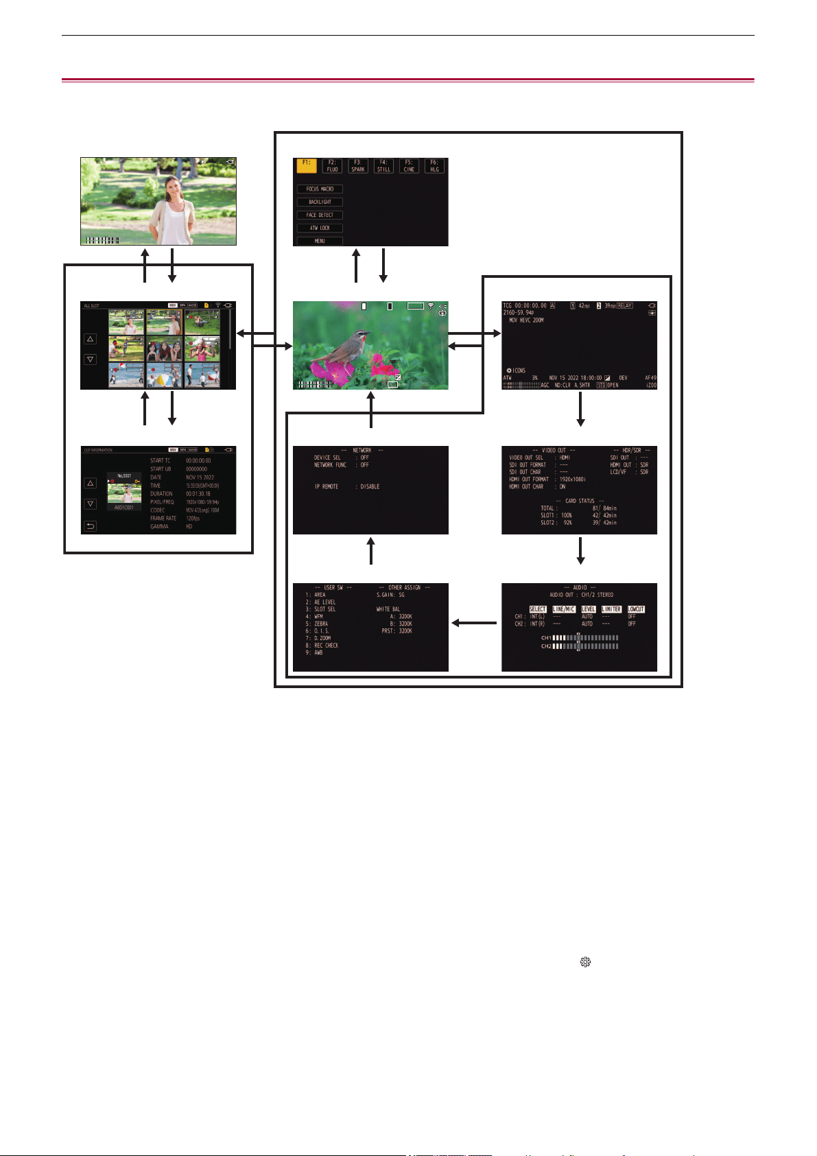
Basic operation of the screen – Major button operation and switching screen
71
Major button operation and switching screen
The screens switch as shown below when you press the <DISP/MODE CHK> button, <EXIT> button, <THUMBNAIL> button, or
multidial.
(A) Playback screen
(B) Thumbnail screen
(C) Clip information
(D) Operation icon screen
(E) Camera image screen
(F) Mode check NETWORK screen
(G) Mode check SWITCH screen
(H) Mode check STATUS screen
(I) Mode check FUNCTION screen
(J) Mode check AUDIO screen
1 Press the <DISP/MODE CHK> button.
2 Press the multidial.
3 Press the <THUMBNAIL> button.
4 Press the <EXIT> button.
5 Either touch and hold the screen for approximately 2 seconds, or press the multidial when [ ICONS] is displayed.
6 Press the <DISP/MODE CHK> button for 1 second or more.
7 Select the [THUMBNAIL] menu
¨ [CLIP] ¨ [INFORMATION].
TCR
01 : 09 : 44. 23
TCR
01 : 09 : 44. 23
ヤラヒ
ヤラビ
ヤラヒ
ヤラビ
3
34
1
6
1
1
1
1
54
47
23
TCG
01 : 09 : 42. 08
TCG
01 : 09 : 42. 08
MOV
420 150
M
MOV
420 150
M
ICONS
ICONS
ATW
ATW
AGC
AGC
ND: CLR
ND: CLR
A. SHTR
A. SHTR
ブプ
ㄎㄊㄏ
ブプ
ㄎㄊㄏ
ブプ
ㄎㄊㄏ
ブプ
ㄎㄊㄏ
ヒビ
ンユロモヺ
ンユロモヺ
ヴヵュ
ヴヵュ
ヰヱユワ
ヰヱユワ
2160 - 59. 94p
2160 - 59. 94p
ヤラヒ
ヤラビ
ヤラヒ
ヤラビ
パユヷ
パユヷ
モョパフ
モョパフ
・パパ
・パパ
フビパヒブパ
フビパヒブパ
ヶラュ ブペハペフ
ヶラュ ブペハペフ
ラユヷヤビパパ
ラユヷヤビパパ
ヶラュ ブペハペフ
ヶラュ ブペハペフ
フビパヒパパ
フビパヒパパ
ヶラュ ビペハペヘ
ヶラュ ビペハペヘ
ラユヷヤヒブパ
ラユヷヤヒブパ
ヶラュ ビペハペヘ
ヶラュ ビペハペヘ
フビビヒブパ
フビビヒブパ
ヶラュ ビペハペヘ
ヶラュ ビペハペヘ
フビパヒパパ
フビパヒパパ
ヶラュ ビピハペベ
ヶラュ ビピハペベ
ラユヷヤヒブパ
ラユヷヤヒブパ
ヶラュ ビピハペベ
ヶラュ ビピハペベ
フビビヒブパ
フビビヒブパ
ヶラュ ビピハペベ
ヶラュ ビピハペベ
フビビヒパパ
フビビヒパパ
ョラュブペハペフ
ョラュブペハペフ
0001
0001
00:00:00.00
00:00:00.00
0002
0002
00:00:16.00
00:00:16.00
0003
0003
00:00:32.15
00:00:32.15
0004
0004
00:01:00.17
00:01:00.17
0005
0005
00:01:24.02
00:01:24.02
0006
0006
00:01:46.02
00:01:46.02
0007
0007
00:02:30.20
00:02:30.20
0008
0008
00:02:53.08
00:02:53.08
0009
0009
00:03:30.20
00:03:30.20
(A) (D)
(B) (E)
(C) (F)
(G)
(H)
(I)
(J)

Basic operation of the screen – Major button operation and switching screen
72
• The camera image screen is displayed when the unit is turned on.
• The camera image screen is automatically displayed if recording starts while the thumbnail screen, playback screen or clip
information is displayed.
• The playback screen is displayed if a clip is selected in the thumbnail screen.
• The thumbnail screen is displayed if the playback of the clip ends or playback is stopped.
• The unit changes to the camera image screen if any area other than the icons in the operation icon screen is touched. The
camera image screen is displayed automatically after 5 seconds without any operation of the multidial or touch operation in
the operation icon screen.
• The camera image screen is automatically displayed after 5 seconds without operation of the <DISP/MODE CHK> button in
each screen of the mode check.
The screen will not switch to the camera image screen while the <DISP/MODE CHK> button is pressed.
• The camera image is displayed in the operation icon screen and each screen for the mode check.

Basic operation of the screen – Operating each screen
73
Operating each screen
Camera image screen
Displays the shooting screen.
• For details about the camera image screen (
ÎScreen status display: 244)
Thumbnail screen
Playback, copy, delete, or protect of a clip can be performed.
• For details about the thumbnail screen (
ÎThumbnail operation: 224)
Operation icon screen
You can select the scene file or operate the functions assigned to [USER10] through [USER14].
• For details about the operation icon screen (
ÎOperation icon screen display: 220)

74
Menu
This chapter describes how to operate the menus of the unit, menu structure, and menu details.
≥Basic operation of the menu: 75
≥[THUMBNAIL] menu: 79
≥[CAMERA] menu: 80
≥[SCENE FILE] menu: 85
≥[AUDIO] menu: 94
≥[VIDEO OUT/LCD/VF] menu: 97
≥[RECORDING] menu: 109
≥[NETWORK] menu: 112
≥[SYSTEM] menu: 120
≥[OTHERS] menu: 122
≥Factory setting value of the scene file: 126
≥Target items for scene file/setup file/initialization: 129
≥Handling setting data: 136

Menu – Basic operation of the menu
75
Basic operation of the menu
The setting of the unit can be changed with the menu in accordance to the shooting scene or recording contents.
Set data is written and saved in the main unit memory.
There are 2 methods of operation: a method to operate with the multidial, or a method to touch the LCD monitor.
≥Configuration of the menu: 75
≥Displaying the menu: 76
≥Operating the menu: 77
≥Initializing the menu: 78
Configuration of the menu
[THUMBNAIL] menu:
Performs confirmation or deleting of the recording clip.
This menu can be set when the thumbnail screen is displayed.
[CAMERA] menu:
Sets the basic functions of the camera.
This menu cannot be set when the thumbnail screen is displayed.
[SCENE FILE] menu:
Sets the setting regarding scene file.
This menu sets the detailed image quality adjustment of the camera video. Also, selection of the scene file, writing the scene file
data to the main unit memory, and loading from the main unit memory can be performed.
This menu cannot be set when the thumbnail screen is displayed.
[AUDIO] menu:
Sets the input/output function of audio.
[VIDEO OUT/LCD/VF] menu:
Configures the settings for the external output, the information to display in the LCD monitor or viewfinder and the output format.
[RECORDING] menu:
Sets the various items in the recording function.
[NETWORK] menu:
Sets the setting regarding the network function.
[SYSTEM] menu:
Configures the settings regarding the recording format of video and audio.
[OTHERS] menu:
Configures the settings for writing/loading/initializing user files to the internal memory, and the basic unit settings.
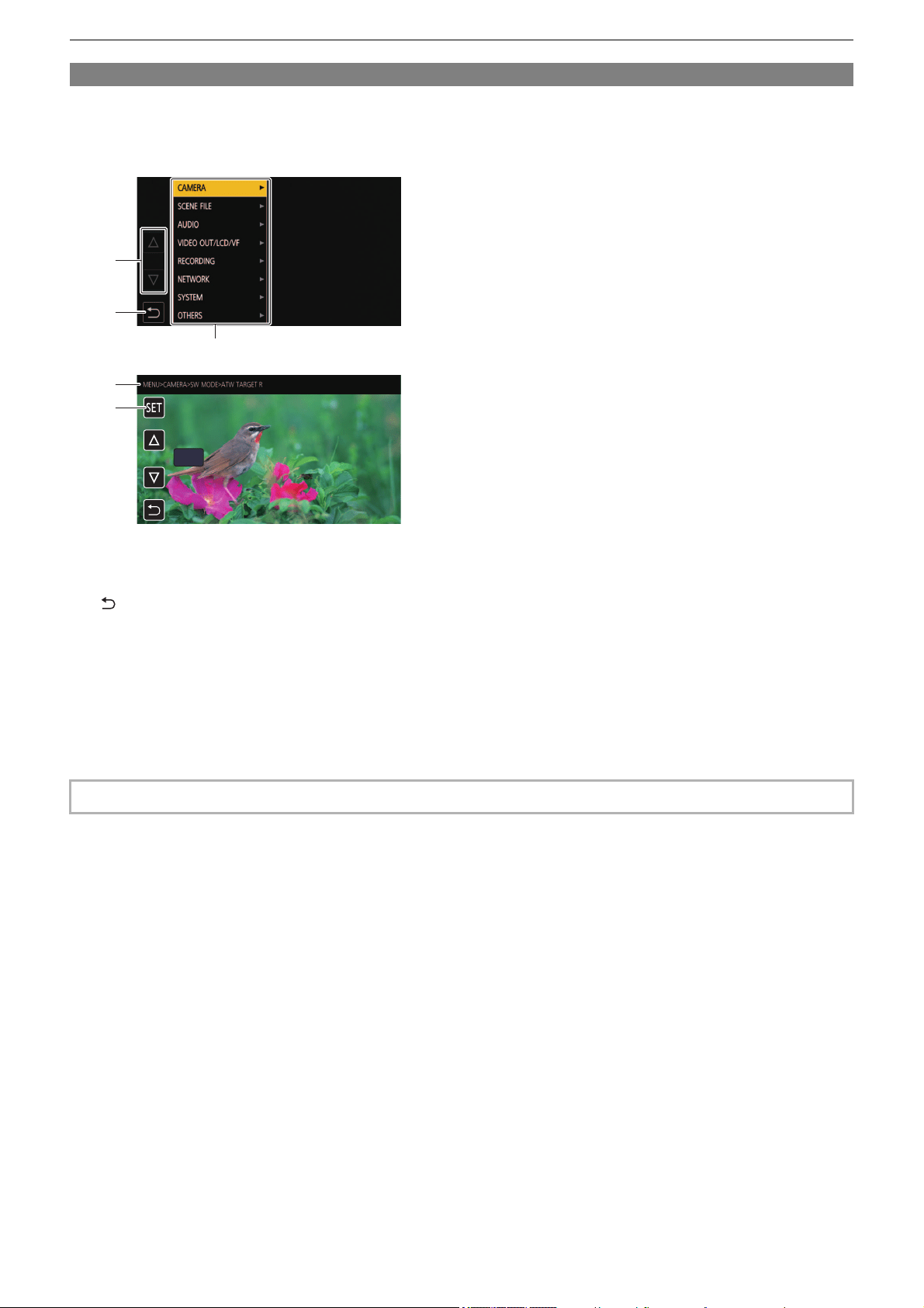
Menu – Basic operation of the menu
76
Displaying the menu
Displays the menu, and select the menu or item to set.
1
Press the <MENU> button.
The menu is displayed.
1 [#]/[$]
Switches the page or changes the value when selected.
These button icons are not available if they cannot be changed.
2 []
Returns to one level higher from the current menu when selected.
3 Menu
Moves to one level lower from the current menu, or to the setting screen when selected.
4 Level display
Displays the path of the menu to the currently displayed screen.
5 [SET]
Confirms the set value when selected.
• The menu displayed in gray characters cannot be changed.
0
4
3
5
1
2
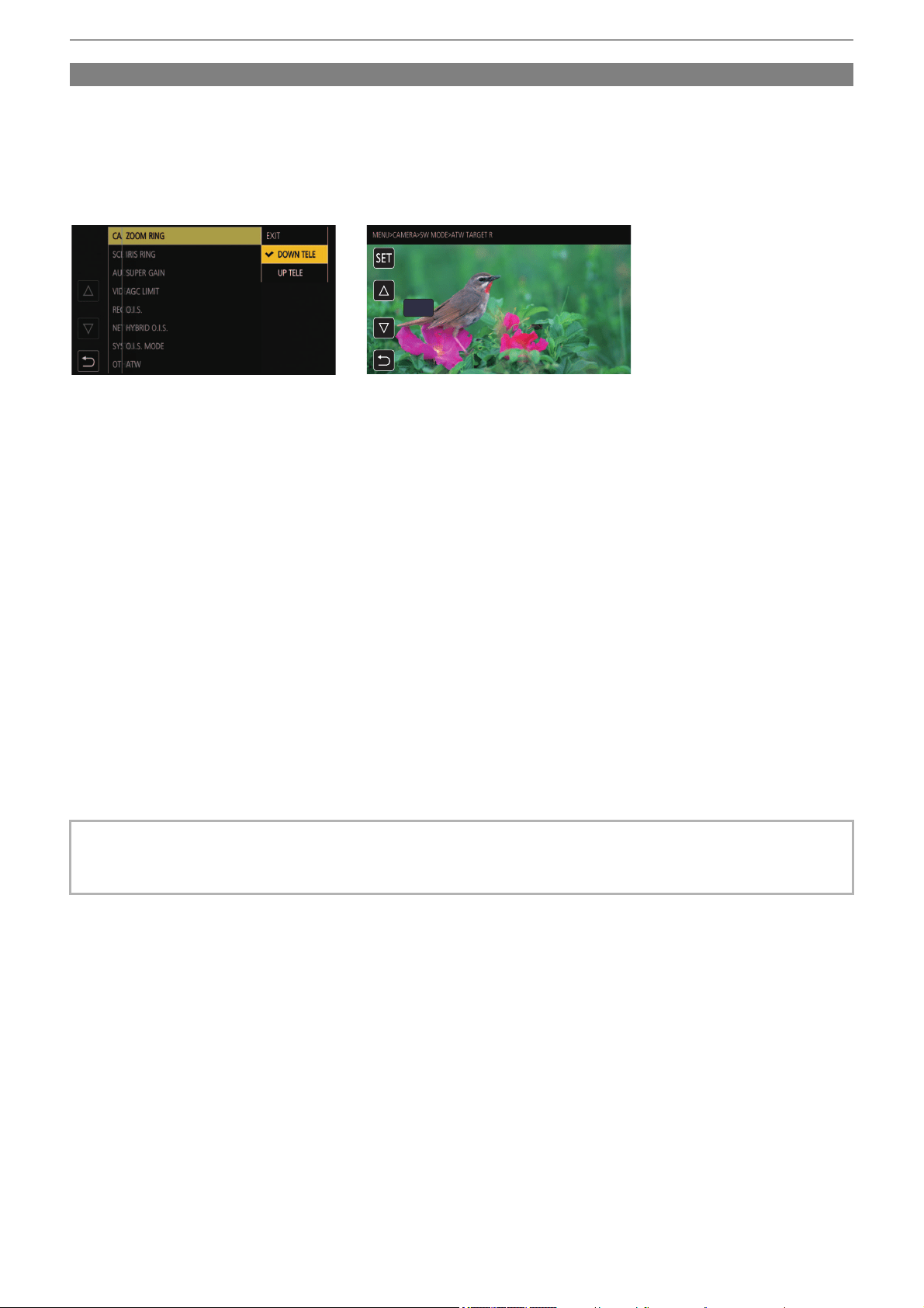
Menu – Basic operation of the menu
77
Operating the menu
Various settings are possible from the menu.
There are 2 methods of operation: a method to operate with the multidial, or a method to touch the LCD monitor.
When operating with the multidial
Operate the multidial on the main unit by turning it in vertical direction or pushing it.
1
Press the <MENU> button.
The menu is displayed.
2
Select the menu to set.
1 Turn the multidial to move the cursor to the menu to set.
2 Press the multidial.
The lower level menu is displayed.
• The confirmation screen is displayed depending on the menu.
• Perform the similar operation if there is next level.
• In some menus, a screen to set the numeric value is displayed in the camera image screen. (B)
• In some menus, a message is displayed if a menu cannot be executed.
• Press the <EXIT> button to return to one level higher.
3
Select the item to set.
1 Turn the multidial to move the cursor to the item to set.
2 Press the multidial.
A check mark is displayed at the left of the set item. (A)
• Press the <EXIT> button to return to one level higher.
4
Press the <MENU> button to close the menu.
• Depending on the operating item, it will automatically return to the previous screen.
• In screens for setting numbers (B), you can change the numbers rapidly by pressing the multidial down and holding it in the
direction you want the change to be made.
• It is also possible to select/set operation icons, thumbnail displays, etc.
(A) (B)
0
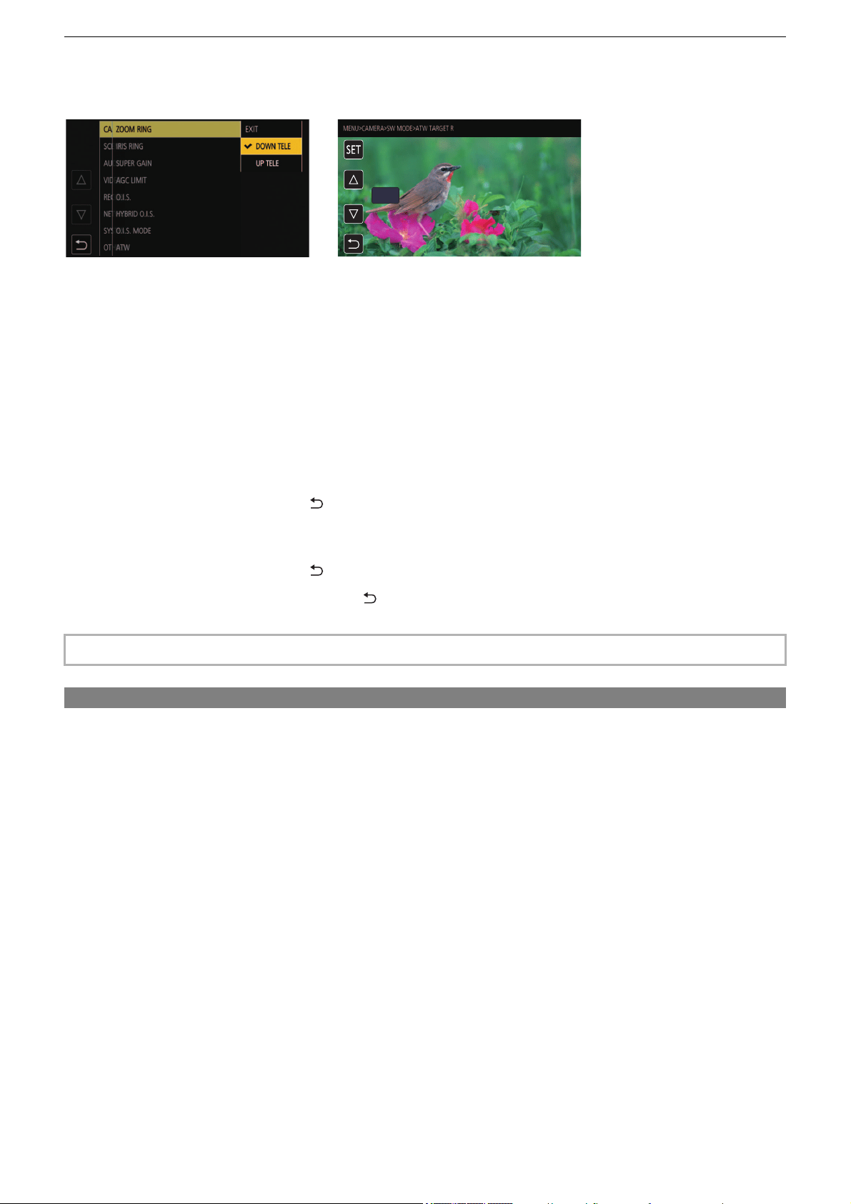
Menu – Basic operation of the menu
78
When operating by touching the LCD monitor
Operate by touching the LCD monitor.
1
Press the <MENU> button.
The menu is displayed.
2
Select the menu to set.
The lower level menu is displayed.
• The confirmation screen is displayed depending on the menu.
• Perform the similar operation if there is next level.
• In some menus, a screen to set the numeric value is displayed in the camera image screen. (B)
To change the numeric value, touch [#]/[$] and change the setting value.
• In some menus, a message is displayed if a menu cannot be executed.
• Touch [#]/[$] to switch the pages.
The button icons cannot be touched if there are no more pages.
• To return to one level higher, touch [ ].
3
Select the item to set.
• Touch the item to set. A check mark is displayed at the left of the set item. (A)
• To return to one level higher, touch [ ].
4
Exit from the menu by touching [ ], or pressing the <MENU> button.
• Depending on the operating item, it will automatically return to the previous screen.
Initializing the menu
The menu can be returned to the factory setting condition.
1
Select the [OTHERS] menu ¨ [MENU INITIALIZE].
2
Select [SET] when the confirmation message is displayed.
The setting value of the menu is returned to the factory setting.
• The values in the screen to set the numeric value (B) can be changed at high speed by touching and holding [#]/[$].
(A) (B)
0

Menu – [THUMBNAIL] menu
79
[THUMBNAIL] menu
Performs confirmation or deleting of the recording clip.
This menu can be set when the thumbnail screen is displayed.
[PLAYBACK]
Sets the playback of recorded clips.
[ALL SLOT] will always be selected when you switch from the camera image screen to the thumbnail screen.
[CLIP SEL]
Selects a clip to be displayed on the thumbnail screen.
(Factory setting: [ALL SLOT])
[RESUME PLAY]
Select if the playback is to start from the position the playback has stopped or not.
(Factory setting: [OFF])
[CLIP]
The clip can be protected or copied to a different memory card.
[DISPLAY]
Sets the display of the thumbnail screen.
[DATA]
Selects the content to be displayed in the time code display area.
(Factory setting: [START TC])
[ALL SLOT] Displays the clips recorded on all the memory cards in each card slot.
[SLOT1] Displays only the clips recorded on the memory card in card slot 1.
[SLOT2] Displays only the clips recorded on the memory card in card slot 2.
[SAME FORMAT]
Displays only the clips recorded in the same format as the system format.
Clips recorded in the same format means that each item of [FREQUENCY], [FILE FORMAT], and [REC
FORMAT] in the [SYSTEM] menu matches the current setting status.
[ON] Plays back from the position where playback has stopped.
[OFF] Always starts the playback from the beginning of the clip.
[PROTECT] [SELECT]
Protect the clip so it is not mistakenly deleted.
Select the clip to protect, and set protection.
[DELETE]
[ALL]
Deletes all the clips displayed in the thumbnail screen.
The clip that is not displayed in the thumbnail screen is not deleted.
[SELECT] Select the clip to delete, and delete it.
[COPY]
[ALL] Copies all clips to a different memory card.
[SELECT] Selects the clip to copy, and copies the clip to a different memory card.
[INFORMATION] Displays the detailed information of the clip.
• The clip recorded in MOV format/MP4 format cannot be copied.
[START TC] Displays the time code value at the start of the recording.
[CLIP NAME] Displays clip names.
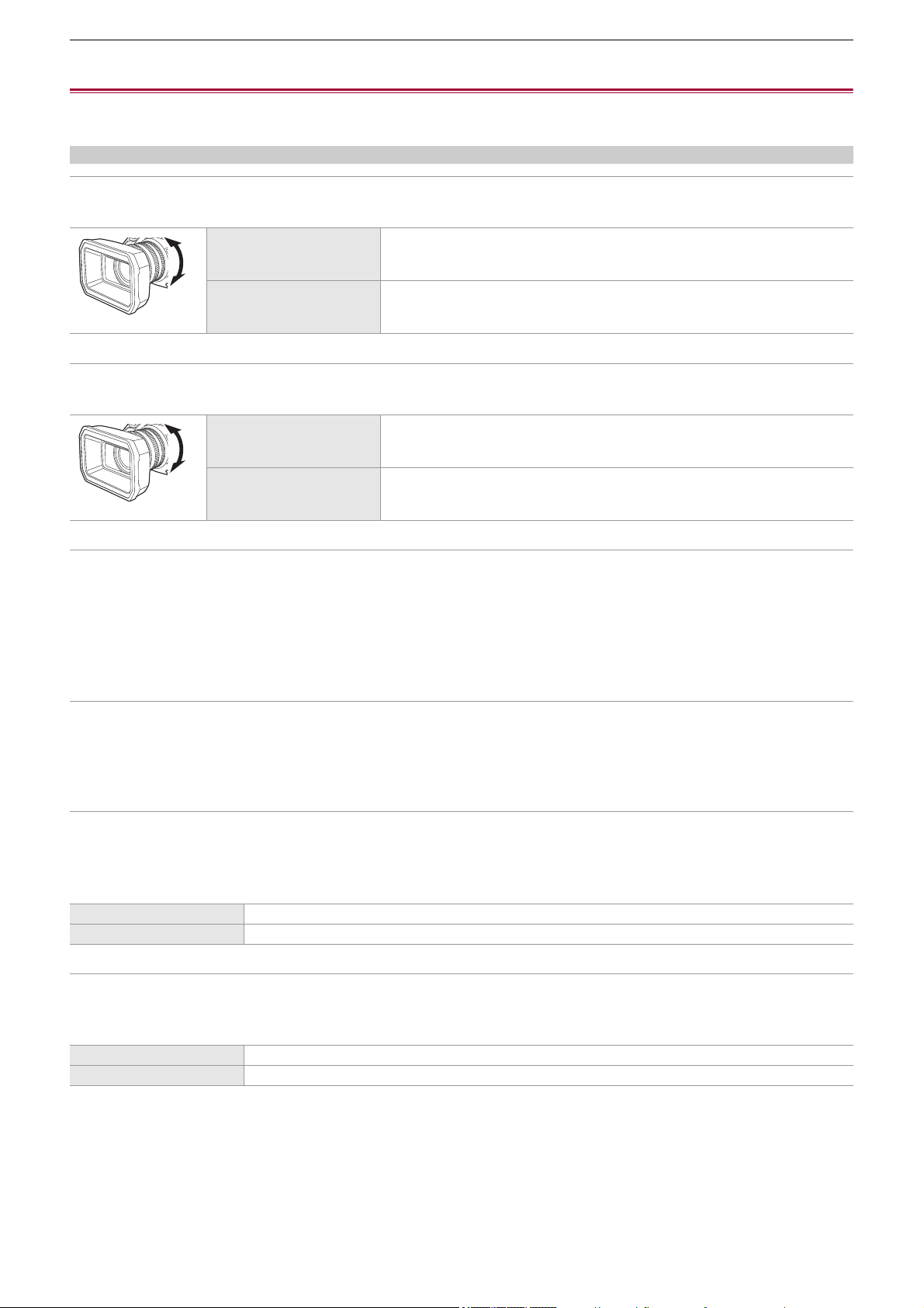
Menu – [CAMERA] menu
80
[CAMERA] menu
Sets the basic functions of the camera.
This menu cannot be set when the thumbnail screen is displayed.
[SW MODE]
[ZOOM RING]
Sets the zoom ring direction and zoom control.
(Factory setting: [DOWN TELE])
[IRIS RING]
Sets the iris ring direction and iris control.
(Factory setting: [DOWN OPEN])
[SUPER GAIN]
Sets the super gain to be assigned to the USER button.
When [ALL] is selected, each time you either press the USER button or touch the USER button icon, the selection switches in
the order [SUPER GAIN], [SUPER GAIN+], normal gain.
The items that can be set are as follows.
≥[SUPER GAIN], [SUPER GAIN+], [ALL]
(Factory setting: [SUPER GAIN])
[AGC LIMIT]
Sets the maximum gain value during [AGC] operation.
The items that can be set are as follows.
≥[3dB], [6dB], [9dB], [12dB], [15dB], [18dB], [21dB], [24dB]
(Factory setting: [24dB])
[O.I.S.]
Switches enable/disable of the optical image stabilizer function.
If [O.I.S.] is assigned to the USER button, pressing the USER button switches [ON]/[OFF].
• For details about optical image stabilizer (
ÎOptical image stabilizer function: 213)
(Factory setting: [ON])
[HYBRID O.I.S.]
Switches enable/disable of the hybrid optical image stabilizer function.
• For details about optical image stabilizer (
ÎOptical image stabilizer function: 213)
(Factory setting: [ON])
[DOWN TELE] Zooms in when turned towards the B side.
[UP TELE] Zooms in when turned towards the A side.
[DOWN OPEN] Iris opens when turned towards the B side.
[UP OPEN] Iris opens when turned towards the A side.
[ON] Enables the optical image stabilizer function.
[OFF] Disables the optical image stabilizer function.
[ON] Enables the hybrid optical image stabilizer function.
[OFF] Disables the hybrid optical image stabilizer function.
A
B
A
B
A
B
A
B

Menu – [CAMERA] menu
81
[O.I.S. MODE]
Switches the operation mode of the optical image stabilizer function.
When [O.I.S. MODE] has been assigned to a USER button, [NORMAL]/[PAN/TILT]/[STABLE] switch in order with the USER
button.
(Factory setting: [NORMAL])
[ATW]
You can set ATW (auto tracking white balance function) when the <WHITE BAL> button is pressed.
(Factory setting: [OFF])
[ATW SPEED]
Sets the control speed of the auto tracking white balance function.
The items that can be set are as follows.
≥[FAST], [NORMAL], [SLOW]
(Factory setting: [NORMAL])
[ATW TARGET R]
Make fine adjustments to the strength of red when converging with the auto tracking white balance operation.
The items that can be set are as follows.
≥[−10]…[+10]
(Factory setting: [0])
[ATW TARGET B]
Make fine adjustments to the strength of blue when converging with the auto tracking white balance operation.
The items that can be set are as follows.
≥[−10]…[+10]
(Factory setting: [0])
[W.BAL PRESET]
Sets the color temperature for when the <WHITE BAL> button is pressed to switch to "Preset".
The items that can be set are as follows.
≥[3200K], [5600K], [VAR]
(Factory setting: [3200K])
[W.BAL VAR]
Sets the value of [VAR] in [W.BAL PRESET].
The setting can also be operated by the multidial.
This is enabled when [W.BAL PRESET] is set to [VAR] and you press the <WHITE BAL> button to switch to “Preset”.
The items that can be set are as follows.
≥[2000K]…[15000K]
(Factory setting: [3200K])
[H.ZOOM SPEED]
Sets the zoom speed of the handle zoom.
The items that can be set are as follows.
≥[1]…[7]
(Factory setting: [4])
[NORMAL] Specifies the standard setting for a good balance of correction for large and small camera shake.
[PAN/TILT] Specifies a setting appropriate for shooting that uses a lot of panning and tilting of the camera.
[STABLE] Specifies a setting appropriate for fixing a composition to shoot a subject.
[Ach] If you have pressed the <WHITE BAL> button to switch to “Ach”, this is set to [ATW].
[Bch] If you have pressed the <WHITE BAL> button to switch to “Bch”, this is set to [ATW].
[PRE] If you have pressed the <WHITE BAL> button to switch to “Preset”, this is set to [ATW].
[OFF] Even if you press the <WHITE BAL> button, [ATW] does not turn on.

Menu – [CAMERA] menu
82
[i.ZOOM]
When [i.ZOOM] is set to [ON], you can zoom to a maximum of approximately 32× (24× when recording with UHD) while
maintaining the beauty of high-definition image quality.
When [i.ZOOM] has been assigned to a USER button, [ON]/[OFF] can be switched with the USER button.
(Factory setting: [ON])
[FOCUS RING DRIVE]
Switches the way focus is adjusted with the focus ring.
• Also set [FOCUS RING SETTING].
(Factory setting: [NON-LINEAR])
[FOCUS RING SETTING]
•
When [FOCUS RING DRIVE] is set to [NON-LINEAR]
Sets the way focus is adjusted with the focus ring.
(Factory setting: [SPEED])
• When [FOCUS RING DRIVE] is set to [LINEAR]
Sets the rotational angle of the focus ring.
The items that can be set are as follows.
≥[90°], [120°], [150°], [180°], [210°], [240°], [270°], [300°], [330°], [360°]
(Factory setting: [180°])
[MACRO]
Enables/disables the focus macro function.
If functions are assigned to the USER buttons, [ON]/[OFF] can be switched using the USER button operations.
(Factory setting: [OFF])
[AUTO SLOW SHTR]
You can make images brighter by making the shutter speed slower in dark places. The slow shutter works when in the auto
shutter mode.
The items that can be set are as follows.
≥[ON], [OFF]
(Factory setting: [OFF])
[ON] Enables the i.ZOOM function.
[OFF] Disables the i.ZOOM function.
[NON-LINEAR] The focus value changes according to the rotational speed and rotational position of the focus ring.
[LINEAR] The focus value changes according to the rotational angle of the focus ring.
[SPEED] Adjusts the focus value according to the speed at which the focus ring is rotated.
[COARSE]
Adjusts the focus value according to the rotational position of the focus ring.
Since the operation of the focus ring results in a greater change in focus value, this setting is suitable for
making rough adjustments.
[FINE]
Adjusts the focus value according to the rotational position of the focus ring.
Since the operation of the focus ring results in a smaller change in focus value, this setting is suitable for
making fine adjustments.
[ON] Enables the focus macro function.
[OFF] Disables the focus macro function.
• In the following case, this cannot be set.
– When using the face detection/tracking AE&AF function
• The shutter speed changes to the following depending on the frame rate of [SYSTEM] menu ¨ [REC FORMAT] and the
ambient brightness.
Frame rate of [REC FORMAT] Shutter speed
59.94p/59.94i/29.97p 1/30 or more
50.00p/50.00i/25.00p 1/25 or more
23.98p 1/24 or more
• When the shutter speed becomes 1/30, 1/25 or 1/24, the screen may be seen as if frames are missed and afterimages may
appear.

Menu – [CAMERA] menu
83
[AF SPEED]
Sets the control speed of the auto focus function.
The larger the value is, the faster the focus speed will become. Conversely, the smaller the value is, the slower the focus speed
will become.
The items that can be set are as follows.
≥[−5]…[+5]
(Factory setting: [0])
[AF SENSITIVITY]
You can enhance the stability or tracking performance of auto focus.
• Setting a larger value will enhance the tracking performance of focus, making it easier to move focus between subjects at
varying distances from this unit. We recommend that you set a larger value to keep focus on a fast-moving subject.
• Setting a smaller value will provide more stability to focus, making it easier to keep focus on the targeted subject even when
an intervening object passes in front of the camera or the subject disappears from the view of this unit. We recommend that
you set a smaller value to avoid bringing an intervening object or the background into focus.
The items that can be set are as follows.
≥[0]…[10]
(Factory setting: [5])
[AF AREA WIDTH]
You can adjust the effective area width for auto focus according to the size of the subject.
The items that can be set are as follows.
≥[ON], [OFF]
(Factory setting: [OFF])
[AREA MODE]
Assign the function that is performed within the area selected by touching the LCD monitor while shooting.
(Factory setting: [INHIBIT])
[IR REC]
Switches enable/disable of IR recording. (
ÎIR recording: 203)
The items that can be set are as follows.
≥[ON], [OFF]
(Factory setting: [OFF])
[IR REC COLOR]
Switches the color of IR recording recorded images.
The items that can be set are as follows.
≥[WHITE], [GREEN]
(Factory setting: [WHITE])
• In the following cases, this cannot be set.
– When manual focus mode is on
– When the [SCENE FILE] menu
¨ [VFR] ¨ [ON] is set
– When the [SYSTEM] menu
¨ [SUPER SLOW] ¨ [ON] is set
– When IR recording is enabled
• In the following cases, this cannot be set.
– When manual focus mode is on
– When the [SCENE FILE] menu
¨ [VFR] ¨ [ON] is set
– When the [SYSTEM] menu ¨ [SUPER SLOW] ¨ [ON] is set
– When IR recording is enabled
[INHIBIT] Disables assignment of functions.
[FOCUS] Assigns the auto focus function.
[IRIS] Assigns the auto iris function.
[Y GET] Assigns the brightness display function.
[FOCUS/IRIS] Assigns the simultaneous operation of [FOCUS] and [IRIS].
[FOCUS/Y GET] Assigns the simultaneous operation of [FOCUS] and [Y GET].
Menu – [CAMERA] menu
84
[FACE DETECT/TRACKING MODE]
Switches the behavior of focus and exposure compensation settings for the face detection/tracking AE&AF function.
(Factory setting: [FACE DETECT/TRACKING AE&AF])
[USER SW]
Sets the function to assign to the <USER1> to <USER9> buttons or the [USER10] to [USER14] button icons.
• For details about setting the USER button (
ÎAssigning functions to the USER buttons: 65)
• Following functions can be assigned to [USER1] to [USER14].
– [INHIBIT], [AWB], [DRS], [FBC], [PUSH AUTO], [S.GAIN], [AREA], [AF AREA], [ATW], [ATW LOCK], [SPOTLIGHT],
[BACKLIGHT], [AE LEVEL], [Y GET], [FOCUS MACRO], [O.I.S.], [O.I.S. MODE], [i.ZOOM], [D.ZOOM], [IR REC], [FAST
ZOOM], [ADAPTIVE MATRIX], [REC SW], [PRE REC], [VFR], [SUPER SLOW], [BACKGR PAUSE], [REC CHECK], [DEL
LAST CLIP], [SLOT SEL], [AUDIO CH1 LEVEL], [AUDIO CH2 LEVEL], [FOCUS ASSIST], [WFM], [ZEBRA], [LEVEL
GAUGE], [LEVEL GAUGE SET], [LCD/VF OUTPUT]
*
, [LCD/VF HDR]
*
, [LCD/VF V-Log]
*
, [VF ON/OFF], [LCD/VF DETAIL],
[AUDIO OUT], [FACE DETECT], [MENU], [LOAD SETUP FILE], [LCD BACKLIGHT], [CARD READER MODE],
[STREAMING START]
* Available for setting when using .
[FACE DETECT/TRACKING AF] After detecting faces, faces are tracked while auto focusing.
[FACE DETECT/TRACKING AE&AF]
After detecting faces, faces are tracked while auto focusing and automatically
adjusting exposure.
[USER1]
Sets the function to assign to the <USER1> button.
(Factory setting: [AREA])
[USER2]
Sets the function to assign to the <USER2> button.
(Factory setting: [AE LEVEL])
[USER3]
Sets the function to assign to the <USER3> button.
(Factory setting: [SLOT SEL])
[USER4]
Sets the function to assign to the <USER4> button.
(Factory setting: [WFM])
[USER5]
Sets the function to assign to the <USER5> button.
(Factory setting: [ZEBRA])
[USER6]
Sets the function to assign to the <USER6> button.
(Factory setting: [O.I.S.])
[USER7]
Sets the function to assign to the <USER7> button.
(Factory setting: [D.ZOOM])
[USER8]
Sets the function to assign to the <USER8> button.
(Factory setting: [REC CHECK])
[USER9]
Sets the function to assign to the <USER9> button.
(Factory setting: [AWB])
[USER10]
Sets the function to assign to the [USER10] button icon.
(Factory setting: [FOCUS MACRO])
[USER11]
Sets the function to assign to the [USER11] button icon.
(Factory setting: [BACKLIGHT])
[USER12]
Sets the function to assign to the [USER12] button icon.
(Factory setting: [FACE DETECT])
[USER13]
Sets the function to assign to the [USER13] button icon.
(Factory setting: [ATW LOCK])
[USER14]
Sets the function to assign to the [USER14] button icon.
(Factory setting: [MENU])

Menu – [SCENE FILE] menu
85
[SCENE FILE] menu
Sets the detailed image quality adjustment of the camera video.
This menu cannot be set when the thumbnail screen is displayed.
• For the factory settings (
ÎFactory setting value of the scene file: 126)
[FILE SELECT]
Selects the scene file (1 to 6).
You can save your favorite image settings in each scene file. Switch the scene file to suit the recording conditions.
The items that can be set are as follows.
(For the )
≥[F1:], [F2:FLUO], [F3:SPARK], [F4:STILL], [F5:CINE], [F6:HLG]
(For the )
≥[F1:], [F2:FLUO], [F3:SPARK], [F4:STILL], [F5:CINE], [F6:]
1
In the [SCENE FILE] menu ¨ [FILE SELECT] ¨ select the scene file you want to set.
• You can also select the scene file in the operation icon screen.
2
(When changing image settings)
Change the [SCENE FILE] menu settings.
You can save the following menu settings in the selected scene file. (
Î[VFR]: 86 to [AE LEVEL EFFECT]: 93):
–[VFR]
– [FRAME RATE]
– [SYNC SCAN]
– [SYNC SCAN SETTING]
– [MASTER DTL]
– [DTL CORING]
– [V.DTL LEVEL]
– [SKIN TONE DTL.]
– [SKIN DTL EFFECT]
– [RB GAIN CONTROL SETTING]
– [CHROMA LEVEL]
– [CHROMA PHASE]
–[MATRIX]
– [COLOR CORRECTION]
– [MASTER PED]
– [GAMMA MODE SEL]
– [GAMMA SETTING]
– [KNEE SETTING]
– [WHITE CLIP SETTING]
– [DRS]
– [DRS EFFECT DEPTH]
– [NR CONTROL]
– [AE LEVEL]
– [AE LEVEL EFFECT]
F1:
FOCUS MACRO
BACKLIGHT
FACE DETECT
ATW LOCK
MENU
F2:
FLUO
F3:
SPARK
F4:
STILL
F5:
CINE
F6:
HLG
Menu – [SCENE FILE] menu
86
Scene file settings at the time of purchase
(For the )
(For the )
[NAME EDIT]
Edits the name of the scene file selected in the scene file menu. (Maximum 8 characters)
• For setting procedures (
ÎChanging the scene file name: 138)
[LOAD/SAVE/INITIALIZE]
Loads/saves/initializes the setting values of the scene file assigned to the current scene file number (any one from 1 to 6).
• For setting procedures (
ÎSaving the scene file: 137, Initialization of the scene file: 138)
[VFR]
Sets enable/disable of the variable frame rate (VFR).
When [VFR] has been assigned to a USER button, [ON]/[OFF] can be switched with the USER button.
The items that can be set are as follows.
≥[ON], [OFF]
[FRAME RATE]
Switches the shooting interval and exposure time when [VFR] is [ON].
The items that can be set are as follows.
(When the [SYSTEM] menu
¨ [FREQUENCY] ¨ [59.94Hz] is set)
≥[60fps], [48fps], [45fps], [36fps], [34fps], [32fps], [30fps], [28fps], [26fps], [24fps], [22fps], [20fps], [15fps], [12fps], [2fps]
(When the [SYSTEM] menu ¨ [FREQUENCY] ¨ [50.00Hz] is set)
≥[50fps], [37fps], [30fps], [27fps], [25fps], [23fps], [21fps], [12fps], [2fps]
[SYNC SCAN]
Sets enable/disable of the synchro scan shutter.
The items that can be set are as follows.
≥[ON], [OFF]
F1: Settings suited to standard recording
F2:FLUO Settings suited to recording with consideration for fluorescent lighting (indoors, etc.)
F3:SPARK Settings suited to recordings where there is a variation in resolution, color hue, and contrast
F4:STILL You can apply a scene file with the picture tone of a digital still camera.
F5:CINE Settings suited to recordings made with an emphasis on contrast to provide a cinematic sensation
F6:HLG Settings suited to recordings made with an emphasis on the dynamic range
F1: Settings suited to standard recording
F2:FLUO Settings suited to recording with consideration for fluorescent lighting (indoors, etc.)
F3:SPARK Settings suited to recordings where there is a variation in resolution, color hue, and contrast
F4:STILL You can apply a scene file with the picture tone of a digital still camera.
F5:CINE Settings suited to recordings made with an emphasis on contrast to provide a cinematic sensation
F6: Settings suited to standard recording
• The setting at the time of purchase is [F1:].
• The operation icons disappear when you touch the screen while the operation icons are being displayed or if no touch
operations are performed for a while. To display again, touch and hold the screen for approximately 2 seconds.
[LOAD] Selects and loads the scene file saved in the internal memory of the unit.
[SAVE]
Saves the current setting value as a scene file in the internal memory of the unit by
specifying the title and the file number.
[INITIALIZE] Initializes the selected scene files (1 to 6) to the factory settings.
Menu – [SCENE FILE] menu
87
[SYNC SCAN SETTING]
Displays the speed of the synchro scan shutter that is used when shooting video for television etc.
The items that can be set are as follows.
[MASTER DTL]
Sets the level of the detail effect of the whole part.
The items that can be set are as follows.
≥[−31]…[+31]
[DTL CORING]
Sets the level of signal (including noise) that does not activate the detail effect.
The items that can be set are as follows.
≥[0]…[61]
[V.DTL LEVEL]
Sets the intensity of the detail level in the vertical direction.
The items that can be set are as follows.
≥[−7]…[+7]
[SKIN TONE DTL.]
The skin of human subjects can be made to appear smoother when recorded.
The items that can be set are as follows.
≥[ON], [OFF]
[SKIN DTL EFFECT]
Sets the effective level of the skin tone detail.
The items that can be set are as follows.
≥[0]…[31]
Frame rate of the recording format Setting value
59.94p/59.94i [1/60.0]…[1/249.6]
29.97p [1/30.0]…[1/249.8]
23.98p [1/24.0]…[1/249.7]
50.00p/50.00i [1/50.0]…[1/250.0]
25.00p [1/25.0]…[1/250.0]
• This can be set when all of the following conditions are fulfilled:
– When the <AUTO/MANU> switch is set to <MANU>
– When the manual shutter mode is set
– When the [SCENE FILE] menu
¨ [SYNC SCAN] ¨ [ON] is set
– Flash band compensation function is disabled
• If the background or anything else in the scene has colors similar to the skin color, they will also be smoothed.
• If the brightness is insufficient, the effect may not be clear.
• If you record a person in the distance, the face may not be recorded clearly. In this case, set [SKIN TONE DTL.] to [OFF] or
zoom in on the face (close-up) to record.

Menu – [SCENE FILE] menu
88
[RB GAIN CONTROL SETTING]
Adjust the color hue when white balance has been set in “Preset”, “Ach” or “Bch”.
You can also decide whether to maintain the setting content when you have made white balance adjustments/black balance
adjustments.
[R GAIN AWB PRE]
Set the Rch gain (strength of red) for white balance “Preset”.
The items that can be set are as follows.
≥[−200]…[+200]
[B GAIN AWB PRE]
Set the Bch gain (strength of blue) for white balance “Preset”.
The items that can be set are as follows.
≥[−200]…[+200]
[R GAIN AWB A]
Set the Rch gain (strength of red) for white balance “Ach”.
The items that can be set are as follows.
≥[−200]…[+200]
[B GAIN AWB A]
Set the Bch gain (strength of blue) for white balance “Ach”.
The items that can be set are as follows.
≥[−200]…[+200]
[R GAIN AWB B]
Set the Rch gain (strength of red) for white balance “Bch”.
The items that can be set are as follows.
≥[−200]…[+200]
[B GAIN AWB B]
Set the Bch gain (strength of blue) for white balance “Bch”.
The items that can be set are as follows.
≥[−200]…[+200]
[AWB A GAIN OFFSET]
When the white balance has been automatically performed with “Ach”, set the value of Rch gain and Bch gain.
[AWB B GAIN OFFSET]
When the white balance has been automatically performed with “Bch”, set the value of Rch gain and Bch gain.
[CHROMA LEVEL]
Sets the chroma level of and signals.
The items that can be set are as follows.
≥[−99%]…[+99%], [OFF]
[CHROMA PHASE]
Finely adjusts the chroma phase of the signal and signal.
The items that can be set are as follows.
≥[−31]…[+31]
[ON] Keeps the values set in [R GAIN AWB A] and [B GAIN AWB A].
[OFF] Sets the value of Rch gain and Bch gain to [0].
[ON] Keeps the values set in [R GAIN AWB B] and [B GAIN AWB B].
[OFF] Sets the value of Rch gain and Bch gain to [0].
P
R
P
B
P
R
P
B

Menu – [SCENE FILE] menu
89
[MATRIX]
[MATRIX TYPE]
Selects the matrix table to display the color for shooting.
[ADAPTIVE MATRIX]
Enables/disables the function to control the linear matrix in accordance with the shooting condition.
When [ADAPTIVE MATRIX] has been assigned to a USER button, [ON]/[OFF] can be switched with the USER button.
The items that can be set are as follows.
≥[ON], [OFF]
[COLOR CORRECTION]
Sets the saturation and phase for colors. Each of the 16 divisions of color hue can be set individually.
[R]
The items that can be set are as follows.
≥[−63]…[+63]
[R-R-Mg]
The items that can be set are as follows.
≥[−63]…[+63]
[R-Mg]
The items that can be set are as follows.
≥[−63]…[+63]
[Mg]
The items that can be set are as follows.
≥[−63]…[+63]
[Mg-B]
The items that can be set are as follows.
≥[−63]…[+63]
[B]
The items that can be set are as follows.
≥[−63]…[+63]
[NORMAL1] Displays the color suitable for shooting outdoors or under a halogen lamp.
[NORMAL2] Displays more vivid color than [NORMAL1].
[FLUO.] Displays the color suitable for shooting indoors under fluorescent light.
[CINELIKE] Displays the color suitable for shooting cinematic video.
[STILL LIKE] Expresses colors in a picture tone similar to that produced with a digital still camera.
[SAT] Corrects red color saturation.
[PHASE] Corrects the red hue.
[SAT] Corrects the color saturation between red and the color which is intermediate between red and magenta.
[PHASE] Corrects the hue between red and the color which is intermediate between red and magenta.
[SAT] Corrects the color saturation between red and magenta.
[PHASE] Corrects the hue between red and magenta.
[SAT] Corrects magenta color saturation.
[PHASE] Corrects the magenta hue.
[SAT] Corrects the color saturation between magenta and blue.
[PHASE] Corrects the hue between magenta and blue.
[SAT] Corrects blue color saturation.
[PHASE] Corrects the blue hue.

Menu – [SCENE FILE] menu
90
[B-Cy]
The items that can be set are as follows.
≥[−63]…[+63]
[Cy]
The items that can be set are as follows.
≥[−63]…[+63]
[Cy-G]
The items that can be set are as follows.
≥[−63]…[+63]
[G]
The items that can be set are as follows.
≥[−63]…[+63]
[G-Yl]
The items that can be set are as follows.
≥[−63]…[+63]
[G-Yl-Yl]
The items that can be set are as follows.
≥[−63]…[+63]
[Yl]
The items that can be set are as follows.
≥[−63]…[+63]
[Yl-Yl-R]
The items that can be set are as follows.
≥[−63]…[+63]
[Yl-R]
The items that can be set are as follows.
≥[−63]…[+63]
[SAT] Corrects the color saturation between blue and cyan.
[PHASE] Corrects the hue between blue and cyan.
[SAT] Corrects cyan color saturation.
[PHASE] Corrects the cyan hue.
[SAT] Corrects the color saturation between cyan and green.
[PHASE] Corrects the hue between cyan and green.
[SAT] Corrects green color saturation.
[PHASE] Corrects the green hue.
[SAT] Corrects the color saturation between green and yellow.
[PHASE] Corrects the hue between green and yellow.
[SAT] Corrects the color saturation between yellow and the color which is intermediate between green and yellow.
[PHASE] Corrects the hue between yellow and the color which is intermediate between green and yellow.
[SAT] Corrects yellow color saturation.
[PHASE] Corrects the yellow hue.
[SAT] Corrects the color saturation between yellow and the color which is intermediate between yellow and red.
[PHASE] Corrects the hue between yellow and the color which is intermediate between yellow and red.
[SAT] Corrects the color saturation between yellow and red.
[PHASE] Corrects the hue between yellow and red.
Menu – [SCENE FILE] menu
91
[Yl-R-R]
The items that can be set are as follows.
≥[−63]…[+63]
[MASTER PED]
Sets the master pedestal.
The items that can be set are as follows.
≥[−200]…[+200]
[GAMMA MODE SEL]
Selects the gamma mode.
* Available for setting when using .
[GAMMA SETTING]
[BLACK GAMMA]
Sets the gamma curves of dark areas.
[SAT] Corrects the color saturation between red and the color which is intermediate between yellow and red.
[PHASE] Corrects the hue between red and the color which is intermediate between yellow and red.
[HD] Sets the gamma characteristics for HD (High Definition).
[SD] Increases gain in darker areas more than HD gamma.
[FILMLIKE1] Sets the characteristics that reproduce more highlight areas compared to HD gamma.
[FILMLIKE2]
Sets the characteristics that reproduce more highlight areas compared to
[FILMLIKE1].
[FILMLIKE3]
Sets the characteristics that reproduce more highlight areas compared to
[FILMLIKE2].
[CINE-LIKE D]
Sets gamma characteristics to produce images with an emphasis on contrast to
provide a cinematic sensation.
[CINE-LIKE V] Sets gamma characteristics to produce images that provide a cinematic sensation.
[STILL LIKE] Sets the gamma characteristics for a digital still camera image tone.
[HLG]
*
Sets the hybrid log gamma (HLG) characteristics.
[V-Log]
*
Sets the gamma curve that is a prerequisite for post production processes.
(For the )
• The following menus cannot be set when [HLG] is set.
– [SCENE FILE] menu
¨ [KNEE SETTING] ¨ [KNEE MODE]/[KNEE POINT]/[KNEE SLOPE]
– [SCENE FILE] menu
¨ [WHITE CLIP SETTING]/[DRS]/[DRS EFFECT DEPTH]
– [VIDEO OUT/LCD/VF] menu
¨ [SDI SETTING] ¨ [SDI OUT ZEBRA]
– [VIDEO OUT/LCD/VF] menu
¨ [HDMI SETTING] ¨ [HDMI OUT ZEBRA]
– [VIDEO OUT/LCD/VF] menu ¨ [EI ASSIST] ¨ [ZEBRA]/[ZEBRA1 DETECT]/[ZEBRA2 DETECT]/[ZEBRA2]
• The following menus cannot be set when [V-Log] is set.
– [CAMERA] menu
¨ [SW MODE] ¨ [IR REC]
– [SCENE FILE] menu
¨ [MASTER DTL]/[DTL CORING]/[V.DTL LEVEL]/[SKIN TONE DTL.]/[SKIN DTL EFFECT]/
[CHROMA LEVEL]/[CHROMA PHASE]/[MATRIX]/[COLOR CORRECTION]/[MASTER PED]/[GAMMA SETTING]/[KNEE
SETTING]/[WHITE CLIP SETTING]/[DRS]/[DRS EFFECT DEPTH]
– [VIDEO OUT/LCD/VF] menu ¨ [SDI SETTING] ¨ [SDI OUT ZEBRA]
– [VIDEO OUT/LCD/VF] menu
¨ [HDMI SETTING] ¨ [HDMI OUT ZEBRA]
– [VIDEO OUT/LCD/VF] menu
¨ [EI ASSIST] ¨ [ZEBRA]/[ZEBRA1 DETECT]/[ZEBRA2 DETECT]/[ZEBRA2]
[−8]…[−1] Compresses dark parts.
[0] Standard state
[+1]…[+8] Expands dark areas.
Menu – [SCENE FILE] menu
92
[B.GAMMA RANGE]
Sets the maximum level of compression/expansion.
[KNEE SETTING]
[KNEE MODE]
To avoid overexposure, select the compression level of the high intensity video signals received through the image sensor.
[KNEE POINT]
Sets the knee point position in 0.5 % steps.
The items that can be set are as follows.
≥[70.0%]…[107.0%]
[KNEE SLOPE]
Sets the knee inclination.
The items that can be set are as follows.
≥[0]…[99]
[HLG KNEE SW]
Enables/disables the operation of knee for HLG.
The items that can be set are as follows.
≥[ON], [OFF]
[HLG KNEE POINT]
Sets the position of the knee point for HLG.
The items that can be set are as follows.
≥[55]…[100]
[HLG KNEE SLOPE]
Sets the inclination of knee for HLG.
The items that can be set are as follows.
≥[0]…[100]
[WHITE CLIP SETTING]
Sets so that the brightest parts of the video signal cannot exceed a certain level.
[WHITE CLIP]
Switches the white clip function [ON]/[OFF]. The [WHITE CLIP LEVEL] setting value is enabled when [ON].
The items that can be set are as follows.
≥[ON], [OFF]
[WHITE CLIP LEVEL]
Sets the white clip level.
The items that can be set are as follows.
≥[90%]…[109%]
[1] Around 20 %
[2] Around 30 %
[3] Around 40 %
[AUTO] Sets up automatically depending on the signal from the image sensor.
[MANUAL] The [KNEE POINT], [KNEE SLOPE] settings are applied.
[OFF] Disables the Knee function.
• Can be set when [SCENE FILE] menu ¨ [GAMMA MODE SEL] is set to [HLG].
• Can be set when [SCENE FILE] menu
¨ [GAMMA MODE SEL] is set to [HLG].
• Can be set when [SCENE FILE] menu
¨ [GAMMA MODE SEL] is set to [HLG].
Menu – [SCENE FILE] menu
93
[DRS]
Switches enable/disable of the dynamic range stretcher function.
If the function is assigned to a USER button, [ON]/[OFF] can be switched by operating the USER button.
The items that can be set are as follows.
≥[ON], [OFF]
[DRS EFFECT DEPTH]
Sets the compression level of the high luminosity areas of the dynamic range stretcher function.
By compressing the video signal levels of the high luminosity areas that are blown out in normal shooting, the dynamic range
can be expanded.
The items that can be set are as follows.
≥[1]…[3]
[NR CONTROL]
You can adjust the effect of noise reduction and afterimages by changing the noise reduction settings.
[AE LEVEL]
Switches enable/disable of the AE level function.
If the function is assigned to a USER button, [ON]/[OFF] can be switched by operating the USER button.
The items that can be set are as follows.
≥[ON], [OFF]
[AE LEVEL EFFECT]
When AE level is enabled, you can set the exposure compensation value.
Set to the “+” direction to brighten and set to the “−” direction to darken.
The items that can be set are as follows.
≥[−2.0EV]…[+2.0EV]
• As the number increases, the compression level of high luminosity areas increases, and there will be more noise in dark
areas.
[−7]…[−1] Weakens the effect of noise reduction, reducing afterimages. There will tend to be more noise.
[0] Standard state
[+1]…[+7]
Strengthens the effect of noise reduction, reducing noise. However, this may result in an increase in
afterimages.
• In the following cases, this cannot be set.
– When all of iris, gain, and shutter speed are set to manual in the manual mode
– When IR recording is enabled
• In the following cases, this cannot be set.
– When all of iris, gain, and shutter speed are set to manual in the manual mode
– When IR recording is enabled

Menu – [AUDIO] menu
94
[AUDIO] menu
Sets the input/output function of audio.
[INPUT SETTINGS]
[INPUT1 MIC LEVEL]
Sets the input level of the external microphone connected to the <AUDIO INPUT1> terminal. Enabled when the external
microphone is connected and the <INPUT 1> switch is set to <MIC> or <i48V>.
The items that can be set are as follows.
≥[j40dB], [j50dB], [j60dB]
(Factory setting: [j50dB])
[INPUT2 MIC LEVEL]
Sets the input level of the external microphone connected to the <AUDIO INPUT2> terminal. Enabled when the external
microphone is connected and the <INPUT 2> switch is set to <MIC> or <i48V>.
The items that can be set are as follows.
≥[j40dB], [j50dB], [j60dB]
(Factory setting: [j50dB])
[INPUT1 LINE LEVEL]
Sets the audio input level of the audio device connected to the <AUDIO INPUT1> terminal. Enabled when the audio device is
connected and the <INPUT 1> switch is set to <LINE>.
The items that can be set are as follows.
≥[4dB], [0dB]
(Factory setting: [0dB])
[INPUT2 LINE LEVEL]
Sets the audio input level of the audio device connected to the <AUDIO INPUT2> terminal. Enabled when the audio device is
connected and the <INPUT 2> switch is set to <LINE>.
The items that can be set are as follows.
≥[4dB], [0dB]
(Factory setting: [0dB])
[REC CH SETTINGS]
[CH1 LEVEL]
Sets if the recording level adjustment method for audio channel 1 is to be automatic or manual.
If [AUDIO CH1 LEVEL] is assigned to a USER button, [AUTO]/[MANUAL] can be switched by operating the USER button.
The items that can be set are as follows.
≥[AUTO], [MANUAL]
(Factory setting: [AUTO])
[CH2 LEVEL]
Sets if the recording level adjustment method for audio channel 2 is to be automatic or manual.
If [AUDIO CH2 LEVEL] is assigned to a USER button, [AUTO]/[MANUAL] can be switched by operating the USER button.
The items that can be set are as follows.
≥[AUTO], [MANUAL]
(Factory setting: [AUTO])
[CH1 MIC LOWCUT]
Switches enable/disable of the lowcut filter for audio channel 1.
The items that can be set are as follows.
≥[ON], [OFF]
(Factory setting: [OFF])
[CH2 MIC LOWCUT]
Switches enable/disable of the lowcut filter for audio channel 2.
The items that can be set are as follows.
≥[ON], [OFF]
(Factory setting: [OFF])

Menu – [AUDIO] menu
95
[CH1 LIMITER]
Switches enable/disable of the limiter when the method to adjust the audio input level for audio channel 1 is manual.
The items that can be set are as follows.
≥[ON], [OFF]
(Factory setting: [OFF])
[CH2 LIMITER]
Switches enable/disable of the limiter when the method to adjust the audio input level for audio channel 2 is manual.
The items that can be set are as follows.
≥[ON], [OFF]
(Factory setting: [OFF])
[MIC LIMITER LINK]
Sets whether to make the limiter work on the other audio channel when the limiter works in either audio channel 1 or audio
channel 2.
The items that can be set are as follows.
≥[ON], [OFF]
(Factory setting: [OFF])
[HEAD ROOM]
Sets the headroom (standard level).
The items that can be set are as follows.
≥[12dB], [18dB], [20dB]
Default setting specifications vary depending on the country or area where the camera was purchased.
[OUTPUT SETTINGS]
[AUDIO OUT]
Sets the audio channel and the format to output from the headphone terminal, and the built-in speaker.
When [AUDIO OUT] has been assigned to a USER button, [CH1]/[CH2]/[CH1/2 STEREO]/[CH1/2 MIX] switch in order with the
USER button.
(Factory setting: [CH1/2 STEREO])
[ALARM]
Sets whether to have an alarm sound.
The alarm is output from the speaker of this unit or the headphones. It is not output to external output destinations.
[BATTERY END]
Sets whether to sound the alarm when the remaining battery level is exhausted.
The items that can be set are as follows.
≥[HIGH], [LOW], [OFF]
(Factory setting: [OFF])
• In the following case, [CH1 LIMITER] is fixed to [ON]:
– When [CH1 LEVEL] is set to [AUTO]
• In the following case, [CH2 LIMITER] is fixed to [ON]:
– When [CH2 LEVEL] is set to [AUTO]
• In the following case, [MIC LIMITER LINK] is fixed to [OFF]:
– When the [CH1 LIMITER] or [CH2 LIMITER] is set to [OFF]
[CH1] Outputs the signal for audio channel 1 as monaural.
[CH2] Outputs the signal for audio channel 2 as monaural.
[CH1/2 STEREO]
Outputs the signals of the audio channel 1 and the audio channel 2 as stereo. Outputs as monaural from the
built-in speaker.
[CH1/2 MIX] Mixes the signals of the audio channel 1 and the audio channel 2 and outputs as monaural.

Menu – [AUDIO] menu
96
[MEDIA END]
Sets whether to sound the alarm when the remaining recording capacity of the memory card is exhausted.
The items that can be set are as follows.
≥[HIGH], [LOW], [OFF]
(Factory setting: [OFF])
[WARNING]
Sets whether to sound the alarm when a system error or warning occurs.
The items that can be set are as follows.
≥[HIGH], [LOW], [OFF]
(Factory setting: [OFF])
Menu – [VIDEO OUT/LCD/VF] menu
97
[VIDEO OUT/LCD/VF] menu
Configures the settings for the external output, the information to display in the LCD monitor or viewfinder and the output format.
[VIDEO OUT SEL]
[SDI + HDMI OUTPUT]
Switches whether simultaneous output for the <SDI OUT> terminal and <HDMI> terminal is enabled or disabled.
(Factory setting: [OFF])
[EXTERNAL OUT SEL]
Switches the output destination for images and audio. Can be set when [SDI + HDMI OUTPUT] is set to [OFF].
(Factory setting: [HDMI])
[SDI OUT FORMAT]
Selects the signal to output from the <SDI OUT> terminal. The items that can be selected differ depending on the [SYSTEM]
menu
¨ [FREQUENCY]/[FILE FORMAT]/[REC FORMAT] setting.
(Factory setting: [1920×1080i])
[HDMI OUT FORMAT]
Selects the signal to output from the <HDMI> terminal. The items that can be selected differ depending on the [SYSTEM] menu
¨ [FREQUENCY]/[FILE FORMAT]/[REC FORMAT] setting.
(Factory setting: [1920×1080p])
[LCD/VF OUTPUT]
Sets the display method of the LCD monitor/viewfinder. Can be set when [SDI + HDMI OUTPUT] is set to [ON].
The items that can be set are as follows.
≥[AUTO], [LCD]
(Factory setting: [AUTO])
[ON] Signal is output from both the <SDI OUT> terminal and the <HDMI> terminal.
[OFF] Signal set in [VIDEO OUT/LCD/VF] menu ¨ [VIDEO OUT SEL] ¨ [EXTERNAL OUT SEL] is output.
[SDI] Outputs from the <SDI OUT> terminal.
[HDMI] Outputs from the <HDMI> terminal.
[1920×1080p] Outputs in 1920×1080p.
[1920×1080i] Outputs in 1920×1080i.
[1920×1080PsF] Outputs in 1920×1080PsF.
[1280×720p] Outputs in 1280×720p.
• For the combinations that can be set (ÎFormat that can be output from the SDI OUT terminal [X2]: 239)
[3840×2160p] Outputs in 3840×2160p (4:2:2/10 bit).
[3840×2160p(420/8bit)] Outputs in 3840×2160p (4:2:0/8 bit).
[1920×1080p] Outputs in 1920×1080p.
[1920×1080i] Outputs in 1920×1080i.
[1280×720p] Outputs in 1280×720p.
[720×480p] Outputs in 720×480p.
[720×576p] Outputs in 720×576p.
• For the combinations that can be set (
ÎFormat that can be output from the HDMI terminal: 240)
Menu – [VIDEO OUT/LCD/VF] menu
98
[SDI SETTING]
[SDI REC REMOTE]
Sets if the recording operation against the external equipment connected to the <SDI OUT> terminal (such as recorder) is to be
controlled or not.
(Factory setting: [OFF])
[SDI OUT CHAR]
Sets whether to superimpose the character to the output from the <SDI OUT> terminal.
(Factory setting: [OFF])
[SDI OUT ZEBRA]
Sets whether to superimpose the zebra signal to the output from the <SDI OUT> terminal. The settings of the zebra signal follow
the zebra signal settings in the [VIDEO OUT/LCD/VF] menu
¨ [EI ASSIST].
(Factory setting: [OFF])
[SDI OUT HDR]
Sets the output image from the <SDI OUT> terminal when the [SCENE FILE] menu
¨ [GAMMA MODE SEL] is set to [HLG].
(Factory setting: [HDR])
[SDI OUT V-Log]
Sets the output image from the <SDI OUT> terminal when the [SCENE FILE] menu
¨ [GAMMA MODE SEL] is set to [V-Log].
(Factory setting: [V-Log])
[ON] Controls the recording operation of the external equipment.
[OFF] Does not control the recording operation of the external equipment.
• This cannot be set when the [RECORDING] menu
¨ [REC FUNCTION] ¨ [REC MODE] is set to [INTERVAL].
• The AUTO REC signal is compatible with TYPE3 when remotely recording with SDI.
• When all of the following menu settings have been made, it is possible to control recording by external devices connected to
the <SDI OUT> terminal and the <HDMI> terminal.
– [VIDEO OUT/LCD/VF] menu
¨ [VIDEO OUT SEL] ¨ [SDI + HDMI OUTPUT] ¨ [ON]
– [VIDEO OUT/LCD/VF] menu
¨ [SDI SETTING] ¨ [SDI REC REMOTE] ¨ [ON]
– [VIDEO OUT/LCD/VF] menu
¨ [HDMI SETTING] ¨ [HDMI TC OUT] ¨ [ON]
– [VIDEO OUT/LCD/VF] menu
¨ [HDMI SETTING] ¨ [HDMI REC REMOTE] ¨ [ON]
[ON] Superimposes.
[OFF] Does not superimpose.
[ON] Superimposes.
[OFF] Does not superimpose.
[SDR] Outputs in the standard dynamic range.
[HDR] Outputs in the high dynamic range.
[V-Log] Outputs in same color as the recording image.
[V-709] Outputs in a converted color equivalent to standard CINE-LIKE. Setting suitable for a preview.
Menu – [VIDEO OUT/LCD/VF] menu
99
[HDMI SETTING] / [HDMI OUT]
[OUT FORMAT]
Selects the signal to output from the <HDMI> terminal. The items that can be selected differ depending on the [SYSTEM] menu
¨ [FREQUENCY]/[FILE FORMAT]/[REC FORMAT] setting.
(Factory setting: [1920×1080p])
[HDMI TC OUT]
Sets whether time code information is output from the <HDMI> terminal.
The items that can be set are as follows.
≥[ON], [OFF]
(Factory setting: [OFF])
[HDMI REC REMOTE]
Sets if the recording operation against the external equipment connected to the <HDMI> terminal (such as recorder) is to be
controlled or not. This can be set when [HDMI TC OUT] is enabled.
(Factory setting: [OFF])
[HDMI OUT CHAR]
Sets whether to superimpose the character to the output from the <HDMI> terminal.
(Factory setting: [OFF])
[HDMI OUT ZEBRA]
Sets whether to superimpose the zebra signal to the output from the <HDMI> terminal. The settings of the zebra signal follow
the zebra signal settings in the [VIDEO OUT/LCD/VF] menu
¨ [EI ASSIST].
(Factory setting: [OFF])
[3840×2160p] Outputs in 3840×2160p (4:2:2/10 bit).
[3840×2160p(420/8bit)] Outputs in 3840×2160p (4:2:0/8 bit).
[1920×1080p] Outputs in 1920×1080p.
[1920×1080i] Outputs in 1920×1080i.
[1280×720p] Outputs in 1280×720p.
[720×480p] Outputs in 720×480p.
[720×576p] Outputs in 720×576p.
• For the combinations that can be set (
ÎFormat that can be output from the HDMI terminal: 240)
[ON] Controls the recording operation of the external equipment.
[OFF] Does not control the recording operation of the external equipment.
• This cannot be set when the [RECORDING] menu
¨ [REC FUNCTION] ¨ [REC MODE] is set to [INTERVAL].
• (For the )
When all of the following menu settings have been made, it is possible to control recording by external devices connected to
the <SDI OUT> terminal and the <HDMI> terminal.
– [VIDEO OUT/LCD/VF] menu
¨ [VIDEO OUT SEL] ¨ [SDI + HDMI OUTPUT] ¨ [ON]
– [VIDEO OUT/LCD/VF] menu
¨ [SDI SETTING] ¨ [SDI REC REMOTE] ¨ [ON]
– [VIDEO OUT/LCD/VF] menu
¨ [HDMI SETTING] ¨ [HDMI TC OUT] ¨ [ON]
– [VIDEO OUT/LCD/VF] menu
¨ [HDMI SETTING] ¨ [HDMI REC REMOTE] ¨ [ON]
[ON] Superimposes.
[OFF] Does not superimpose.
[ON] Superimposes.
[OFF] Does not superimpose.
Menu – [VIDEO OUT/LCD/VF] menu
100
[HDMI OUT HDR]
Sets the output image from the <SDI OUT> terminal when the [SCENE FILE] menu
¨ [GAMMA MODE SEL] is set to [HLG].
(Factory setting: [HDR])
[HDMI OUT V-Log]
Sets the output image from the <SDI OUT> terminal when the [SCENE FILE] menu
¨ [GAMMA MODE SEL] is set to [V-Log].
(Factory setting: [V-Log])
[LCD]
•
These settings will not affect the images actually recorded.
[BRIGHTNESS]
Adjusts the brightness of the LCD monitor.
The items that can be set are as follows.
≥[−15]…[+15]
(Factory setting: [0])
[COLOR LEVEL]
Adjusts the color level of the LCD monitor.
The items that can be set are as follows.
≥[−15]…[+15]
(Factory setting: [0])
[CONTRAST]
Adjusts the contrast of the LCD monitor.
The items that can be set are as follows.
≥[−15]…[+15]
(Factory setting: [0])
[BACK LIGHT]
Adjusts the brightness of the LCD monitor backlight. [0] is the standard brightness.
The items that can be set are as follows.
≥[−1], [0], [1], [2]
(Factory setting: [0])
[RED TINT]
Finely adjusts the strength of red on the LCD monitor.
The items that can be set are as follows.
≥[−10]…[+10]
(Factory setting: [0])
[SDR] Outputs in the standard dynamic range.
[HDR] Outputs in the high dynamic range.
• The setting is fixed to [SDR] when set to the following menu.
– [VIDEO OUT/LCD/VF] menu
¨ [VIDEO OUT SEL] ¨ [HDMI OUT FORMAT] ¨ [720×480p] or [720×576p]
[V-Log] Outputs in same color as the recording image.
[V-709] Outputs in a converted color equivalent to standard CINE-LIKE. Setting suitable for a preview.
• The setting is fixed to [V-709] when set to following menu.
– [VIDEO OUT/LCD/VF] menu
¨ [VIDEO OUT SEL] ¨ [HDMI OUT FORMAT] ¨ [720×480p] or [720×576p]

Menu – [VIDEO OUT/LCD/VF] menu
101
[BLUE TINT]
Finely adjusts the strength of blue on the LCD monitor.
The items that can be set are as follows.
≥[−10]…[+10]
(Factory setting: [0])
[SELF SHOOT]
Sets the display of the LCD monitor when mirror shooting is performed.
(Factory setting: [MIRROR])
[VF]
•
These settings will not affect the images actually recorded.
[BRIGHTNESS]
Adjusts the brightness of the viewfinder.
The items that can be set are as follows.
≥[−15]…[+15]
(Factory setting: [0])
[COLOR LEVEL]
Adjusts the color level of the viewfinder.
The items that can be set are as follows.
≥[−15]…[+15]
(Factory setting: [0])
[CONTRAST]
Adjusts the contrast of the viewfinder.
The items that can be set are as follows.
≥[−15]…[+15]
(Factory setting: [0])
[RED TINT]
Finely adjusts the strength of red on the viewfinder.
The items that can be set are as follows.
≥[−10]…[+10]
(Factory setting: [0])
[BLUE TINT]
Finely adjusts the strength of blue on the viewfinder.
The items that can be set are as follows.
≥[−10]…[+10]
(Factory setting: [0])
[VF COLOR]
Sets whether to display video in the viewfinder in color or black and white.
(Factory setting: [ON])
[EYE SENSOR]
Sets sensitivity of the eye sensor.
The items that can be set are as follows.
≥[HIGH], [LOW]
(Factory setting: [HIGH])
[NORMAL] Does not invert the left and right sides.
[MIRROR] Inverts the left and right sides.
• Multidial operations are not available in the LCD monitor mirror display when [MIRROR] is set.
[ON] Displays in color.
[OFF] Displays in black and white.

Menu – [VIDEO OUT/LCD/VF] menu
102
[LCD/VF HDR]
Sets the output image from the LCD monitor and viewfinder when the [SCENE FILE] menu
¨ [GAMMA MODE SEL] is set to
[HLG].
(Factory setting: [HDR])
[LCD/VF V-Log]
Sets the output image from the LCD monitor and viewfinder when the [SCENE FILE] menu
¨ [GAMMA MODE SEL] is set to
[V-Log].
(Factory setting: [V-Log])
[INDICATOR]
Selects the indicator to display in the output image.
[FULL AUTO]
Switches display/hide of the status when the <AUTO/MANU> switch is at <AUTO>.
The items that can be set are as follows.
≥[ON], [OFF]
(Factory setting: [ON])
[SLOT1/2 STATUS]
Switches display/hide of the status of the card slot and remaining recording capacity.
The items that can be set are as follows.
≥[ON], [OFF]
(Factory setting: [ON])
[2 SLOTS FUNC.]
Switches display/hide of the setting in the [RECORDING] menu
¨ [2 SLOTS FUNC.].
The items that can be set are as follows.
≥[ON], [OFF]
(Factory setting: [ON])
[STREAMING]
Switches display/hide of the streaming status.
The items that can be set are as follows.
≥[ON], [OFF]
(Factory setting: [ON])
[NETWORK]
Switches display/hide of the wired LAN, wireless LAN or USB tethering connection status.
The items that can be set are as follows.
≥[ON], [OFF]
(Factory setting: [ON])
[BATTERY REMAIN]
Switches display/hide of the power status.
The items that can be set are as follows.
≥[ON], [OFF]
(Factory setting: [ON])
[REC FORMAT]
Switches display/hide of the recording format settings.
The items that can be set are as follows.
≥[ON], [OFF]
(Factory setting: [ON])
[SDR] Outputs in the standard dynamic range.
[HDR] Outputs in the high dynamic range.
[V-Log] Outputs in same color as the recording image.
[V-709] Outputs in a converted color equivalent to standard CINE-LIKE. Setting suitable for a preview.

Menu – [VIDEO OUT/LCD/VF] menu
103
[FRAME RATE]
Switches display/hide of the frame rate for variable frame rate recording or super slow recording.
The items that can be set are as follows.
≥[ON], [OFF]
(Factory setting: [ON])
[CLIP NAME]
Switches display/hide of the clip file name to be recorded. Up to 8 characters from the beginning of the file name are displayed.
The items that can be set are as follows.
≥[ON], [OFF]
(Factory setting: [ON])
[REC REMOTE]
Switches display/hide of the control status of the recording start and recording stop on the external equipment connected to the
<SDI OUT> terminal
*
and the <HDMI> terminal.
* Available for use when using .
The items that can be set are as follows.
≥[ON], [OFF]
(Factory setting: [ON])
[REC MODE]
Switches display/hide of the status of interval recording.
The items that can be set are as follows.
≥[ON], [OFF]
(Factory setting: [ON])
[FBC]
Switches whether to display when the flash band compensation function is activated.
The items that can be set are as follows.
≥[ON], [OFF]
(Factory setting: [ON])
[HDR/DRS/V-Log]
Toggles whether to display when the high dynamic range recording function, dynamic range stretcher function, or V-Log
recording function is enabled.
The items that can be set are as follows.
≥[ON], [OFF]
(Factory setting: [ON])
[DRS]
Switches whether to display when the dynamic range stretcher function is operating.
The items that can be set are as follows.
≥[ON], [OFF]
(Factory setting: [ON])
[O.I.S.]
Switches whether to display when the optical image stabilizer function is operating.
The items that can be set are as follows.
≥[ON], [OFF]
(Factory setting: [ON])
[SCENE FILE]
Switches display/hide of the scene file name.
The items that can be set are as follows.
≥[ON], [OFF]
(Factory setting: [ON])

Menu – [VIDEO OUT/LCD/VF] menu
104
[AREA/FACE]
Switches whether to display when the area mode function, AF area width adjustment function or the face detection/tracking
AE&AF function is operating.
The items that can be set are as follows.
≥[ON], [OFF]
(Factory setting: [ON])
[AUDIO LEVEL METER]
Switches display/hide of the audio level meter.
The items that can be set are as follows.
≥[ON], [OFF]
(Factory setting: [ON])
[GAIN]
Switches display/hide of the gain value.
The items that can be set are as follows.
≥[ON], [OFF]
(Factory setting: [ON])
[ND FILTER]
Switches display/hide of the ND filter transmittance rate.
The items that can be set are as follows.
≥[ON], [OFF]
(Factory setting: [ON])
[SHUTTER]
Switches display/hide of the shutter speed.
The items that can be set are as follows.
≥[ON], [OFF]
(Factory setting: [ON])
[IRIS]
Switches display/hide of the iris value and the auto iris control status.
The items that can be set are as follows.
≥[ON], [OFF]
(Factory setting: [ON])
[AE LEVEL]
Switches display/hide of the AE level.
The items that can be set are as follows.
≥[ON], [OFF]
(Factory setting: [ON])
[ZOOM/FOCUS]
Switches the units of zoom and focus values.
(Factory setting: [NUMBER])
[WHITE BALANCE]
Switches display/hide of the color temperature.
The items that can be set are as follows.
≥[ON], [OFF]
(Factory setting: [ON])
[NUMBER] Displays a position value for the zoom from [00] to [99] and focus from [00] to [99].
[mm/feet] Displays the zoom in units of millimeters and the focus in units of feet.
[mm/m] Displays the zoom in units of millimeters and the focus in units of meters.
[OFF] Does not display either the zoom or focus.

Menu – [VIDEO OUT/LCD/VF] menu
105
[FACE DETECTION]
Switches whether to display the face detection frame when the face detection/tracking AE&AF function is operating.
(Factory setting: [ALL])
[DATE/TIME]
Switches display/hide of the date and time.
The display for the year, month, and day follows the [DATE FORMAT] setting.
The date and time are not displayed when the time stamp function is enabled.
(Factory setting: [OFF])
[SHOOTING MODE]
Displays/hides high-sensitivity mode.
The items that can be set are as follows.
≥[ON], [OFF]
(Factory setting: [ON])
[MULTI MANUAL]
Switches display/hide of the multi manual function.
The items that can be set are as follows.
≥[ON], [OFF]
(Factory setting: [ON])
[D.ZOOM]
Switches display/hide of digital zoom ratio.
The items that can be set are as follows.
≥[ON], [OFF]
(Factory setting: [ON])
[IR REC]
Switches display/hide of the settings in the [CAMERA] menu
¨ [SW MODE] ¨ [IR REC].
The items that can be set are as follows.
≥[ON], [OFF]
(Factory setting: [ON])
[PLAYBACK STATUS]
Switches display/hide of the playback status.
The items that can be set are as follows.
≥[ON], [OFF]
(Factory setting: [ON])
[MARKER]
[CENTER MARKER]
Switches the type of center marker.
(Factory setting: [1])
[ALL] Displays all face detection frames.
[MAIN FACE] Displays only the main face frame (orange frame).
[OFF] Face detection frames and tracking frames are not displayed.
[OFF] Does not display the date and time.
[DATE] Displays only the date.
[TIME] Displays only the time.
[DATE&TIME] Displays the date and time.
[1] + (large)
[2] Open center (large)
[3] + (small)
[4] Open center (small)
[OFF] Does not display.

Menu – [VIDEO OUT/LCD/VF] menu
106
[SAFETY MARKER]
Selects the type of frame for the safety zone marker.
(Factory setting: [2])
[FRAME MARKER]
Sets the aspect ratio of the frame marker. The frame marker is not displayed when [OFF] is selected.
The items that can be set are as follows.
≥[4:3], [13:9], [14:9], [16:9], [17:9], [1.85:1], [2.35:1], [OFF]
(Factory setting: [OFF])
[FOCUS ASSIST]
[FOCUS ASSIST SW]
Sets how focus assist is set when the <FOCUS ASSIST> button is pressed or [FOCUS ASSIST] in the USER button is set.
(Factory setting: [EXPAND&PEAKING])
[EXPAND MODE]
Sets the enlargement display function mode.
(Factory setting: [10SEC])
[EXPAND VALUE]
Adjusts the enlargement factor of the enlarged display function.
The items that can be set are as follows.
≥[×2], [×3], [×4]
(Factory setting: [×2])
[PEAKING LEVEL]
Sets the intensity of the peaking display.
The items that can be set are as follows.
≥[LOW], [MID], [HIGH]
(Factory setting: [MID])
[PEAKING COLOR]
Sets the color of the peaking display.
The items that can be set are as follows.
≥[RED], [GREEN], [WHITE]
(Factory setting: [RED])
[DETAIL]
Sets the intensity of the contour for the video to make it easier to focus.
The items that can be set are as follows.
≥[ON], [OFF]
(Factory setting: [OFF])
[DETAIL LEVEL]
Sets the intensity of the contours.
The items that can be set are as follows.
≥[−3]…[+3]
(Factory setting: [0])
[1] Box
[2] Corners
[OFF] Does not display.
[EXPAND] Sets the enlarged display.
[PEAKING] Sets the peaking display.
[EXPAND&PEAKING] Sets both [EXPAND] and [PEAKING].
[10SEC] Disables the enlarged display function after 10 seconds have elapsed.
[HOLD]
Enables the enlarged display function until either the USER button assigned to [FOCUS ASSIST] is pressed
again or the USER button icon is touched again.
[UNTIL REC] Enables the enlarged display function until performing recording operation.

Menu – [VIDEO OUT/LCD/VF] menu
107
[DETAIL FREQ.]
Adjusts the frequency of the contour highlights.
The items that can be set are as follows.
≥[HIGH], [LOW]
(Factory setting: [LOW])
[EI ASSIST]
[ZEBRA]
Sets whether to superimpose the zebra signal to the output.
(Factory setting: [OFF])
[ZEBRA1 DETECT]
Sets the detection level of zebra pattern 1.
The items that can be set are as follows.
≥[50%]…[105%]
(Factory setting: [80%])
[ZEBRA2 DETECT]
Sets the detection level of zebra pattern 2.
The items that can be set are as follows.
≥[50%]…[105%]
(Factory setting: [100%])
[ZEBRA2]
Switches enable/disable of zebra pattern 2.
The items that can be set are as follows.
≥[ON], [OFF]
(Factory setting: [OFF])
[WFM MODE]
Sets the display of the waveform monitor. Displaying of the waveform and the vector can be switched.
(Factory setting: [WAVE])
[WFM TRANSPARENCE]
Sets the transmittance of the waveform monitor.
The items that can be set are as follows.
≥[0%], [25%], [50%]
(Factory setting: [25%])
[LEVEL GAUGE]
[LEVEL GAUGE]
Switches display/hide of the level gauge.
When [LEVEL GAUGE] has been assigned to a USER button, [ON]/[OFF] can be switched with the USER button.
The items that can be set are as follows.
≥[ON], [OFF]
(Factory setting: [ON])
[MOMENT]
Press the USER button to which [ZEBRA] is assigned or touch the USER button icon to superimpose the
zebra signal for approximately 5 seconds.
[ON]
Always superimposes the zebra signal. When set to [ON], press the USER button to which [ZEBRA] is
assigned or touch the USER button icon to set to [OFF].
[OFF]
Does not superimpose the zebra signal. When set to [OFF], press the USER button to which [ZEBRA] is
assigned or touch the USER button icon to set to [ON].
[WAVE] Displays the waveform.
[VECTOR] Displays the vector.
[WAVE/VECTOR]
Displays the waveform and the vector.
Each time you either press the USER button assigned to [WFM] or touch the USER
button icon, the display switches in the order waveform, vector, no display.

Menu – [VIDEO OUT/LCD/VF] menu
108
[LEVEL GAUGE RESET]
Sets the horizontal and vertical reference value set by [LEVEL GAUGE SET] in the USER button to the factory setting.
The items that can be selected are as follows.
≥[YES], [NO]
Menu – [RECORDING] menu
109
[RECORDING] menu
Sets the various items in the recording function.
[FORMAT MEDIA]
Formats the memory card in the specified card slot.
All data will be deleted when the card is formatted. Save any important data to a computer, etc. (
ÎConnection with a computer
in card reader mode: 263
)
The items that can be selected are as follows.
≥[SLOT1], [SLOT2]
[CLIP NAME]
[CAM INDEX]
Sets the CAM INDEX used for recorded MOV format/MP4 format file names.
Set one upper case alphabetical character. This is used as a value to be stored in the volume label of the memory card.
The items that can be set are as follows.
≥[A]…[Z]
(Factory setting: [A])
[NEXT CARD COUNT]
Sets the CARD COUNT used for recorded MOV format/MP4 format file names.
In the following cases, the setting value in [NEXT CARD COUNT] is stored in the volume label of the memory card together with
the [CAM INDEX] setting value as CARD COUNT. Furthermore, after storing, the setting value increases by 1. ([001] returns
after [999])
• When formatted the memory card
• When recorded to the memory card where CARD COUNT is not stored in the volume label
The items that can be set are as follows.
≥[001]…[999]
(Factory setting: [001])
[2 SLOTS FUNC.]
Sets the recording function that uses 2 memory cards.
(Factory setting: [RELAY REC])
[DUAL CODEC SETTING]
When dual codec recording, this sets the clip recorded on the sub recording side.
(Factory setting: [FHD 50Mbps])
[OFF] Does not set.
[RELAY REC] Sets to the relay recording. (ÎRelay recording: 196)
[SIMUL REC] Sets to the simultaneous recording. (ÎSimultaneous recording: 197)
[BACKGR REC] Sets to the background recording. (ÎBackground recording: 198)
[DUAL CODEC REC] Sets to the dual codec recording. (ÎDual codec recording [X2]: 200)
[FHD 50Mbps] Performs recording at a bit rate of 50 Mbps.
[FHD 8Mbps] Performs recording at a bit rate of 8 Mbps.
• In the following cases, this cannot be set.
– When the [SYSTEM] menu ¨ [FILE FORMAT] is set to anything other than [MOV]
– When the [SYSTEM] menu
¨ [REC FORMAT] is set to a setting that does not support dual codec recording. (
ÎNote
regarding [REC FORMAT] and [DUAL CODEC SETTING] which can be set with dual codec recording: 201
)

Menu – [RECORDING] menu
110
[PRE REC]
Sets whether to perform pre-recording. (
ÎPre-recording: 195)
The items that can be selected are as follows.
≥[ON], [OFF]
(Factory setting: [OFF])
[REC FUNCTION]
[REC MODE]
Selects the recording mode.
(Factory setting: [NORMAL])
[INTERVAL TIME]
Sets the interval duration for interval recording.
The items that can be set are as follows.
≥[1s], [2s], [5s], [10s], [30s], [1min], [5min], [10min]
(Factory setting: [5min])
[TC/UB]
[TC PRESET]
Sets the default value of the time code to record.
(Factory setting: [00]) (each item)
• “h” is an abbreviation for hour, “m” for minute, “s” for second and “f” for frame.
[UB PRESET]
Sets user bits.
Enabled only when [USER] is selected in [UB MODE] of [TC/UB].
Each digit can be set in following range.
≥[00]…[FF]
(Factory setting: [00])
[FREE/REC RUN]
Sets how the time code generator advances.
(Factory setting: [REC RUN])
[NORMAL] Performs the standard recording.
[INTERVAL] Performs the interval recording. (ÎInterval recording: 202)
Hour [00]…[23]
Minute [00]…[59]
Second [00]…[59]
Frame
[00]…[23] (when [23.98p])
[00]…[24] (when [50.00i], [50.00p], or [25.00p] is set)
[00]…[29] (when [59.94i], [59.94p], or [29.97p] is set)
[FREE RUN] Advances regardless of the operation mode.
[REC RUN] Advances only while recording.
• The setting is fixed to [REC RUN] when the [SCENE FILE] menu
¨ [VFR] ¨ [ON] is set.
• The setting is fixed to [REC RUN] when the [SYSTEM] menu
¨ [SUPER SLOW] ¨ [ON] is set.
• The setting is fixed to [FREE RUN] when the [RECORDING] menu
¨ [PRE REC] ¨ [ON] is set.
• The setting is fixed to [FREE RUN] when the [RECORDING] menu
¨ [2 SLOTS FUNC.] ¨ [BACKGR REC] is set.
• The setting is fixed to [REC RUN] when the [RECORDING] menu
¨ [REC FUNCTION] ¨ [REC MODE] ¨ [INTERVAL] is
set.
Menu – [RECORDING] menu
111
[DF/NDF]
Sets the count method for the time code generator.
Enabled only when the frame rate of the [SYSTEM] menu
¨ [REC FORMAT] is set to 59.94i/59.94p/29.97p.
(Factory setting: [DF])
[UB MODE]
Selects the user bits mode. User bits information is recorded in the clip.
(Factory setting: [USER])
[TC IN/OUT SEL]
Sets the input/output of the <TC IN/OUT> terminal.
(Factory setting: [TC IN])
[TC OUT REF]
Sets the output delay of the time code that is output from the <TC IN/OUT> terminal.
(Factory setting: [RECORDING])
[REC COUNTER]
Sets operation of the counter for recording.
(Factory setting: [TOTAL])
[TIME STAMP]
Selects whether to superimpose the date and time on videos that are shot. The display for the year, month, and day follows the
[DATE FORMAT] setting.
(Factory setting: [OFF])
[DF] Uses the drop frame mode.
[NDF] Uses the non-drop frame mode.
• The setting is fixed to [NDF] when the [RECORDING] menu
¨ [REC FUNCTION] ¨ [REC MODE] ¨ [INTERVAL] is set.
[FRAME RATE] Selects the image information (such as frame rate) of the camera.
[USER] Selects the user bits set in [UB PRESET].
[TIME] Selects the local time. (hh, mm, ss)
[DATE] Selects the local date and time. (YY, MM, DD, hh)
[TC] Records the time code value as user bits.
[CLIP NAME]
CAM INDEX (1 character) and CARD COUNT (3-digit number) are each recorded as
values converted to ASCII character codes.
Only enabled when the [SYSTEM] menu
¨ [FILE FORMAT] ¨ [MOV] or [MP4] is set.
[TC IN] Sets to the time code input.
[TC OUT] Sets to the time code output.
[RECORDING]
Outputs the recording time code without delay. This is used when performing
simultaneous recording on two cameras with the time code of this camera as the
master.
[SDI OUT]
Matches to output image from the <SDI OUT> terminal. Outputs without delay when
video is not output from the <SDI OUT> terminal.
[TOTAL] The count continues cumulatively until you press the <RESET> button.
[CLIP] Clears the counter value at the start of recording and counts the time for each recording.
[OFF] Does not superimpose the date and time.
[DATE] Superimposes only the date.
[TIME] Superimposes only the time.
[DATE&TIME] Superimposes the date and time.
Menu – [NETWORK] menu
112
[NETWORK] menu
Sets the setting regarding the network function.
[DEVICE SEL]
Select the device that connects external equipment (computer, etc.) to the unit.
The unit may restart when the setting is changed.
• For the
(Factory setting: [OFF])
• For the
(Factory setting: [OFF])
[NETWORK FUNC]
Selects the network function of the unit.
(Factory setting: [OFF])
[IP REMOTE]
Perform settings for the IP remote (remote operation by the HC ROP app).
[ENABLE/DISABLE]
Sets whether to enable the IP remote function.
The items that can be set are as follows.
≥[ENABLE], [DISABLE]
(Factory setting: [DISABLE])
[HC ROP PORT]
Specifies the standby port number to connect to HC ROP.
(Factory setting: [49152])
[USER ACCOUNT]
Registers a new user account to use for authentication in the network function of the unit. (Maximum of 10 accounts)
The character limit of the user account name and password is as follows.
≥User account name: Maximum of 31 characters
≥Password: Between 8 to 15 characters
[ACCOUNT LIST]
Displays a list of registered users.
Furthermore, when you select a user, a message appears asking you to confirm if you want to delete a registered user.
[STREAMING]
Performs the settings for the streaming function.
[STREAMING PROTOCOL]
Specifies the streaming protocol.
(Factory setting: [RTSP])
[LAN] Connects via a wired LAN.
[WLAN] Connects via a wireless LAN.
[USB TETHERING] Connects to iPhone/iPad or Android devices using USB tethering.
[OFF] Does not connect.
[USB-LAN] Connects via a wired LAN.
[WLAN] Connects via a wireless LAN.
[OFF] Does not connect.
[STREAMING] Enables the streaming function.
[OFF] Does not use the network function.
[RTMP(S)] Streams in RTMP or RTMPS.
[RTSP] Streams in RTSP.

Menu – [NETWORK] menu
113
[STREAMING FORMAT]
Specifies the streaming format.
The items that can be set are as follows.
[CONNECTION INFO.]
Selects the internal memory of the unit or the memory card as the reference location for the transfer destination when starting a
stream with the operation of the unit.
The items that can be set are as follows.
≥[MEMORY], [SD CARD]
(Factory setting: [MEMORY])
[RTMP(S) RECEIVER URL]
Enter the destination URL in following format.
• rtmp://(server URL):(port number)/(path)/(stream key)
• rtmps://(server URL):(port number)/(path)/(stream key)
[FILE FORMAT] [REC FORMAT] Items that can be set
[MOV], [MP4], [AVCHD]
1080-59.94p
[1920×1080-60fps 24M], [1920×1080-60fps 20M], [1920×1080-60fps 16M],
[1280×720-60fps 14M], [1280×720-60fps 8M], [1280×720-60fps 3M],
[640×360-30fps 4M], [640×360-30fps 1.5M], [640×360-30fps 0.7M],
[320×180-30fps 4M], [320×180-30fps 1.5M], [320×180-30fps 0.5M]
• Factory setting: [640×360-30fps 0.7M]
1080-50.00p
[1920×1080-50fps 24M], [1920×1080-50fps 20M], [1920×1080-50fps 16M],
[1280×720-50fps 14M], [1280×720-50fps 8M], [1280×720-50fps 3M],
[640×360-25fps 4M], [640×360-25fps 1.5M], [640×360-25fps 0.7M],
[320×180-25fps 4M], [320×180-25fps 1.5M], [320×180-25fps 0.5M]
• Factory setting: [640×360-25fps 0.7M]
[MOV], [AVCHD]
([MOV])
1080-59.94i or 1080-29.97p
([AVCHD])
1080-59.94i
[1920×1080-30fps 14M], [1920×1080-30fps 6M], [1920×1080-30fps 1M],
[1280×720-30fps 8M], [1280×720-30fps 2M], [1280×720-30fps 1M],
[640×360-30fps 4M], [640×360-30fps 1.5M], [640×360-30fps 0.7M],
[320×180-30fps 4M], [320×180-30fps 1.5M], [320×180-30fps 0.5M]
• Factory setting: [640×360-30fps 0.7M]
([MOV])
1080-50.00i or 1080-25.00p
([AVCHD])
1080-50.00i
[1920×1080-25fps 14M], [1920×1080-25fps 6M], [1920×1080-25fps 1M],
[1280×720-25fps 8M], [1280×720-25fps 2M], [1280×720-25fps 1M],
[640×360-25fps 4M], [640×360-25fps 1.5M], [640×360-25fps 0.7M],
[320×180-25fps 4M], [320×180-25fps 1.5M], [320×180-25fps 0.5M]
• Factory setting: [640×360-25fps 0.7M]
[MOV], [MP4], [AVCHD] 1080-23.98p
[1920×1080-24fps 14M], [1920×1080-24fps 6M], [1920×1080-24fps 1M]
• Factory setting: [1920×1080-24fps 1M]
[AVCHD]
720-59.94p
[1280×720-60fps 14M], [1280×720-60fps 8M], [1280×720-60fps 3M],
[640×360-30fps 4M], [640×360-30fps 1.5M], [640×360-30fps 0.7M],
[320×180-30fps 4M], [320×180-30fps 1.5M], [320×180-30fps 0.5M]
• Factory setting: [640×360-30fps 0.7M]
720-50.00p
[1280×720-50fps 14M], [1280×720-50fps 8M], [1280×720-50fps 3M],
[640×360-25fps 4M], [640×360-25fps 1.5M], [640×360-25fps 0.7M],
[320×180-25fps 4M], [320×180-25fps 1.5M], [320×180-25fps 0.5M]
• Factory setting: [640×360-25fps 0.7M]
• Cannot be set when [REC FORMAT] is set to UHD.

Menu – [NETWORK] menu
114
[RTSP SETTING]
[LISTEN PORT]
Sets the port number to wait for the RTSP command.
(Factory setting: [554])
[MULTICAST]
Enables/disables the multicast function.
The items that can be selected are as follows.
≥ [ENABLE], [DISABLE]
(Factory setting: [DISABLE])
[MULTICAST ADDRESS]
Sets the address when using the streaming with the multicast.
(Factory setting: [239.192.0.20])
[MULTICAST PORT]
Sets the port number when using the streaming with the multicast.
(Factory setting: [37004])
[TTL/HOP LIMIT]
Sets the TTL/HOP limit value for the multicast.
The items that can be selected are as follows.
≥ [1]...[254]
(Factory setting: [16])
[LOAD (SD CARD)]
Loads the settings file from the memory card and reflects in the menu when [CONNECTION INFO.] is set to [MEMORY].
The items that can be selected are as follows.
≥[YES], [NO]
[SAVE (SD CARD)]
Encrypts and saves the information of the destination URL to the memory card.
The items that can be selected are as follows.
≥[YES], [NO]
[CLEAR (MEMORY)]
Clears the contents of the streaming setting set in the menu item.
The items that can be selected are as follows.
≥[YES], [NO]
[START]
Starts streaming.
The items that can be set are as follows.
≥[ON], [OFF]
(Factory setting: [OFF])
[WLAN PROPERTY]
Performs settings related to the wireless LAN.
[TYPE]
Sets the connection method to the wireless LAN.
(Factory setting: [DIRECT])
[DIRECT]
It can connect directly without using a wireless access point to a device equipped with
wireless LAN such as a tablet terminal.
[INFRA(SELECT)] Connects to the wireless access point. The access point is selected from the list.
[INFRA(MANUAL)] Connects to the wireless access point. Wireless access point is entered manually.

Menu – [NETWORK] menu
115
[SSID]
Enters or displays the network name of this unit or the wireless access point (SSID).
Select the following items to set this unit’s SSID.
• The [NETWORK] menu
¨ [WLAN PROPERTY] ¨ [TYPE] ¨ [DIRECT]
Enter the SSID for this unit using 32 characters or less.
• Factory default value for this unit’s SSID:
The model number of the unit you are using is set. (For example: [HC-X2], etc.)
[CHANNEL]
Sets the channel to be used when connected to the wireless LAN with following items set.
• The [NETWORK] menu ¨ [WLAN PROPERTY] ¨ [TYPE] ¨ [DIRECT]
The items that can be set are as follows.
≥[AUTO], [CH1], [CH6], [CH11]
(Factory setting: [AUTO])
[ENCRYPTION]
Sets the encryption method when the [NETWORK] menu
¨ [WLAN PROPERTY] ¨ [TYPE] ¨ [INFRA(SELECT)]/
[INFRA(MANUAL)] is selected.
The items that can be set are as follows.
≥[WPA-TKIP], [WPA-AES], [WPA2-TKIP], [WPA2-AES], [NONE]
(Factory setting: [WPA2-AES])
[ENCRYPT KEY]
Sets the encryption key. Set the key using a string of 8 to 63 characters or a hexadecimal number with 64 digits.
(Factory setting: [01234567890123456789abcdef])
[WLAN IPv4 SETTING]
[DHCP]
Sets whether to use the automatic acquisition through DHCP or to use the DHCP server function of the unit.
(Factory setting: [OFF])
[IP ADDRESS]
Sets the IP address.
(Factory setting: [192.168.0.1])
[SUBNET MASK]
Sets the subnet mask.
(Factory setting: [255.255.255.0])
• The setting is fixed to [WPA2-AES] when the [NETWORK] menu ¨ [WLAN PROPERTY] ¨ [TYPE] ¨ [DIRECT] is set.
[OFF] Does not use DHCP.
[CLIENT]
Performs automatic acquisition through DHCP if connecting by setting [WLAN PROPERTY]
¨ [TYPE] ¨
[INFRA(SELECT)]/[INFRA(MANUAL)].
[SERVER]
Enables the DHCP server function of the unit when connecting by setting [WLAN PROPERTY]
¨ [TYPE] ¨
[DIRECT].
• Cannot be set when [WLAN IPv4 SETTING]
¨ [DHCP] ¨ [CLIENT] is selected.
• Cannot be set when [WLAN IPv4 SETTING]
¨ [DHCP] ¨ [CLIENT] is selected.
Menu – [NETWORK] menu
116
[DEFAULT GATEWAY]
Sets the default gateway.
(Factory setting: [192.168.0.254])
[PRIMARY DNS]
Sets the primary DNS server.
(Factory setting: [0.0.0.0])
[SECONDARY DNS]
Sets the secondary DNS server.
(Factory setting: [0.0.0.0])
[LAN IPv4 SETTING]
[DHCP]
Sets whether to use the automatic acquisition through DHCP or to use the DHCP server function of the unit.
(Factory setting: [OFF])
[IP ADDRESS]
Sets the IP address.
(Factory setting: [192.168.0.1])
[SUBNET MASK]
Sets the subnet mask.
(Factory setting: [255.255.255.0])
[DEFAULT GATEWAY]
Sets the default gateway.
(Factory setting: [192.168.0.254])
[PRIMARY DNS]
Sets the primary DNS server.
(Factory setting: [0.0.0.0])
• If you do not use default gateway, set to [0.0.0.0].
• Cannot be set when [WLAN IPv4 SETTING]
¨ [DHCP] ¨ [CLIENT] is selected.
• Disables the setting for the default gateway when [WLAN PROPERTY]
¨ [TYPE] ¨ [DIRECT] is selected.
• Disables the setting for the primary DNS server when [WLAN PROPERTY]
¨ [TYPE] ¨ [DIRECT] is selected.
• Disables the setting for the secondary DNS server when [WLAN PROPERTY]
¨ [TYPE] ¨ [DIRECT] is selected.
[OFF] Does not use DHCP.
[CLIENT]
Performs automatic acquisition through DHCP. The address from 192.168.0.10 through 192.168.0.255 is
automatically assigned when the IP address cannot be acquired automatically within 1 minute.
[SERVER] Enables the DHCP server function of the unit.
• Cannot be set when [LAN IPv4 SETTING]
¨ [DHCP] ¨ [CLIENT] is selected.
• Cannot be set when [LAN IPv4 SETTING]
¨ [DHCP] ¨ [CLIENT] is selected.
• Cannot be set when [LAN IPv4 SETTING]
¨ [DHCP] ¨ [CLIENT] is selected.
Menu – [NETWORK] menu
117
[SECONDARY DNS]
Sets the secondary DNS server.
(Factory setting: [0.0.0.0])
[LAN IPv6 SETTING]
[ENABLE/DISABLE]
Sets whether to use IPv6.
(Factory setting: [DISABLE])
[DHCP]
Sets whether to use automatic acquisition via DHCP.
(Factory setting: [OFF])
[IP ADDRESS]
Sets the IP address.
(Factory setting: [::])
[PREFIX LENGTH]
Sets the prefix length of the subnet.
(Factory setting: [64])
[DEFAULT GATEWAY]
Sets the default gateway.
(Factory setting: [::])
[PRIMARY DNS]
Sets the primary DNS server.
(Factory setting: [::])
[SECONDARY DNS]
Sets the secondary DNS server.
(Factory setting: [::])
[USB-LAN IPv4 SETTING]
[DHCP]
Sets whether to use the automatic acquisition through DHCP or to use the DHCP server function of the unit.
(Factory setting: [OFF])
[IP ADDRESS]
Sets the IP address.
(Factory setting: [192.168.0.1])
[SUBNET MASK]
Sets the subnet mask.
(Factory setting: [255.255.255.0])
[ENABLE] Uses IPv6.
[DISABLE] Does not use IPv6.
[OFF] Does not use DHCP.
[CLIENT] Performs automatic acquisition through DHCP.
[OFF] Does not use DHCP.
[CLIENT]
Performs automatic acquisition through DHCP. The address from 192.168.0.10 through 192.168.0.255 is
automatically assigned when the IP address cannot be acquired automatically within 1 minute.
[SERVER] Enables the DHCP server function of the unit.
• Cannot be set when [USB-LAN IPv4 SETTING]
¨ [DHCP] ¨ [CLIENT] is selected.
• Cannot be set when [USB-LAN IPv4 SETTING]
¨ [DHCP] ¨ [CLIENT] is selected.

Menu – [NETWORK] menu
118
[DEFAULT GATEWAY]
Sets the default gateway.
(Factory setting: [192.168.0.254])
[PRIMARY DNS]
Sets the primary DNS server.
(Factory setting: [0.0.0.0])
[SECONDARY DNS]
Sets the secondary DNS server.
(Factory setting: [0.0.0.0])
[USB-LAN IPv6 SETTING]
[ENABLE/DISABLE]
Sets whether to use IPv6.
(Factory setting: [DISABLE])
[DHCP]
Sets whether to use automatic acquisition via DHCP.
(Factory setting: [OFF])
[IP ADDRESS]
Sets the IP address.
(Factory setting: [::])
[PREFIX LENGTH]
Sets the prefix length of the subnet.
(Factory setting: [64])
[DEFAULT GATEWAY]
Sets the default gateway.
(Factory setting: [::])
[PRIMARY DNS]
Sets the primary DNS server.
(Factory setting: [::])
[SECONDARY DNS]
Sets the secondary DNS server.
(Factory setting: [::])
[INFORMATION]
[STATUS]
Displays the status of the network function.
• Cannot be set when [USB-LAN IPv4 SETTING]
¨ [DHCP] ¨ [CLIENT] is selected.
[ENABLE] Uses IPv6.
[DISABLE] Does not use IPv6.
[OFF] Does not use DHCP.
[CLIENT] Performs automatic acquisition through DHCP.

Menu – [NETWORK] menu
119
[UTILITY]
Performs the various operations related to the network function.
[NETWORK INITIALIZE]
Returns the various network settings to the factory default state and restarts the unit.
[NET CHECKER]
Checks network connection status.

Menu – [SYSTEM] menu
120
[SYSTEM] menu
Configure the settings regarding the recording format of video and audio.
[FREQUENCY]
Sets the system frequency.
The items that can be set are as follows.
≥[59.94Hz], [50.00Hz]
Default setting specifications vary depending on the country or area where the camera was purchased.
[FILE FORMAT]
Sets the file format for recording.
(Factory setting: [MOV])
[REC FORMAT]
Sets the signal format and codec mode for recording.
The items that can be set are as follows.
• When the [SYSTEM] menu
¨ [FREQUENCY] ¨ [59.94Hz] is set
• The unit will restart when the setting is changed.
• When AVCHD clips are recorded, it is not possible to use the same memory card with different system frequencies. When
the system frequency is changed, use a different memory card.
[MOV] Sets to record in the MOV file format of MOV format.
[MP4] Sets to record in the MP4 file format of MP4 format.
[AVCHD] Sets to record in the MTS file format of AVCHD format.
[FILE FORMAT] Items that can be set
[MOV]
[2160-59.94p/420LongGOP 150M], [2160-59.94p/HEVC LongGOP 200M],
[2160-59.94p/HEVC LongGOP 100M], [2160-29.97p/420LongGOP 100M],
[2160-29.97p/HEVC LongGOP 150M], [2160-29.97p/422LongGOP 150M],
[2160-23.98p/420LongGOP 100M], [2160-23.98p/HEVC LongGOP 150M],
[2160-23.98p/422LongGOP 150M], [1080-59.94p/422LongGOP 100M],
[1080-59.94p/422ALL-I 200M], [1080-59.94i/422LongGOP 50M],
[1080-59.94i/422ALL-I 100M], [1080-29.97p/422LongGOP 50M],
[1080-29.97p/422ALL-I 100M], [1080-23.98p/422LongGOP 50M],
[1080-23.98p/422ALL-I 100M]
• Factory setting: [2160-59.94p/HEVC LongGOP 200M]
[MP4]
[2160-59.94p/HEVC LongGOP 100M], [2160-29.97p/420LongGOP 72M],
[2160-29.97p/HEVC LongGOP 72M], [2160-23.98p/420LongGOP 72M],
[2160-23.98p/HEVC LongGOP 72M], [1080-59.94p/420LongGOP 50M],
[1080-23.98p/420LongGOP 50M]
• Factory setting: [2160-59.94p/HEVC LongGOP 100M]
[AVCHD]
[1080-59.94p/AVCHD PS], [1080-59.94i/AVCHD PH],
[1080-59.94i/AVCHD HA], [1080-23.98p/AVCHD PH],
[720-59.94p/AVCHD PM]
• Factory setting: [1080-59.94i/AVCHD PH]

Menu – [SYSTEM] menu
121
• When the [SYSTEM] menu ¨ [FREQUENCY] ¨ [50.00Hz] is set
[SUPER SLOW]
Sets the super slow recording. Enable this setting to shoot slow motion video.
The items that can be set are as follows.
≥[ON], [OFF]
(Factory setting: [OFF])
[SHOOTING MODE]
Sets the shooting mode according to the shooting environment.
(Factory setting: [NORMAL])
[FILE FORMAT] Items that can be set
[MOV]
[2160-50.00p/420LongGOP 150M], [2160-50.00p/HEVC LongGOP 200M],
[2160-50.00p/HEVC LongGOP 100M], [2160-25.00p/420LongGOP 100M],
[2160-25.00p/HEVC LongGOP 150M], [2160-25.00p/422LongGOP 150M],
[1080-50.00p/422LongGOP 100M], [1080-50.00p/422ALL-I 200M],
[1080-50.00i/422LongGOP 50M], [1080-50.00i/422ALL-I 100M],
[1080-25.00p/422LongGOP 50M], [1080-25.00p/422ALL-I 100M]
• Factory setting: [2160-50.00p/HEVC LongGOP 200M]
[MP4]
[2160-50.00p/HEVC LongGOP 100M], [2160-25.00p/420LongGOP 72M],
[2160-25.00p/HEVC LongGOP 72M], [1080-50.00p/420LongGOP 50M]
• Factory setting: [2160-50.00p/HEVC LongGOP 100M]
[AVCHD]
[1080-50.00p/AVCHD PS], [1080-50.00i/AVCHD PH],
[1080-50.00i/AVCHD HA], [720-50.00p/AVCHD PM]
• Factory setting: [1080-50.00i/AVCHD PH]
• In the following cases, it is fixed to [OFF].
– When [SYSTEM] menu
¨ [FILE FORMAT] is set to other than [MOV]
– When [SYSTEM] menu
¨ [REC FORMAT] is set to other than [1080-59.94p/422LongGOP 100M], [1080-29.97p/
422LongGOP 50M], [1080-23.98p/422LongGOP 50M], [1080-50.00p/422LongGOP 100M], and [1080-25.00p/
422LongGOP 50M]
– When using the face detection/tracking AE&AF function
[NORMAL] Selects the shooting mode for an environment at normal brightness.
[HIGH SENS.]
Selects high-sensitivity. (Appropriate when shooting in a dark environment.) [H.SENS.] is displayed in the
camera image screen.

Menu – [OTHERS] menu
122
[OTHERS] menu
Configures the settings for writing/loading/initializing user files to the internal memory and other settings of the unit.
[FILE]
Saves and loads the setting data.
• For the saving and loading target (
ÎTarget items for scene file/setup file/initialization: 129)
• For the saving/loading scene file (
ÎSaving the scene file: 137, Loading the scene file: 138)
[SCENE FILE(SD CARD)]
Loads or saves scene files on a memory card.
[SETUP FILE(SD CARD)]
Loads or saves setup files on a memory card.
[SETUP FILE(MEMORY)]
Loads/saves/initializes setup files in the internal memory of the unit.
[SLOT FOR LOAD/SAVE]
Sets the card slot to load and save the scene file, setup file, and streaming setting file.
The items that can be set are as follows.
≥[SLOT1], [SLOT2]
(Factory setting: [SLOT1])
[LED]
[TALLY LED]
Sets whether the tally lamps are to illuminate or not.
(Factory setting: [BOTH])
[REC TALLY]
Sets whether the tally lamps are to illuminate or not when recording with the camera.
The items that can be selected are as follows.
≥[ON], [OFF]
(Factory setting: [ON])
[LOAD]
Selects and loads the scene file saved on the memory card into the unit.
Can select if all of the scene files ([F1:] to [F6:]) are loaded, or individually loaded.
[SAVE]
The setting values of the current scene file ([F1:] to [F6:]) are overwritten to the file selected from the list of
scene files saved in the memory card.
[SAVE AS]
The setting values of the current scene file ([F1:] to [F6:]) is saved to the memory card as a new scene file by
entering the file name.
[LOAD]
Selects the setup file saved on the memory card to load on the unit.
The unit will automatically restart after loading.
[SAVE]
Overwrites the file selected in the list of the setup files saved on the memory card with the current setting
values of the unit.
[SAVE AS] Enter a file name to save the current setting values in the unit as a new setup file in the memory card.
[LOAD]
Loads setup file saved on the memory.
The unit will automatically restart after loading.
[SAVE] Saves the setup file to the memory.
[INITIALIZE]
Restores the factory settings from the current settings for the menus in the setup file.
The unit will automatically restart after execution.
[FRONT] The front tally lamp will illuminate.
[REAR] The rear tally lamp will illuminate.
[BOTH] Both the front and rear tally lamps will illuminate.
[OFF] The tally lamps will not illuminate.
Menu – [OTHERS] menu
123
[ACCESS LED]
Sets whether the card access lamps are to illuminate or not.
The items that can be selected are as follows.
≥[ON], [OFF]
(Factory setting: [ON])
[CLOCK]
[CLOCK SETTING]
Sets the calendar (date of the built-in clock) and time.
[TIME ZONE]
Sets the time zone. It will switch to the time with the time difference added when the time zone setting is changed.
The items that can be set are as follows.
≥[−12:00]…[+12:00] (30 minutes steps), [+12:45], [+13:00]
Default setting specifications vary depending on the country or area where the camera was purchased.
[DATE FORMAT]
Sets the display order of the year, month, and date of the calendar (date of the built-in clock). This is reflected to the date display
of the clip information.
The items that can be set are as follows.
≥[Y-M-D], [M-D-Y], [D-M-Y]
Default setting specifications vary depending on the country or area where the camera was purchased.
[USB DEVICE]
[CARD READER MODE]
Switches the unit to the card reader mode. A computer or other device can be connected via USB to use as a card reader of the
memory card.
The items that can be selected are as follows.
≥[YES], [NO]
Year [2021]…[2037]
Month [JAN]…[DEC] ([1]…[12])
Day [1]…[31] (This changes according to the year and month settings)
Hour [0]…[23]
Minute [0]…[59]
• In the following case, [USB DEVICE] cannot be set:
– When the [NETWORK] menu
¨ [DEVICE SEL] is set to [USB TETHERING]
*1
or [USB-LAN]
*2
*1 Available for setting when using .
*2 Available for setting when using .
• When switched to card reader mode while using a battery, the LCD monitor turns off after approximately 5 seconds.
The LCD monitor turns on when you perform the following operations:
– Turn the multidial up or down
– Touch the LCD monitor
• To exit the card reader mode, do one of the following operations:
– Turn the power off
– Press the <EXIT> button
– Press the multidial
–Touch [ ]
Menu – [OTHERS] menu
124
[SERVICE MODE]
Switches the unit to the service mode.
You can also check software information (licenses) on a computer and other equipment. Confirm “LICENSE.TXT” for the
external drive recognized by a computer.
The items that can be selected are as follows.
≥[YES], [NO]
[INFORMATION]
[VERSION]
Displays the information of the unit.
[OPERATION TIME]
Displays the total operation time.
[UPDATE]
Updates the firmware.
Insert the memory card where the update file is saved into card slot 1.
The items that can be selected are as follows.
≥[YES], [NO]
[ECO MODE]
By setting [OTHERS] menu
¨ [ECO MODE] ¨ [BATTERY]/[AC]/[NETWORK], when there is no button operation or LCD
monitor touch operation performed for a certain time, the power turns off automatically.
• In the following case, [USB DEVICE] cannot be set:
– When the [NETWORK] menu
¨ [DEVICE SEL] is set to [USB TETHERING]
*1
or [USB-LAN]
*2
*1 Available for setting when using .
*2 Available for setting when using .
• When switched to service mode while using a battery, the LCD monitor turns off after approximately 5 seconds.
The LCD monitor turns on when you perform the following operations:
– Turn the multidial up or down
– Touch the LCD monitor
• To exit the service mode, do one of the following operations:
– Turn the power off
– Press the <EXIT> button
– Press the multidial
–Touch [ ]
[MODEL] Displays the product name of the unit.
[SERIAL NO.] Displays the serial number of the unit.
[VERSION] Displays the firmware version of the unit.
• In the following cases, even if [BATTERY], [AC], or [NETWORK] is set to [ON], the power will not automatically turn off.
– While a memory card is being accessed (during recording, during playback, while formatting the media, etc.)
– During pre-recording
– In card reader mode
• In the following case, even if [BATTERY] is set to [ON], the power will not automatically turn off.
– When using the AC adaptor
*
• In the following cases, the power will not automatically turn off.
– When connected to a network via wired LAN, wireless LAN or USB tethering
* The power turns off automatically if the [AC] eco mode functions.

Menu – [OTHERS] menu
125
[BATTERY]
When about 5 minutes have passed without any operation, this unit automatically turns off to save battery life.
The items that can be selected are as follows.
≥[ON], [OFF]
(Factory setting: [ON])
[AC]
If there are no operations for approximately 15 minutes while using the AC adaptor, the power turns off automatically.
The items that can be selected are as follows.
≥[ON], [OFF]
(Factory setting: [ON])
[NETWORK]
If there are no operations for approximately 15 minutes when the [NETWORK] menu
¨ [DEVICE SEL] is set to anything other
than [OFF] while not connected to the network, the power turns off automatically.
The items that can be selected are as follows.
≥[ON], [OFF]
(Factory setting: [ON])
[APPROVED REGULATION]
Display the authentication information for this unit.
• Depending on the country or area where the camera was purchased, this is not displayed due to differences in specifications.
[LANGUAGE]
Sets the display language.
• The setting items and default setting specifications depend on the country or region in which the camera was purchased.
[MENU INITIALIZE]
Returns the setting value of the menu to the factory setting. The unit is restarted after executing.

Menu – Factory setting value of the scene file
126
Factory setting value of the scene file
[SCENE FILE] menu
The factory settings of the [SCENE FILE] menu and the items that can be selected differ depending on the [SCENE FILE] menu
¨ [FILE SELECT] setting.
*1 When the [SYSTEM] menu
¨ [FREQUENCY] ¨ [59.94Hz] is set
*2 When the [SYSTEM] menu
¨ [FREQUENCY] ¨ [50.00Hz] is set
• For the
Item
[FILE SELECT]
[F1:] [F2:FLUO] [F3:SPARK] [F4:STILL] [F5:CINE] [F6:HLG]
[VFR] [OFF] [OFF] [OFF] [OFF] [OFF] [OFF]
[FRAME RATE]
[24fps]
*1
[25fps]
*2
[24fps]
*1
[25fps]
*2
[24fps]
*1
[25fps]
*2
[24fps]
*1
[25fps]
*2
[24fps]
*1
[25fps]
*2
[24fps]
*1
[25fps]
*2
[SYNC SCAN] [OFF] [OFF] [OFF] [OFF] [OFF] [OFF]
[SYNC SCAN
SETTING]
[1/60.0]
*1
[1/50.0]
*2
[1/60.0]
*1
[1/50.0]
*2
[1/60.0]
*1
[1/50.0]
*2
[1/60.0]
*1
[1/50.0]
*2
[1/60.0]
*1
[1/50.0]
*2
[1/60.0]
*1
[1/50.0]
*2
[MASTER DTL] [0] [0] [8] [0] [0] [0]
[DTL CORING] [15] [15] [25] [15] [15] [15]
[V.DTL LEVEL] [0] [0] [0] [0] [0] [0]
[SKIN TONE
DTL.]
[OFF] [OFF] [OFF] [OFF] [OFF] [OFF]
[SKIN DTL
EFFECT]
[16] [16] [16] [16] [16] [16]
[RB GAIN CONTROL SETTING]
[R GAIN AWB
PRE]
[0] [0] [0] [0] [0] [0]
[B GAIN AWB
PRE]
[0] [0] [0] [0] [0] [0]
[R GAIN AWB A] [0] [0] [0] [0] [0] [0]
[B GAIN AWB A] [0] [0] [0] [0] [0] [0]
[R GAIN AWB B] [0] [0] [0] [0] [0] [0]
[B GAIN AWB B] [0] [0] [0] [0] [0] [0]
[AWB A GAIN
OFFSET]
[OFF] [OFF] [OFF] [OFF] [OFF] [OFF]
[AWB B GAIN
OFFSET]
[OFF] [OFF] [OFF] [OFF] [OFF] [OFF]
[CHROMA
LEVEL]
[0%] [0%] [0%] [0%] [0%] [0%]
[CHROMA
PHASE]
[0] [0] [0] [0] [0] [0]
[MATRIX]
[MATRIX TYPE] [NORMAL1] [FLUO.] [NORMAL2] [STILL LIKE] [CINELIKE] [NORMAL1]
[ADAPTIVE
MATRIX]
[OFF] [OFF] [OFF] [OFF] [OFF] [OFF]
[COLOR CORRECTION]
[R] [0] [0] [0] [0] [0] [0]
[R-R-Mg] [0] [0] [0] [0] [0] [0]
[R-Mg] [0] [0] [0] [0] [0] [0]
[Mg] [0] [0] [0] [0] [0] [0]
[Mg-B] [0] [0] [0] [0] [0] [0]
[B] [0] [0] [0] [0] [0] [0]
[B-Cy] [0] [0] [0] [0] [0] [0]
[Cy] [0] [0] [0] [0] [0] [0]
[Cy-G] [0] [0] [0] [0] [0] [0]
[G] [0] [0] [0] [0] [0] [0]
[G-Yl] [0] [0] [0] [0] [0] [0]
[G-Yl-Yl] [0] [0] [0] [0] [0] [0]
[Yl] [0] [0] [0] [0] [0] [0]
[Yl-Yl-R] [0] [0] [0] [0] [0] [0]
Menu – Factory setting value of the scene file
127
• For the
[Yl-R] [0] [0] [0] [0] [0] [0]
[Yl-R-R] [0] [0] [0] [0] [0] [0]
[MASTER PED] [16] [16] [16] [16] [16] [16]
[GAMMA MODE
SEL]
[HD] [HD] [HD] [STILL LIKE] [FILMLIKE3] [HLG]
[GAMMA SETTING]
[BLACK
GAMMA]
[0] [0] [−4] [0] [0] [0]
[B.GAMMA
RANGE]
[1] [1] [2] [1] [1] [1]
[KNEE SETTING]
[KNEE MODE] [AUTO] [AUTO] [AUTO] [AUTO] [AUTO] [AUTO]
[KNEE POINT] [93%] [93%] [93%] [93%] [93%] [93%]
[KNEE SLOPE] [99] [99] [99] [99] [99] [99]
[HLG KNEE SW] [OFF] [OFF] [OFF] [OFF] [OFF] [OFF]
[HLG KNEE
POINT]
[55] [55] [55] [55] [55] [55]
[HLG KNEE
SLOPE]
[10] [10] [10] [10] [10] [10]
[WHITE CLIP SETTING]
[WHITE CLIP] [ON] [ON] [ON] [ON] [ON] [ON]
[WHITE CLIP
LEVEL]
[109%] [109%] [109%] [109%] [109%] [109%]
[DRS] [OFF] [OFF] [OFF] [OFF] [OFF] [OFF]
[DRS EFFECT
DEPTH]
[1] [1] [1] [1] [1] [1]
[NR CONTROL] [0] [0] [0] [0] [0] [0]
[AE LEVEL] [ON] [ON] [ON] [ON] [ON] [ON]
[AE LEVEL
EFFECT]
[0EV] [0EV] [0EV] [0EV] [0EV] [0EV]
Item
[FILE SELECT]
[F1:] [F2:FLUO] [F3:SPARK] [F4:STILL] [F5:CINE] [F6:]
[VFR] [OFF] [OFF] [OFF] [OFF] [OFF] [OFF]
[FRAME RATE]
[24fps]
*1
[25fps]
*2
[24fps]
*1
[25fps]
*2
[24fps]
*1
[25fps]
*2
[24fps]
*1
[25fps]
*2
[24fps]
*1
[25fps]
*2
[24fps]
*1
[25fps]
*2
[SYNC SCAN] [OFF] [OFF] [OFF] [OFF] [OFF] [OFF]
[SYNC SCAN
SETTING]
[1/60.0]
*1
[1/50.0]
*2
[1/60.0]
*1
[1/50.0]
*2
[1/60.0]
*1
[1/50.0]
*2
[1/60.0]
*1
[1/50.0]
*2
[1/60.0]
*1
[1/50.0]
*2
[1/60.0]
*1
[1/50.0]
*2
[MASTER DTL] [0] [0] [8] [0] [0] [0]
[DTL CORING] [15] [15] [25] [15] [15] [15]
[V.DTL LEVEL] [0] [0] [0] [0] [0] [0]
[SKIN TONE
DTL.]
[OFF] [OFF] [OFF] [OFF] [OFF] [OFF]
[SKIN DTL
EFFECT]
[16] [16] [16] [16] [16] [16]
[RB GAIN CONTROL SETTING]
[R GAIN AWB
PRE]
[0] [0] [0] [0] [0] [0]
[B GAIN AWB
PRE]
[0] [0] [0] [0] [0] [0]
[R GAIN AWB A] [0] [0] [0] [0] [0] [0]
[B GAIN AWB A] [0] [0] [0] [0] [0] [0]
[R GAIN AWB B] [0] [0] [0] [0] [0] [0]
[B GAIN AWB B] [0] [0] [0] [0] [0] [0]
[AWB A GAIN
OFFSET]
[OFF] [OFF] [OFF] [OFF] [OFF] [OFF]
[AWB B GAIN
OFFSET]
[OFF] [OFF] [OFF] [OFF] [OFF] [OFF]
[CHROMA
LEVEL]
[0%] [0%] [0%] [0%] [0%] [0%]

Menu – Factory setting value of the scene file
128
[CHROMA
PHASE]
[0] [0] [0] [0] [0] [0]
[MATRIX]
[MATRIX TYPE] [NORMAL1] [FLUO.] [NORMAL2] [STILL LIKE] [CINELIKE] [NORMAL1]
[ADAPTIVE
MATRIX]
[OFF] [OFF] [OFF] [OFF] [OFF] [OFF]
[COLOR CORRECTION]
[R] [0] [0] [0] [0] [0] [0]
[R-R-Mg] [0] [0] [0] [0] [0] [0]
[R-Mg] [0] [0] [0] [0] [0] [0]
[Mg] [0] [0] [0] [0] [0] [0]
[Mg-B] [0] [0] [0] [0] [0] [0]
[B] [0] [0] [0] [0] [0] [0]
[B-Cy] [0] [0] [0] [0] [0] [0]
[Cy] [0] [0] [0] [0] [0] [0]
[Cy-G] [0] [0] [0] [0] [0] [0]
[G] [0] [0] [0] [0] [0] [0]
[G-Yl] [0] [0] [0] [0] [0] [0]
[G-Yl-Yl] [0] [0] [0] [0] [0] [0]
[Yl] [0] [0] [0] [0] [0] [0]
[Yl-Yl-R] [0] [0] [0] [0] [0] [0]
[Yl-R] [0] [0] [0] [0] [0] [0]
[Yl-R-R] [0] [0] [0] [0] [0] [0]
[MASTER PED] [16] [16] [16] [16] [16] [16]
[GAMMA MODE
SEL]
[HD] [HD] [HD] [STILL LIKE] [FILMLIKE3] [HD]
[GAMMA SETTING]
[BLACK
GAMMA]
[0] [0] [−4] [0] [0] [0]
[B.GAMMA
RANGE]
[1] [1] [2] [1] [1] [1]
[KNEE SETTING]
[KNEE MODE] [AUTO] [AUTO] [AUTO] [AUTO] [AUTO] [AUTO]
[KNEE POINT] [93%] [93%] [93%] [93%] [93%] [93%]
[KNEE SLOPE] [99] [99] [99] [99] [99] [99]
[WHITE CLIP SETTING]
[WHITE CLIP] [ON] [ON] [ON] [ON] [ON] [ON]
[WHITE CLIP
LEVEL]
[109%] [109%] [109%] [109%] [109%] [109%]
[DRS] [OFF] [OFF] [OFF] [OFF] [OFF] [OFF]
[DRS EFFECT
DEPTH]
[1] [1] [1] [1] [1] [1]
[NR CONTROL] [0] [0] [0] [0] [0] [0]
[AE LEVEL] [ON] [ON] [ON] [ON] [ON] [ON]
[AE LEVEL
EFFECT]
[0EV] [0EV] [0EV] [0EV] [0EV] [0EV]
Menu – Target items for scene file/setup file/initialization
129
Target items for scene file/setup file/initialization
• SCENE: Items saved in scene files.
• SETUP: Items saved in setup files.
• INITIALIZE: Items that are initialized with the [OTHERS] menu
¨ [MENU INITIALIZE].
• Meaning of the symbols used in the table are as follows.
3: Is a target.
—: Not a target.
*1 Available for setting when using .
*2 Available for setting when using .
≥[THUMBNAIL] menu: 129
≥[CAMERA] menu: 129
≥[SCENE FILE] menu: 130
≥[AUDIO] menu: 131
≥[VIDEO OUT/LCD/VF] menu: 131
≥[RECORDING] menu: 133
≥[NETWORK] menu: 133
≥[SYSTEM] menu: 134
≥[OTHERS] menu: 135
[THUMBNAIL] menu
[CAMERA] menu
Item SCENE SETUP INITIALIZE
[PLAYBACK] [CLIP SEL] — — 3
[RESUME PLAY] — 33
[CLIP] [PROTECT] — — —
[DELETE] — — —
[COPY] — — —
[INFORMATION] — — —
[DISPLAY] [DATA] — 33
Item SCENE SETUP INITIALIZE
[SW MODE] [ZOOM RING] — 33
[IRIS RING] — 33
[SUPER GAIN] — 33
[AGC LIMIT] — 33
[O.I.S.] — 33
[HYBRID O.I.S.] — 33
[O.I.S. MODE] — 33
[ATW] — 33
[ATW SPEED] — 33
[ATW TARGET R] — 33
[ATW TARGET B] — 33
[W.BAL PRESET] — 33
[W.BAL VAR] — 33
[H.ZOOM SPEED] — 33
[i.ZOOM] — 33
[FOCUS RING DRIVE] — 33
[FOCUS RING SETTING] — 33
[MACRO] — 33
[AUTO SLOW SHTR] — 33
[AF SPEED] — 33
[AF SENSITIVITY] — 33
[AF AREA WIDTH] — 33

Menu – Target items for scene file/setup file/initialization
130
[SCENE FILE] menu
[AREA MODE] — 33
[IR REC] — 33
[IR REC COLOR] — 33
[FACE DETECT/TRACKING MODE] — 33
[USER SW] [USER1] — 33
[USER2] — 33
[USER3] — 33
[USER4] — 33
[USER5] — 33
[USER6] — 33
[USER7] — 33
[USER8] — 33
[USER9] — 33
[USER10] — 33
[USER11] — 33
[USER12] — 33
[USER13] — 33
[USER14] — 33
Item SCENE SETUP INITIALIZE
[NAME EDIT] 3 — 3
[LOAD/SAVE/INITIALIZE] — — —
[VFR] 3 — 3
[FRAME RATE] 3 — 3
[SYNC SCAN] 3 — 3
[SYNC SCAN SETTING] 3 — 3
[MASTER DTL] 3 — 3
[DTL CORING] 3 — 3
[V.DTL LEVEL] 3 — 3
[SKIN TONE DTL.] 3 — 3
[SKIN DTL EFFECT] 3 — 3
[RB GAIN CONTROL
SETTING]
[R GAIN AWB PRE] 3 — 3
[B GAIN AWB PRE] 3 — 3
[R GAIN AWB A] 3 — 3
[B GAIN AWB A] 3 — 3
[R GAIN AWB B] 3 — 3
[B GAIN AWB B] 3 — 3
[AWB A GAIN OFFSET] 3 — 3
[AWB B GAIN OFFSET] 3 — 3
[CHROMA LEVEL] 3 — 3
[CHROMA PHASE] 3 — 3
[MATRIX] [MATRIX TY PE] 3 — 3
[ADAPTIVE MATRIX] 3 — 3
[COLOR
CORRECTION]
[R] 3 — 3
[R-R-Mg] 3 — 3
[R-Mg] 3 — 3
[M
g] 3 — 3
[Mg-B] 3 — 3
[B] 3 — 3
[B-Cy] 3 — 3
[Cy] 3 — 3
[Cy-G] 3 — 3
[G] 3 — 3
[G-Yl] 3 — 3
[G-Yl-Yl] 3 — 3

Menu – Target items for scene file/setup file/initialization
131
[AUDIO] menu
[VIDEO OUT/LCD/VF] menu
[Yl] 3 — 3
[Yl-Yl-R] 3 — 3
[Yl-R] 3 — 3
[Yl-R-R] 3 — 3
[MASTER PED] 3 — 3
[GAMMA MODE SEL] 3 — 3
[GAMMA SETTING] [BLACK GAMMA] 3 — 3
[B.GAMMA RANGE] 3 — 3
[KNEE SETTING] [KNEE MODE] 3 — 3
[KNEE POINT] 3 — 3
[KNEE SLOPE] 3 — 3
[HLG KNEE SW]
*1
3 — 3
[HLG KNEE POINT]
*1
3 — 3
[HLG KNEE SLOPE]
*1
3 — 3
[WHITE CLIP
SETTING]
[WHITE CLIP] 3 — 3
[WHITE CLIP LEVEL] 3 — 3
[DRS] 3 — 3
[DRS EFFECT DEPTH] 3 — 3
[NR CONTROL] 3 — 3
[AE LEVEL] 3 — 3
[AE LEVEL EFFECT] 3 — 3
Item SCENE SETUP INITIALIZE
[INPUT SETTINGS] [INPUT1 MIC LEVEL] — 33
[INPUT2 MIC LEVEL] — 33
[INPUT1 LINE LEVEL] — 33
[INPUT2 LINE LEVEL] — 33
[REC CH SETTINGS] [CH1 LEVEL] — 33
[CH2 LEVEL] — 33
[CH1 MIC LOWCUT] — 33
[CH2 MIC LOWCUT] — 33
[CH1 LIMITER] — 33
[CH2 LIMITER] — 33
[MIC LIMITER LINK] — 33
[HEAD ROOM] — 33
[OUTPUT
SETTINGS]
[AUDIO OUT] — 33
[ALARM]
[BATTERY END] — 33
[MEDIA END] — 33
[WARNING] — 33
Item SCENE SETUP INITIALIZE
[VIDEO OUT SEL]
*1
[SDI + HDMI OUTPUT] — 33
[EXTERNAL OUT SEL] — 33
[SDI OUT FORMAT] — 33
[HDMI OUT FORMAT] — 33
[LCD/VF OUTPUT] — 33
[SDI SETTING]
*1
[SDI REC REMOTE] — 33
[SDI OUT CHAR] — 33
[SDI OUT ZEBRA] — 33
[SDI OUT HDR] — 33
[SDI OUT V-Log] — 33

Menu – Target items for scene file/setup file/initialization
132
[HDMI SETTING]
*1
[HDMI OUT]
*2
[OUT FORMAT]
*2
— 33
[HDMI TC OUT] — 33
[HDMI REC REMOTE] — 33
[HDMI OUT CHAR] — 33
[HDMI OUT ZEBRA] — 33
[HDMI OUT HDR]
*1
— 33
[HDMI OUT V-Log]
*1
— 33
[LCD] [BRIGHTNESS] — 33
[COLOR LEVEL] — 33
[CONTRAST] — 33
[BACK LIGHT] — 33
[RED TINT] — 33
[BLUE TINT] — 33
[SELF SHOOT] — 33
[VF] [BRIGHTNESS] — 33
[COLOR LEVEL] — 33
[CONTRAST] — 33
[RED TINT] — 33
[BLUE TINT] — 33
[VF COLOR] — 33
[EYE SENSOR] — 33
[LCD/VF HDR]
*1
— 33
[LCD/VF V-Log]
*1
— 33
[INDICATOR] [FULL AUTO] — 33
[SLOT1/2 STATUS] — 33
[2 SLOTS FUNC.] — 33
[STREAMING] — 33
[NETWORK] — 33
[BATTERY REMAIN] — 33
[REC FORMAT] — 33
[FRAME RATE] — 33
[CLIP NAME] — 33
[REC REMOTE] — 33
[REC MODE] — 33
[FBC] — 33
[HDR/DRS/V-Log]
*1
— 33
[DRS]
*2
— 33
[O.I.S.] — 33
[SCENE FILE] — 33
[AREA/FACE] — 33
[AUDIO LEVEL METER] — 33
[GAIN] — 33
[ND FILTER] — 33
[SHUTTER] — 33
[IRIS] — 33
[AE LEVEL] — 33
[ZOOM/FOCUS] — 33
[WHITE BALANCE] — 33
[FACE DETECTION] — 33
[DATE/TIME] — 33
[SHOOTING MODE] — 33
[MULTI MANUAL] — 33
[D.ZOOM] — 33
[IR REC] — 33
[PLAYBACK STATUS] — 33
[MARKER] [CENTER MARKER] — 33
[SAFETY MARKER] — 33
[FRAME MARKER] — 33

Menu – Target items for scene file/setup file/initialization
133
[RECORDING] menu
[NETWORK] menu
[FOCUS ASSIST] [FOCUS ASSIST SW] — 33
[EXPAND MODE] — 33
[EXPAND VALUE] — 33
[PEAKING LEVEL] — 33
[PEAKING COLOR] — 33
[DETAIL] — 33
[DETAIL LEVEL] — 33
[DETAIL FREQ.] — 33
[EI ASSIST] [ZEBRA] — 33
[ZEBRA1 DETECT] — 33
[ZEBRA2 DETECT] — 33
[ZEBRA2] — 33
[WFM MODE] — 33
[WFM TRANSPARENCE] — 33
[LEVEL GAUGE] [LEVEL GAUGE] — 33
[LEVEL GAUGE RESET] — — —
Item SCENE SETUP INITIALIZE
[FORMAT MEDIA] — — —
[CLIP NAME] [CAM INDEX] — — 3
[NEXT CARD COUNT] — — 3
[2 SLOTS FUNC.] — 33
[DUAL CODEC SETTING]
*1
— 33
[PRE REC] — 33
[REC FUNCTION] [REC MODE] — 33
[INTERVAL TIME] — 33
[TC/UB] [TC PRESET] — — —
[UB PRESET] — — —
[FREE/REC RUN] — 33
[DF/NDF] — 33
[UB MODE] — 33
[TC IN/OUT SEL]
*1
— 33
[TC OUT REF]
*1
— 33
[REC COUNTER] — 33
[TIME STAMP] — 33
Item SCENE SETUP INITIALIZE
[DEVICE SEL] — 33
[NETWORK FUNC] — 33
[IP REMOTE] [ENABLE/DISABLE] — 33
[HC ROP PORT] — 33
[USER ACCOUNT] — — 3
[ACCOUNT LIST] — — 3
[STREAMING] [STREAMING PROTOCOL] — 33
[STREAMING FORMAT] — 33
[CONNECTION INFO.] — 33
[RTMP(S) RECEIVER URL] — 33
[RTSP SETTING] [LISTEN PORT] — 33
[MULTICAST] — 33
[MULTICAST
ADDRESS]
— 33
[MULTICAST PORT] — 33
[TTL/HOP LIMIT] — 33

Menu – Target items for scene file/setup file/initialization
134
[SYSTEM] menu
[LOAD (SD CARD)] — — —
[SAVE (SD CARD)] — — —
[START] — — 3
[WLAN PROPERTY] [TYPE] — 33
[SSID] — — 3
[CHANNEL] — 33
[ENCRYPTION] — 33
[ENCRYPT KEY] — — 3
[WLAN IPv4
SETTING]
[DHCP] — 33
[IP ADDRESS] — 33
[SUBNET MASK] — 33
[DEFAULT GATEWAY] — 33
[PRIMARY DNS] — 33
[SECONDARY DNS] — 33
[LAN IPv4
SETTING]
*1
[DHCP] — 33
[IP ADDRESS] — 33
[SUBNET MASK] — 33
[DEFAULT GATEWAY] — 33
[PRIMARY DNS] — 33
[SECONDARY DNS] — 33
[LAN IPv6
SETTING]
*1
[ENABLE/DISABLE] — 33
[DHCP] — 33
[IP ADDRESS] — 33
[PREFIX LENGTH] — 33
[DEFAULT GATEWAY] — 33
[PRIMARY DNS] — 33
[SECONDARY DNS] — 33
[USB-LAN IPv4
SETTING]
*2
[DHCP] — 33
[IP ADDRESS] — 33
[SUBNET MASK] — 33
[DEFAULT GATEWAY] — 33
[PRIMARY DNS] — 33
[SECONDARY DNS] — 33
[USB-LAN IPv6
SETTING]
*2
[ENABLE/DISABLE] — 33
[DHCP] — 33
[IP ADDRESS] — 33
[PREFIX LENGTH] — 33
[DEFAULT GATEWAY] — 33
[PRIMARY DNS] — 33
[SECONDARY DNS] — 33
[INFORMATION] [STATUS] — — —
[UTILITY] [NETWORK INITIALIZE] — — —
[NET CHECKER] — — —
Item SCENE SETUP INITIALIZE
[FREQUENCY] — 33
[FILE FORMAT] — 33
[REC FORMAT] — 33
[SUPER SLOW] — 33
[SHOOTING MODE] — 33

Menu – Target items for scene file/setup file/initialization
135
[OTHERS] menu
* Depending on the country or area where the camera was purchased, this is not displayed due to differences in specifications.
Item SCENE SETUP INITIALIZE
[FILE] [SCENE FILE(SD CARD)] — — —
[SETUP FILE(SD CARD)] — — —
[SETUP FILE(MEMORY)] — — —
[SLOT FOR LOAD/SAVE] — 33
[LED] [TALLY LED] — 33
[REC TALLY] — 33
[ACCESS LED] — 33
[CLOCK] [CLOCK SETTING] — — —
[TIME ZONE] — — —
[DATE FORMAT] — 33
[USB DEVICE] [CARD READER MODE] — — —
[SERVICE MODE] — — —
[INFORMATION] [VERSION] — — —
[OPERATION TIME] — — —
[UPDATE] — — —
[ECO MODE] [BATTERY] — 33
[AC] — 33
[NETWORK] — 33
[APPROVED REGULATION]
*
———
[LANGUAGE] — 33
[MENU INITIALIZE] — — —
Menu – Handling setting data
136
Handling setting data
≥Scene files: 136
≥Setup file: 139
Scene files
File structure of the setting data
The scene files of [F1:] to [F6:] can be saved in the main unit memory in accordance to the scene file number.
What can be saved as a scene file is the setting contents of the [SCENE FILE] menu.
In addition, the current setting values of the scene files of [F1:] to [F6:] can be saved as a file to the main unit memory and the
memory card, and that data can be loaded and used in the unit.
Setting data file structure of the unit is as follows.
(A) The unit
(B) Memory card
(1) (Factory setting)
(2) (Current value)
(3) (Value saved on the main unit)
(4) Scene file 1
(5) Scene file n
*1 The scene file can be initialized.
Select the [SCENE FILE] menu
¨ [LOAD/SAVE/INITIALIZE] ¨ [INITIALIZE].
*2 Current setting value of each scene file can be individually saved in the main unit memory. Also, the scene files saved in the
main unit memory can be loaded.
Select the [SCENE FILE] menu
¨ [LOAD/SAVE/INITIALIZE] ¨ [LOAD]/[SAVE].
*3 The scene file can be saved to the memory card. Also, the scene files saved in the memory card can be loaded.
The card slot to perform loading and saving can be set in the [OTHERS] menu
¨ [FILE] ¨ [SLOT FOR LOAD/SAVE].
*1 *1 *1 *1 *1
*2 *2 *2 *2 *2
*1
*2
*3
[F1:] [F2:] [F3:] [F4:] [F5:] [F6:]
[F1:] [F2:] [F3:] [F4:] [F5:] [F6:]
[F1:] [F2:] [F3:] [F4:] [F5:] [F6:]
(A)
(1)
(2)
(3)
(4)
(5)
(B)
[F1:] [F2:] [F3:] [F4:] [F5:] [F6:]
[F1:] [F2:] [F3:] [F4:] [F5:] [F6:]

Menu – Handling setting data
137
Saving the scene file
Saving the scene file into the main unit memory
Saves the current setting value of the unit into the main unit memory.
1
Select the [SCENE FILE] menu ¨ [LOAD/SAVE/INITIALIZE] ¨ [SAVE].
2
Select [SET].
The file is saved.
Saving the scene file to the memory card
The scene file can be overwritten to a file on the memory card, or saved as a new file.
Saving the scene file as a new file to the memory card
Specify a file name to save the current setting values of the unit to the memory card as a new file.
1
Select the [OTHERS] menu ¨ [FILE] ¨ [SCENE FILE(SD CARD)] ¨ [SAVE AS].
The file name entry screen and the keyboard are displayed.
2
Enter the text to set with the keyboard.
• For information about entering text (ÎTo enter a character: 278)
3
Select [Enter].
A confirmation screen is displayed.
4
Select [SET].
The file is saved.
• An error message may be displayed. (
ÎCases indicated by error messages: 292)
Saving the scene file by overwriting a file on the memory card
Overwrite the file selected in the list of scene files saved in the memory card with the current setting values of the unit.
1
Select the [OTHERS] menu ¨ [FILE] ¨ [SCENE FILE(SD CARD)] ¨ [SAVE].
The list of scene files saved in the memory card is displayed.
2
Select the file to overwrite from the list of scene files.
The file name entry screen and the keyboard are displayed. Leave it as is when overwriting.
3
Select [Enter].
A confirmation screen is displayed.
4
Select [SET].
The file is saved.

Menu – Handling setting data
138
Loading the scene file
Load the scene files saved to the main unit memory or the memory card.
Loading the scene file from the main unit memory
1
Select the [SCENE FILE] menu ¨ [LOAD/SAVE/INITIALIZE] ¨ [LOAD].
2
Select [SET].
The file is loaded.
Loading the scene file from the memory card
1
Select the [OTHERS] menu ¨ [FILE] ¨ [SCENE FILE(SD CARD)] ¨ [LOAD].
The list of scene files stored in the specified folder of the memory card is displayed.
2
Select the file name for the file to load.
3
Selects if all of the scene files ([F1:] to [F6:]) are loaded, or individually loaded.
• To load all, select [ALL].
To load individually, select the scene number to load.
4
Select [SET].
The file is loaded.
• An error message may be displayed. (
ÎCases indicated by error messages: 292)
Initialization of the scene file
Initializes the scene file saved in the main unit memory.
1
Select the scene file to return to the factory setting in the [SCENE FILE] menu ¨ [FILE
SELECT].
2
Select the [SCENE FILE] menu ¨ [LOAD/SAVE/INITIALIZE] ¨ [INITIALIZE].
The confirmation screen is displayed.
3
Select [SET].
The selected scene file returns to the factory setting.
Changing the scene file name
Changes the name of the scene file saved in the main unit memory.
Only changeable part is the title section of the scene file name. As an example, if the scene file name is [F2:FLUO], only the
“FLUO” part can be changed.
1
Select the scene file to change the name in the [SCENE FILE] menu ¨ [FILE SELECT].
2
Select the [SCENE FILE] menu ¨ [NAME EDIT].
The file name entry screen and the keyboard are displayed.
3
Enter the text to set with the keyboard.
• Enter a maximum of 8 alphanumeric characters.
• For information about entering text (
ÎTo enter a character: 278)
4
Select [Enter].
The file name is updated.

Menu – Handling setting data
139
Setup file
You can save the setting information for this unit to the main unit memory or a memory card, and load it from a memory card into
this unit.
The card slot to perform loading and saving can be set in the [OTHERS] menu
¨ [FILE] ¨ [SLOT FOR LOAD/SAVE].
Saving the setup file
The setup file can be overwritten to a file on the main unit memory or memory card, or saved as a new file.
Saving the setup file as a new file to the memory card
Specify a file name to save the current setting values of the unit to the memory card as a new file.
1
Select the [OTHERS] menu ¨ [FILE] ¨ [SETUP FILE(SD CARD)] ¨ [SAVE AS].
The file name entry screen and the keyboard are displayed.
2
Enter the text to set with the keyboard.
3
Select [Enter].
A confirmation screen is displayed.
4
Select [SET].
The file is saved.
• An error message may be displayed. (
ÎCases indicated by error messages: 292)
Saving the setup file by overwriting a file on the memory card
Overwrites the file selected in the list of the setup files saved on the memory card with the current setting values of the unit.
1
Select the [OTHERS] menu ¨ [FILE] ¨ [SETUP FILE(SD CARD)] ¨ [SAVE].
The list of setup files saved on the memory card is displayed.
2
Select the file to overwrite from the list of setup files.
The file name entry screen and the keyboard are displayed. Leave it as is when overwriting.
3
Select [Enter].
A confirmation screen is displayed.
4
Select [SET].
The file is saved.
Saving the setup file to the main unit memory
Saves the current setting value of the unit into the main unit memory.
1
Select the [OTHERS] menu ¨ [FILE] ¨ [SETUP FILE(MEMORY)] ¨ [SAVE].
2
Select [SET].
The file is saved.

Menu – Handling setting data
140
Loading the setup file
Loading setup files from the memory card
Loads the setup file saved on the memory card.
1
Select the [OTHERS] menu ¨ [FILE] ¨ [SETUP FILE(SD CARD)] ¨ [LOAD].
The list of setup files stored in the specified folder of the memory card is displayed.
• You can also either press the USER button assigned to [LOAD SETUP FILE] or touch the USER button icon to display
the list of setup files.
2
Select the file name for the file to load.
3
Select [SET].
Loading of the file is started. The unit is restarted after loading.
• An error message may be displayed. (
ÎCases indicated by error messages: 292)
• The file saved by a camera with different firmware version may not be able to load.
Loading setup files from the main unit memory
Loads the setup file saved on the main unit memory.
1
Select the [OTHERS] menu ¨ [FILE] ¨ [SETUP FILE(MEMORY)] ¨ [LOAD].
2
Select [SET].
Loading of the file is started. The unit is restarted after loading.


Shooting – Shooting
142
Shooting
For shooting, use the following steps.
(A) REC button (on the handle)
(B) REC button (on the grip)
(C) <USER3> button ([SLOT SEL] is allocated at the time of purchase.)
(D) <AUTO/MANU> switch
1
Make settings before recording.
• Before shooting, the followings must be set or adjusted.
– Image settings for the brightness function (iris, gain, shutter) and the white balance adjustment function, etc.
– Audio input settings for audio recording.
– Adjusting audio recording level
• Press the <USER3> button to select the memory card to record to.
If the USER button settings have been changed for the <USER3> button, set [SLOT SEL] in one of the USER
buttons. (
ÎAssigning functions to the USER buttons: 65)
2
Select shooting mode with the <AUTO/MANU> switch.
3
Start the recording by pressing the REC button.
• One REC button is located on both the handle and the grip.
• The tally lamps are illuminated in red while recording. (
ÎTally lamps: 57)
4
Press the REC button again to stop.
(A)
(B)
(C) (D)
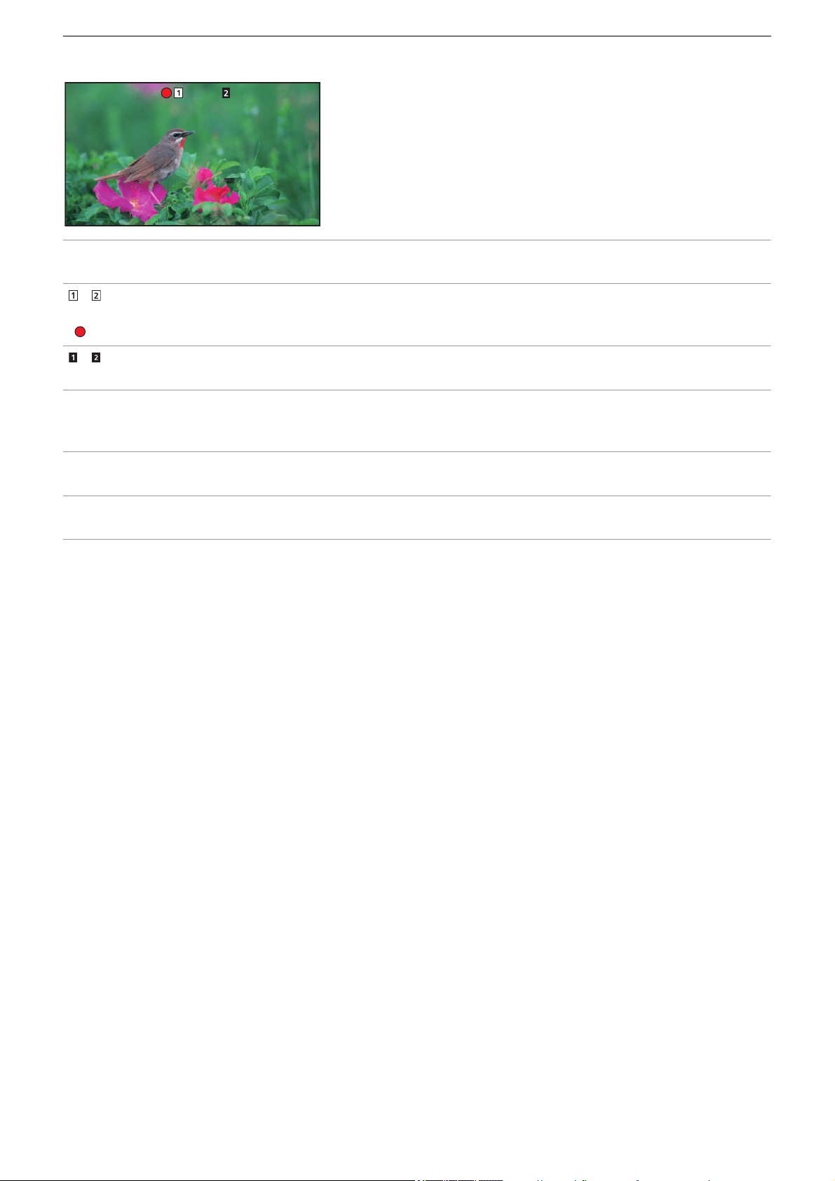
Shooting – Shooting
143
About the screen displays during recording
[TCG 00:00:00.00]:
Time data (
ÎSetting of time data: 59)
[]/[]:
Card slot number (recording target)
• is displayed on the left during recording.
[]/[]:
Card slot number
[999min]:
Remaining recording capacity in the memory card
• The display flashes when the remaining recording capacity falls below 2 minutes.
[2160-59.94p]:
Resolution, frame rate (
ÎSelecting the resolution, codec, and frame rate for recording video: 146)
[MOV HEVC 200M]:
File format, recording format (
ÎSelecting the resolution, codec, and frame rate for recording video: 146)
TCG 00:00:00.00
TCG 00:00:00.00
999min
999min
999min
999min
2160-59.94p
2160-59.94p
MOV HEVC 200M
MOV HEVC 200M

Shooting – About auto mode/manual mode
144
About auto mode/manual mode
Switch between auto mode and manual mode with the <AUTO/MANU> switch.
<AUTO>:
auto mode
• [A] is displayed at the upper part of the viewfinder and LCD monitor.
• Focus, iris, gain, shutter, and white balance are automatically adjusted.
<MANU>:
manual mode
• To adjust focus, iris, gain, shutter speed, and white balance manually, set the unit to manual mode.
• To adjust the brightness, make adjustments to the iris, the AE level, and the ND filter. (
ÎIris: 151)
• To focus manually, use the focus operation. (
ÎFocusing (manual focus): 156)
• To adjust the white balance, adjust the white balance and black balance. (
ÎAdjusting the white and black balance: 163)
• To adjust the setting of the audio input and the recording level, switch audio input. (
ÎAudio input: 182)
Camera operations that are disabled in auto mode
– The following camera operations are disabled in auto mode:
– <IRIS> button, <GAIN> button, <SHUTTER> button, <WHITE BAL> button, <FOCUS A/M/¶> switch, <PUSH AUTO>
button, <FOCUS ASSIST> button, focus ring
• The following USER button functions are disabled in auto mode:
– [AWB]/[FBC]/[PUSH AUTO]/[ATW]/[FOCUS ASSIST]
• The settings made in manual mode are not maintained for the following settings when you switch to auto mode:
– Focus, lens stop, gain, shutter speed, white balance

Shooting – Check videos recorded
145
Check videos recorded
By pressing either the USER button
*1
assigned to [REC CHECK] or touching the USER button icon after recording, you can
automatically play back the last approximately 3 seconds of the clip you have just recorded.
*1 [REC CHECK] is set in the <USER8> button at the time of purchase.
• Returns to recording standby after checking.
• REC check will not operate in following cases.
– When the power is turned ON/OFF
– When restarted
– When the <THUMBNAIL> button is pressed
– When the memory card is inserted/ejected
– When formatted the memory card
– When the USER button assigned to [SLOT SEL] has been pressed, or when the USER button icon assigned to [SLOT
SEL] has been touched to switch the card slot to be recorded to
– When switched to [CARD READER MODE] or [SERVICE MODE]
– When the [RECORDING] menu
¨ [2 SLOTS FUNC.] is set to [SIMUL REC]/[BACKGR REC]/[DUAL CODEC REC]
*2
– When either of the following settings are changed
[SYSTEM] menu
¨ [FREQUENCY]
[SYSTEM] menu
¨ [FILE FORMAT]
[SYSTEM] menu
¨ [REC FORMAT]
[RECORDING] menu
¨ [2 SLOTS FUNC.]
[RECORDING] menu
¨ [REC FUNCTION] ¨ [REC MODE]
• For USER button settings (
ÎAssigning functions to the USER buttons: 65)
*2 Available for use when using .

Shooting – Selecting the resolution, codec, and frame rate for recording video
146
Selecting the resolution, codec, and frame rate for recording video
The resolution, codec, and frame rate of the recording video can be selected.
• [SYSTEM] menu
¨ [FREQUENCY]: System frequency
• [SYSTEM] menu
¨ [FILE FORMAT]: File format for recording
• [SYSTEM] menu
¨ [REC FORMAT]: Sets the signal format and codec mode for recording.
• [SYSTEM] menu
¨ [SUPER SLOW]: Super slow recording settings
• [SYSTEM] menu
¨ [SHOOTING MODE]: Shooting mode settings according to the shooting environment
• [SCENE FILE] menu
¨ [VFR]: Variable frame rate recording function (variable frame rate range)
How to read a [REC FORMAT] setting
The item names for recording formats indicate the resolution, the frame rate, the codec mode, and the bit rate.
(However, bit rate is not included with some file formats.)
For example: When the recording format for file format [MOV] is [2160-59.94p/HEVC LongGOP 200M]
(A) Resolution
(B) Frame rate
(C) Codec mode
(D) Average bit rate
• The resolutions that can be set with this unit are as follows:
– 2160: UHD (3840×2610), 1080: FHD (1920×1080), 720: HD (1280×720)
• Smoother motion picture can be recorded with the higher value for the frame rate. [i] and [p] of the frame rate means interlace
and progressive respectively.
Interlace (interlacing scanning):
Video signal that divides the effective scanning lines to half and send them alternatively
Progressive (progressive scanning):
High density video signal sending the effective scanning lines simultaneously (It will be higher quality image than the
interlace.)
• The image quality gets higher the larger the bit rate number. However, this is not the case when the codec mode is [ALL-I].
(This is because the compression method is different.)
• When the codec mode is [ALL-I], recording is with ALL-Intra.
In this method, compression is performed at the individual frame level, so the file size increases, but it is possible to reduce
the degradation of image quality during the editing process.
• Depending on the file format settings and bit rate of the recording format, the required Speed Class for the memory cards will
differ. Use the compatible memory cards. (
ÎSpeed Class during shooting: 45)
2160 - 59.94p / HEVC LongGOP 200M
(A) (B) (C) (D)

Shooting – Selecting the resolution, codec, and frame rate for recording video
147
When [FILE FORMAT] is set to [MOV]
Video
•
When the [SYSTEM] menu
¨ [FREQUENCY] ¨ [59.94Hz] is set
• When the [SYSTEM] menu ¨ [FREQUENCY] ¨ [50.00Hz] is set
Audio
Resolution [REC FORMAT] YUV, number of bits Average bit rate
UHD (3840×2160)
[2160-59.94p/420LongGOP 150M] 4:2:0 8 bit 150 Mbps (VBR)
[2160-59.94p/HEVC LongGOP 200M]
4:2:0 10 bit
200 Mbps (VBR)
[2160-59.94p/HEVC LongGOP 100M] 100 Mbps (VBR)
[2160-29.97p/420LongGOP 100M] 4:2:0 8 bit 100 Mbps (VBR)
[2160-29.97p/HEVC LongGOP 150M] 4:2:0 10 bit
150 Mbps (VBR)
[2160-29.97p/422LongGOP 150M] 4:2:2 10 bit
[2160-23.98p/420LongGOP 100M] 4:2:0 8 bit 100 Mbps (VBR)
[2160-23.98p/HEVC LongGOP 150M] 4:2:0 10 bit
150 Mbps (VBR)
[2160-23.98p/422LongGOP 150M] 4:2:2 10 bit
FHD (1920×1080)
[1080-59.94p/422LongGOP 100M]
4:2:2 10 bit
100 Mbps (VBR)
[1080-59.94p/422ALL-I 200M] 200 Mbps (VBR)
[1080-59.94i/422LongGOP 50M] 50 Mbps (VBR)
[1080-59.94i/422ALL-I 100M] 100 Mbps (VBR)
[1080-29.97p/422LongGOP 50M] 50 Mbps (VBR)
[1080-29.97p/422ALL-I 100M] 100 Mbps (VBR)
[1080-23.98p/422LongGOP 50M] 50 Mbps (VBR)
[1080-23.98p/422ALL-I 100M] 100 Mbps (VBR)
Resolution [REC FORMAT] YUV, number of bits Average bit rate
UHD (3840×2160)
[2160-50.00p/420LongGOP 150M] 4:2:0 8 bit 150 Mbps (VBR)
[2160-50.00p/HEVC LongGOP 200M]
4:2:0 10 bit
200 Mbps (VBR)
[2160-50.00p/HEVC LongGOP 100M] 100 Mbps (VBR)
[2160-25.00p/420LongGOP 100M] 4:2:0 8 bit 100 Mbps (VBR)
[2160-25.00p/HEVC LongGOP 150M] 4:2:0 10 bit
150 Mbps (VBR)
[2160-25.00p/422LongGOP 150M] 4:2:2 10 bit
FHD (1920×1080)
[1080-50.00p/422LongGOP 100M]
4:2:2 10 bit
100 Mbps (VBR)
[1080-50.00p/422ALL-I 200M] 200 Mbps (VBR)
[1080-50.00i/422LongGOP 50M] 50 Mbps (VBR)
[1080-50.00i/422ALL-I 100M] 100 Mbps (VBR)
[1080-25.00p/422LongGOP 50M] 50 Mbps (VBR)
[1080-25.00p/422ALL-I 100M] 100 Mbps (VBR)
Codec Number of channels Number of quantizing bits Sampling frequency
LPCM 2ch 24 bits 48 kHz

Shooting – Selecting the resolution, codec, and frame rate for recording video
148
When [FILE FORMAT] is set to [MP4]
Video
•
When the [SYSTEM] menu
¨ [FREQUENCY] ¨ [59.94Hz] is set
• When the [SYSTEM] menu ¨ [FREQUENCY] ¨ [50.00Hz] is set
Audio
When [FILE FORMAT] is set to [AVCHD]
Video
•
When the [SYSTEM] menu
¨ [FREQUENCY] ¨ [59.94Hz] is set
• When the [SYSTEM] menu
¨ [FREQUENCY] ¨ [50.00Hz] is set
Audio
Resolution [REC FORMAT] YUV, number of bits Average bit rate
UHD (3840×2160)
[2160-59.94p/HEVC LongGOP 100M] 4:2:0 10 bit 100 Mbps (VBR)
[2160-29.97p/420LongGOP 72M] 4:2:0 8 bit
72 Mbps (VBR)
[2160-29.97p/HEVC LongGOP 72M] 4:2:0 10 bit
[2160-23.98p/420LongGOP 72M] 4:2:0 8 bit
[2160-23.98p/HEVC LongGOP 72M] 4:2:0 10 bit
FHD (1920×1080)
[1080-59.94p/420LongGOP 50M]
4:2:0 8 bit 50 Mbps (VBR)
[1080-23.98p/420LongGOP 50M]
Resolution [REC FORMAT] YUV, number of bits Average bit rate
UHD (3840×2160)
[2160-50.00p/HEVC LongGOP 100M] 4:2:0 10 bit 100 Mbps (VBR)
[2160-25.00p/420LongGOP 72M] 4:2:0 8 bit
72 Mbps (VBR)
[2160-25.00p/HEVC LongGOP 72M] 4:2:0 10 bit
FHD (1920×1080) [1080-50.00p/420LongGOP 50M] 4:2:0 8 bit 50 Mbps (VBR)
Codec Number of channels Number of quantizing bits Sampling frequency
AAC 2ch 16 bits 48 kHz
Resolution [REC FORMAT] YUV, number of bits Average bit rate
FHD (1920×1080)
[1080-59.94p/AVCHD PS]
4:2:0 8 bit
25 Mbps (VBR)
[1080-59.94i/AVCHD PH] 21 Mbps (VBR)
[1080-59.94i/AVCHD HA] 17 Mbps (VBR)
[1080-23.98p/AVCHD PH] 21 Mbps (VBR)
HD (1280×720) [720-59.94p/AVCHD PM] 8 Mbps (VBR)
Resolution [REC FORMAT] YUV, number of bits Average bit rate
FHD (1920×1080)
[1080-50.00p/AVCHD PS]
4:2:0 8 bit
25 Mbps (VBR)
[1080-50.00i/AVCHD PH] 21 Mbps (VBR)
[1080-50.00i/AVCHD HA] 17 Mbps (VBR)
HD (1280×720) [720-50.00p/AVCHD PM] 8 Mbps (VBR)
Codec Number of channels Number of quantizing bits Sampling frequency
Dolby Audio
™
2ch 16bits 48kHz

Shooting – Selecting the resolution, codec, and frame rate for recording video
149
About recording formats and recording functions
The file formats and recording formats corresponding to the recording functions are as follows.
• It is not possible to use recording functions with different file formats and recording formats.
* Available for use when using . (
ÎDual codec recording [X2]: 200)
• For the recordable times when using a battery (ÎStandard charging time and recordable time: 33).
• For a guide to recording times (
ÎRecording time of the memory card: 48).
• [FILE FORMAT] is set to [MOV] at the time of purchase.
• [REC FORMAT] is set as follows at the time of purchase.
– When [FREQUENCY] is set to [59.94Hz]
[2160-59.94p/HEVC LongGOP 200M]
– When [FREQUENCY] is set to [50.00Hz]
[2160-50.00p/HEVC LongGOP 200M]
• A mosaic-like noise may occur during playback when you make large or fast movements with the unit during recording or if
you record subjects that move a lot. (When recording AVCHD clips)
Recording functions [FILE FORMAT] [REC FORMAT]
Relay recording
All All
Simultaneous recording
Background recording
[MOV]
FHD (1920×1080) recording format
Dual codec recording
*
[2160-29.97p/420LongGOP 100M],
[2160-23.98p/422LongGOP 100M],
[1080-59.94p/422ALL-I 200M],
[1080-59.94p/422LongGOP 100M],
[1080-59.94i/422ALL-I 100M],
[1080-29.97p/422ALL-I 100M],
[1080-23.98p/422ALL-I 100M],
[2160-25.00p/420LongGOP 100M],
[1080-50.00p/422ALL-I 200M],
[1080-50.00p/422LongGOP 100M],
[1080-50.00i/422ALL-I 100M],
[1080-25.00p/422ALL-I 100M]
Interval recording All
Variable frame rate (VFR)
[2160-59.94p/420LongGOP 150M],
[2160-59.94p/HEVC LongGOP 200M],
[2160-59.94p/HEVC LongGOP 100M],
[2160-29.97p/420LongGOP 100M],
[2160-29.97p/HEVC LongGOP 150M],
[2160-29.97p/422LongGOP 150M],
[2160-23.98p/420LongGOP 100M],
[2160-23.98p/HEVC LongGOP 150M],
[2160-23.98p/422LongGOP 150M],
[1080-59.94p/422LongGOP 100M],
[1080-59.94p/422ALL-I 200M],
[1080-29.97p/422LongGOP 50M],
[1080-29.97p/422ALL-I 100M],
[1080-23.98p/422LongGOP 50M],
[1080-23.98p/422ALL-I 100M],
[2160-50.00p/420LongGOP 150M],
[2160-50.00p/HEVC LongGOP 200M],
[2160-50.00p/HEVC LongGOP 100M],
[2160-25.00p/420LongGOP 100M],
[2160-25.00p/HEVC LongGOP 150M],
[2160-25.00p/422LongGOP 150M],
[1080-50.00p/422LongGOP 100M],
[1080-50.00p/422ALL-I 200M],
[1080-25.00p/422LongGOP 50M],
[1080-25.00p/422ALL-I 100M]
Super slow recording function
[1080-59.94p/422LongGOP 100M],
[1080-29.97p/422LongGOP 50M],
[1080-23.98p/422LongGOP 50M],
[1080-50.00p/422LongGOP 100M],
[1080-25.00p/422LongGOP 50M]
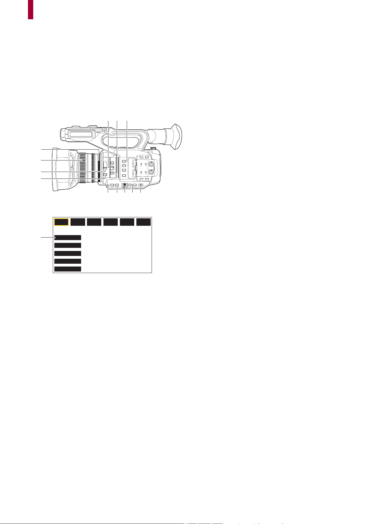
150
Adjustable settings when shooting
This chapter describes how to adjust factors such as the lens stop and gain.
≥Iris: 151
≥Gain: 152
≥AE level (exposure compensation): 154
≥Brightness adjustment: 155
≥Focus: 156
≥Setting the shutter speed: 159
≥Area mode function: 161
(A) Iris ring
(B) Focus ring
(C) <ND FILTER> switch
(D) <IRIS> button
(E) <FOCUS A/M/¶> switch
(F) <PUSH AUTO> button
(G) <USER1> button
(H) <GAIN> button
(I) <SHUTTER> button
(J) Multidial
(K) <EXIT> button
(L) <AUTO/MANU> switch
(M) [USER10] button icon ([FOCUS MACRO] is allocated at the time of purchase.)
(A)
(E) (F) (G)
(H) (I) (J) (L)
(B)
(C)
(D)
F1:
FOCUS MACRO
BACKLIGHT
FACE DETECT
ATW LOCK
MENU
F2:
FLUO
F3:
SPARK
F4:
STILL
F5:
CINE
F6:
HLG
(M)
(K)
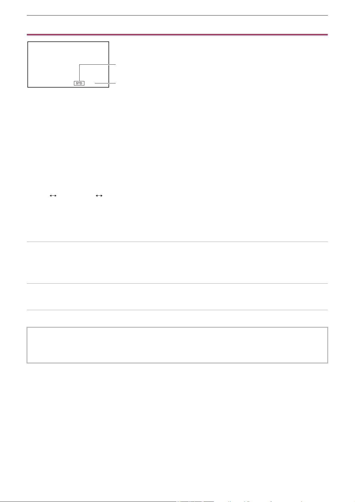
Adjustable settings when shooting – Iris
151
Iris
(A) Auto iris icon
• Displayed when in the auto iris mode.
(B) Iris value
1
Switch to manual mode with the <AUTO/MANU> switch. (ÎAbout auto mode/manual
mode: 144
)
2
Press the <IRIS> button to switch to manual iris mode.
[STD] disappears.
3
Rotate the iris ring.
Iris value
CLOSE (F11 to F3.0) OPEN
•
Value closer to CLOSE darken the image.
• Value closer to OPEN brighten the image.
Applications for the USER button
When adjusting the iris (the lens stop), it is convenient to use the following USER button functions.
[BACKLIGHT]:
Switches to the auto iris control for backlight compensation. Prevents the subject darkening due to backlight coming from behind
and hitting them, so you can brighten the images on the screen.
• The auto iris icon changes to [BACK].
• [BACKLIGHT] is set in the [USER11] button icon at the time of purchase.
[SPOTLIGHT]:
Switches to the auto iris control for the spotlight. Even extremely bright subjects can be recorded well.
• The auto iris icon changes to [SPOT].
• For USER button settings (ÎAssigning functions to the USER buttons: 65)
• Iris adjustments are not possible when IR recording is enabled.
• Depending on the zoom magnification, there are iris values that are not displayed.
• In Auto Gain Mode or Auto Shutter Mode, the screen brightness may not change even if you adjust the iris. (
ÎGain: 152,
Setting the shutter speed: 159)
F5.6
(A)
(B)

Adjustable settings when shooting – Gain
152
Gain
If the camera screen is dark, increase the gain to brighten the screen.
(A) Gain value
• [AGC] is displayed in auto gain mode and dB is displayed in manual gain mode.
(B) GAIN
1
Switch to manual mode with the <AUTO/MANU> switch. (ÎAbout auto mode/manual
mode: 144
)
2
Press the <GAIN> button to switch to manual gain mode.
The gain display is highlighted in orange.
3
Turn the multidial to adjust, then press the multidial.
The setting changes to the value displayed and exits.
Press the <EXIT> button to exit without changing the setting.
Gain value
0dB to 24dB
*
• Value closer to [0dB] darken the image.
• Value closer to [24dB] brighten the image.
* When [SYSTEM] menu
¨ [SHOOTING MODE] ¨ [HIGH SENS.], the adjustment range is between [−3dB] and [24dB].
• The set gain value is not maintained in the following cases:
– The <GAIN> button is pressed
– When switched to auto mode
• Screen noise increases when you raise the gain value.
• When auto iris mode or auto shutter mode is enabled, the brightness of the screen may not change even when you adjust
the gain. (
ÎIris: 151, Setting the shutter speed: 159)
GAIN
24dB
(B)
(A)

Adjustable settings when shooting – Gain
153
Super gain
You can set super gain when recording in dark places.
1
In [CAMERA] menu ¨ [SW MODE] ¨ [SUPER GAIN], select one of [SUPER GAIN],
[SUPER GAIN+], or [ALL].
2
Either press the USER button assigned to [S.GAIN] or touch the USER button icon.
(
ÎAssigning functions to the USER buttons: 65)
Gain switches to the one selected in Step 1.
• The gain value switches to [SG] or [SG+].
• When [ALL] is selected in Step 1, each time you either press the USER button or touch the USER button icon, the
selection changes in the order [SG] ([SUPER GAIN]), [SG+] ([SUPER GAIN+]), normal gain.
• Super gain is cleared in the following cases:
– When the power is turned off
– When the <AUTO/MANU> switch is switched
– The <GAIN> button is pressed in manual mode
• Super gain cannot be used in the following cases:
– When the [SYSTEM] menu
¨ [SHOOTING MODE] is set to [HIGH SENS.]
– When IR recording is enabled

Adjustable settings when shooting – AE level (exposure compensation)
154
AE level (exposure compensation)
(A) Exposure compensation value
(B) AE LEVEL
Adjusting with the iris ring
1
Switch to auto iris mode.
• Do one of the following:
– Set the <AUTO/MANU> switch to <AUTO>.
– Set the <AUTO/MANU> switch to <MANU> and press the <IRIS> button to set to auto iris mode.
2
Select the [SCENE FILE] menu ¨ [AE LEVEL] ¨ [ON].
3
Rotate the iris ring.
The set exposure compensation value is also reflected in the [SCENE FILE] menu ¨ [AE LEVEL EFFECT] menu setting.
AE level
−2.0EV to +2.0EV
•
Value closer to −2.0EV darken the image.
• Value closer to +2.0EV brighten the image.
Setting with the multi manual function
When [AE LEVEL] is set to [ON], you can adjust the AE level with the following procedure:
1
Switch one of iris, gain, or shutter speed to auto.
2
Turn the multidial to display [ AE LEVEL].
3
Press the multidial.
The AE level display is highlighted in orange.
4
Turn the multidial to adjust, then press the multidial.
The setting changes to the value displayed and exits.
Press the <EXIT> button to exit without changing the setting.
Applications for the USER button
You can also either press the USER button assigned to [AE LEVEL] or touch the USER button icon to switch enable/disable of
[AE LEVEL].
• [AE LEVEL] is set in the <USER2> button at the time of purchase.
• For USER button settings (
ÎAssigning functions to the USER buttons: 65)
• AE level adjustments are not possible when IR recording is enabled.
AE LEVEL
+1.0EV
(A)
(B)
Adjustable settings when shooting – Brightness adjustment
155
Brightness adjustment
When the external light is strong, you can switch the ND filter (brightness adjustment filter) to use with the <ND FILTER> switch.
1
Change the setting of the <ND FILTER> switch.
(A) ND filter setting value
(B) Recommended ND filter setting value
<1/64>:
Reduces the amount of light entering the MOS sensor to 1/64.
<1/16>:
Reduces the amount of light entering the MOS sensor to 1/16.
<1/4>:
Reduces the amount of light entering the MOS sensor to 1/4.
<CLR>:
Does not use the ND filter.
• If the selected setting <1/64>, <1/16> or <1/4> does not match an ND filter setting recommended by this unit, the
recommended setting will be displayed on the screen, blink for approximately 5 seconds and disappear.
• The ND filter cannot be used when IR recording is enabled.
• The recommended ND filter setting value may not be displayed correctly when the scene is too dark.
ND1/16
ND1/64
(A)
(B)
Adjustable settings when shooting – Focus
156
Focus
Focusing (manual focus)
(A) Focus value
• The focus mode ([AF]/[MF]) and the focus value are displayed.
• The units for the focus value can be changed in the [ZOOM/FOCUS] menu. (Î[ZOOM/FOCUS]: 104)
1
Switch to manual mode with the <AUTO/MANU> switch. (ÎAbout auto mode/manual
mode: 144
)
2
Switch to manual focus mode using the <FOCUS A/M/¶> switch.
<A>:
Changes to the auto focus mode. The auto focus mode adjusts the focus automatically. You can also temporarily adjust the
focus manually by turning the focus ring.
<M>:
Changes to the manual focus mode. Control the focus ring manually to adjust the focus.
<¶>:
If you move the <FOCUS A/M/¶> switch towards <¶>, focus will be adjusted to MF95 on the infinity side. (The <FOCUS
A/M/¶> switch will return to the <M> position.)
3
Turn the focus ring.
The focus value can be set between MF00 (focal distance
*1
: approximately 10 cm (3.93 q) or approximately
1 m (approx.
3.3 feet)
*2
) and MF99 (focal distance: infinity). The higher the number the further away the object is to be focused on.
*1 Focal distance is the distance to the subject to be focused on.
*2 When [FOCUS MACRO]/[MACRO] is enabled: the subjects are focused at approximately
10 cm (3.93 q) or more.
When [FOCUS MACRO]/[MACRO] is disabled: the subjects are focused at approximately
1 m (approx. 3.3 feet) or
more.
Macro
Macro function can be switched [ON]/[OFF].
1
Press the USER button to which [FOCUS MACRO] is assigned or touch the USER
button icon.
• It is set in the [USER10] button icon at the time of purchase.
• When [ON] is set, is displayed at the top of the focus display on the viewfinder or LCD monitor.
• Since the auto focus control may not operate properly if there is a flicker, select a shutter speed that is appropriate to the
light.
• If you set the unit to auto focus mode at times other than 59.94i (50.00i) and 59.94p (50.00p), the time required for the focus
control will be slightly longer than when in normal focus mode.
• In auto mode, it is not possible to switch to the manual focus mode.
• This can also be set with the [CAMERA] menu
¨ [SW MODE] ¨ [MACRO].
MF50
(A)

Adjustable settings when shooting – Focus
157
Auto focusing
The following functions are available with the <PUSH AUTO> button, USER button assigned to [PUSH AUTO], or the USER
button icon, when manual focus mode is on.
One press AF function:
When you press the button, or touch the USER button icon, auto focus mode is turned on and automatic focusing occurs at high
speed until the camera focuses.
• The camera returns to manual focus mode when it focuses or after a certain time has elapsed.
Press AF function:
While the button is being pressed, or the USER button icon is being touched, the camera temporarily switches to auto focus
mode.
• The focus position is automatically adjusted to suit the subject in the center of the screen.
• When [AREA MODE] is set to [FOCUS], [FOCUS/IRIS], or [FOCUS/Y GET] and the area function is used, the focus position
is automatically adjusted to suit the subject that was touched. (
ÎArea mode function: 161)
• The function cancels when you release the button and the focus position set while press AF was set is maintained.
• For USER button settings (ÎAssigning functions to the USER buttons: 65)
AF area width adjustment
You can adjust the effective area width for auto focus according to the size of the subject.
1
Switch to auto focus mode.
• Make one of the following settings:
– Set the <AUTO/MANU> switch to <AUTO>.
– Set the <AUTO/MANU> switch to <MANU> and <FOCUS A/M/¶> switch to <A>.
2
Select [CAMERA] menu ¨ [SW MODE] ¨ [AF AREA WIDTH] ¨ [ON].
When you press the <MENU> button to quit the menu, the AF area frame is displayed.
(A) AF area frame
3
Turn the multidial to adjust the AF area frame.
4
Press the multidial.
The setting changes and exits.
Press the <EXIT> button to exit without changing the setting.
Setting with the multi manual function
When [AF AREA WIDTH] is [ON], you can adjust the AF area frame with the following procedure:
1
Switch to auto focus mode.
2
Turn the multidial to display [ AF AREA].
3
Press the multidial.
AF area frame will be displayed.
4
Turn the multidial to adjust the AF area frame.
5
Press the multidial.
(A)

Adjustable settings when shooting – Focus
158
Utilizing the USER button
You can also either press the USER button assigned to [AF AREA] or touch the USER button icon to switch enable/disable of
[AF AREA WIDTH].
• For USER button settings (
ÎAssigning functions to the USER buttons: 65)
• While the AF area frame is adjusted, performing any of the following operations will end the adjustment:
– Set to manual gain mode
– Set to manual shutter mode
– Switch white balance to “VAR”
• To cancel the settings, set [AF AREA WIDTH] to [OFF].
• In the following cases, this cannot be set.
– In manual focus mode
– When using Area Mode (
ÎArea mode function: 161)
Adjustable settings when shooting – Setting the shutter speed
159
Setting the shutter speed
(A) Shutter speed
• [A.SHTR] is displayed when the auto shutter mode is on.
(B) SHUTTER
1
Switch to manual mode with the <AUTO/MANU> switch. (ÎAbout auto mode/manual
mode: 144
)
2
Press the <SHUTTER> button to switch to manual shutter mode.
The shutter speed display is highlighted in orange.
3
Turn the multidial to select the shutter speed.
4
Press the multidial.
The setting changes to the value displayed and exits.
Press the <EXIT> button to exit without changing the setting.
Adjusting the shutter speed
Shutter speed changes depending on the frame rate of the [REC FORMAT]. (
ÎSelecting the resolution, codec, and frame rate
for recording video: 146
)
• The shutter speed is faster the closer the setting is to 1/8000.
Frame rates Shutter speed
59.94p/59.94i 1/8 1/15 1/30 1/60 ...1/8000
29.97p 1/8 1/15 1/30 1/50 ...1/8000
50.00p/50.00i/25.00p 1/6 1/12 1/25 1/50 ...1/8000
23.98p 1/6 1/12 1/24 1/48 ...1/8000
SHUTTER
1/60
(A)
(B)

Adjustable settings when shooting – Setting the shutter speed
160
Synchro scan shutter speed
Fine-adjusting the shutter speed will minimize flickering and horizontal bars in images.
(C) Synchro scan shutter speed
1
Switch to manual mode with the <AUTO/MANU> switch.
2
Press the <SHUTTER> button to switch to manual shutter mode.
The shutter speed display is highlighted in orange.
3
Select [SCENE FILE] menu ¨ [SYNC SCAN] ¨ [ON].
4
Adjust the Synchro Scan setting by rotating the multidial.
To minimize flickering and horizontal bands, look at the screen while adjusting the shutter speed.
5
Press the multidial.
The setting changes to the value displayed and exits.
Press the <EXIT> button to exit without changing the setting.
• The set shutter speed will also be applied to the [SYNC SCAN SETTING] menu setting. (
Î[SYNC SCAN SETTING]: 87)
• Brightly shining objects and highly reflective objects may emit light bands into the surroundings.
• The changing of the screen may not look smooth in normal playback.
• When extremely bright subjects are recorded or when recording is performed inside under lights, there may be changes in
the color hue and brightness of the screen, with horizontal bands appearing on the screen. Do the following if this occurs:
– Switch to auto shutter mode.
– Adjust the shutter speed to 1/50, 1/60, or 1/100.
– Adjusting with the synchro scan shutter speed
• When auto iris mode or auto gain mode is enabled, the brightness of the screen may not change even when you adjust the
shutter speed. (
ÎIris: 151, Gain: 152)
• When the shutter speed has been set to slow shutter, it may not be possible for the camera to keep up with changes in the
images. If this occurs, set the iris, focus, and white balance manually.
SYNCHRO
1/60.0
(C)

Adjustable settings when shooting – Area mode function
161
Area mode function
Touch the subject to apply various effects tailored to the subject that is touched.
• Area auto focus function
Adjusts the focus automatically tailored to the subject that is touched.
• Area auto iris level function
Adjusts the iris automatically tailored to the subject that is touched.
• Area brightness display
Displays the luminance level of the subject that is touched.
Operation function settings
Sets the operation to be assigned to the area mode function from the [CAMERA] menu.
1
Select the desired function in the [CAMERA] menu ¨ [SW MODE] ¨ [AREA MODE].
[INHIBIT]:
Does not assign a function.
[FOCUS]:
Sets the area auto focus function
[IRIS]:
Area auto iris function
[Y GET]:
Area brightness display
[FOCUS/IRIS]:
Simultaneous operation of the area auto focus function and area auto iris function
[FOCUS/Y GET]:
Simultaneous operation of the area auto focus function and area brightness display
Operation of area mode function
The function set in the [CAMERA] menu
¨ [SW MODE] ¨ [AREA MODE] can be used by performing the following operation
when shooting or while in shooting standby.
1
Either press the USER button assigned to [AREA] or touch the USER button icon.
(
ÎAssigning functions to the USER buttons: 65)
• [AREA] is set in the <USER1> button at the time of purchase.
• The area frame (A) is displayed, and the is displayed on the right side of the screen.
• When the area brightness display is activated, the brightness display in the center does not operate.
2
Touch the shooting screen.
• The area frame is displayed in the area that is touched to apply the effects set in the menu.
3
Press the USER button or touch the USER button icon
*
again.
• The area frame disappears and the unit exits the area mode function.
* To display the USER button icon, touch and hold the screen.
(A)

Adjustable settings when shooting – Area mode function
162
Adjusting the area size
1
Turn the multidial to display the [ AREA].
2
Press the multidial.
3
Turn the multidial to change the size of the area frame.
It changes in 3 stages.
4
Press the multidial.
The setting is changed to the displayed size and exits.
The setting is changed and exits also by pressing the <EXIT> button.
• The area mode function is canceled when the power is turned off or when the thumbnail screen is displayed.
• The area mode cannot be used when the digital zoom is enabled.
AREAAREA
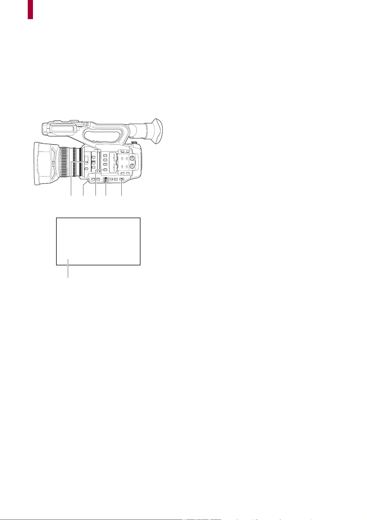
163
Adjusting the white and black balance
To obtain high-quality video at all times using the unit, the white and black balance must be adjusted according to conditions.
Adjust the AWB (white balance adjustment), ABB (black balance adjustment), and AWB (white balance adjustment) in order to
obtain higher image quality.
• White balance settings are not possible when IR recording is enabled.
• White balance/black balance adjustment is done using the [AWB] USER button function. Make the settings beforehand.
(
ÎAssigning functions to the USER buttons: 65)
It is set in the <USER9> button at the time of purchase.
≥White balance adjustment: 164
≥Black balance adjustment: 167
(A) <ND FILTER> switch
(B) <USER9> button
(C) <WHITE BAL> button
(D) Multidial
(E) <AUTO/MANU> switch
(F) Color temperature
• The white balance being set is displayed.
(A) (B) (C) (D)
(E)
(F)
A 3200K

Adjusting the white and black balance – White balance adjustment
164
White balance adjustment
≥Setting the variable value for the white balance: 165
≥Settings of the auto tracking white balance (ATW) function: 166
Follow the steps below to adjust the white balance automatically.
When stored in white balance “Ach”
1
Switch to manual mode with the <AUTO/MANU> switch. (ÎAbout auto mode/manual
mode: 144
)
2
Set the gain value. (ÎGain: 152)
Normally, set this to 0 dB. If it is too dark, set the gain to an appropriate value.
3
Press the <WHITE BAL> button to switch to “Ach”.
Each time you press the button, the white balance switches in the order “Preset”, “Ach”, “Bch”.
4
Change the <ND FILTER> switch settings according to the light conditions.
• For setting examples for the <ND FILTER> switch (ÎBrightness adjustment: 155)
5
Place the white pattern at a point where the light conditions match those for the light
source for the subject, and zoom in on the white pattern so that the white color
appears in the screen.
6
Adjust the iris (the lens stop).
Adjust the iris so that the brightness of Y GET is approx. 70 %.
7
Either press the USER button assigned to [AWB] or touch the USER button icon.
Automatic adjustment of the white balance starts and the white balance adjustment value is memorized.
White pattern
• A white object (cloth or wall) near the subject may also be used for the white pattern.
• Required size of white pattern is as follows.
(A) 1/2 or more of the screen width
(B) 1/2 or more of the screen height
• Keep bright spotlights out of the screen.
• The white pattern must be placed at the center of the screen.
• The content previously set is maintained in “Ach” or “Bch”. Make the settings again if the lighting conditions have changed.
• You can make fine adjustments of the color hue using the [RB GAIN CONTROL SETTING]. (Î[RB GAIN CONTROL
SETTING]: 88
)
• For details about the viewfinder and LCD monitor screen displays relating to white balance (
ÎScreen display during
shooting: 245
)
(A)
(B)
Adjusting the white and black balance – White balance adjustment
165
Messages displayed in the viewfinder and LCD monitor
• When the auto tracking white balance (ATW) function is operating, white balance cannot be adjusted.
When the white balance has not been automatically adjusted
When the white balance has not been successfully adjusted, an error message is displayed on the viewfinder screen and LCD
monitor displays.
When having no time to adjust the white balance
1
Press the <WHITE BAL> button to switch to “Preset”.
When switched to “Preset”, the white balance set in [W.BAL PRESET] is displayed. (
Î[W.BAL PRESET]: 81)
2
Either press the USER button assigned to [AWB] or touch the USER button icon to
switch the white balance.
[P 3200K], [P 5600K], and “VAR” (the value set in the [CAMERA] menu
¨ [SW MODE] ¨ [W.BAL VAR]) change in order.
• When “VAR” is selected, turning the multidial can set any white balance value between [V 2000K] and [V 15000K].
Setting the variable value for the white balance
The color temperature of white balance can be adjusted by the setting menu.
(A) “VAR” setting value
1
Press the <WHITE BAL> button to switch to “Preset”.
2
Either press the USER button assigned to [AWB] or touch the USER button icon to
switch to “VAR”.
The setting values for [ WB] and “VAR” are displayed on the camera image screen.
3
In the [CAMERA] menu ¨ [SW MODE] ¨ [W.BAL VAR], set the color temperature.
This can be set from [2000K] to [15000K].
Status Message Remark
During adjustment [AWB A ACTIVE] —
Adjustment completed [AWB A OK]
• The adjusted value is automatically stored in the specified
memory (A or B).
When the color temperature of the
subject is lower than 2000 K or higher
than 15000 K
[AWB NG <COLOR TEMP LOW>]
[AWB NG <COLOR TEMP HIGH>]
• [AWB NG <COLOR TEMP LOW>] indicates that the
temperature is lower than the displayed temperature. [AWB
NG <COLOR TEMP HIGH>] indicates that the temperature
is higher than the displayed color temperature.
Error message Meaning Remedy
[AWB NG <LOW LIGHT>] There is insufficient light. Increase the amount of light or increase gain.
[AWB NG <LEVEL OVER>] There is too much light. Decrease the amount of light or decrease gain.
[AWB NG <COLOR TEMP HIGH>] or
[AWB NG <COLOR TEMP LOW>]
The color temperature is too high, or
too low.
Use the appropriate filter or light source.
(A)
V 2000K
WB
Adjusting the white and black balance – White balance adjustment
166
Setting with the multi manual function
1
Press the <WHITE BAL> button to switch to “Preset”.
2
Either press the USER button assigned to [AWB] or touch the USER button icon to
switch to “VAR”.
The setting values for [ WB] and “VAR” are displayed on the camera image screen.
The “VAR” setting value is highlighted in orange.
3
Turn the multidial to select the color temperature.
4
Press the multidial.
The setting changes to the value displayed and exits.
Press the <EXIT> button to exit without changing the setting.
Settings of the auto tracking white balance (ATW) function
The unit is equipped with the Auto Tracking White Balance (ATW) function that automatically tracks the white balance of images
according to the lighting conditions.
The auto tracking white balance function can be assigned to each of “Ach”, “Bch”, and “Preset” in white balance.
Set the function with the [CAMERA] menu
¨ [SW MODE] ¨ [ATW].
Applications for the USER button
[ATW]:
Switches enable/disable of the ATW function.
[ATW LOCK]:
Locks the white balance value adjusted with the ATW function. This is enabled when the white balance setting is [ATW].
• For USER button settings (ÎAssigning functions to the USER buttons: 65)
Canceling the auto tracking white balance
Switch white balance by pressing the USER button assigned to the [ATW] again, touching the USER button icon again, or
pressing the <WHITE BAL> button. However, with white balance set in [CAMERA] menu
¨ [SW MODE] ¨ [ATW], it is not
canceled by pressing the USER button.
• The “VAR” value displayed on the camera image screen is not guaranteed to be an absolute value. Use it for reference
purposes only.
• [ATW] is displayed on the camera image screen when the ATW function is enabled.
• [LOCK] is displayed on the camera image screen when the [ATW LOCK] function is enabled.
• The [AWB] USER button is disabled when the ATW function is enabled.
• By adjusting [ATW TARGET R] and [ATW TARGET B] individually, you can set ATW to suit the recording conditions.
(
Î[ATW TARGET R]: 81)
• This function does not guarantee 100 % accuracy for the white balance. Note that the tracking performance relative to
changes in ambient lighting and white balance performance has been given a certain degree of latitude.

Adjusting the white and black balance – Black balance adjustment
167
Black balance adjustment
Black balance must be adjusted in the following instances:
• When the unit is used for the first time
• When used after a long period of time without use
• When the ambient temperature has changed considerably
• When super gain is set with the USER button
• When changing the gain values
• When switching items in the [SYSTEM] menu
¨ [REC FORMAT].
To shoot optimum video, we recommend adjusting the black balance immediately before shooting.
Before adjusting the black balance, prepare the conditions for adjusting the white balance.
1
Switch to manual mode with the <AUTO/MANU> switch. (ÎAbout auto mode/manual
mode: 144
)
2
Press the <WHITE BAL> button to switch to “Ach” or “Bch”.
Each time you press the button, the white balance switches in the order “Preset”, “Ach”, “Bch”.
3
Either press and hold the USER button assigned to [AWB] for approximately
2 seconds or touch and hold the USER button icon for approximately 2 seconds.
After adjustment of the black balance, white balance is then adjusted, and the black balance/white balance adjustment
values are memorized.
If white balance has been set elsewhere other than in “Ach” and “Bch”, then only the black balance is adjusted.
Messages displayed in the viewfinder and LCD monitor
Black balance memory
Values stored to memory are saved even if the unit is turned off.
Status Message Remark
During adjustment [ABB ACTIVE] —
Adjustment completed [ABB OK]
• The adjusted value is automatically stored
in the specified memory (A or B).
• The content previously set is maintained in “Ach” or “Bch”. Make the settings again if the lighting conditions have changed.
• During black balance adjustment, the aperture is set to automatically shut out light.
• During recording, black balance cannot be adjusted.
• Video is not recorded to the memory card even if the REC button is pressed while executing the automatic black balance.
• While adjusting the black balance, the gain circuitry in the device automatically switches to perform adjustments. Flicker or
noise sometimes appears on the viewfinder screen and LCD monitor. This is not a malfunction.


Using the zoom function – Adjusting the zoom position
169
Adjusting the zoom position
≥About the zoom speed: 169
≥Using i.ZOOM: 170
≥Using fast zoom: 170
The zoom can be operated at the following 3 locations:
• Zoom lever (on the handle)
• Zoom lever (on the grip)
• Zoom ring
(A) Zoom lever (on the handle)/(B) Zoom lever (on the grip)
<T>: Zoom in the image.
<W>: Zoom out the image.
(C) Zoom ring
A side: Zoom out the image.
B side: Zoom in the image.
• In the [ZOOM RING] menu, you can also change the turn direction for the zoom ring and change the zoom control.
(
Î[ZOOM RING]: 80)
(D) Zoom ratio
• The zoom ratio can be confirmed between [Z00]/[iZ00] (maximum wide angle) to [Z99]/[iZ99] (maximum telephoto) on the
screen display. The value becomes higher as the unit zooms in and smaller as the unit zooms out.
About the zoom speed
• The zoom speed changes with the amount that the zoom lever (on the grip) is pushed or the speed that the zoom ring is
turned.
• The zoom is at a steady rate with the zoom lever (on the handle).
Performs the zoom operation with the speed set in the [CAMERA] menu
¨ [SW MODE] ¨ [H.ZOOM SPEED].
• If you take your finger off the zoom lever during zoom operation, the operation sound may be recorded. When returning the
zoom lever to the original position, move it quietly.
• The units for the zoom ratio can be changed in the [ZOOM/FOCUS] menu. (
Î[ZOOM/FOCUS]: 104)
(B)
(A)
A
B
A
B
(C)
Z00
(D)

Using the zoom function – Adjusting the zoom position
170
Using i.ZOOM
When [i.ZOOM] is set to [ON], you can zoom to a maximum of approximately 32× (approximately 24× when recording with UHD)
while maintaining the beauty of high-definition image quality.
1
Select the [CAMERA] menu ¨ [SW MODE] ¨ [i.ZOOM] ¨ [ON].
• You can set [i.ZOOM] in a USER button so that you can use iZoom. (
ÎAssigning functions to the USER buttons: 65)
• The zoom ratio display changes.
(For example)
– iZ00 to iZ99: Optical zoom range
– Z99: In iZoom
Using fast zoom
When [FAST ZOOM] is assigned to a USER button, you can use fast zoom by operating the zoom lever (on the grip).
1
Select the [CAMERA] menu ¨ [USER SW] ¨ [USER1] to [USER14] ¨ [FAST ZOOM].
2
Either press the USER button assigned to [FAST ZOOM] or touch the USER button
icon.
3
Push the zoom lever (on the grip) until the end to zoom.
• The zoom ratio display changes during fast zoom. (For example: 99)
• When the [CAMERA] menu ¨ [SW MODE] ¨ [H.ZOOM SPEED] is set to [7], fast zoom can also be used by operating the
zoom lever (on the handle).
• As the operating noise of fast zoom will be louder than normal, the operating noise may be recorded during recording. If the
operating noise is a problem, disable [FAST ZOOM].
• Auto focus may not be able to keep up during fast zoom, depending on the subject.
• Fast zoom cannot be used in the following case:
– When interval recording is enabled

171
Image quality adjustment
The image quality of the video to record can be set in the [SCENE FILE] menu. Measurement equipment such as a vector scope
is necessary to change “Advanced settings”.
≥Detail function: 172
≥Skin tone function: 173
≥RB gain control function: 174
≥Chroma setting function: 175
≥Matrix function: 176
≥Color correction function: 177
≥Black control function: 178
≥Gamma function: 179
≥Knee function: 180
≥White clip function: 181

Image quality adjustment – Detail function
172
Detail function
This function thickens or weakens the outlines of images. It effectively softens or sharpens images, but in some cases, the
whole image may become rough due to emphasized noise and edges. To avoid such problems, it is necessary not to add this
effect on parts where emphasizing is not needed and keep the details of the parts.
General settings
[MASTER DTL]:
Sets the level of the detail effect as a whole.
[DTL CORING]:
Sets the level of signal (including noise) so that the detail effect does not activate.
Advanced settings
[V.DTL LEVEL]:
Sets the intensity of the detail level in the vertical direction.

Image quality adjustment – Skin tone function
173
Skin tone function
This function makes human skin look smoother in images.
General settings
[SKIN TONE DTL.]
Advanced settings
[SKIN DTL EFFECT]:
Sets the effect level of the skin tone detail.

Image quality adjustment – RB gain control function
174
RB gain control function
This is a function that adds or reduces the intensities of reds and blues when the white balance setting is “Preset”, “Ach” or
“Bch”. It works when auto white balance is enabled.
• It does not work when the white balance setting is [ATW].
General settings
Use the unit with the factory settings.
Advanced settings
Set with the [SCENE FILE] menu
¨ [RB GAIN CONTROL SETTING].
• When the white balance setting is “Preset”
[R GAIN AWB PRE]:
Sets to add or reduce the intensity of the red color.
[B GAIN AWB PRE]:
Sets to add or reduce the intensity of the blue color.
• When the white balance setting is “Ach”
[R GAIN AWB A]:
Sets to add or reduce the intensity of the red color.
[B GAIN AWB A]:
Sets to add or reduce the intensity of the blue color.
• When the white balance setting is “Bch”
[R GAIN AWB B]:
Sets to add or reduce the intensity of the red color.
[B GAIN AWB B]:
Sets to add or reduce the intensity of the blue color.
• When the white balance setting is “Ach” and auto white balance is performed
[AWB A GAIN OFFSET]:
Sets whether to keep or reset the values set for [R GAIN AWB A] and [B GAIN AWB A].
• When the white balance setting is “Bch” and auto white balance is performed
[AWB B GAIN OFFSET]:
Sets whether to keep or reset the values set for [R GAIN AWB B] and [B GAIN AWB B].

Image quality adjustment – Chroma setting function
175
Chroma setting function
This function sets color saturation and phase. It applies effects on whole images. It cannot be set to individual color hue.
General settings
[CHROMA LEVEL]:
Sets the chroma level of the signal and signal. When the vector scope is used, the distance from the center (no color) is
increased or decreased for the entire image.
[CHROMA PHASE]:
Finely adjusts the chroma phase of the signal and signal. When the vector scope is used, the whole image rotates
clockwise or counter-clockwise.
Advanced settings
No setting items are provided.
P
R
P
B
P
R
P
B

Image quality adjustment – Matrix function
176
Matrix function
This function sets the image color representation by selecting the matrix table.
General settings
[MATRIX TYPE]:
Selects the matrix table to represent the color for shooting.
Advanced settings
Set with the [SCENE FILE] menu
¨ [MATRIX].
[ADAPTIVE MATRIX]:
Controls the color collapse under intense blue light source.

Image quality adjustment – Color correction function
177
Color correction function
This function sets color saturation and phase. Each of the 16 divisions of color hue can be set individually.
(A) (Axis to operate)
General settings
Use the unit with the factory settings.
Advanced settings
Set with the [SCENE FILE] menu
¨ [COLOR CORRECTION].
[R]/[R-R-Mg]/[R-Mg]/[Mg]/[Mg-B]/[B]/[B-Cy]/[Cy]/[Cy-G]/[G]/[G-Yl]/[G-Yl-Yl]/[Yl]/[Yl-Yl-R]/[Yl-R]/[Yl-R-R]:
Changes the phase and saturation. When setting the phase, + is clockwise and − is counter-clockwise.
R: Red
P1: (Yl-R)-R
P2: (Yl-R)
P3: Yl-(Yl-R)
YI: Yellow
P4: (G-Yl)-Yl
P5: (G-Yl)
G: Green
P6: (Cy-G)
Cy: Cyan
P7: (B-Cy)
B: Blue
P8: (Mg-B)
Mg: Magenta
P9: (R-Mg)
P10: R-(R-Mg)
R
Mg
G
Cy
B
Yl
P10
P9
P8
P7P6
P5
P4
P3
P2
P1
(A)
SAT(−)
PHASE(+)
(−)
(+)

Image quality adjustment – Black control function
178
Black control function
This function sets the black level that is to be the reference of luminance.
General settings
[MASTER PED]:
Sets the reference black level. RGB also changes by changing this setting. − tends to make black recede, + tends to make black
stand out.
Advanced settings
There are no setting items.

Image quality adjustment – Gamma function
179
Gamma function
This function optimizes the tone of images.
General settings
[GAMMA MODE SEL]:
Selects a gamma mode.
Advanced settings
Set with the [SCENE FILE] menu
¨ [GAMMA SETTING].
[BLACK GAMMA]:
Sets the gamma curve compression and expansion of dark areas.
[B.GAMMA RANGE]:
Sets the maximum level to perform compression/expansion.

Image quality adjustment – Knee function
180
Knee function
This function sets the compression of video signals to prevent overexposure in images.
General settings
Use the unit with the factory settings.
Advanced settings
Set with the [SCENE FILE] menu
¨ [KNEE SETTING].
[KNEE MODE]:
Sets the operation mode of knee function ([AUTO]/[MANUAL]/[OFF])
• When [MANUAL] is selected in [KNEE MODE]
[KNEE POINT]:
Sets the knee point position in 0.5 % steps.
[KNEE SLOPE]:
Sets the knee inclination.

Image quality adjustment – White clip function
181
White clip function
Sets so that the brightest parts of the video signal cannot exceed a certain level.
General settings
Use the unit with the factory settings.
Advanced settings
Set with the [SCENE FILE] menu
¨ [WHITE CLIP SETTING].
[WHITE CLIP]:
Switches the white clip function [ON]/[OFF].The [WHITE CLIP LEVEL] setting value is enabled when [ON].
[WHITE CLIP LEVEL]:
Sets the white clip level.

182
Audio input
The unit can record 2 channels of audio.
You can connect audio equipment or an external microphone to the <AUDIO INPUT1>/<AUDIO INPUT2> terminals.
The audio to input to each channel can be switched to the built-in microphone, an external microphone, or a connected audio
device.
≥Switching the audio input: 183
≥Adjusting the audio recording level: 185
≥Monitoring the audio: 187
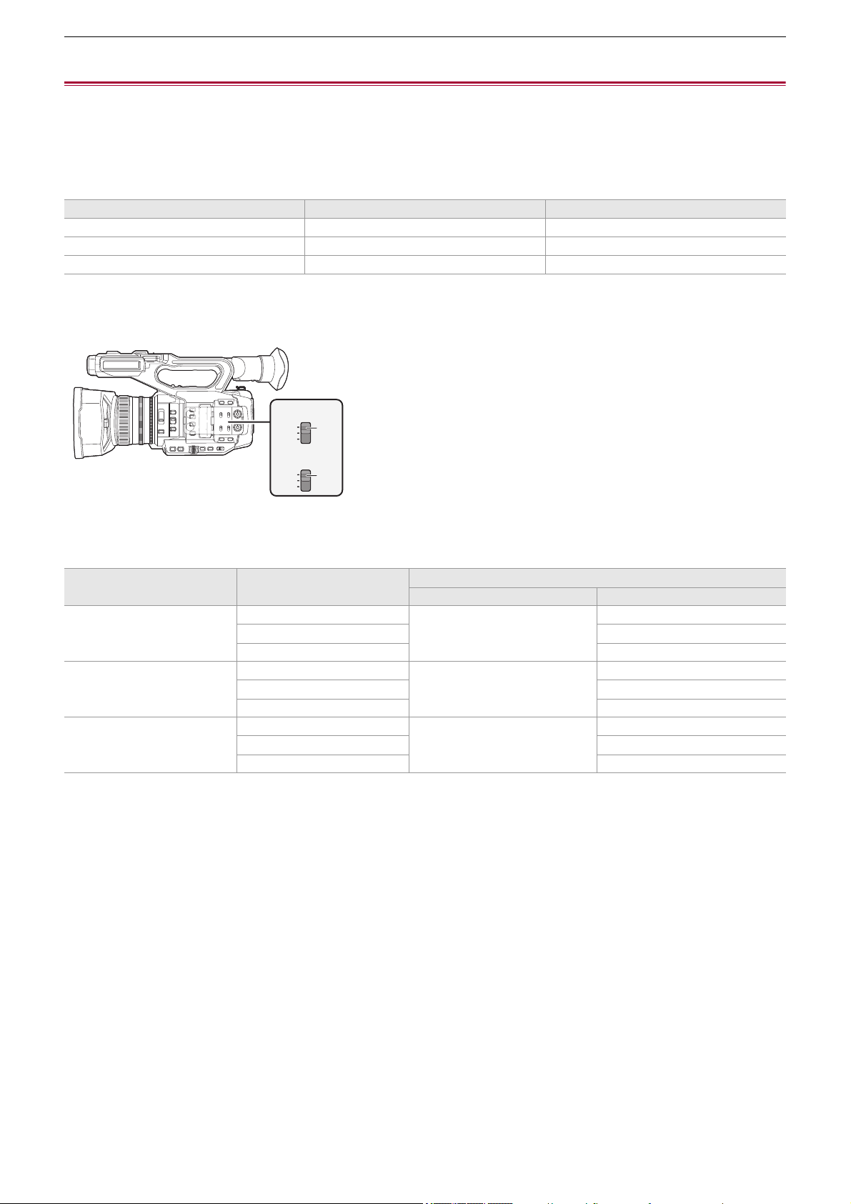
Audio input – Switching the audio input
183
Switching the audio input
≥Using the built-in microphone: 184
≥Using audio equipment/external microphone (XLR, 3-pin): 184
Audio recording format
The audio recording format such as compression format varies depending on the [FILE FORMAT].
Selecting audio input signals
Selects the audio signal to record in the audio channel 1/audio channel 2.
(A) CH1 SELECT switch
(B) CH2 SELECT switch
Confirming audio input setting
The setting for the audio input can be confirmed in the AUDIO screen of the mode check.
• For details about AUDIO screen of the mode check (
ÎAUDIO screen: 258).
[FILE FORMAT] Recording format Sampling rate/bit
[MOV] Linear PCM (LPCM) 48 kHz/24 bit
[MP4] AAC 48 kHz/16 bit
[AVCHD] Dolby Audio
™
48 kHz/16 bit
CH1 SELECT switch setting CH2 SELECT switch setting
Input signal to be recorded
Audio channel 1 Audio channel 2
<INT(L)> <INT(R)> Built-in microphone <L> Built-in microphone <R>
<INPUT1> <AUDIO INPUT1> terminal
<INPUT2> <AUDIO INPUT2> terminal
<INPUT1> <INT(R)> <AUDIO INPUT1> terminal Built-in microphone <R>
<INPUT1> <AUDIO INPUT1> terminal
<INPUT2> <AUDIO INPUT2> terminal
<INPUT2> <INT(R)> <AUDIO INPUT2> terminal Built-in microphone <R>
<INPUT1> <AUDIO INPUT1> terminal
<INPUT2> <AUDIO INPUT2> terminal
INT(L)
INPUT1
INPUT2
CH1
SELECT
INT(R)
INPUT1
INPUT2
CH2
SELECT
(A)
(B)
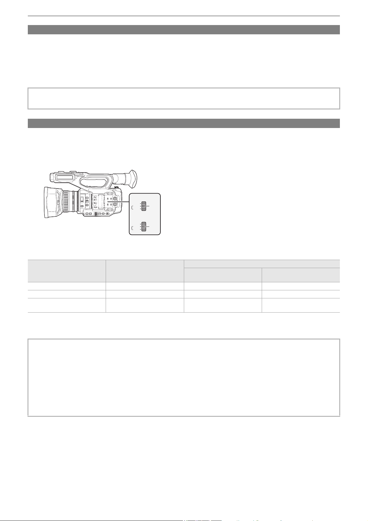
Audio input – Switching the audio input
184
Using the built-in microphone
1
Set the CH1 SELECT switch to the <INT(L)> position.
The audio signals from <L> of the built-in microphone are recorded to audio channel 1.
2
Set the CH2 SELECT switch to the <INT(R)> position.
The audio signals from <R> of the built-in microphone are recorded to audio channel 2.
Using audio equipment/external microphone (XLR, 3-pin)
1
Connect an audio device or an external microphone to the <AUDIO INPUT1>/<AUDIO
INPUT2> terminal.
2
Switch the connected audio input with the <INPUT1>/<INPUT2> switch.
(A) <INPUT1> switch
(B) <INPUT2> switch
*1 Factory setting: [j50dB]
*2 Factory setting: [0dB]
• To decrease the wind noise of the microphone, select the [AUDIO] menu
¨ [REC CH SETTINGS] ¨ [CH1 MIC LOWCUT]/
[CH2 MIC LOWCUT]
¨ [ON].
Connected device
<INPUT1>/<INPUT2> switch
setting
Menu settings (you can set each channel individually)
[INPUT1 MIC LEVEL]/[INPUT2
MIC LEVEL]
*1
[INPUT1 LINE LEVEL]/[INPUT2
LINE LEVEL]
*2
Audio device <LINE> Disabled [4dB], [0dB]
External microphone <MIC> [j40dB], [j50dB], [j60dB] Disabled
External microphone (with power
supply)
<i48V> [j40dB], [j50dB], [j60dB] Disabled
• When using a Unidirectional microphone AG-MC200G (optional), set [INPUT1 MIC LEVEL]/[INPUT2 MIC LEVEL] to
[j50dB].
• After detaching the external microphone (XLR, 3-pin), switch the CH1 SELECT/CH2 SELECT switch to <INT(L)> or
<INT(R)> to set the input signal to the built-in microphone. No audio will be recorded if you continue to record as is.
• When connecting equipment that does not support +48 V power supply, set the <INPUT1>/<INPUT2> switch to
<LINE> or <MIC>. If set to <i48V>, this unit or the connected equipment may malfunction.
• If an abnormality occurs with the +48 V power supply, the power of this unit will turn off.
• Using a phantom microphone shortens the battery time.
• When noise from unconnected terminals is bothersome, set the <INPUT1>/<INPUT2> switch to <LINE>.
LINE
INPUT2
MIC
+48V
LINE
INPUT1
MIC
+48V
(A)
(B)
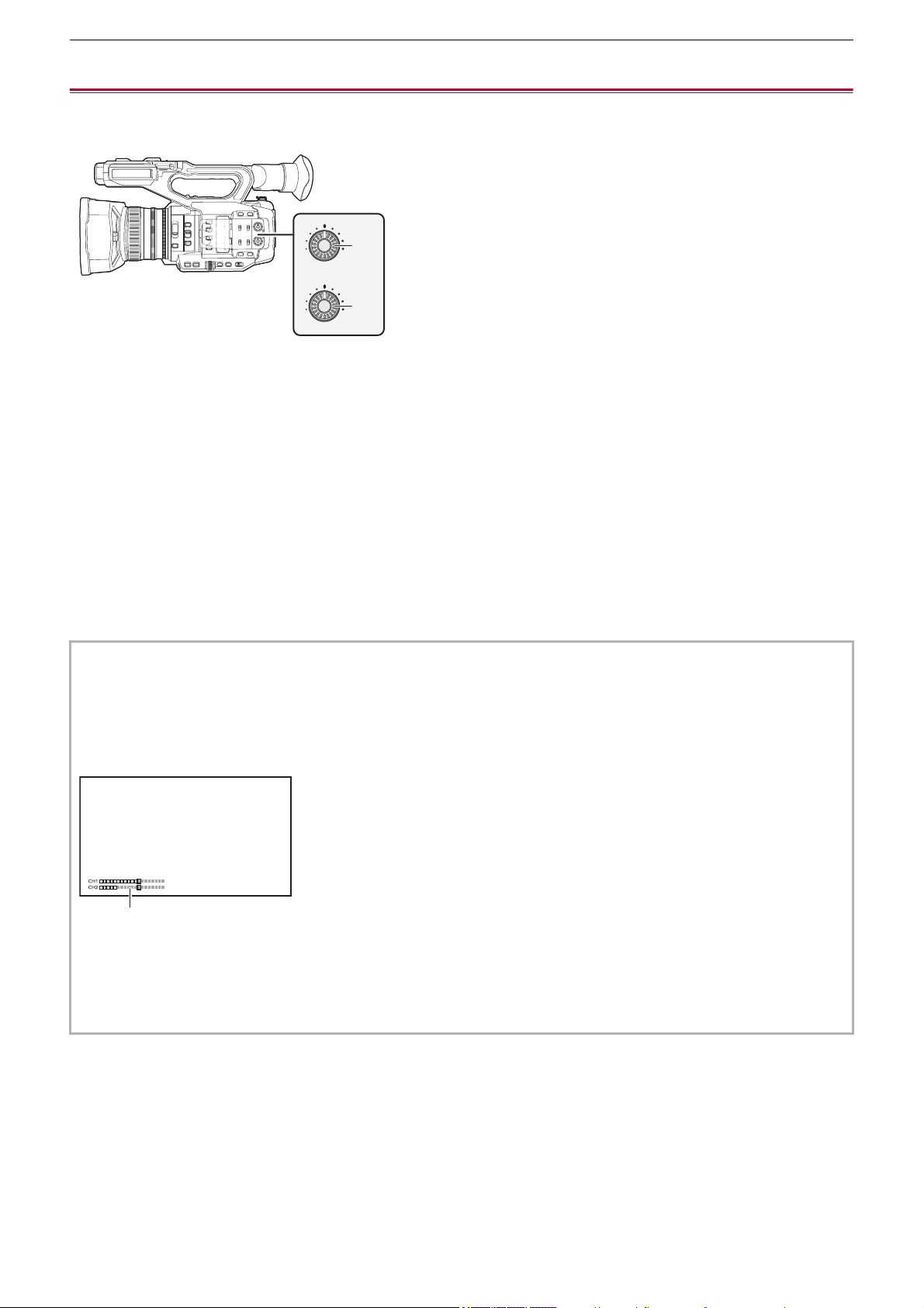
Audio input – Adjusting the audio recording level
185
Adjusting the audio recording level
There are manual adjustment and automatic adjustment as the adjustment method of the audio recording level.
• Audio channel can be individually set.
(A) <AUDIO LEVEL CH1> dial
(B) <AUDIO LEVEL CH2> dial
Automatic adjustment of the recording level
1
Select the [AUDIO] menu ¨ [REC CH SETTINGS] ¨ [CH1 LEVEL]/[CH2 LEVEL] ¨
[AUTO].
Manual adjustment of the recording level
1
Select the [AUDIO] menu ¨ [REC CH SETTINGS] ¨ [CH1 LEVEL]/[CH2 LEVEL] ¨
[MANUAL].
2
Adjust the recording level with <AUDIO LEVEL CH1>/<AUDIO LEVEL CH2> dial.
• When [AUDIO CH1 LEVEL]/[AUDIO CH2 LEVEL] is assigned to the USER button, adjustment method of the recording
level for audio channel 1 and audio channel 2 can be switched between manual and automatic with the USER button.
• When the input level of audio exceeds 0 dB, the level display exceeding 0 dB is displayed in red in the camera image
screen and the audio level meter in the AUDIO screen of the mode check. This is indicating that the input volume is too
high.
Adjust so that the maximum value of the audio level does not exceed 0 dB.
(A) Audio level meter
• To enable the settings in [AUDIO] menu
¨ [REC CH SETTINGS] ¨ [CH1 LIMITER]/[CH2 LIMITER], make the following
settings.
– Select [AUDIO] menu
¨ [REC CH SETTINGS] ¨ [CH1 LEVEL]/[CH2 LEVEL] ¨ [MANUAL]
CH1
AUDIO
LEVEL
CH2
(A)
(B)
(A)

Audio input – Adjusting the audio recording level
186
Recording standard level
The recording standard level can be set.
1
Select the [AUDIO] menu ¨ [REC CH SETTINGS] ¨ [HEAD ROOM] ¨ [12dB]/[18dB]/
[20dB].
Confirming the audio input level
The input level of the audio can be confirmed in the camera image screen and the AUDIO screen of the mode check.

Audio input – Monitoring the audio
187
Monitoring the audio
Audio recorded with the unit can be heard with a speaker or headphones.
Audio is not output from the speaker during shooting.
Setting the output audio
Sets the audio channel and the format to be output from the headphone terminal.
1
Select the [AUDIO] menu ¨ [OUTPUT SETTINGS] ¨ [AUDIO OUT].
2
Select the type of audio.
[CH1]:
Outputs the signal for audio channel 1 as monaural.
[CH2]:
Outputs the signal for audio channel 2 as monaural.
[CH1/2 STEREO]:
Outputs the signals of the audio channel 1 and the audio channel 2 as stereo.
[CH1/2 MIX]:
Mixes the signals of the audio channel 1 and the audio channel 2 and outputs as monaural.
• If [AUDIO OUT] is assigned to the USER button, pressing the USER button switches the audio channel to output and
format.
Toggles [CH1], [CH2], [CH1/2 STEREO], and [CH1/2 MIX] in order each time the USER button is pressed or the USER
button icon is touched.
• Adjust the volume of the headphones and built-in speaker as follows.
– During recording, volume is adjusted with the [ AUDIO MON] of the multi manual function. (
ÎAdjusting headphone
volume: 222
)
– During playback, volume is adjusted with the zoom lever. (
ÎAdjusting the volume during playback: 231)

188
Special recording function
Special recording such as pre-recording or relay recording is possible by setting the menu.
≥Variable frame rate (VFR) recording function/super slow recording function: 189
≥High dynamic range (HDR) recording function [X2]: 193
≥V-Log recording function [X2]: 194
≥Pre-recording: 195
≥Relay recording: 196
≥Simultaneous recording: 197
≥Background recording: 198
≥Dual codec recording [X2]: 200
≥Interval recording: 202
≥IR recording: 203

Special recording function – Variable frame rate (VFR) recording function/super slow recording function
189
Variable frame rate (VFR) recording function/super slow recording
function
It is possible to acquire smooth slow motion or quick motion video by shooting with a different frame rate from the
frame rate to play back.
≥Variable frame rate (VFR): 189
≥Super slow recording function: 191
Variable frame rate (VFR)
Allows the high-speed shooting from 2 fps to maximum of 60 fps.
Setting by selecting the menu
1
In the [SYSTEM] menu ¨ [FREQUENCY]/[FILE FORMAT]/[REC FORMAT], select the
resolution and codec for recording video and the frequency for the reference frame
rate.
The range of the frame rate that can perform high-speed shooting differs depending on the setting.
• For the combinations that can be set (
ÎRecording formats that can be set in variable frame rate recording: 190)
2
Select the [SCENE FILE] menu ¨ [VFR] ¨ [ON].
• This can also be set even with the USER button. (ÎAssigning functions to the USER buttons: 65)
3
Set the frame rate in accordance with the shooting condition in the [SCENE FILE]
menu
¨ [FRAME RATE].
4
Press the REC button.
Variable frame rate recording is started.
Setting with the multidial
1
In the [SYSTEM] menu ¨ [FREQUENCY]/[FILE FORMAT]/[REC FORMAT], select the
resolution and codec for recording video and the frequency for the reference frame
rate.
2
Select the [SCENE FILE] menu ¨ [VFR] ¨ [ON].
3
Turn the multidial to display [ FRAME RATE].
4
Press the multidial.
The frame rate display is highlighted in orange.
5
Turn the multidial to select the frame rate.
6
Press the multidial.
The setting changes to the value displayed and exits.
Press the <EXIT> button to exit without changing the setting.
7
Press the REC button.
Variable frame rate recording is started.
Special recording function – Variable frame rate (VFR) recording function/super slow recording function
190
Recording formats that can be set in variable frame rate recording
• When the [SYSTEM] menu
¨ [FREQUENCY] ¨ [59.94Hz] is set
• When the [SYSTEM] menu ¨ [FREQUENCY] ¨ [50.00Hz] is set
* Recording formats with which slow-motion recording is possible
Frame rates and their effects
[FILE FORMAT]
[MOV]
[REC FORMAT] Available frame rates (fps)
Frame rates (fps) with which audio can be
recorded
[2160-59.94p/420LongGOP 150M]
2 to 60
60[2160-59.94p/HEVC LongGOP 200M]
[2160-59.94p/HEVC LongGOP 100M]
[2160-29.97p/420LongGOP 100M]
*
30
[2160-29.97p/HEVC LongGOP 150M]
2 to 30 30
[2160-29.97p/422LongGOP 150M]
[2160-23.98p/420LongGOP 100M]
*
2 to 60 24
[2160-23.98p/HEVC LongGOP 150M]
*
2 to 30 24
[2160-23.98p/422LongGOP 150M]
*
[1080-59.94p/422LongGOP 100M]
2 to 60
60
[1080-59.94p/422ALL-I 200M]
[1080-29.97p/422LongGOP 50M]
*
30
[1080-29.97p/422ALL-I 100M]
*
[1080-23.98p/422LongGOP 50M]
*
24
[1080-23.98p/422ALL-I 100M]
*
[REC FORMAT] Available frame rates (fps)
Frame rates (fps) with which audio can be
recorded
[2160-50.00p/420LongGOP 150M]
2 to 50
50[2160-50.00p/HEVC LongGOP 200M]
[2160-50.00p/HEVC LongGOP 100M]
[2160-25.00p/420LongGOP 100M]
*
25
[2160-25.00p/HEVC LongGOP 150M]
2 to 25 25
[2160-25.00p/422LongGOP 150M]
[1080-50.00p/422LongGOP 100M]
2 to 50
50
[1080-50.00p/422ALL-I 200M]
[1080-25.00p/422LongGOP 50M]
*
25
[1080-25.00p/422ALL-I 100M]
*
[REC FORMAT] Available frame rates (fps)
[2160-29.97p/420LongGOP 100M] 2 to 28 30 32 to 60
[2160-23.98p/420LongGOP 100M]
2 to 22 24
26 to 60
[2160-23.98p/HEVC LongGOP 150M]
26 to 30
[2160-23.98p/422LongGOP 150M]
[1080-29.97p/422LongGOP 50M]
2 to 28 30 32 to 60
[1080-29.97p/422ALL-I 100M]
[1080-23.98p/422LongGOP 50M]
2 to 22 24 26 to 30
[1080-23.98p/422ALL-I 100M]
[2160-25.00p/420LongGOP 100M]
2 to 23 25 27 to 50[1080-25.00p/422LongGOP 50M]
[1080-25.00p/422ALL-I 100M]
Effect on playback
Quick motion
(The smaller the value is, the faster
the playback becomes.)
Normal
Slow motion
(The larger the value is, the slower
the playback becomes.)
Audio recording No Yes No

Special recording function – Variable frame rate (VFR) recording function/super slow recording function
191
Frame rates during actual recording
There is a slight variation in the frame rate displayed on the screen and the frame rate that is actually recorded.
Recording is with the following frame rates: (frame rate displayed on the screen (frame rate actually recorded))
• When the [SYSTEM] menu
¨ [FREQUENCY] ¨ [59.94Hz] is set
• When the [SYSTEM] menu
¨ [FREQUENCY] ¨ [50.00Hz] is set
Super slow recording function
This allows high-speed shooting of 120 fps/100 fps.
1
In [SYSTEM] menu ¨ [FREQUENCY]/[FILE FORMAT]/[REC FORMAT], select the
resolution, codec, and base frame rate for recording images.
• Select the following items.
2
Select the [SYSTEM] menu ¨ [SUPER SLOW] ¨ [ON].
• This can also be set even with the USER button. (ÎAssigning functions to the USER buttons: 65)
3
Press the REC button.
Super slow recording starts.
Frame rate and effect
The slow motion effect during playback changes depending on the frame rate of the [REC FORMAT].
Frame rates during actual recording
When [SYSTEM] menu
¨ [FREQUENCY] ¨ [59.94Hz], there is a slight variation in the frame rate of super slow recording and
the frame rate that is actually recorded.
2fps (2.00 fps) 12fps (11.99 fps)
15fps (14.99 fps) 20fps (19.98 fps)
22fps (21.93 fps) 24fps (23.98 fps)
26fps (26.22 fps) 28fps (27.97 fps)
30fps (29.97 fps) 32fps (32.11 fps)
34fps (33.72 fps) 36fps (35.96 fps)
45fps (44.96 fps) 48fps (47.95 fps)
60fps (59.94 fps)
2fps (2.00 fps) 12fps (12.50 fps)
21fps (20.83 fps) 23fps (23.15 fps)
25fps (25.00 fps) 27fps (27.17 fps)
30fps (30.00 fps) 37fps (36.76 fps)
50fps (50.00 fps)
[FREQUENCY] [FILE FORMAT] [REC FORMAT]
[59.94Hz]
[MOV]
[1080-59.94p/422LongGOP 100M]
[1080-29.97p/422LongGOP 50M]
[1080-23.98p/422LongGOP 50M]
[50.00Hz]
[1080-50.00p/422LongGOP 100M]
[1080-25.00p/422LongGOP 50M]
Frame rate of [REC FORMAT] Slow motion effect during playback
59.94p, 50.00p 1/2 speed
29.97p, 25.00p 1/4 speed
23.98p 1/5 speed
Screen display Frame rates during actual recording
[S.SLOW120] 119.88 fps

Special recording function – Variable frame rate (VFR) recording function/super slow recording function
192
(Variable frame rate recording/super slow recording)
• In the following cases, this cannot be set.
– When set to an item that does not support [FILE FORMAT] or [REC FORMAT]
– When using the face detection/tracking AE&AF function
• The [CAMERA] menu
¨ [SW MODE] ¨ [AF SPEED] and [AF SENSITIVITY] will operate in [0].
• The [RECORDING] menu
¨ [TC/UB] ¨ [FREE/REC RUN] is fixed to [REC RUN].
• The following functions are canceled.
– Dynamic range stretcher function (
ÎDynamic range stretcher function: 214)
– Flash band compensation function(ÎFlash band compensation (FBC) function: 219)
– Pre-recording (
ÎPre-recording: 195)
– [2 SLOTS FUNC.] (
ÎRelay recording: 196 to Dual codec recording [X2]: 200)
– Interval recording (ÎInterval recording: 202)
– [HYBRID O.I.S.] (
ÎSwitching enable/disable of the hybrid optical image stabilizer function: 213)
• It is not possible to adjust the shutter speed to a value slower than the limit imposed by the frame rate used for variable
frame rate recording/super slow recording.
• The recording is paused when ten hours has past from the time the recording was started. The recording is automatically
resumed after few seconds.
– When performing high-speed (slow motion) shooting, the recording time will be shorter than 10 hours depending on the
ratio of the frame rate of the recording format and the variable frame rate. The recording will stop in 5 hours when the
frame rate of [REC FORMAT] is set to 23.98p and the [SCENE FILE] menu
¨ [FRAME RATE] is set to [48fps].
• It may take time to stop recording even if recording is stopped right after recording is started.
When set to a 59.94p recording format and [SCENE FILE] menu ¨ [FRAME RATE] is set to [2fps], recording continues for
up to 30 seconds so that the clip length after recording reaches 1 second.
• There are recording functions that cannot be used simultaneously. (
ÎRecording function that cannot be used
simultaneously: 297
)
(Variable frame rate recording)
• Audio cannot be recorded with the variable frame rate recording. Audio can be recorded, however, if the set frame rate is
the same frame rate as [REC FORMAT].
• When [SUPER SLOW] is [ON], variable frame rate recording cannot be set.
• The screen may be disrupted or become dark when the frame rate setting is changed.
• The frame rate cannot be changed while recording.
• When recording at a low frame rate setting, it may be difficult for the camera to keep up with changes in the images. If this
occurs, use the manual settings for the iris, focus, and white balance mode.
(Super slow recording)
• Audio cannot be recorded with the super slow recording.
• When [SUPER SLOW] is [ON], the unit will restart after the following operation.
– If changed to an item that does not support [FILE FORMAT] or [REC FORMAT]

Special recording function – High dynamic range (HDR) recording function [X2]
193
High dynamic range (HDR) recording function [X2]
It is possible to record images with the wide dynamic range of the HLG method.
1
Select the [SCENE FILE] menu ¨ [GAMMA MODE SEL] ¨ [HLG].
[HDR] is displayed in the camera image screen.
Note regarding the [KNEE SETTING] during HDR recording
When [GAMMA MODE SEL] is set to [HLG], the following [KNEE SETTING] items become available:
[SCENE FILE] menu
¨ [KNEE SETTING]
[HLG KNEE SW]:
Enables/disables the operation of knee for HLG.
[HLG KNEE POINT]:
Sets the position of the knee point for HLG.
[HLG KNEE SLOPE]:
Sets the inclination of knee for HLG.
Note regarding HDR image output
Settings can be made with the following menus.
Output is either High Dynamic Range (HDR) or Standard Dynamic Range (SDR).
• <SDI OUT> terminal:
[VIDEO OUT/LCD/VF] menu
¨ [SDI SETTING] ¨ [SDI OUT HDR]
• <HDMI> terminal:
[VIDEO OUT/LCD/VF] menu
¨ [HDMI SETTING] ¨ [HDMI OUT HDR]
• Viewfinder, LCD monitor:
[VIDEO OUT/LCD/VF] menu
¨ [VF] ¨ [LCD/VF HDR]
• The following functions cannot be set.
– [SCENE FILE] menu
¨ [KNEE SETTING] ¨ [KNEE MODE]/[KNEE POINT]/[KNEE SLOPE]
– [SCENE FILE] menu
¨ [WHITE CLIP SETTING]/[DRS]/[DRS EFFECT DEPTH]
– [VIDEO OUT/LCD/VF] menu
¨ [SDI SETTING] ¨ [SDI OUT ZEBRA]
– [VIDEO OUT/LCD/VF] menu ¨ [HDMI SETTING] ¨ [HDMI OUT ZEBRA]
– [VIDEO OUT/LCD/VF] menu
¨ [EI ASSIST] ¨ [ZEBRA]/[ZEBRA1 DETECT]/[ZEBRA2 DETECT]/[ZEBRA2]

Special recording function – V-Log recording function [X2]
194
V-Log recording function [X2]
It is possible to record with a rich range of latitude for more expressive images.
• The recorded images are suited to color grading.
1
Select the [SCENE FILE] menu ¨ [GAMMA MODE SEL] ¨ [V-Log].
[VLog] is displayed in the camera image screen.
Note regarding V-Log image output
Settings can be made with the following menus.
The images are output with settings suited to V-Log images or previews.
• <SDI OUT> terminal:
[VIDEO OUT/LCD/VF] menu ¨ [SDI SETTING] ¨ [SDI OUT V-Log]
• <HDMI> terminal:
[VIDEO OUT/LCD/VF] menu
¨ [HDMI SETTING] ¨ [HDMI OUT V-Log]
• Viewfinder, LCD monitor:
[VIDEO OUT/LCD/VF] menu
¨ [VF] ¨ [LCD/VF V-Log]
• The following functions cannot be set.
– [CAMERA] menu
¨ [SW MODE] ¨ [IR REC]
– [SCENE FILE] menu
¨ [MASTER DTL]/[DTL CORING]/[V.DTL LEVEL]/[SKIN TONE DTL.]/[SKIN DTL EFFECT]/
[CHROMA LEVEL]/[CHROMA PHASE]/[MATRIX]/[COLOR CORRECTION]/[MASTER PED]/[GAMMA SETTING]/[KNEE
SETTING]/[WHITE CLIP SETTING]/[DRS]/[DRS EFFECT DEPTH]
– [VIDEO OUT/LCD/VF] menu
¨ [SDI SETTING] ¨ [SDI OUT ZEBRA]
– [VIDEO OUT/LCD/VF] menu ¨ [HDMI SETTING] ¨ [HDMI OUT ZEBRA]
– [VIDEO OUT/LCD/VF] menu
¨ [EI ASSIST] ¨ [ZEBRA]/[ZEBRA1 DETECT]/[ZEBRA2 DETECT]/[ZEBRA2]
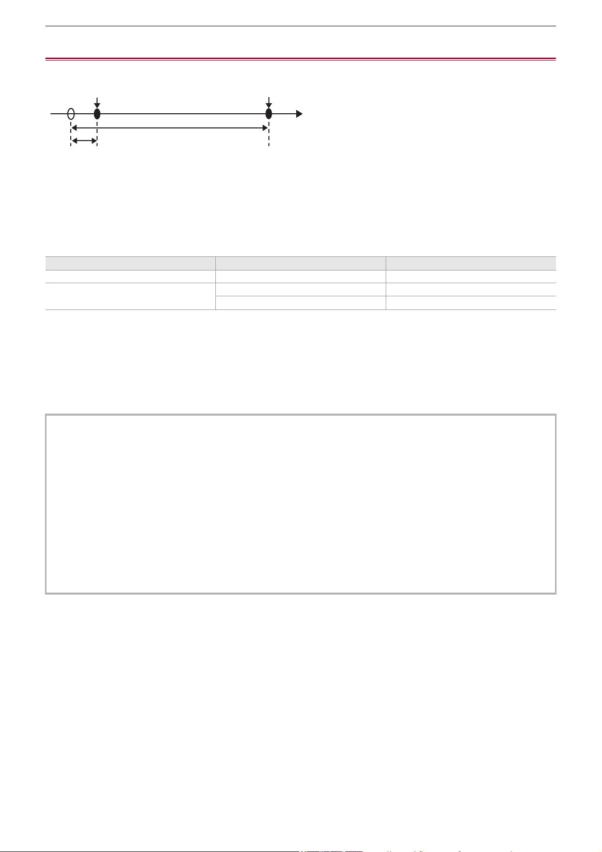
Special recording function – Pre-recording
195
Pre-recording
Records the video and audio from specific time before the operation to start the recording.
(A) Operation to start recording
(B) Operation to stop recording
(C) (Time)
(D) Pre-recording time
(E) Actual recording time
The pre-recording time varies depending on the setting of the [SYSTEM] menu
¨ [FILE FORMAT]/[REC FORMAT].
1
Select the [RECORDING] menu ¨ [PRE REC] ¨ [ON].
[P] is displayed in the recording status display of the camera image screen.
• You can also either press the USER button assigned to [PRE REC] or touch the USER button icon to switch enable/
disable of [PRE REC].
2
Press the REC button.
Pre-recording time [FILE FORMAT] [REC FORMAT]
Approx. 5 seconds [MOV], [MP4] UHD recording format
Approx. 10 seconds
[MOV], [MP4] FHD recording format
[AVCHD] All
• Aim the unit at the subject beforehand.
• The video and audio may not be able to record for specific time before in following cases.
– Immediately after turning on the power
– Immediately after opening the menu
– Immediately after the memory card is inserted
– Immediately after playing back the recorded video
– Immediately after closing the thumbnail screen
– During the time from recording stop until completion of writing to the memory card
• When [PRE REC] is set to [ON], the [RECORDING] menu
¨ [TC/UB] ¨ [FREE/REC RUN] is fixed to [FREE RUN].
• The pre-recording is canceled once when 3 hours has past without starting the recording.
• Pre-recording cannot be performed if the remaining recording capacity of the memory card is less than 1 minute.
• There are recording functions that cannot be used simultaneously. (
ÎRecording function that cannot be used
simultaneously: 297
)
(A)
(D)
(E)
(B)
(C)

Special recording function – Relay recording
196
Relay recording
When inserting memory cards into the 2 card slots, recording can continue on the second memory card if the remaining
recording capacity of the other memory card is exhausted.
(A) Card slot 1
(B) Card slot 2
(C) Start recording
(D) Pause
(1) During recording
(2) Automatically switch the recording target card slot
(3) Replace with a different recordable memory card
1
Select the [RECORDING] menu ¨ [2 SLOTS FUNC.] ¨ [RELAY REC].
[RELAY] is displayed in the 2 slot function display of the camera image screen.
A slanted line is displayed on the [RELAY] display when the relay recording is not possible, such as when a memory card
is not inserted in either of the 2 card slots.
2
Press the REC button.
• The recording target switches to another memory card when the remaining recording capacity of one of the memory
cards is exhausted during recording and relay recording starts. The number of the card slot that became the recording
target is displayed with black and white inverted. Recording can be performed on 3 or more memory cards. Replace the
memory card with no more remaining recording capacity after the recording target has switched.
• To change the recording target card slot before starting the recording, press the USER button or touch the USER button
icon to which [SLOT SEL] is assigned. This will not operate during recording. (
ÎAssigning functions to the USER
buttons: 65
)
• It may take some time to recognize the memory card when the memory card is inserted. When recording to 3 or more
memory cards by replacing a memory card while recording, replace the memory card with recording capacity sufficiently left
on the memory card that is recording.
• The recording target cannot be switched when the remaining recording capacity of the relay memory card is less than
1minute.
• After relay recording, a message about the remaining card capacity is displayed. Replace the memory card that has run out
of capacity.
• The maximum continuous recording time for relay recording is 10 hours.
• The recording is stopped once when the recording time of relay recording exceeds 10 hours. The recording is automatically
resumed after few seconds.
• There are recording functions that cannot be used simultaneously. (
ÎRecording function that cannot be used
simultaneously: 297
)
(1)
(1)
(3)
(1)
(A)
(B)
(C) (D)
(2)
(2)

Special recording function – Simultaneous recording
197
Simultaneous recording
Insert memory cards into 2 card slots to record the same video onto 2 memory cards.
(A) Memory card recording time
(B) Card slot 1
(C) Card slot 2
(D) Start recording
(E) End recording
(F) End recording (no remaining space)
(1) A clip
(2) Stand-by
(3) B clip
(4) C clip
1
Select the [RECORDING] menu ¨ [2 SLOTS FUNC.] ¨ [SIMUL REC].
[SIMUL] is displayed in the 2 slot function display of the camera image screen.
A slanted line is displayed on the [SIMUL] display when simultaneous recording is not possible, such as when a memory
card is not inserted in either of the 2 card slots.
2
Press the REC button.
• The simultaneous recording will stop when the remaining recording capacity of one of the memory cards is exhausted.
A slanted line is displayed in the [SIMUL] display when simultaneous recording is not possible.
To start the simultaneous recording again, replace the memory card that has run out of the recording capacity with
another memory card, and then press the REC button.
• When the REC button is pressed without replacing the memory card, standard recording is performed to the memory
card with remaining recording capacity.
• Use of memory cards with the same Speed Class or capacity for simultaneous recording is recommended.
The recording may stop due to insufficient speed when memory cards with different Speed Classes or capacities are used.
If the recording is stopped, the video right before stopping may become invalid recording.
• Start the recording after both of the 2 memory cards have been recognized. When the recording starts before both memory
cards are recognized, the unit performs standard recording on one of the memory cards that has been recognized. The unit
confirms the status of the memory card every time the recording is completed. If both cards are recognized at that time, it
will perform the simultaneous recording from the next recording.
• When recording to one of the memory cards stops due to a recording error during simultaneous recording, recording to the
other memory card continues.
• If there is remaining recording capacity on one of the memory cards after completing the simultaneous recording, the
memory card with remaining recording capacity automatically becomes the recording target. Standard recording will start
when the REC button is pressed.
• Standard recording is performed when only one memory card is inserted even if the unit is set to simultaneous recording.
• Once the simultaneous recording is completed, [DEL LAST CLIP] assigned to the USER button will not operate.
• For the folder name and the file name when performing simultaneous recording in MOV format/MP4 format (
ÎFolder name
of the MOV format/MP4 format video data: 51
, File name of the MOV format/MP4 format video data: 52).
• There are recording functions that cannot be used simultaneously. (
ÎRecording function that cannot be used
simultaneously: 297
)
(B)
(D)
(F)
(A)
(D)
(E)
(C)
(1)
(1)
(2)
(2)
(3)
(3) (4)
Special recording function – Background recording
198
Background recording
If the memory cards are inserted into 2 card slots, set the background recording mode and then press the REC button to start
recording simultaneously on card slot 1 and card slot 2. On card slot 1, recording can be repeatedly started and stopped as
necessary by operating the REC button. On card slot 2, the recording operation continues as background recording.
By performing background recording on card slot 2, you will not miss important scenes while recording is stopped.
(A) Memory card recording time
(B) REC button operations
(C) Button operation for background recording stop
*
(D) Card slot 1 (Main recording)
(E) Card slot 2 (Background recording)
(F) REC
(G) REC PAUSE
(H) REC STOP (No remaining space on card slot 1)
(I) Continues recording to card slot 2
(1) A clip
(2) Stand-by
(3) B clip
* USER button assigned to [BACKGR PAUSE]
Starting background recording
1
Select the [SYSTEM] menu ¨ [FILE FORMAT] ¨ [MOV].
2
Select the [RECORDING] menu ¨ [2 SLOTS FUNC.] ¨ [BACKGR REC].
[BACKGR] is displayed in the 2 slot function display of the camera image screen.
A slanted line is displayed on the [BACKGR] display when background recording is not possible, such as when a memory
card is not inserted in the card slot 2.
3
Press the REC button.
Recording starts simultaneously on card slot 1 and card slot 2.
Start or stop recording on card slot 1 with REC button operations.
On card slot 2, the recording operation continues as background recording.
(1)
(1)
(2) (3)
(B)
(C)
(D)
(E)
(F)
(F)
(G) (F) (H)
(G)
(I)
(A)
Special recording function – Background recording
199
Ending background recording
1
Press and hold the USER button to which [BACKGR PAUSE] is assigned for
approximately 5 seconds or touch and hold the USER button icon for approximately
5 seconds and release.
The background recording stops on card slot 2.
The background recording on card slot 2 can also be stopped by pressing and holding the <EXIT> button for approximately
5 seconds.
• Records on both card slot 1 and card slot 2 in the format set in the [SYSTEM] menu.
• Background recording cannot be performed in the following cases.
– When [SYSTEM] menu
¨ [FILE FORMAT] is set to other than [MOV]
– When [SYSTEM] menu
¨ [REC FORMAT] is UHD
• The lighting status of the tally lamps changes according to start or stop of recording on card slot 1.
• Time code is fixed to free run.
• Control of recording operation of the external equipment (such as recorder) connected to the <SDI OUT> terminal
*
and the
<HDMI> terminal is linked to the start/stop recording of the card slot 1.
• In the background recording mode, the USER button assigned to [DEL LAST CLIP] does not work.
• The memory card in card slot 1 can be replaced even while background recording is performed on card slot 2 if recording
on card slot 1 is stopped.
• In the background recording mode, standard recording can be performed on card slot 1 if a memory card for recording is not
inserted in card slot 2 or the remaining recording capacity of the memory card in card slot 2 has run out.
• When the capacity in the memory card in card slot 2 runs out during recording, background recording will not start
automatically even if you replace the memory card in card slot 2.
• There are recording functions that cannot be used simultaneously. (
ÎRecording function that cannot be used
simultaneously: 297
)
* When using , the <SDI OUT> terminal can be used.
• The background recording on card slot 2 cannot end while recording is performed on card slot 1. End the background
recording while recording is stopped on card slot 1.
• The background recording on card slot 2 ends in the following cases.
– When the power is turned off
– When the remaining recording capacity of the memory card has run out
– When an error has occurred when writing to the memory card

Special recording function – Dual codec recording [X2]
200
Dual codec recording [X2]
You can make main and sub recordings simultaneously in separate [REC FORMAT] settings.
Sub recording records scenes in a picture quality lower than that of the [REC FORMAT] setting for main recording.
(A) Card slot 1 (main recording)
(B) Card slot 2 (sub recording)
(C) Start recording
(D) Pause
(1) Recording
(2) Recording in low picture quality
1
Select [SYSTEM] menu ¨ [FILE FORMAT] ¨ [MOV].
2
Set [REC FORMAT] and [DUAL CODEC SETTING].
[SYSTEM] menu ¨ [REC FORMAT]
[RECORDING] menu
¨ [DUAL CODEC SETTING]
• For details about the setting items (
ÎNote regarding [REC FORMAT] and [DUAL CODEC SETTING] which
can be set with dual codec recording: 201
)
• The settings for clips recorded on the sub recording side will be as follows:
– Recording is in the MOV format.
– Recording is at FHD (1920×1080)
– The recorded frame rate will be the same as the recording format on the main recording side.
3
Select [RECORDING] menu ¨ [2 SLOTS FUNC.] ¨ [DUAL CODEC REC].
Either [DUAL 50M] or [DUAL 8M] is displayed in the 2-slot function display on the camera image screen.
When dual codec recording is not possible, such as when a memory card has not been inserted in card slot 2,
the display for [DUAL 50M]/[DUAL 8M] will appear crossed out.
4
Press the REC button.
• Recording cannot start if there is no recordable memory card in card slot 1.
• Normal recording is performed to card slot 1 in the following cases:
– There is no recordable memory card in card slot 2
– There is no remaining space on the memory card in card slot 2
• Recording on the main recording side does not stop even if there is an error with the memory card on the sub recording
side.
Recording stops if there is an error with the memory card on the main recording side.
• If clips are automatically divided during recording on the main recording side, dividing occurs on the sub recording side at
the same timing as on the main recording side. (
ÎRecording time of the memory card: 48)
• Dual codec recording is not possible in the following cases:
– When [SYSTEM] menu
¨ [FILE FORMAT] is set to other than [MOV]
– When [SYSTEM] menu
¨ [REC FORMAT] is set to an item that does not support dual codec recording (ÎNote
regarding [REC FORMAT] and [DUAL CODEC SETTING] which can be set with dual codec recording: 201
)
• The following USER button functions are not available when dual codec recording is set:
– [REC CHECK]
– [DEL LAST CLIP]
– [SLOT SEL]
• There are recording functions that cannot be used simultaneously. (
ÎRecording function that cannot be used
simultaneously: 297)
(A)
(B)
(C) (D)
(1)
(2)

Special recording function – Dual codec recording [X2]
201
Note regarding [REC FORMAT] and [DUAL CODEC SETTING] which can be set with
dual codec recording
• When [DUAL CODEC SETTING] is set to [FHD 50Mbps]
• When [DUAL CODEC SETTING] is set to [FHD 8Mbps]
[FREQUENCY] [REC FORMAT] Bit rate of sub recording
[59.94Hz] [2160-29.97p/420LongGOP 100M], [2160-23.98p/420LongGOP 100M]
50 Mbps
[50.00Hz] [2160-25.00p/420LongGOP 100M]
[FREQUENCY] [REC FORMAT] Bit rate of sub recording
[59.94Hz]
[2160-29.97p/420LongGOP 100M], [2160-23.98p/420LongGOP 100M],
[1080-59.94p/422ALL-I 200M], [1080-59.94p/422LongGOP 100M],
[1080-59.94i/422ALL-I 100M], [1080-29.97p/422ALL-I 100M],
[1080-23.98p/422ALL-I 100M]
8 Mbps
[50.00Hz]
[2160-25.00p/420LongGOP 100M], [1080-50.00p/422ALL-I 200M],
[1080-50.00p/422LongGOP 100M], [1080-50.00i/422ALL-I 100M],
[1080-25.00p/422ALL-I 100M]
• To set [DUAL CODEC SETTING], make the following menu settings beforehand:
– [SCENE FILE] menu
¨ [VFR] ¨ [OFF]
– [RECORDING] menu
¨ [REC FUNCTION] ¨ [REC MODE] ¨ [NORMAL]
– [NETWORK] menu
¨ [NETWORK FUNC] ¨ [OFF]
– [SYSTEM] menu ¨ [FILE FORMAT] ¨ [MOV]
– [SYSTEM] menu
¨ [SUPER SLOW] ¨ [OFF]
• To set [DUAL CODEC SETTING] to [FHD 50Mbps], make the following menu setting beforehand:
– In [SYSTEM] menu ¨ [REC FORMAT], set to the UHD (3840×2160) item
Special recording function – Interval recording
202
Interval recording
The unit will record 1 frame at each set time interval.
It is possible to record a short clip of a long slow-moving scene, such as a sunset, by recording with intervals between frames.
(A) 1 frame recording
(B) (Time)
(C) Time set in [INTERVAL TIME]
1
Select the [SYSTEM] menu ¨ [FILE FORMAT] ¨ [MOV].
2
Select the [RECORDING] menu ¨ [REC FUNCTION] ¨ [REC MODE] ¨ [INTERVAL].
[INTRVL] is displayed in the special recording function display of the camera image screen.
3
Set the time in the [RECORDING] menu ¨ [REC FUNCTION] ¨ [INTERVAL TIME].
4
Press the REC button.
• [I-REC] is displayed in red in the special recording function display of the camera image screen.
• The unit will repeat the operation of one frame recording at set time interval.
• To stop recording, press the REC button.
• Set [NORMAL] in the [RECORDING] menu
¨ [REC FUNCTION] ¨ [REC MODE] to clear the setting.
• In the following cases, [REC MODE] is fixed to [NORMAL].
– When [SYSTEM] menu
¨ [FILE FORMAT] is set to [MP4] or [AVCHD]
• The setting is cleared when the power is turned off.
• Audio is not recorded.
• Recorded data (data recorded until recording was stopped) is included in 1 clip.
• The [RECORDING] menu
¨ [TC/UB] ¨ [FREE/REC RUN] is fixed to [REC RUN].
• The [RECORDING] menu
¨ [TC/UB] ¨ [DF/NDF] is fixed to [NDF].
• (For the )
The [VIDEO OUT/LCD/VF] menu
¨ [SDI SETTING] ¨ [SDI REC REMOTE] and the [VIDEO OUT/LCD/VF] menu ¨ [HDMI
SETTING]
¨ [HDMI REC REMOTE] do not work.
(For the )
The [VIDEO OUT/LCD/VF] menu ¨ [HDMI OUT] ¨ [HDMI REC REMOTE] does not work.
• When [REC MODE] is set to [INTERVAL], the [DEL LAST CLIP] assigned to the USER button does not work.
• If the length of the clip is less than 3 seconds when the recording is stopped, the image of the final frame will be recorded to
make the length of the clip to 3 seconds.
• Depending on the light source and the scene being recorded, color hue and focus may not be automatically set. In case
such as this, try adjusting manually. (
ÎFocusing (manual focus): 156, Adjusting the white and black balance: 163)
• When recording for long periods, it is recommended to connect to the AC adaptor for recording.
• The recording is stopped once when the length of the clip exceeds 10 hours in the interval recording. The recording is
automatically resumed after few seconds.
• There are recording functions that cannot be used simultaneously. (
ÎRecording function that cannot be used
simultaneously: 297
)
(A) (A) (A)
(B)
(C) (C)

Special recording function – IR recording
203
IR recording
A night time shooting using the IR light (commercially-available) can be performed.
Assigning [IR REC] to the USER button
1
Select the [CAMERA] menu ¨ [USER SW] ¨ [USER1] to [USER14] ¨ [IR REC].
Set so enable/disable of the IR recording can be switched with a USER button.
Performing IR recording
1
Press the USER button to which [IR REC] is assigned or touch the USER button icon.
The unit will enter the IR recording mode.
• The following happens in the IR recording mode:
– [IR] is displayed on the camera image screen.
– Iris is automatically adjusted.
2
Press the REC button.
IR recording is started.
• In the following case, this cannot be set.
– When using the face detection/tracking AE&AF function
– (For the )
When the [SCENE FILE] menu
¨ [GAMMA MODE SEL] ¨ [V-Log] is set
• This can also be set with the [CAMERA] menu
¨ [SW MODE] ¨ [IR REC].
• It is recommended to use a tripod.
• It takes longer to focus with auto focus in dark locations.
• You can record a clear image by positioning the center area of the screen over the subject.
• Focus values may not be displayed correctly in IR recording mode.
• It is also possible to change the color in which images are recorded in [IR REC COLOR]. (
Î[IR REC COLOR]: 83)

204
Convenient shooting functions
≥Zebra patterns display: 205
≥Displaying the marker: 206
≥Focus assist function: 208
≥Face detection/tracking AE&AF function: 211
≥Optical image stabilizer function: 213
≥Dynamic range stretcher function: 214
≥Time stamp function: 215
≥Waveform monitor function: 216
≥Digital zoom function: 217
≥Level gauge: 218
≥Flash band compensation (FBC) function: 219
≥Operation icon screen display: 220
≥Multi manual function: 221
Convenient shooting functions – Zebra patterns display
205
Zebra patterns display
The unit can display 2 types of zebra patterns to the output image from the LCD monitor.
1
Select the [VIDEO OUT/LCD/VF] menu ¨ [EI ASSIST] ¨ [ZEBRA] ¨ [ON].
• You can also either press the USER button assigned to [ZEBRA] or touch the USER button icon to display the zebra
pattern and switch display/hide.
This changes depending on the [VIDEO OUT/LCD/VF] menu
¨ [EI ASSIST] ¨ [ZEBRA] settings.
Setting the detection level
1
Set each item in the [VIDEO OUT/LCD/VF] menu ¨ [EI ASSIST].
[ZEBRA1 DETECT]:
Sets the detection level of zebra pattern 1.
[50%]…[105%]
[ZEBRA2 DETECT]:
Sets the detection level of zebra pattern 2.
[50%]…[105%]
[ZEBRA2]:
Switches enable/disable of zebra pattern 2.
[ON], [OFF]
Display area of the zebra pattern
The display area of the zebra pattern varies depending on the [VIDEO OUT/LCD/VF] menu
¨ [EI ASSIST] setting.
(A) [ZEBRA2]
(B) [ZEBRA2 DETECT]
(C) [ZEBRA1 DETECT]
(1) [ON]
(2) [OFF]
[ZEBRA] settings Operation when the USER button is pressed
[MOMENT] Displays the zebra pattern for approximately 5 seconds.
[ON], [OFF] Switches display/hide of the zebra pattern.
• The zebra pattern cannot be recorded.
• To record video with less overexposure, manually adjust the shutter speed and brightness (iris/gain) so that the zebra
pattern is no longer displayed. (
ÎIris: 151, Gain: 152, Setting the shutter speed: 159)
• (For the )
The zebra pattern is not displayed when the [SCENE FILE] menu
¨ [GAMMA MODE SEL] ¨ [HLG]/[V-Log] is set.
[105%]
[0%]
(A)
(B)
(C)
(1) (2)

Convenient shooting functions – Displaying the marker
206
Displaying the marker
Displaying the center marker
A center marker can be displayed.
1
Select the type of the center marker in the [VIDEO OUT/LCD/VF] menu ¨ [MARKER]
¨ [CENTER MARKER].
• The center marker is not displayed when [OFF] is selected.
Displaying the safety zone marker
A safety zone marker can be displayed.
1
Select the type of the frame in the [VIDEO OUT/LCD/VF] menu ¨ [MARKER] ¨
[SAFETY MARKER].
• The safety zone marker is not displayed when [OFF] is selected.
[1] [2]
[3] [4]
[1] [2]

Convenient shooting functions – Displaying the marker
207
Displaying frame marker
A frame marker can be displayed.
1
Select the angle of the view in the [VIDEO OUT/LCD/VF] menu ¨ [MARKER] ¨
[FRAME MARKER].
• The frame marker is not displayed when [OFF] is selected.
[4:3] [13:9] [14:9]
[16:9] [17:9] [1.85:1]
[2.35:1]
• Markers cannot be recorded.
• Markers are not displayed when the enlarged display function of the focus assist function is enabled.
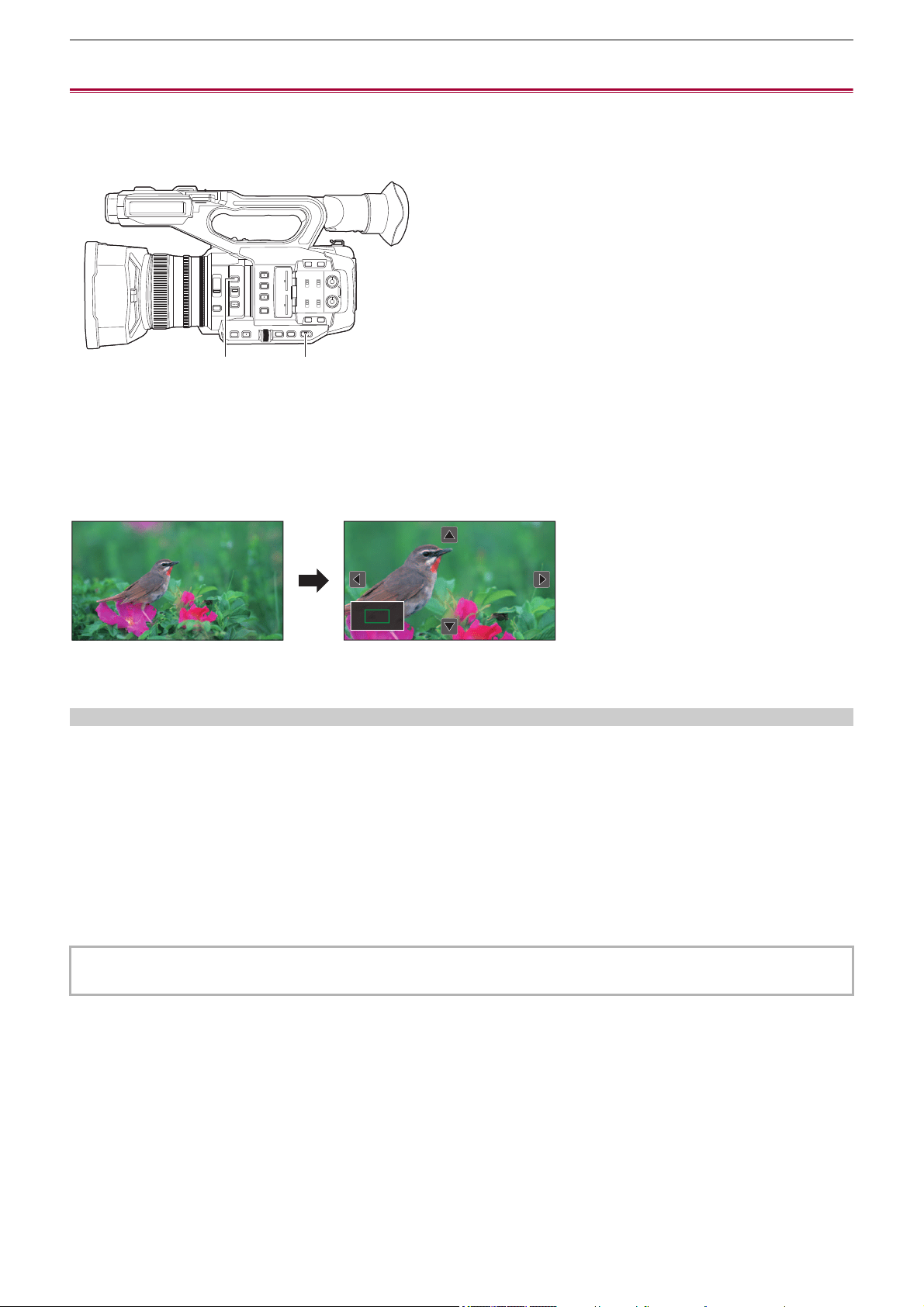
Convenient shooting functions – Focus assist function
208
Focus assist function
The focus assist function enables you to focus the target easily.
The recording image on the LCD monitor and the viewfinder can be displayed enlarged, or the focused area can be visually
enhanced.
(A) <FOCUS ASSIST> button
(B) <AUTO/MANU> switch
Enlarged display function
Center of the recording image is displayed enlarged to make it easier to focus.
(A) Normal display
(B) Enlarged display
Using the enlarged display function
Set so enable/disable of the enlarged display function can be switched with a <FOCUS ASSIST> button.
1
Set the <AUTO/MANU> switch to <MANU> to switch to manual mode.
2
Set the <FOCUS A/M/¶> switch to <M> to switch to manual focus mode.
3
Select [VIDEO OUT/LCD/VF] menu ¨ [FOCUS ASSIST] ¨ [FOCUS ASSIST SW] ¨
[EXPAND] or [EXPAND&PEAKING].
4
Press the <FOCUS ASSIST> button.
Press the <FOCUS ASSIST> button again to return to the normal display.
• The operation in Step 4 can also be done with the USER button/USER button icon that has been assigned [FOCUS
ASSIST]. (
ÎAssigning functions to the USER buttons: 65)
(A) (B)
(A) (B)

Convenient shooting functions – Focus assist function
209
Setting the mode for enlarged display function
1
Select the mode for the enlarged display function in the [VIDEO OUT/LCD/VF] menu
¨ [FOCUS ASSIST] ¨ [EXPAND MODE].
[10SEC]:
Disables the enlarged display function after 10 seconds have elapsed.
[HOLD]:
Enables the enlarged display function until the <FOCUS ASSIST> button is pressed again.
[UNTIL REC]:
Enables the enlarged display function until starting the recording operation.
Setting the enlargement rate
1
Select the enlargement rate in the [VIDEO OUT/LCD/VF] menu ¨ [FOCUS ASSIST] ¨
[EXPAND VALUE].
• The enlargement rate can be selected from [×2], [×3], or [×4].
Setting the enlargement position
You can select the central position of the enlarged display from the 9 base points.
(A) Base point
(B) Screen actually recorded
(C) Enlarged display part
In the case of the multidial:
Turn the multidial to move the enlarged position. It will return to center when the multidial is pressed.
In case of touching the LCD monitor:
The enlarged position will move by touching the vertical and horizontal arrow markers on the LCD monitor.
Peaking display
The peaking display will outline the contour of the focused image in red, green, or white.
(A) Peaking display
Displaying the peaking display
Set so enable/disable of peaking display can be switched with a <FOCUS ASSIST> button.
1
Set the <AUTO/MANU> switch to <MANU> to switch to manual mode.
(A)
(B) (C)
(A)

Convenient shooting functions – Focus assist function
210
2
Set the <FOCUS A/M/¶> switch to <M> to switch to manual focus mode.
3
Select [VIDEO OUT/LCD/VF] menu ¨ [FOCUS ASSIST] ¨ [FOCUS ASSIST SW] ¨
[PEAKING] or [EXPAND&PEAKING].
4
Press the <FOCUS ASSIST> button.
Press the <FOCUS ASSIST> button again to return to the normal display.
Setting the color for peaking display
Sets the color of the peaking display.
1
Select the color of the peaking display in the [VIDEO OUT/LCD/VF] menu ¨ [FOCUS
ASSIST]
¨ [PEAKING COLOR].
• The color of the peaking display can be selected from [RED], [GREEN], or [WHITE].
Enlarged display and peaking display settings
1
Select the type of display in the [VIDEO OUT/LCD/VF] menu ¨ [FOCUS ASSIST] ¨
[FOCUS ASSIST SW].
[EXPAND]:
Enables the enlarged display.
[PEAKING]:
Enables the peaking display.
[EXPAND&PEAKING]:
Enables the enlarged display and peaking display.
Detail function (highlighting the outlines of images)
It is easier to focus if the contours of images on the LCD monitor and viewfinder are highlighted.
The intensity of contours on the LCD monitor does not affect the images output or recorded by the unit.
Set the intensity of contours in the [VIDEO OUT/LCD/VF] menu
¨ [FOCUS ASSIST] ¨ [DETAIL] ¨ [ON] and adjust the [VIDEO
OUT/LCD/VF] menu
¨ [FOCUS ASSIST] ¨ [DETAIL LEVEL]/[DETAIL FREQ.].
• You can also either press the USER button assigned to [LCD/VF DETAIL] or touch the USER button icon to switch enable/
disable of the [DETAIL] menu.
• The operation in Step 4 can also be done with the USER button/USER button icon that has been assigned [FOCUS
ASSIST]. (
ÎAssigning functions to the USER buttons: 65)
• In the following cases, the focus assist function is canceled.
– Power is turned off.
– Switch to auto mode with the <AUTO/MANU> switch.
– Set the <FOCUS A/M/¶> switch to <A> to switch to auto focus mode.
– Settings in the [VIDEO OUT/LCD/VF] menu
¨ [FOCUS ASSIST] ¨ [FOCUS ASSIST SW] are changed.
• In the following cases, the enlarged display function is canceled.
– When using the area mode function
– When using the face detection/tracking AE&AF function
• In the following case, the detail function does not operate.
– When the peaking display for focus assist is enabled
• The enlarged display cannot be recorded.
• The peaking display cannot be recorded.
• Some of the displays such as marker will be hidden temporarily during enlarged display.
• The enlarged display and peaking display are not shown on external monitors.

Convenient shooting functions – Face detection/tracking AE&AF function
211
Face detection/tracking AE&AF function
Face detection AE&AF function
Faces are detected from images during recording, and the detected faces are focused on and the exposure is matched.
1
Switch to auto mode with the <AUTO/MANU> switch. (ÎAbout auto mode/manual
mode: 144
)
2
Either press the USER button assigned to [FACE DETECT] or touch the USER button
icon. (
ÎAssigning functions to the USER buttons: 65)
It is set in the [USER12] button icon at the time of purchase.
[FACE] is displayed on the camera image screen and face detection starts. (Face detection mode)
• Faces that are detected are displayed with an outline (orange for the dominant face (A), white for detected faces (B)).
Auto focus and exposure compensation are performed on the main face frame.
• The maximum number of face detection outlines is 9, with larger faces and the faces closer to the center of the screen
prioritized.
Tracking AE&AF function
When you touch any of the subjects when in the face detection mode, focus and exposure continue automatically even if that
subject moves.
[TRACK] is displayed on the camera image screen and tracking starts. (Tracking mode)
• A green frame (tracking frame) is displayed on the subject that was touched.
• To change the subject being tracked, touch any subject.
• In the following cases, the unit returns to face detection mode.
– Turn the power off and then on again.
– The <THUMBNAIL> button is pressed to switch between the thumbnail screen and the camera image screen.
– Either press the USER button assigned to [FACE DETECT] or touch the USER button icon.
– Press the <EXIT> button.
– When it is no longer possible to track the touched subject
*
* The tracking frame flashes red, then goes out after approximately 3 seconds. The tracking mode continues if the subject is
detected before the tracking frame goes out or if a different subject is touched.
AFAEAFAE
(A)(B)

Convenient shooting functions – Face detection/tracking AE&AF function
212
• In the following cases, it cannot be used.
– When set to manual mode
– When set to digital zoom
– When using the area mode function
– When IR recording is enabled
– When the [CAMERA] menu
¨ [SW MODE] ¨ [AF AREA WIDTH] ¨ [ON] is set.
– When the [SCENE FILE] menu
¨ [VFR] ¨ [ON] is set.
– When the [SYSTEM] menu
¨ [SUPER SLOW] ¨ [ON] is set.
• In the [CAMERA] menu
¨ [SW MODE] ¨ [FACE DETECT/TRACKING MODE], you can switch whether to perform only
auto focus or to perform both auto focus and exposure compensation. (
Î[FACE DETECT/TRACKING MODE]: 84)
• When the following is set in the menus and connection to a TV/external monitor is via an HDMI cable, the face detection
frame and tracking frame are not output externally.
– (For the )
[VIDEO OUT/LCD/VF] menu
¨ [VIDEO OUT SEL] ¨ [HDMI OUT FORMAT] ¨ [720×480p]/[720×576p]
– (For the )
[VIDEO OUT/LCD/VF] menu
¨ [HDMI OUT] ¨ [OUT FORMAT] ¨ [720×480p]/[720×576p]
(Tracking AE&AF function)
• The subject cannot be touched in the mirror shooting mode.
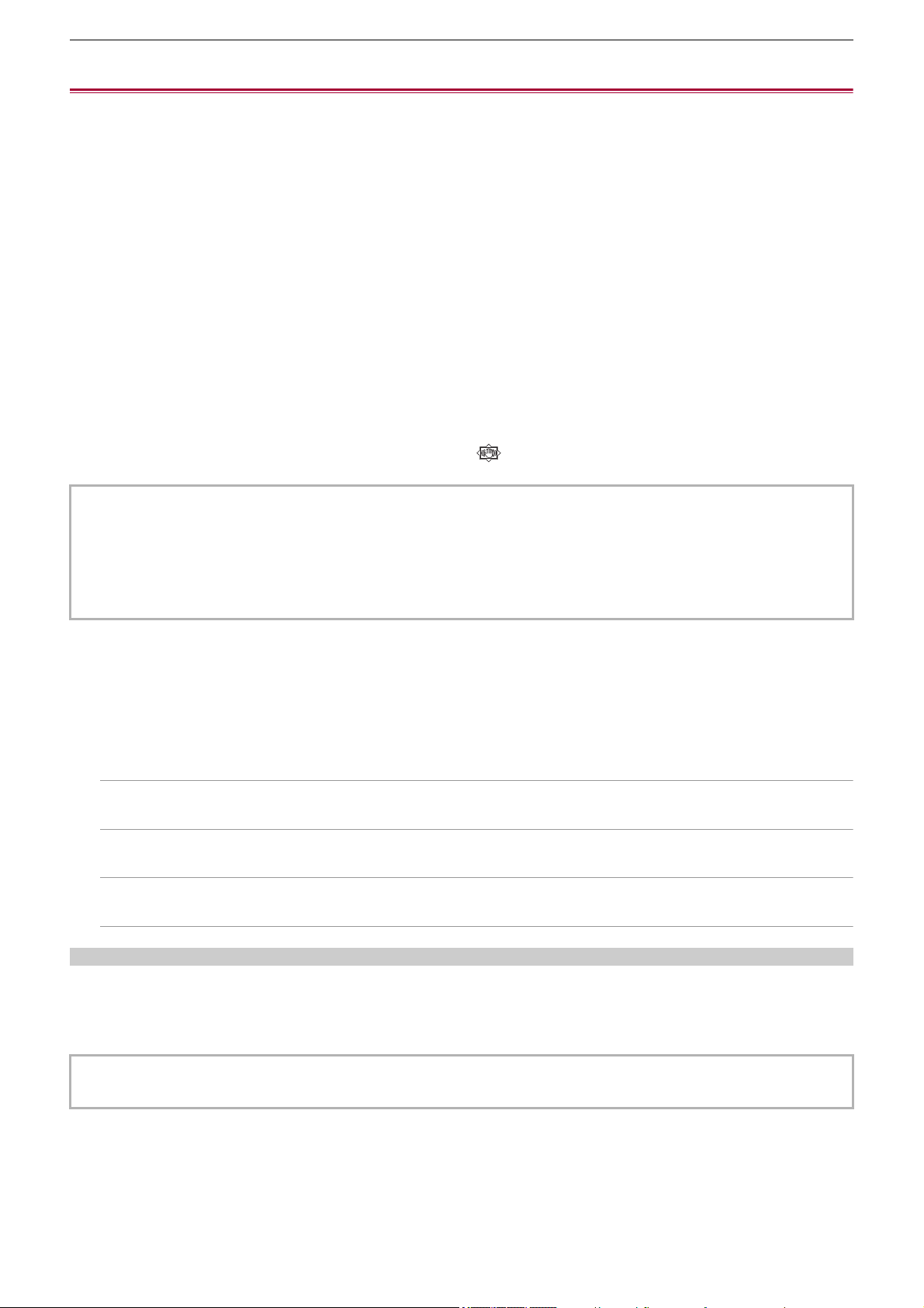
Convenient shooting functions – Optical image stabilizer function
213
Optical image stabilizer function
Camera shake can be reduced by using the optical image stabilizer function when shooting while holding the main unit by hand.
You can use the hybrid optical image stabilizer function.
The hybrid optical image stabilizer function is an optical image stabilizer that combines optical and electronic methods.
Switching enable/disable of the optical image stabilizer function
1
Select the [CAMERA] menu ¨ [SW MODE] ¨ [O.I.S.] ¨ [ON].
You can also either press the USER button assigned to [O.I.S.] or touch the USER button icon to enable/disable the optical
image stabilizer function. (ÎAssigning functions to the USER buttons: 65)
[O.I.S.] is set in the <O.I.S.>/<USER6> button at the time of purchase.
Switching enable/disable of the hybrid optical image stabilizer function
1
Select the [CAMERA] menu ¨ [SW MODE] ¨ [O.I.S.] ¨ [ON].
2
Select the [CAMERA] menu ¨ [SW MODE] ¨ [HYBRID O.I.S.] ¨ [ON].
Enable the hybrid optical image stabilizer function for more powerful image stabilization when holding the main unit and
shooting a subject far away with zoom.
When the hybrid optical image stabilizer function is enabled, is displayed on the LCD monitor.
Optical image stabilizer settings according to shooting conditions
You can set the optical image stabilizer settings according to the shooting conditions.
1
Select the [CAMERA] menu ¨ [SW MODE] ¨ [O.I.S.] ¨ [ON].
2
Select the [CAMERA] menu ¨ [SW MODE] ¨ [O.I.S. MODE] ¨ [NORMAL]/[PAN/TILT]/
[STABLE].
[NORMAL]:
Specifies the standard setting for a good balance of correction for large and small camera shake.
[PAN/TILT]:
Specifies a setting appropriate for shooting that uses a lot of panning and tilting of the camera.
[STABLE]:
Specifies a setting appropriate for fixing a composition to shoot a subject.
Utilizing the USER button
Each press of the USER button assigned [O.I.S. MODE] or each touch of the USER button icon switches the mode in the order
[NORMAL], [PAN/TILT], [STABLE].
• For USER button settings (
ÎAssigning functions to the USER buttons: 65)
• In the following cases, [HYBRID O.I.S.] is fixed to [OFF]:
– When the [CAMERA] menu
¨ [SW MODE] ¨ [O.I.S.] ¨ [OFF] is set.
– When the [SCENE FILE] menu
¨ [VFR] ¨ [ON] is set.
– When the [SYSTEM] menu
¨ [SUPER SLOW] ¨ [ON] is set.
• Stabilization may not be possible where camera shake is large.
• When recording with a tripod, it is recommended to turn [O.I.S.] [OFF].
• Stabilization may not be possible when the unit has a large amount of shake.
• When using a tripod, disabling the optical image stabilizer function will allow you to obtain natural images.

Convenient shooting functions – Dynamic range stretcher function
214
Dynamic range stretcher function
By compressing the video signal levels of the high luminosity areas that are blown out in normal shooting while maintaining the
contrast, the dynamic range can be expanded.
Switching enable/disable of the dynamic range stretcher function
1
Select the [SCENE FILE] menu ¨ [DRS] ¨ [ON].
• You can also either press the USER button assigned to [DRS] or touch the USER button icon to switch enable/disable of
the dynamic range stretcher function.
Setting the dynamic range stretcher effect
1
Select the compression level with the [SCENE FILE] menu ¨ [DRS EFFECT DEPTH].
• In the following case, [DRS] cannot be set:
– When the [SCENE FILE] menu
¨ [VFR] ¨ [ON] is set.
– When the [SYSTEM] menu
¨ [SUPER SLOW] ¨ [ON] is set.
– (For the )
When the [SCENE FILE] menu
¨ [GAMMA MODE SEL] ¨ [HLG]/[V-Log] is set.
• If there are extremely dark or bright parts or the brightness is insufficient, the effect may not be clear.

Convenient shooting functions – Time stamp function
215
Time stamp function
You can record the date and time of shooting on the images.
1
Select the information to record in the [RECORDING] menu ¨ [TIME STAMP].
[OFF]:
Does not superimpose the date and time.
[DATE]:
Superimposes only the date.
[TIME]:
Superimposes only the time.
[DATE&TIME]:
Superimposes the date and time.
The date and time of recording is displayed in the bottom-center of the LCD monitor.
• The order to display the year, month, and day of the time stamp follows the settings in the [OTHERS] menu ¨ [CLOCK] ¨
[DATE FORMAT].
• The display of the month for the time stamp to record on the image is in English.
• The size of the characters and the display position of the time stamp varies depending on the recording format.
• The time stamp is not recorded in the following cases.
– When the [SCENE FILE] menu
¨ [VFR] ¨ [ON] is set.
– (For the )
When the [SCENE FILE] menu
¨ [GAMMA MODE SEL] ¨ [V-Log] is set.
– When the [SYSTEM] menu
¨ [SUPER SLOW] ¨ [ON] is set.
– When the [NETWORK] menu ¨ [NETWORK FUNC] ¨ [STREAMING] is set.
• The position to display the time stamp can not be changed.
• The time stamp is displayed even in the screen of the LCD monitor, the image of the viewfinder, and the image output from
the <SDI OUT>
*
/<HDMI> terminals.
For the following recording formats, the time stamp displayed on the LCD monitor/viewfinder images will have a different
character size and display position to the time stamp recorded.
– Recording formats with 1280×720 resolution
* Available for use when using .
• The external output is delayed by one frame when superimposing the time stamp.
• The [VIDEO OUT/LCD/VF] menu
¨ [INDICATOR] ¨ [DATE/TIME] setting is disabled when superimposing the time stamp.
• The time stamp is an image signal recorded superimposed to the subject. Therefore, the peaking display of the focus assist
function and zebra pattern detection are enabled also to the time stamp display. The time stamp is also displayed
horizontally inverted when set to the [VIDEO OUT/LCD/VF] menu
¨ [LCD] ¨ [SELF SHOOT] ¨ [MIRROR].

Convenient shooting functions – Waveform monitor function
216
Waveform monitor function
Waveform of the image can be displayed.
1
Press the USER button assigned to [WFM] or touch the USER button icon.
(
ÎAssigning functions to the USER buttons: 65)
It is set in the <WFM>/<USER4> button icon at the time of purchase.
Press the USER button or touch the USER button icon again to return to the normal display.
• The display switches each time the USER button is pressed or the USER button icon is touched when the [VIDEO OUT/
LCD/VF] menu
¨ [EI ASSIST] ¨ [WFM MODE] ¨ [WAVE/VECTOR] is set.
Setting the displaying of the waveform monitor
Displaying of the waveform and the vector can be switched.
1
Select the display of the waveform monitor in the [VIDEO OUT/LCD/VF] menu ¨ [EI
ASSIST]
¨ [WFM MODE].
[WAVE]:
Displays the waveform.
[VECTOR]:
Displays the vector.
[WAVE/VECTOR]:
Displays the waveform and the vector. Each time you either press the USER button assigned to [WFM] or touch the USER
button icon, the display switches in the order waveform, vector, no display.
Setting the transmittance
The transmittance of the waveform monitor can be set.
1
Select the transmittance in the [VIDEO OUT/LCD/VF] menu ¨ [EI ASSIST] ¨ [WFM
TRANSPARENCE].
• The transmittance can be selected from [0%], [25%], or [50%].
• The waveform monitor cannot be recorded.
• The waveform monitor is not displayed when using enlarged display function in the focus assist function.
• The waveform monitor is automatically displayed when setting some of the menu to perform the image quality adjustment.
Convenient shooting functions – Digital zoom function
217
Digital zoom function
1
Press the USER button to which [D.ZOOM] is assigned or touch the USER button
icon. (
ÎAssigning functions to the USER buttons: 65)
It is set in the <D.ZOOM>/<USER7> button icon at the time of purchase.
Each time you either press the USER button or touch the USER button icon, the enlargement rate switches in the order 2×,
5×, 10×, disabled.
• The image quality decreases the higher the enlargement ratio when using the digital zoom.
• In the following cases, digital zoom cannot be used:
– When using the area mode function
– When using the face detection/tracking AE&AF function
• The digital zoom is canceled when the power is turned off.

Convenient shooting functions – Level gauge
218
Level gauge
A level gauge that indicates the horizontal and vertical inclinations of the unit can be displayed on the LCD monitor.
The line of the level gauge is displayed in orange while the unit is inclined. The line of the level gauge will change from orange
to light blue, and then to white when the inclination of the unit is corrected. It will indicate up to approximately 30° in horizontal
direction, and 30° in vertical direction.
1
Select the [VIDEO OUT/LCD/VF] menu ¨ [LEVEL GAUGE] ¨ [LEVEL GAUGE] ¨ [ON].
• The display of level gauge cannot be recorded.
• The level gauge is not displayed when the enlarged display function of the focus assist function is enabled.
• If [SELF SHOOT] is set to [MIRROR], the electronic level will not be displayed when you record yourself. (
Î[SELF
SHOOT]: 101
)
• Even when the level gauge line is white, there still may be a incline of approximately 1
o
.
• The level gauge may not display correctly while moving the unit.
• The level gauge may not display correctly when shooting with the unit inclined excessively upward or downward.
• You can either press the USER button assigned to [LEVEL GAUGE] or touch the USER button icon to switch display/hide of
the level gauge.
• You can either press the USER button assigned to [LEVEL GAUGE SET] or touch the USER button icon to set the current
horizontal and vertical directions as the reference value of the level gauge. Restore the set value in the [VIDEO OUT/LCD/
VF] menu
¨ [LEVEL GAUGE] ¨ [LEVEL GAUGE RESET].
• For USER button settings (
ÎAssigning functions to the USER buttons: 65)

Convenient shooting functions – Flash band compensation (FBC) function
219
Flash band compensation (FBC) function
This compensates for the phenomena of light and dark bands (flash bands) that horizontally divide images recorded in
environments where there are flashes from other cameras, and reduces their effect.
(A) Recorded image
(B) Flash emitted
(C) Flash bands
(D) Time
Flash band compensation function settings
You allocate the flash band compensation function to a USER button to use it. (
ÎAssigning functions to the USER buttons: 65)
[FBC] is displayed on the camera image screen when the flash band compensation function is enabled.
When using the flash band compensation function
The flash band compensation function works whenever the brightness in the lower part of the screen changes greatly,
irrespective of the presence of flashes. For example, the flash band compensation function may operate under some recording
environments, such as when zooming in or out on a bright window. It is recommended to use the function in recording
environments where flashes are anticipated.
Note that due to the recording environment, even when there are flashes, you may not get sufficient results from the flash band
compensation function.
• The following phenomena may occur when there are flashes. These are due to the flash band compensation function, and
do not indicate a malfunction.
– Moving subjects appear to stop momentarily.
– Resolution drops when there are flashes.
– Horizontal lines are visible when there are flashes.
• In the following cases, this cannot be set.
– In auto mode
– When the frame rate of the [REC FORMAT] is 29.97p, 23.98p, or 25.00p.
– When the [SCENE FILE] menu
¨ [VFR] ¨ [ON] is set.
– When the [SYSTEM] menu
¨ [SUPER SLOW] ¨ [ON] is set.
• The shutter speed is set to 1/60 or 1/50. The shutter speed cannot be adjusted.
(A)
(C)
(B)
(D)

Convenient shooting functions – Operation icon screen display
220
Operation icon screen display
You can select the scene file or execute the functions assigned to [USER10] through [USER14].
Displaying the operation icon screen
1
Either touch and hold the screen for approximately 2 seconds in the camera
recording screen, or press the multidial when [ ICONS] is displayed.
• The operation icon screen is displayed.
The unit returns to the camera image screen from the operation icon screen in the following cases.
– When the <EXIT> button is pressed
– When anything other than the icons is touched
– When the touch operation of the LCD monitor is not performed for approximately 5 seconds
1 Scene file (1 to 6) icon
Either press the multidial with the cursor in position or touch the icon to select each of the scene files.
The name of each scene file is displayed on the second line of the icon.
2 [USER10] to [USER14] icon
Either press the multidial with the cursor in position or touch the icon to execute the functions assigned to each of
[USER10] to [USER14].
Each function assigned to [USER10] through [USER14] is displayed in the icon.
F1:
************************************************
F2: F3: F4: F5: F6:
USER10
USER11
USER12
USER13
USER14
1
2
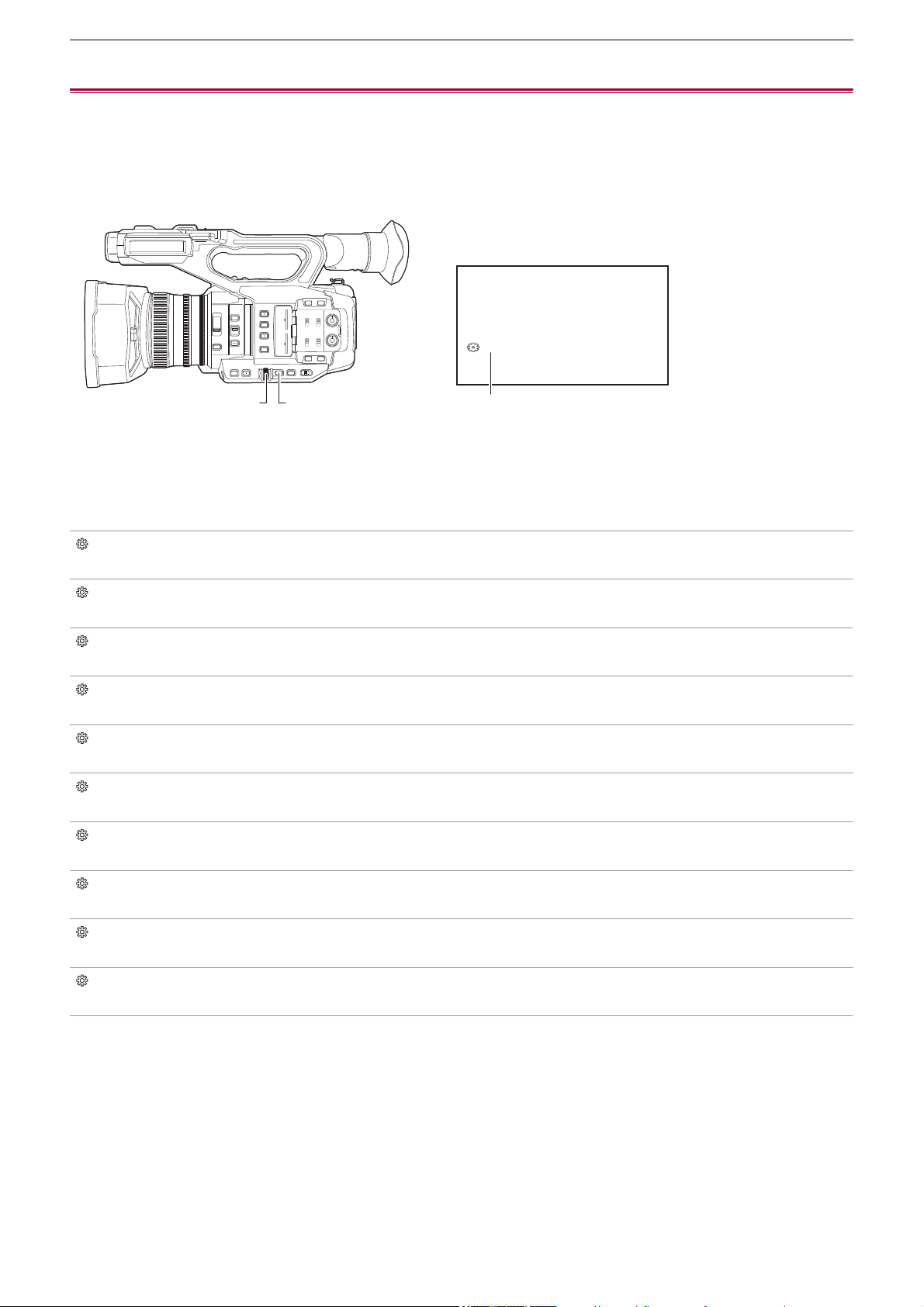
Convenient shooting functions – Multi manual function
221
Multi manual function
Operate the multidial to change settings and perform other operations without displaying the menu.
You can also switch between the functions and adjust their settings.
≥Displaying the operation icon screen: 222
≥Adjusting headphone volume: 222
(A) Multidial
(B) <EXIT> button
(C) Multi manual function
You can execute the following functions.
[ ICONS]:
Displays the operation icon screen.
[ GAIN]:
Sets the gain value. (
ÎGain: 152)
[SHUTTER]:
Sets the shutter speed. (
ÎSetting the shutter speed: 159)
[ SYNCHRO]:
Sets the synchro scan shutter speed. (
ÎSynchro scan shutter speed: 160)
[WB]:
Sets the variable value for the white balance. (
ÎSetting the variable value for the white balance: 165)
[ AE LEVEL]:
Sets the exposure compensation value (ÎAE level (exposure compensation): 154)
[ FRAME RATE]:
Sets the frame rate of the variable frame rate recording. (
ÎVariable frame rate (VFR): 189)
[ AREA]:
Adjusts the area size of the area mode function. (ÎArea mode function: 161)
[ AF AREA]:
Sets the AF area width adjustment function. (
ÎAF area width adjustment: 157)
[ AUDIO MON]:
Adjusts the headphone volume.
(C)
ICONS
(A) (B)
Convenient shooting functions – Multi manual function
222
To change the function you adjust
1
Make the settings to enable selection of the multi manual function.
Set items other than [ ICONS] and [ AUDIO MON] as follows.
[GAIN]
Set to manual gain mode (
ÎGain: 152)
[ SHUTTER]
Set to manual shutter mode (
ÎSetting the shutter speed: 159)
[ SYNCHRO]
Set to manual shutter mode and set [SYNC SCAN] to [ON]. (
ÎSynchro scan shutter speed: 160)
[WB]
Press the <WHITE BAL> button and the USER button assigned to [AWB] to switch white balance to “VAR”
(
ÎSetting the variable value for the white balance: 165)
[ AE LEVEL]
Set one of iris, gain, or shutter to auto and set [AE LEVEL] to [ON]. (
ÎAE level (exposure compensation): 154)
[ FRAME RATE]
Set to a [FILE FORMAT]/[REC FORMAT] that supports variable frame rate recording, then set [VFR] to [ON].
(
ÎVariable frame rate (VFR): 189)
[ AREA]
Press the USER button assigned to [AREA] to turn the area function on (
ÎArea mode function: 161)
[ AF AREA]
Switch to auto focus mode and set [AF AREA WIDTH] to [ON]. (
ÎAF area width adjustment: 157)
• If [ ICONS] is selected, turn the multidial to select the operation icon.
2
Turn the multidial to select the function you want to set, then press the multidial to
confirm.
The screen display for the selected function is highlighted in orange.
3
Press the multidial to end the settings.
Displaying the operation icon screen
1
Turn the multidial to display the [ ICONS].
2
Press the multidial.
The operation icon screen is displayed.
Adjusting headphone volume
Adjust the headphone volume during recording.
1
Connect the headphones to the headphone terminal.
2
Turn the multidial to display [ AUDIO MON].
3
Press the multidial.
4
Turn the multidial to adjust the volume.
There is no change to the sound that is actually recorded.
5
Press the multidial.
The setting changes to the value displayed and exits.
Press the <EXIT> button to exit without changing the setting.
• If no operations are performed in Step 4, the setting is ended.

223
Playback
Data including additional information such as image, audio, and meta data that are recorded by single shooting is saved as a
clip. Playback, copy, etc., of the clip can be performed on the unit.
≥Thumbnail operation: 224
≥Playing back clips: 229
≥Useful playback function: 232
≥Copying clip: 233
≥Deleting clips: 234
≥Protecting clips: 235
≥Restoring clips: 236
≥Still image recording function: 237

Playback – Thumbnail operation
224
Thumbnail operation
≥Thumbnail operation overview: 224
≥Thumbnail screen: 225
Thumbnail operation overview
A clip is a group of data recorded by a single shooting, which includes additional information such as image, audio, and meta
data.
The following operations can be performed while viewing the clip thumbnails displayed on the LCD monitor.
• Playback
• Delete
• Protect
• Copy (only the clips recorded in AVCHD)
You can do these operations either with the multidial or by touching the LCD monitor.
• You can switch the memory card to be played back by pressing the USER button assigned to [SLOT SEL]. (
ÎAssigning
functions to the USER buttons: 65
)
Playback – Thumbnail operation
225
Thumbnail screen
Press the <THUMBNAIL> button to display the thumbnail screen while displaying the camera image screen.
Press the <THUMBNAIL> button again to display the camera image screen.
The clips in the recording file format (MOV/MP4/AVCHD) selected in the [SYSTEM] menu
¨ [FILE FORMAT] are displayed in
the thumbnail screen.
• When you press the <MENU> button while displaying the thumbnail screen, you can perform thumbnail screen menu
operations.
* Displayed when using .
1 Clip status display
[ALL SLOT]:
Displays all the clips recorded on every memory card in each card slot. Displays in [ALL SLOT] when the thumbnail screen
is displayed from the camera image screen.
[SLOT1]:
Displays only the clips recorded on the memory card in card slot 1.
[SLOT2]:
Displays only the clips recorded on the memory card in card slot 2.
[SLOT1→SLOT2]:
Displayed when copying from the memory card in card slot 1 to the memory card in card slot 2.
[SLOT2→SLOT1]:
Displayed when copying from the memory card in card slot 2 to the memory card in card slot 1.
[SAME FORMAT]:
Displays only the clips recorded in the same format as the system format.
• Clips recorded in the same format match the current settings for each item of the [SYSTEM] menu
¨ [FREQUENCY]/
[FILE FORMAT]/[REC FORMAT].
2 Function display
This is displayed during the operation of copy, delete, protect, etc.
3 File format
:
Displayed when MOV is selected as the recording file format.
:
Displayed when MP4 is selected as the recording file format.
:
Displayed when AVCHD is selected as the recording file format.
フビパヒブパ
フビパヒブパ
ヶラュ ブペハペフ
ヶラュ ブペハペフ
ラユヷヤビパパ
ラユヷヤビパパ
ヶラュ ブペハペフ
ヶラュ ブペハペフ
フビパヒパパ
フビパヒパパ
ヶラュ ビペハペヘ
ヶラュ ビペハペヘ
ラユヷヤヒブパ
ラユヷヤヒブパ
ヶラュ ビペハペヘ
ヶラュ ビペハペヘ
フビビヒブパ
フビビヒブパ
ヶラュ ビペハペヘ
ヶラュ ビペハペヘ
フビパヒパパ
フビパヒパパ
ヶラュ ビピハペベ
ヶラュ ビピハペベ
ラユヷヤヒブパ
ラユヷヤヒブパ
ヶラュ ビピハペベ
ヶラュ ビピハペベ
フビビヒブパ
フビビヒブパ
ヶラュ ビピハペベ
ヶラュ ビピハペベ
0001
0001
00:00:00.00
00:00:00.00
0002
0002
00:00:16.00
00:00:16.00
0003
0003
00:00:32.15
00:00:32.15
0004
0004
00:01:00.17
00:01:00.17
0005
0005
00:01:24.02
00:01:24.02
0006
0006
00:01:46.02
00:01:46.02
0007
0007
00:02:30.20
00:02:30.20
0008
0008
00:02:53.08
00:02:53.08
0009
00:03:30.20
000000
00
00
000
00
000
0
000
00
000
00
0
000
00
0
00
000
00
0
00
0
00
0
0
0
0
9
9
9
9
9
9
9
9
9
9
9
9
9
9
9
9
9
9
9
9
9
9
9
9
000
000
000
000
000000
0
000
0
00
000
0
000
000
000
000
000
0
000
000
000
0
00
0
000
00
0
0
9
9
9
9
9
9
9
9
9
9
9
9
9
9
9
9
9
000
000
000
000
000
000
000
000
000
000
000
000
000
000
000
000
000
000
0
000
000
000
000
000
000
000
000
000
000
000
000
00
0
0
0
00
0
0
0
9
9
9
9
9
9
9
9
9
9
9
9
9
9
9
9
9
9
9
9
9
9
9
9
9
9
9
9
9
9
9
9
9
9
9
00:
00:
0
0
00
0
00
0
0
00:
0:
0:
0
00
0
00:
0
00:
00
00:
00:
00:
0
00
00
00:
00:
00:
0
0
00:
00
:
00:
00
0
0
0
0
:
00
00:
00
00:
0
0
0
0
0
0
0
0
0
03:
03:
03
0
0
03:
3
3
3:
0
0
03
03
03
03
03
0
03
0
03
0
03
0
03
03
03
03
03
03
03
3
3
03
3
0
3
3
03
0
0
3
0
0
3
3
3
3
3
0
03
03
3
3:
3:
03:
3
03
3
0
3
0
0
30.
30.
30
3
0
30
30.
30
0
30
30.
30.
3
30
30
30
30
30
30.
30.
30
30
0.
30.
30.
30.
30.
0
30
0
0
0
30.
30.
30.
30
30.
30
0
0
30
30
30
3
30.
0
0
0
0
30
3
3
30.
30
30.
0.
30
3
3
30
0.
30.
30
3
30
0.
30
3
0
30
3
30
30
30
3
0
30
0
0
20
2
20
2
0
20
20
2
0
20
20
2
20
2
2
2
20
20
20
20
2
20
20
20
20
20
20
20
20
0
20
2
2
0
20
20
20
2
20
20
20
2
2
20
2
2
2
0
2
2
0
20
2
2
2
2
0
0
2
0
0
20
2
0
20
0
2
2
2
2
2
2
2
2
0
0
0
00:
00:
0
00
00
0
0
00
0
0
0
00
0
00
0
00:
00:
00
0
00
00
0
00:
00
0
00:
00
00
00
00
0
00
00
0
00
00:
00:
00
00
0:
0
00:
0
00:
00
00:
00:
0
00
0
0
0
00
0
00
0
00
0
00
00:
:
00
00
0
00:
0
0
0
0
0
0
0
0
0
0
00
0
0
0
0
0
0
0
0
0
00
0
0
:
03:
03:
03
03
03
0
03
03:
3
03
3
03
0
03
03
03
03
03:
03
03
3
03
03
0
03
0
03
0
03
03
03
03
03
3
03
03
0
0
3
03
0
0
3
3:
03
0
0
0
0
03
0
3
03
0
0
03
:
0
0
03
0
03:
3
3
03:
0
0
03
0
03
0
0
3
03
3
0
03
0
03
03
3
0
3
30.
30
3
3
30
3
30
30.
0
30
30.
0
30
30
3
30
30
30
30
30
30
30.
30
30.
.
0
30.
30.
30.
3
0
0
30
0
3
3
30
0
3
3
30.
0
30
0
3
3
30.
3
30
0
3
30
0.
30
3
3
0
3
3
30
0.
30
0
30
3
0
0
30
0
20
2
2
20
20
20
2
0
20
20
2
20
2
2
20
20
20
20
20
2
20
20
20
20
20
20
20
20
20
20
2
2
2
0
0
20
20
2
20
2
0
20
20
0
2
0
2
2
2
2
2
2
2
20
2
2
2
2
0
2
0
2
2
20
2
2
2
2
2
0
0
2
2
2
2
2
0
2
2
0
20
2
0
1
10
2 3 4 5 6
9
78
Playback – Thumbnail operation
226
:
Displayed when MP4, or AVCHD is selected as the recording file format and when even one MOV clip is on any of the
memory cards.
:
Displayed when MOV, or AVCHD is selected as the recording file format and when even one MP4 clip is on any of the
memory cards.
:
Displayed when MOV, or MP4 is selected as the recording file format and when even one AVCHD clip is on any of the
memory cards.
4 Media status display
The card slot number of the memory card where the clip in the cursor position is recorded is displayed in yellow.
5 Displaying the connection status of the wired LAN, wireless LAN or USB tethering
Displays the connection status of the wired LAN, wireless LAN or USB tethering.
(No display):
It is not connected to the wired LAN, wireless LAN or USB tethering. It is set to the [NETWORK] menu
¨ [DEVICE SEL] ¨
[OFF].
:
A status where the wired LAN is set and ROP is not connected.
:
A status where the wired LAN is set, but the wired LAN is not working correctly.
:
A status where the wireless LAN is set and ROP is not connected.
:
A status where the wireless LAN is set, but the wireless LAN is not working correctly.
*
:
A status where the USB tethering set and ROP is not connected.
*
:
A status where USB tethering is set, but USB tethering is not working correctly.
6 Power status display
:
Displays the remaining battery level while powered with the battery.
:
Displayed when powered with the AC adaptor.
7 Cursor
8 Clip that cannot be played back
Displays when the clip cannot be played back in the unit such as standard violation.
9 Page switching button
Switches the page of the thumbnail screen.
[#]:
Moves to previous page
[$]:
Moves to next page
10 Scroll bar
Indicates which part of the whole thumbnail is currently being viewed.

Playback – Thumbnail operation
227
Display of the clips in the thumbnail screen
* Displayed when using .
1 Thumbnail number
Displays the thumbnail number in [0001] to [9999].
Normally, the number assigned to the clip in the order of recording is displayed.
2 Resume play status
3 Number of recording pixels, system frequency
4 Recording file format, recording codec
5 Protection status of the clip
This is displayed when the clip is protected.
6 Standard time code/clip name
The first 8 digits for the time code when starting shooting of a clip or the file name of the clip are displayed in alphanumeric.
The information to display is set in the [THUMBNAIL] menu
¨ [DISPLAY] ¨ [DATA].
7 Delete selection status
8 Clip that cannot be played back
This is displayed when the clip cannot be played back with the unit because the system frequency is different, etc.
9 Copy selection status
This is displayed when the clip is selected.
10 Dual codec recording
*
Displayed on clips (main recording/sub recording) that used dual codec recording.
Display of clip information
Displays the information of the clip where the cursor is positioned.
1
Move the yellow cursor to the clip to display the clip information.
2
Select the [THUMBNAIL] menu ¨ [CLIP] ¨ [INFORMATION].
The clip information is displayed.
フビパヒブパ
フビパヒブパ
ヶラュブペハペフ
ヶラュブペハペフ
0001
0001
00:00:00.00
00:00:00.00
フビパヒパパ
フビパヒパパ
ヶラュビペハペヘ
ヶラュビペハペヘ
0001
0001
00:00:00.00
00:00:00.00
10
フビパヒブパ
フビパヒブパ
ヶラュブペハペフ
ヶラュブペハペフ
0001
0001
00:00:00.00
00:00:00.00
モヷヤラュ ヱラ
モヷヤラュ ヱラ
ョラュブペハペフ
ョラュブペハペフ
0001
0001
00:00:00.00
00:00:00.00
2
7
1
8
93
4
6
5
Playback – Thumbnail operation
228
Clip information
* Displayed when using .
1 Clip that cannot be played back
This is displayed when the clip cannot be played back with the unit because the system frequency is different, etc.
2 Thumbnail number
3 Protect status of the clip
:
This is displayed when the clip is protected.
D
*
:
Displayed on clips (main recording/sub recording) that used dual codec recording.
4 Thumbnail image
5 Clip name
6 [START TC]
Displays the time code value at the start of the recording.
7 [START UB]
Displays the user bits value at the start of the recording.
8 [DATE]
Displays the date of the recording.
9 [TIME]
Displays the time at the start of recording.
10 [DURATION]
Displays the time length of the clip.
11 [PIXEL/FREQ]
Displays the recording format of the clip.
12 [CODEC]
Displays the recording file format and the recording codec of the clip.
13 [FRAME RATE]
Displays the recording frame rate of the clip.
• Displays when the variable frame rate recording function is enabled and the clip is recorded in a frame rate different from
the system frequency.
• Displays the frame rate for super slow recording.
14 [GAMMA]
Displays the gamma of the clip.
• Displayed when the [SYSTEM] menu
¨ [FILE FORMAT] is set to other than [AVCHD].
123
6
45
7
8
9
10
11
12
13
14
'
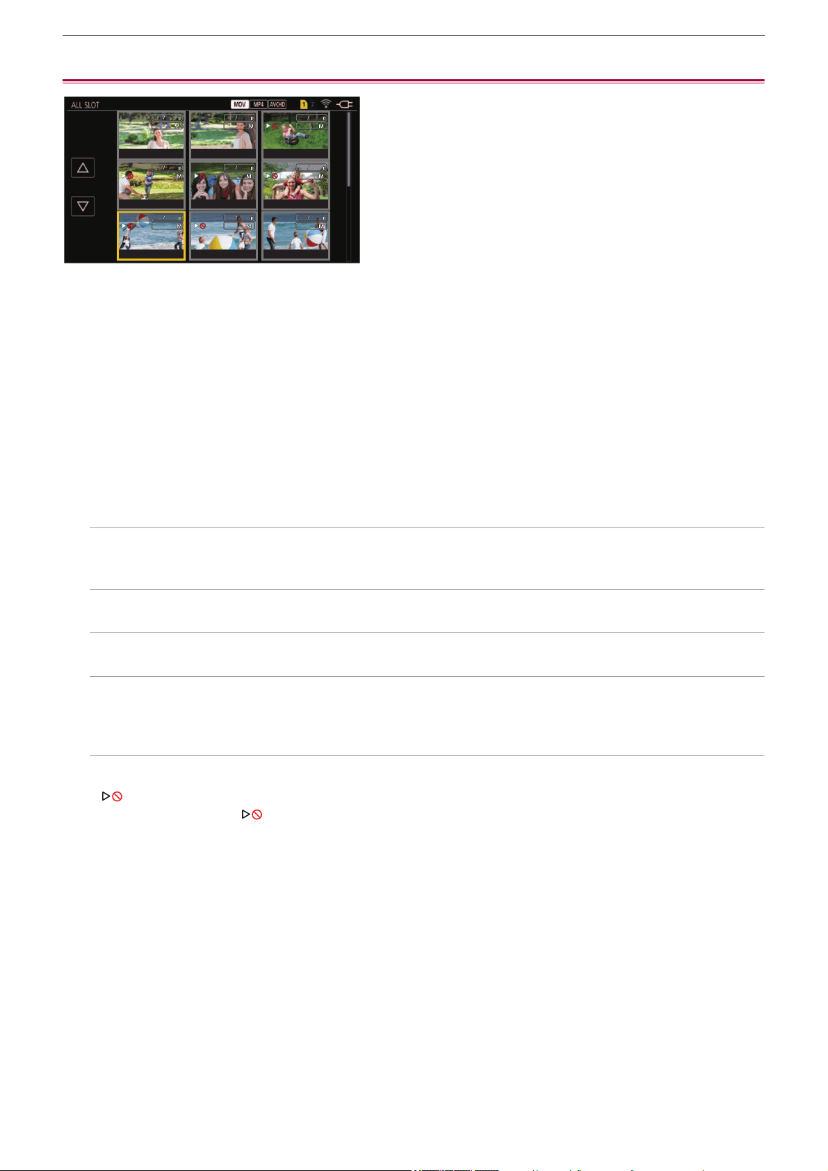
Playback – Playing back clips
229
Playing back clips
1
In the [SYSTEM] menu ¨ [FREQUENCY], select the system frequency to play back.
2
In the [SYSTEM] menu ¨ [FILE FORMAT], select the file format to play back.
3
In the [SYSTEM] menu ¨ [REC FORMAT], select the signal format and codec mode to
play back.
4
Press the <THUMBNAIL> button.
The thumbnail screen is displayed.
5
Press the <MENU> button while the thumbnail screen is displayed.
The menu is displayed.
6
In the [THUMBNAIL] menu ¨ [PLAYBACK] ¨ [CLIP SEL], select the card slot of the
memory card to play back.
[ALL SLOT]:
Displays all the clips recorded on every memory card in each card slot.
Displays in the order of the clips in card slot 1, and then clips in the card slot 2.
[SLOT1]:
Displays only the clips recorded on the memory card in card slot 1.
[SLOT2]:
Displays only the clips recorded on the memory card in card slot 2.
[SAME FORMAT]:
Displays only the clips recorded in the same format as the system format.
• Clips recorded in the same format match the current settings for each item of the [SYSTEM] menu
¨ [FREQUENCY]/
[FILE FORMAT]/[REC FORMAT].
7
Select the clip to play back.
• is displayed on the clip that cannot be played back.
• To play back the clip with displayed, check the information of the clip with the clip information, and try operating from
the beginning again.
フビパヒブパ
フビパヒブパ
ヶラュ ブペハペフ
ヶラュ ブペハペフ
ラユヷヤビパパ
ラユヷヤビパパ
ヶラュ ブペハペフ
ヶラュ ブペハペフ
フビパヒパパ
フビパヒパパ
ヶラュ ビペハペヘ
ヶラュ ビペハペヘ
ラユヷヤヒブパ
ラユヷヤヒブパ
ヶラュ ビペハペヘ
ヶラュ ビペハペヘ
フビビヒブパ
フビビヒブパ
ヶラュ ビペハペヘ
ヶラュ ビペハペヘ
フビパヒパパ
フビパヒパパ
ヶラュ ビピハペベ
ヶラュ ビピハペベ
ラユヷヤヒブパ
ラユヷヤヒブパ
ヶラュ ビピハペベ
ヶラュ ビピハペベ
フビビヒブパ
フビビヒブパ
ヶラュ ビピハペベ
ヶラュ ビピハペベ
フビビヒパパ
フビビヒパパ
ョラュブペハペフ
ョラュブペハペフ
0001
0001
00:00:00.00
00:00:00.00
0002
0002
00:00:16.00
00:00:16.00
0003
0003
00:00:32.15
00:00:32.15
0004
0004
00:01:00.17
00:01:00.17
0005
0005
00:01:24.02
00:01:24.02
0006
0006
00:01:46.02
00:01:46.02
0007
0007
00:02:30.20
00:02:30.20
0008
0008
00:02:53.08
00:02:53.08
0009
0009
00:03:30.20
00:03:30.20
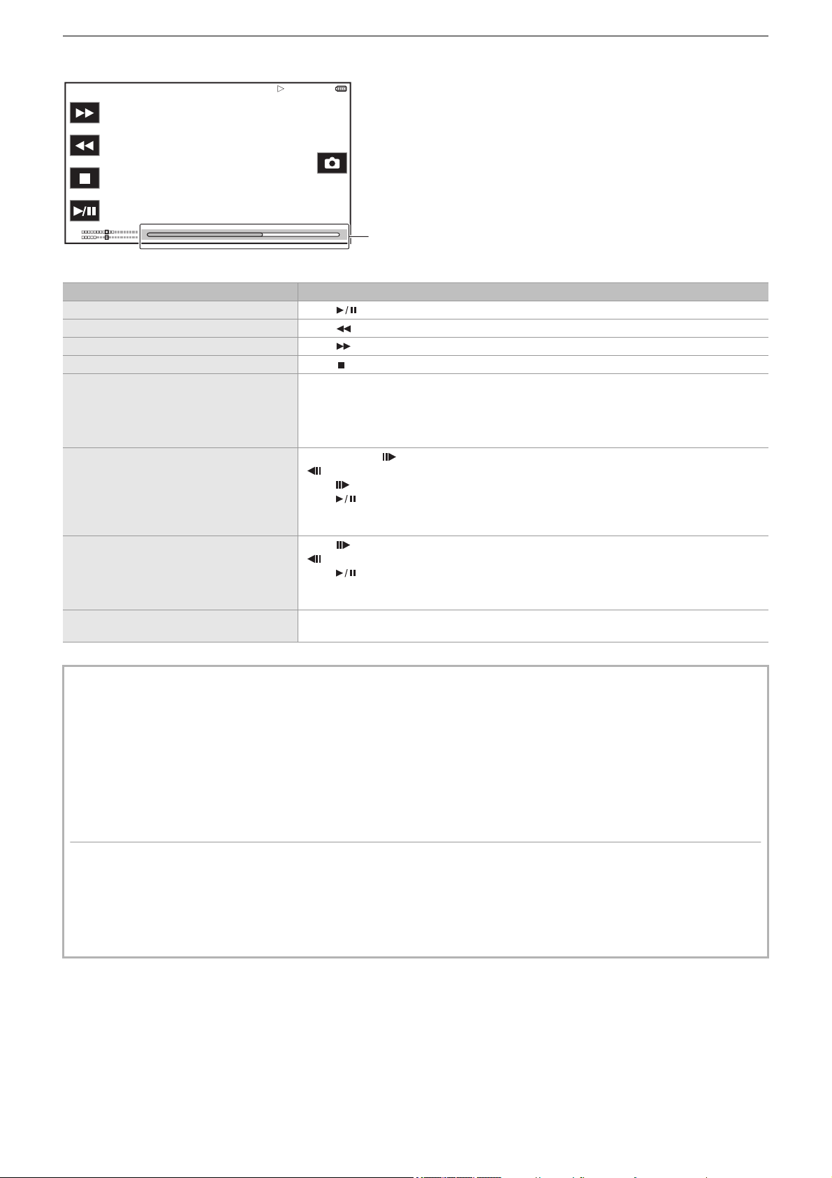
Playback – Playing back clips
230
Playback from touch operations and operation icons
(A) Direct playback bar
Playback operation Operating procedure
Playback/pause Touch .
Fast-reverse playback Touch . Touch twice to increase the speed.
Fast-forward playback Touch . Touch twice to increase the speed.
Stop (return to thumbnail screen) Touch .
Skip playback
(cue up of the clip)
Touch the LCD monitor while playing back, and slide from right to left (left to right).
When sliding from left to right, the clip skips to the beginning of the previous clip if the current
playback position of the clip is at less than 3 seconds from the beginning. The clip skips to the
beginning of the current clip if the current playback position of the clip is at 3 seconds or more
from the beginning.
Slow playback
Touch and hold while paused.
( is reverse slow playback)
When is touched, slow playback is performed with continuous frame-by-frame playback.
When is touched, playback returns to normal.
The frame-by-frame interval and the display time for each frame for the reverse slow playback
differ depending on the type of the clip.
Frame-by-frame playback
Touch while paused.
( is reverse frame-by-frame playback)
When is touched, playback returns to normal.
The frame-by-frame interval for reverse frame-by-frame playback differs depending on the
type of the clip.
Direct playback
Touch the direct playback bar, or slide it while touching.
The playback video is paused during the operation. Playback is started by releasing the finger.
• If the operation icons are displayed but not touched for a while, the operation icons disappear. To display again, touch the
screen.
• Operations of the unit or some performance may become slow for the clip with large file size.
• Operations of the unit or some performance may become slow when there are large number of clips on the memory card.
• Playback will stop once by switching the card slot when the [THUMBNAIL] menu
¨ [PLAYBACK] ¨ [CLIP SEL] ¨ [ALL
SLOT]/[SAME FORMAT] is set, and then the clips of all the memory cards are displayed. Playback is not possible across 2
memory cards.
• Playback stops when the memory card is removed during playback.
• During playback of a clip, playback may be suspended or black screen may be displayed due to switching of a clip.
Motion picture compatibility
• This unit is based on AVCHD Progressive/AVCHD.
• Even if the devices used have compatible standards, when playback of clip recorded using another device is performed
using this device, or when clip recorded using this device is played back in another device, playback may not proceed
normally, or may not be possible. (Please check compatibility in the instruction manual of your device.)
• Clips recorded with devices other than this unit are not supported by this unit.
TCR 12:59:59:23
CH1
CH2
(A)

Playback – Playing back clips
231
Adjusting the volume during playback
You can adjust the playback volume by operating the zoom lever.
Towards <T>: Raise the volume
Towards <W>: Lower the volume
• If no operations are performed, the setting is ended.
• The <EXIT> button is disabled.
T
T
W
W

Playback – Useful playback function
232
Useful playback function
Resume play
When the playback of a clip is stopped midway, it will start the playback from the position that stopped the playback when it is
played back the next time.
1
Select the [THUMBNAIL] menu ¨ [PLAYBACK] ¨ [RESUME PLAY] ¨ [ON].
When the playback of a clip is stopped midway, [ ] is displayed on the clip in the thumbnail screen.
• Resume playback is canceled in following cases. (The [RESUME PLAY] setting cannot be set to [OFF].)
– When the power is turned off
– When the thumbnail screen is canceled by pressing the <THUMBNAIL> button
– When the [THUMBNAIL] menu
¨ [PLAYBACK] ¨ [CLIP SEL] is changed
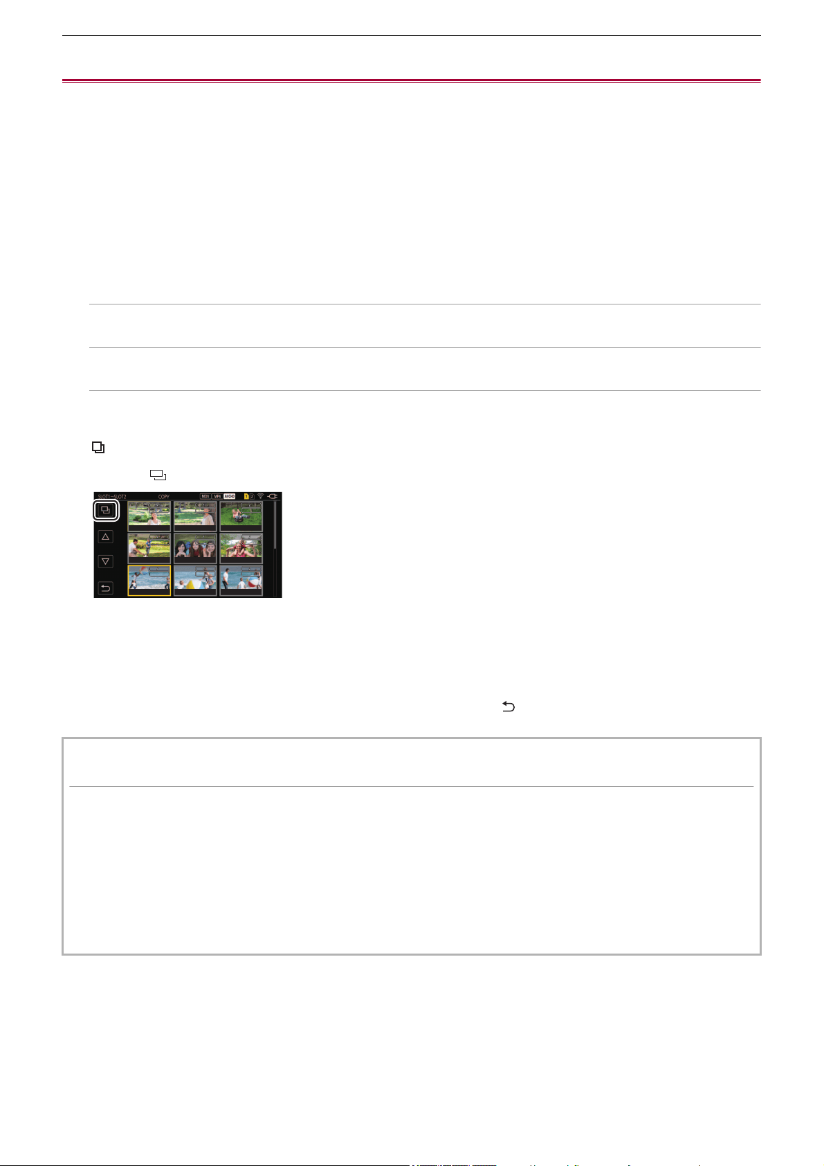
Playback – Copying clip
233
Copying clip
Clips can be copied between memory cards.
Only the clip recorded in AVCHD can be copied.
1
Press the <THUMBNAIL> button.
The thumbnail screen is displayed.
2
Press the <MENU> button while the thumbnail screen is displayed.
The menu is displayed.
3
Select the [THUMBNAIL] menu ¨ [CLIP] ¨ [COPY] ¨ [SELECT].
• Selecting [ALL] copies all the clips between the memory cards.
4
Select the card slot for the copy destination.
[SLOT1→SLOT2]:
Copies clips from the memory card in card slot 1 to the memory card in card slot 2.
[SLOT2→SLOT1]:
Copies clips from the memory card in card slot 2 to the memory card in card slot 1.
The clips on the memory card of the copy source is displayed in the thumbnail screen.
5
Select the clip to copy in the thumbnail screen.
is displayed on the selected clip.
6
Select [ ].
• This can also be selected by pressing and holding the multidial.
7
When the confirmation message is displayed, select [SET].
Progress bar is displayed, and the copy of the clip starts.
• To cancel the copy midway, select [CANCEL].
8
When the completion message is displayed, select [ ].
When deleting clips after copying is complete, before deletion make sure you play back the copied clip to confirm
that it has been copied properly.
• When there are a large number of clips, it may take longer to copy the clips.
• The clip whose recording file format is MOV/MP4 cannot be copied.
• The copy is not possible when the volume of the selected clip is larger than the available card capacity of the destination.
• The copy is not possible when the copy destination card is write protected.
• The copy is not possible when the maximum number of the clips will exceed.
• The copy is not possible when the maximum number of the playlist will exceed.
• It may not be possible to copy clips recorded on other equipment. Data that was recorded on a computer cannot be copied.
• The protection setting for clips is cleared when they are copied.
• The order of clips copied cannot be changed.
00010001
00:08:17.1500:08:17.15
00020002
00:08:47.1500:08:47.15
00030003
00:09:11.0000:09:11.00
00040004
00:09:32.1500:09:32.15
00050005
00:09:50.1500:09:50.15
00060006
00:10:08.0000:10:08.00
00070007
00:10:20.1500:10:20.15
00080008
00:10:38.1500:10:38.15
00090009
00:10:52.1500:10:52.15
モヷヤラュ ヱラモヷヤラュ ヱラ
ョラュブペハペフョラュブペハペフ
ㄊㄊ
モヷヤラュ ヱラモヷヤラュ ヱラ
ョラュブペハペフョラュブペハペフ
ㄊㄊ
モヷヤラュ ヱラモヷヤラュ ヱラ
ョラュブペハペフョラュブペハペフ
ㄊㄊ
モヷヤラュ ヱラモヷヤラュ ヱラ
ョラュブペハペフョラュブペハペフ
ㄊㄊ
モヷヤラュ ヱラモヷヤラュ ヱラ
ョラュブペハペフョラュブペハペフ
ㄊㄊ
モヷヤラュ ヱラモヷヤラュ ヱラ
ョラュブペハペフョラュブペハペフ
ㄊㄊ
モヷヤラュ ヱラモヷヤラュ ヱラ
ョラュブペハペフョラュブペハペフ
ㄊㄊ
モヷヤラュ ヱラモヷヤラュ ヱラ
ョラュブペハペフョラュブペハペフ
ㄊㄊ
モヷヤラュ ヱラモヷヤラュ ヱラ
ョラュブペハペフョラュブペハペフ
ㄊㄊ
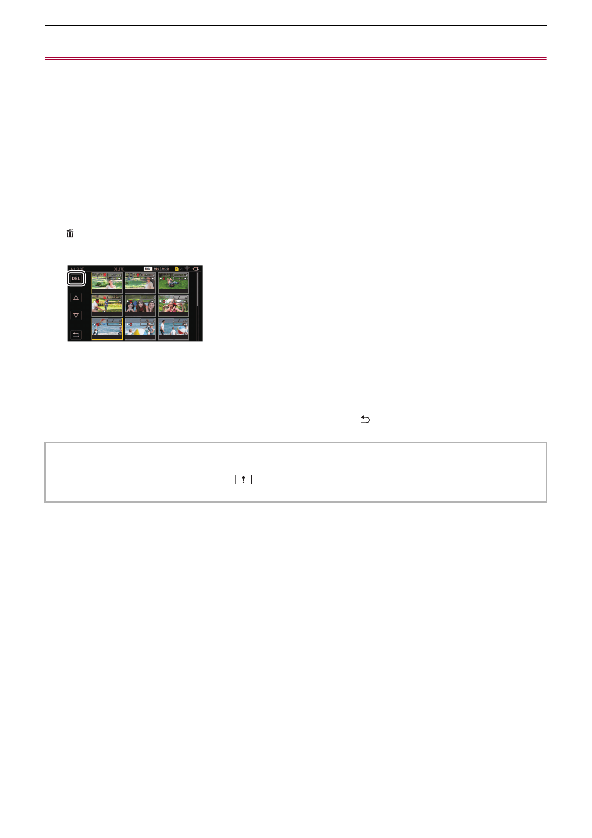
Playback – Deleting clips
234
Deleting clips
Deletes the clip.
1
Press the <THUMBNAIL> button.
The thumbnail screen is displayed.
2
Press the <MENU> button while the thumbnail screen is displayed.
The menu is displayed.
3
Select the [THUMBNAIL] menu ¨ [CLIP] ¨ [DELETE] ¨ [SELECT].
The thumbnail screen is displayed.
• When [ALL] is selected, all the clips displayed in the thumbnail screen are deleted.
The clip that is not displayed in the thumbnail screen is not deleted.
4
Select the clip to delete in the thumbnail screen.
is displayed on the selected clip.
5
Select [DEL].
• This can also be selected by pressing and holding the multidial.
6
When the confirmation message is displayed, select [SET].
Progress bar is displayed, and the deleting of the clip starts.
• To cancel midway, select [CANCEL].
7
When the completion message is displayed, select [ ].
• The protected clip cannot be deleted.
• You cannot delete clips when the card with the clip to delete is write protected.
• You cannot delete clips (thumbnail display is ) that cannot be played back.
• It may take some time if all clips were selected for deletion in Step 3.
フビパヒブパフビパヒブパ
ヶラュ ブペハペフヶラュ ブペハペフ
ラユヷヤビパパラユヷヤビパパ
ヶラュ ブペハペフヶラュ ブペハペフ
フビパヒパパフビパヒパパ
ヶラュ ビペハペヘヶラュ ビペハペヘ
ラユヷヤヒブパラユヷヤヒブパ
ヶラュ ビペハペヘヶラュ ビペハペヘ
フビビヒブパフビビヒブパ
ヶラュ ビペハペヘヶラュ ビペハペヘ
フビパヒパパフビパヒパパ
ヶラュ ビピハペベヶラュ ビピハペベ
ラユヷヤヒブパラユヷヤヒブパ
ヶラュ ビピハペベヶラュ ビピハペベ
フビビヒブパフビビヒブパ
ヶラュ ビピハペベヶラュ ビピハペベ
フビビヒパパフビビヒパパ
ョラュブペハペフョラュブペハペフ
00010001
00:00:00.0000:00:00.00
00020002
00:00:16.0000:00:16.00
00030003
00:00:32.1500:00:32.15
00040004
00:01:00.1700:01:00.17
00050005
00:01:24.0200:01:24.02
00060006
00:01:46.0200:01:46.02
00070007
00:02:30.2000:02:30.20
00080008
00:02:53.0800:02:53.08
00090009
00:03:30.2000:03:30.20

Playback – Protecting clips
235
Protecting clips
The clip can be protected.
1
Press the <THUMBNAIL> button.
The thumbnail screen is displayed.
2
Press the <MENU> button while the thumbnail screen is displayed.
The menu is displayed.
3
Select the [THUMBNAIL] menu ¨ [CLIP] ¨ [PROTECT] ¨ [SELECT].
The thumbnail screen is displayed.
4
Select the clip to protect in the thumbnail screen.
is displayed on the selected clip.
• Protect is canceled when the protected clip is selected.
• You cannot protect clips when the card with the clip to protect is write protected.

Playback – Restoring clips
236
Restoring clips
In following cases, restoration of the clip may be required depending on the condition. It may take some time to restore
depending on the error.
• When the memory card in the card slot that is flashing is removed while the card 1 access lamp or the card 2 access lamp is
flashing
• When the power is turned off by removing the battery or the AC adaptor while recording or performing record completion
process
Restoring a clip
When abnormal management information is detected, the error message [There are clips that need restoration.] is displayed on
the screen.
1
Select [SET] in the error message screen.
• Once the repair is completed, select [ ] in the confirmation message. It will return to the previous screen.
• is displayed on the clip when an abnormal management information is detected while displaying the thumbnail.
• Do not remove the memory card in the card slot that is flashing, or do not remove the battery or the AC adaptor when the
card 1 access lamp/card 2 access lamp is flashing in orange. Doing so will cause damage to the memory card.
• Use a sufficiently charged battery or AC adaptor.
• It may not be possible to completely repair depending on the condition of the data.
• To restore the clips, it is necessary that the clips are recorded for more than a certain amount of time. Especially in the
following cases, the clips may not be restored, because the number of frames to be recorded is small.
– When the variable frame rate recording function is enabled, and the frame rate lower than the system frequency is set.
– When the interval recording function is enabled.
• The clips shot before the power was turned off will not be able to play back if the repair fails.
Also, it may not be possible to record any more.
• If data recorded with other device is repaired, it may not be able to play back on the unit or other device.
• If the repair failed, turn off the unit, and turn it back on after waiting for a while. If the repair fails repeatedly, format with the
unit. All data will be erased when it is formatted, and it cannot be restored.
• Display of the thumbnail may become slower when the thumbnail information is repaired.

Playback – Still image recording function
237
Still image recording function
One frame of the recorded video can be recorded as a still image.
Number of pixels of the still image to be recorded is same as the number of pixels of the recorded video.
1
Select by touching or pressing the multidial at the scene to be recorded as a still
image while playing back.
The still image is recorded in the memory card being played back.
• It is convenient to use Pause, Slow-motion Playback and Frame-by-frame Playback.
• The playback will pause when a still image is recorded.
• Recorded still image cannot be displayed in thumbnail, played back, copied, or deleted in the unit.
• [INVALID] is displayed when the still image cannot be recorded in cases such as there is not enough remaining recording
capacity in the memory card.

238
Output format
The format to be output differs depending on the setting in the [SYSTEM] menu
¨ [FREQUENCY]/[REC FORMAT].
≥Format that can be output from the SDI OUT terminal [X2]: 239
≥Format that can be output from the HDMI terminal: 240
≥Note regarding simultaneous output to the SDI OUT terminal and the HDMI terminal [X2]: 242
Output format – Format that can be output from the SDI OUT terminal [X2]
239
Format that can be output from the SDI OUT terminal [X2]
The format that can be output from the <SDI OUT> terminal differs with following combination of the settings.
• [SYSTEM] menu
¨ [FREQUENCY]
• [SYSTEM] menu
¨ [REC FORMAT]
• [VIDEO OUT/LCD/VF] menu
¨ [VIDEO OUT SEL] ¨ [SDI OUT FORMAT]
Set to the following settings in the menus when outputting only to the <SDI OUT> terminal.
•
[VIDEO OUT/LCD/VF] menu
¨ [VIDEO OUT SEL] ¨ [SDI + HDMI OUTPUT] ¨ [OFF]
• [VIDEO OUT/LCD/VF] menu
¨ [VIDEO OUT SEL] ¨ [EXTERNAL OUT SEL] ¨ [SDI]
It is also possible to output to both the <SDI OUT> terminal and the <HDMI> terminal. (ÎNote regarding simultaneous output to
the SDI OUT terminal and the HDMI terminal [X2]: 242
)
When the [FREQUENCY] is set to [59.94Hz]
When the [FREQUENCY] is set to [50.00Hz]
* Factory setting
[REC FORMAT]
[SDI OUT FORMAT]: Output Format
Resolution Frame rate
3840×2160 59.94p [1920×1080p]: 1920×1080/59.94p 4:2:2 10 bit
[1920×1080i]
*
: 1920×1080/59.94i 4:2:2 10 bit
29.97p [1920×1080p]: 1920×1080/29.97p 4:2:2 10 bit
[1920×1080PsF]
*
: 1920×1080/29.97PsF 4:2:2 10 bit
23.98p [1920×1080p]: 1920×1080/23.98p 4:2:2 10 bit
[1920×1080PsF]
*
: 1920×1080/23.98PsF 4:2:2 10 bit
1920×1080 59.94p [1920×1080p]: 1920×1080/59.94p 4:2:2 10 bit
[1920×1080i]
*
: 1920×1080/59.94i 4:2:2 10 bit
59.94i [1920×1080i]: 1920×1080/59.94i 4:2:2 10 bit
29.97p [1920×1080p]: 1920×1080/29.97p 4:2:2 10 bit
[1920×1080PsF]
*
: 1920×1080/29.97PsF 4:2:2 10 bit
23.98p [1920×1080p]: 1920×1080/23.98p 4:2:2 10 bit
[1920×1080PsF]
*
: 1920×1080/23.98PsF 4:2:2 10 bit
1280×720 59.94p [1280×720p]: 1280×720/59.94p 4:2:2 10 bit
[REC FORMAT]
[SDI OUT FORMAT]: Output Format
Resolution Frame rate
3840×2160 50.00p [1920×1080p]: 1920×1080/50.00p 4:2:2 10 bit
[1920×1080i]
*
: 1920×1080/50.00i 4:2:2 10 bit
25.00p [1920×1080p]: 1920×1080/25.00p 4:2:2 10 bit
[1920×1080PsF]
*
: 1920×1080/25.00PsF 4:2:2 10 bit
1920×1080 50.00p [1920×1080p]: 1920×1080/50.00p 4:2:2 10 bit
[1920×1080i]
*
: 1920×1080/50.00i 4:2:2 10 bit
50.00i [1920×1080i]: 1920×1080/50.00i 4:2:2 10 bit
25.00p [1920×1080p]: 1920×1080/25.00p 4:2:2 10 bit
[1920×1080PsF]
*
: 1920×1080/25.00PsF 4:2:2 10 bit
1280×720 50.00p [1280×720p]: 1280×720/50.00p 4:2:2 10 bit
• The 3840×2160 output is not supported.
• User bits are not displayed.
• [SDI OUT FORMAT] restores the factory settings when the settings of [FREQUENCY] and [REC FORMAT] change and the
current setting values of [SDI OUT FORMAT] cannot be acquired.
• The output format when playing back from the thumbnail screen is as follows.
– It will be the value set in [SDI OUT FORMAT] when the recording resolution of the playback clip is the same as [REC
FORMAT].
– It will be factory setting of [SDI OUT FORMAT] when the recording resolution of the playback clip is different from [REC
FORMAT].
• There may be a fews seconds of images not displayed on the external device when the clips are changing over, etc.
Output format – Format that can be output from the HDMI terminal
240
Format that can be output from the HDMI terminal
The format that can be output from the <HDMI> terminal differs with following combination of the settings.
• [SYSTEM] menu
¨ [FREQUENCY]
• [SYSTEM] menu
¨ [FILE FORMAT]
• [SYSTEM] menu
¨ [REC FORMAT]
• (For the )
[VIDEO OUT/LCD/VF] menu
¨ [VIDEO OUT SEL] ¨ [HDMI OUT FORMAT]
• (For the )
[VIDEO OUT/LCD/VF] menu
¨ [HDMI OUT] ¨ [OUT FORMAT]
(For the )
Set to the following settings in the menus when outputting only to the <HDMI> terminal.
• [VIDEO OUT/LCD/VF] menu ¨ [VIDEO OUT SEL] ¨ [SDI + HDMI OUTPUT] ¨ [OFF]
• [VIDEO OUT/LCD/VF] menu
¨ [VIDEO OUT SEL] ¨ [EXTERNAL OUT SEL] ¨ [HDMI]
It is also possible to output to both the <SDI OUT> terminal and the <HDMI> terminal. (ÎNote regarding simultaneous output to
the SDI OUT terminal and the HDMI terminal [X2]: 242
)
When the [FREQUENCY] is set to [59.94Hz]
When the [FREQUENCY] is set to [50.00Hz]
*1 Factory setting
*2 Can be selected when [FILE FORMAT] is [AVCHD].
[REC FORMAT]
[HDMI OUT FORMAT]: Output Format
Resolution Frame rate
3840×2160 59.94p [3840×2160p]: 3840×2160/59.94p 4:2:2 10 bit
[3840×2160p(420/8bit)]: 3840×2160/59.94p 4:2:0 8 bit
[1920×1080p]
*1
: 1920×1080/59.94p 4:2:2 10 bit
[1920×1080i]: 1920×1080/59.94i 4:2:2 10 bit
29.97p [3840×2160p]: 3840×2160/29.97p 4:2:2 10 bit
[1920×1080p]
*1
: 1920×1080/29.97p 4:2:2 10 bit
23.98p [3840×2160p]: 3840×2160/23.98p 4:2:2 10 bit
[1920×1080p]
*1
: 1920×1080/23.98p 4:2:2 10 bit
1920×1080 59.94p [1920×1080p]
*1
: 1920×1080/59.94p 4:2:2 10 bit
[1920×1080i]: 1920×1080/59.94i 4:2:2 10 bit
[720×480p]
*2
: 720×480/59.94p 4:2:2 10 bit
59.94i [1920×1080i]
*1
: 1920×1080/59.94i 4:2:2 10 bit
[720×480p]
*2
: 720×480/59.94p 4:2:2 10 bit
29.97p [1920×1080p]: 1920×1080/29.97p 4:2:2 10 bit
23.98p [1920×1080p]
*1
: 1920×1080/23.98p 4:2:2 10 bit
[720×480p]
*2
: 720×480/59.94p 4:2:2 10 bit
1280×720 59.94p [1280×720p]
*1
: 1280×720/59.94p 4:2:2 10 bit
[720×480p]
*2
: 720×480/59.94p 4:2:2 10 bit
[REC FORMAT]
[HDMI OUT FORMAT]: Output Format
Resolution Frame rate
3840×2160 50.00p [3840×2160p]: 3840×2160/50.00p 4:2:2 10 bit
[3840×2160p(420/8bit)]: 3840×2160/50.00p 4:2:0 8 bit
[1920×1080p]
*1
: 1920×1080/50.00p 4:2:2 10 bit
[1920×1080i]: 1920×1080/50.00i 4:2:2 10 bit
25.00p [3840×2160p]: 3840×2160/25.00p 4:2:2 10 bit
[1920×1080p]
*1
: 1920×1080/25.00p 4:2:2 10 bit
1920×1080 50.00p [1920×1080p]
*1
: 1920×1080/50.00p 4:2:2 10 bit
[1920×1080i]: 1920×1080/50.00i 4:2:2 10 bit
[720×576p]
*2
: 720×576/50.00p 4:2:2 10 bit
50.00i [1920×1080i]
*1
: 1920×1080/50.00i 4:2:2 10 bit
[720×576p]
*2
: 720×576/50.00p 4:2:2 10 bit
25.00p [1920×1080p]: 1920×1080/25.00p 4:2:2 10 bit
1280×720 50.00p [1280×720p]
*1
: 1280×720/50.00p 4:2:2 10 bit
[720×576p]
*
2
: 720×576/50.00p 4:2:2 10 bit

Output format – Format that can be output from the HDMI terminal
241
• [HDMI OUT FORMAT]/[OUT FORMAT] restores the factory settings when the settings of [FREQUENCY] and [REC
FORMAT] change and the current setting values of [HDMI OUT FORMAT]/[OUT FORMAT] cannot be acquired.
• The output format when playing back from the thumbnail screen is as follows.
– It will be the value set in [HDMI OUT FORMAT]/[OUT FORMAT] when the recording resolution of the playback clip is the
same as [REC FORMAT].
– It will be factory setting of [HDMI OUT FORMAT]/[OUT FORMAT] when the recording resolution of the playback clip is
different from [REC FORMAT].
• When either [720×480p] or [720×576p] is selected, images are output compressed horizontally so that they fit within the
screen.
• There may be a fews seconds of images not displayed on the external device when the clips are changing over, etc.

Output format – Note regarding simultaneous output to the SDI OUT terminal and the HDMI terminal [X2]
242
Note regarding simultaneous output to the SDI OUT terminal and the
HDMI terminal [X2]
It is possible to output from both the <SDI OUT> terminal and the <HDMI> terminal to the external device at the
same time.
The formats that can be output differ depending on the following setting combinations.
•
[SYSTEM] menu
¨ [FREQUENCY]
• [SYSTEM] menu
¨ [FILE FORMAT]
• [SYSTEM] menu
¨ [REC FORMAT]
• [VIDEO OUT/LCD/VF] menu
¨ [VIDEO OUT SEL] ¨ [SDI OUT FORMAT]
• [VIDEO OUT/LCD/VF] menu
¨ [VIDEO OUT SEL] ¨ [HDMI OUT FORMAT]
Make the following menu setting:
•
[VIDEO OUT/LCD/VF] menu
¨ [VIDEO OUT SEL] ¨ [SDI + HDMI OUTPUT] ¨ [ON]
When the [FREQUENCY] is set to [59.94Hz]
When the [FREQUENCY] is set to [50.00Hz]
* Factory setting
[REC FORMAT] <HDMI> terminal <SDI OUT> terminal
Resolution/frame rate [HDMI OUT FORMAT]: output format [SDI OUT FORMAT]: output format
3840×2160/59.94p [3840×2160p]: 3840×2160/59.94p 4:2:2 10 bit
[3840×2160p(420/8bit)]: 3840×2160/59.94p 4:2:0 8 bit
[1920×1080p]
*
: 1920×1080/59.94p 4:2:2 10 bit
[1920×1080p]
*
: 1920×1080/59.94p 4:2:2 10 bit
[1920×1080i]: 1920×1080/59.94i 4:2:2 10 bit [1920×1080i]: 1920×1080/59.94i 4:2:2 10 bit
3840×2160/29.97p [3840×2160p]: 3840×2160/29.97p 4:2:2 10 bit
[1920×1080p]
*
: 1920×1080/29.97p 4:2:2 10 bit
[1920×1080p]: 1920×1080/29.97p 4:2:2 10 bit
[1920×1080PsF]
*
: 1920×1080/29.97PsF 4:2:2 10 bit
3840×2160/23.98p [3840×2160p]: 3840×2160/23.98p 4:2:2 10 bit
[1920×1080p]
*
: 1920×1080/23.98p 4:2:2 10 bit
[1920×1080p]: 1920×1080/23.98p 4:2:2 10 bit
[1920×1080PsF]
*
: 1920×1080/23.98PsF 4:2:2 10 bit
1920×1080/59.94p [1920×1080p]
*
: 1920×1080/59.94p 4:2:2 10 bit [1920×1080p]
*
: 1920×1080/59.94p 4:2:2 10 bit
[1920×1080i]: 1920×1080/59.94i 4:2:2 10 bit [1920×1080i]: 1920×1080/59.94i 4:2:2 10 bit
1920×1080/59.94i [1920×1080i]: 1920×1080/59.94i 4:2:2 10 bit [1920×1080i]: 1920×1080/59.94i 4:2:2 10 bit
1920×1080/29.97p [1920×1080p]: 1920×1080/29.97p 4:2:2 10 bit [1920×1080p]: 1920×1080/29.97p 4:2:2 10 bit
[1920×1080PsF]
*
: 1920×1080/29.97PsF 4:2:2 10 bit
1920×1080/23.98p [1920×1080p]: 1920×1080/23.98p 4:2:2 10 bit [1920×1080p]: 1920×1080/23.98p 4:2:2 10 bit
[1920×1080PsF]
*
: 1920×1080/23.98PsF 4:2:2 10 bit
1280×720/59.94p [1280×720p]: 1280×720/59.94p 4:2:2 10 bit [1280×720p]: 1280×720/59.94p 4:2:2 10 bit
[REC FORMAT] <HDMI> terminal <SDI OUT> terminal
Resolution/frame rate [HDMI OUT FORMAT]: output format [SDI OUT FORMAT]: output format
3840×2160/50.00p [3840×2160p]: 3840×2160/50.00p 4:2:2 10 bit
[3840×2160p(420/8bit)]: 3840×2160/50.00p 4:2:0 8 bit
[1920×1080p]
*
: 1920×1080/50.00p 4:2:2 10 bit
[1920×1080p]
*
: 1920×1080/50.00p 4:2:2 10 bit
[1920×1080i]: 1920×1080/50.00i 4:2:2 10 bit [1920×1080i]: 1920×1080/50.00i 4:2:2 10 bit
3840×2160/25.00p [3840×2160p]: 3840×2160/25.00p 4:2:2 10 bit
[1920×1080p]
*
: 1920×1080/25.00p 4:2:2 10 bit
[1920×1080p]: 1920×1080/25.00p 4:2:2 10 bit
[1920×1080PsF]
*
: 1920×1080/25.00PsF 4:2:2 10 bit
1920×1080/50.00p [1920×1080p]
*
: 1920×1080/50.00p 4:2:2 10 bit [1920×1080p]
*
: 1920×1080/50.00p 4:2:2 10 bit
[1920×1080i]: 1920×1080/50.00i 4:2:2 10 bit [1920×1080i]: 1920×1080/50.00i 4:2:2 10 bit
1920×1080/50.00i [1920×1080i]: 1920×1080/50.00i 4:2:2 10 bit [1920×1080i]: 1920×1080/50.00i 4:2:2 10 bit
1920×1080/25.00p [1920×1080p]: 1920×1080/25.00p 4:2:2 10 bit [1920×1080p]: 1920×1080/25.00p 4:2:2 10 bit
[1920×1080PsF]
*
: 1920×1080/25.00PsF 4:2:2 10 bit
1280×720/50.00p [1280×720p]: 1280×720/50.00p 4:2:2 10 bit [1280×720p]: 1280×720/50.00p 4:2:2 10 bit

Output format – Note regarding simultaneous output to the SDI OUT terminal and the HDMI terminal [X2]
243
To set how to turn on/off the LCD monitor and viewfinder
Sets the display method of the LCD monitor/viewfinder when [VIDEO OUT/LCD/VF] menu
¨ [VIDEO OUT SEL] ¨ [SDI + HDMI
OUTPUT]
¨ [ON].
1
Select [VIDEO OUT/LCD/VF] menu ¨ [VIDEO OUT SEL] ¨ [LCD/VF OUTPUT] ¨
[AUTO] or [LCD].
[AUTO]:
The LCD monitor is turned on when the LCD monitor is extracted. When you move your eye closer to the eye cup of the
viewfinder, the viewfinder is turned on.
[LCD]:
The LCD monitor is turned on when the LCD monitor is extracted. The viewfinder is not turned on.
To change the setting with a USER button
You can change how to turn on/off the LCD monitor and Viewfinder by registering [LCD/VF OUTPUT] to a USER button.
• For details about setting the USER button (
ÎAssigning functions to the USER buttons: 65)
1
When the recording screen is displayed, press the USER button to which [LCD/VF
OUTPUT] is registered.
Switches the setting each time the button is pressed.
[AUTO] [LCD]
• The setting is also applied to the [VIDEO OUT/LCD/VF] menu
¨ [VIDEO OUT SEL] ¨ [LCD/VF OUTPUT] menu setting.
• There are the following limitations if [SDI + HDMI OUTPUT] is [ON]:
– [HDMI OUT FORMAT] cannot be set to [720×480p]/[720×576p].
– [SDI OUT FORMAT]/[HDMI OUT FORMAT] will have the same frame rate settings.
(Example) When [HDMI OUT FORMAT]/[SDI OUT FORMAT] is set to [1920×1080p]
If [HDMI OUT FORMAT] is set to [1920×1080i], then [SDI OUT FORMAT] will also be automatically set to [1920×1080i].
– Either one of the LCD monitor or the viewfinder only illuminates.

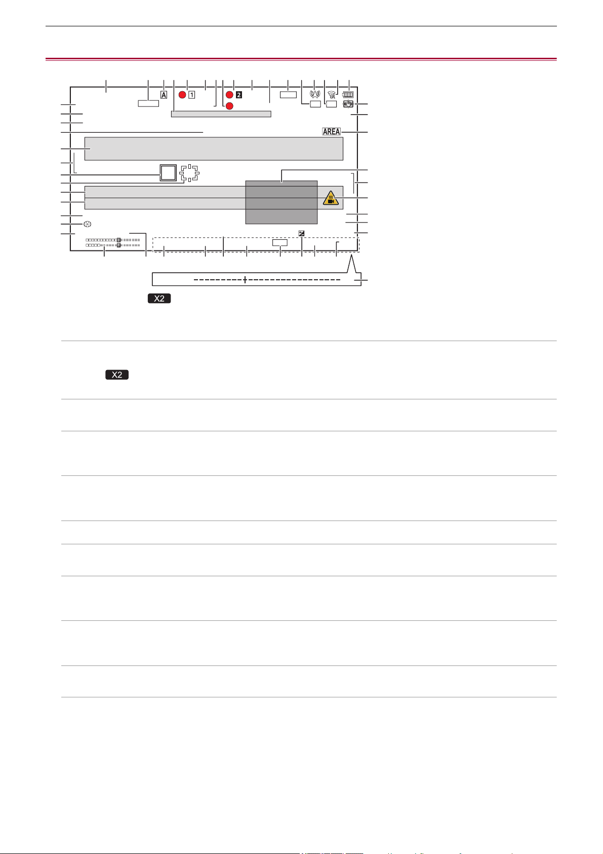
Screen status display – Screen display during shooting
245
Screen display during shooting
* Displayed when using .
1 Time code
Each time you press the <COUNTER> button, the next display is shown or it switches to no display.
[TCG ¢¢: ¢¢: ¢¢: ¢¢]:
Displays the time code. [TCR ¢¢:¢¢:¢¢:¢¢] will be displayed during playback.
• (For the )
[TCG] is displayed with black and white inverted during the slave lock into the external input time code.
[UBG ¢¢ ¢¢ ¢¢ ¢¢]:
Displays the user bits. [UBR ¢¢ ¢¢ ¢¢ ¢¢] will be displayed during playback.
[CLIP ¢: ¢¢: ¢¢: ¢¢]:
Displays the counter value of each clip. This is displayed when the [RECORDING] menu
¨ [REC COUNTER] is set to
[CLIP]. Displays the counter value of the clip being played back during playback.
[¢:¢¢:¢¢:¢¢]:
Displays the cumulative counter value from the reset position. This is displayed when the [RECORDING] menu
¨ [REC
COUNTER] ¨ [TOTAL] is set.
2 Frame rate
[¢¢fps]:
Frame rate is displayed when set to the [SCENE FILE] menu
¨ [VFR] ¨ [ON].
[S.SLOW120]:
Displayed when set to the [SYSTEM] menu ¨ [SUPER SLOW] ¨ [ON] and the [SYSTEM] menu ¨ [FREQUENCY] ¨
[59.94Hz].
[S.SLOW100]:
Displayed when set to the [SYSTEM] menu ¨ [SUPER SLOW] ¨ [ON] and the [SYSTEM] menu ¨ [FREQUENCY] ¨
[50.00Hz].
(No display):
It is not displayed when the [SCENE FILE] menu
¨ [VFR] and the [SYSTEM] menu ¨ [SUPER SLOW] are set to [OFF].
3 <AUTO/MANU> switch
Displayed when the <AUTO/MANU> switch is set to <AUTO>.
4 Message display area for stop of cooling fan
Displays a message when the cooling fan has stopped.
TCG 1 2 : 3 4 : 5 6 : 2 8
2160-59.94p
MOV HEVC 200M
A001C001
A 3200K
IP REMOTE
24dB ND:CLR 1/8000 F5.6
+1.0EVDEC 3 1 2 0 2 2 1 0 : 4 5 : 3 0
iZ50
MF99
D2x
IR
70%
HDMI INTRVLH.SENS.
ND1/16
FLUO
999min 999min
S.SLOW120
FBC
RELAY
DRS
STD
[ + ]
CH1
CH2
ICONS
VOLUME [ - ]
123 5 6 7 8 5 6 9 10 11 12
16
17 18 19 20 21
22 23 24 25
39
27
29
31
32
42
44
45
28
26
30
40
41
43
31
46
47
33
34
35
36
37
38
4 13 14 15

Screen status display – Screen display during shooting
246
5 Recording status
Displays the recording status of the memory card in card slot 1 or card slot 2.
, :
Not target for recording.
(flashing), (flashing):
Recognizing the memory card.
, :
The recording is stopped while the recording target memory card is inserted.
, :
Recording.
(Flashing red dot), (Flashing red dot):
Processing to stop the recording.
[P ], [P ]:
Recording is stopped with pre-recording is enabled and the recording target memory card is inserted.
(No display):
It is in one of the following conditions.
– A memory card has not been inserted.
– The memory card cannot be recognized.
• The following indicators are displayed in card slot 1 only.
[P]:
Pre-recording is enabled, and the memory card is not inserted in the card slot, or the memory card is not recognized.
:
The tally lamps are instructed to illuminate in red via network.
:
The tally lamps are instructed to illuminate in green via network while the recording is stopped.
The tally lamps do not illuminate green.
6 Remaining recording capacity and status of the memory card
Displays the remaining recording capacity and status of the memory card in card slot 1 or card slot 2.
[0min] to [999min]:
Remaining recording capacity (999 minutes or more is displayed as [999min])
– The display will flash when the remaining recording capacity becomes 2 minutes or less.
– The recording capacity available for simultaneous recording (recording capacity for the memory card of the 2 memory
cards with less recording capacity) is displayed when simultaneous recording is performed.
[WP]:
Write protected (the write protection switch of the memory card is set to the LOCK side)
[END]:
No remaining recording capacity (no remaining recording capacity on the memory card)
[ERR]:
A memory card that cannot record is inserted (the card is recognized but cannot record due to a format error, a card other
than a memory card being inserted, etc.)
[!SDXC]:
An SDXC memory card is not inserted in MOV recording/MP4 recording
(No display):
It is in one of the following conditions.
– A memory card has not been inserted.
– The memory card cannot be recognized.

Screen status display – Screen display during shooting
247
7 High-sensitivity mode
[H.SENS.]:
Displayed when set to the [SYSTEM] menu
¨ [SHOOTING MODE] ¨ [HIGH SENS.].
8 External equipment recording operation control status (<SDI OUT>/<HDMI> terminal)
Displays the control status of the recording start and recording stop on the external equipment connected to the <SDI OUT>
terminal and the <HDMI> terminal.
[S/H]
*
:
Recording instruction is output to the output from the <SDI OUT> terminal/<HDMI> terminal.
[S/H]
*
:
Pause instruction is output to the output from the <SDI OUT> terminal/<HDMI> terminal.
[SDI]
*
:
Recording instruction is output to the output from the <SDI OUT> terminal.
[SDI]
*
:
Pause instruction is output to the output from the <SDI OUT> terminal.
[ HDMI]:
Recording instruction is output to the output from the <HDMI> terminal.
[HDMI]:
Pause instruction is output to the output from the <HDMI> terminal.
9 Special recording function
Displays the status of special recording function.
[INTRVL]:
The interval recording is stopped.
[I-REC]:
The interval recording is in progress. (Displayed in red)
10 2-slot function
Displays the setting status of the recording function using 2 memory cards.
It is displayed with a slanted line if it is in a condition that cannot perform 2-slot recording even if each function is enabled.
[RELAY]:
When the relay recording is enabled
[SIMUL]:
When the simultaneous recording is enabled
[BACKGR]:
When the background recording is enabled
[DUAL 50M]
*
:
When dual codec recording is enabled and [DUAL CODEC SETTING] is [FHD 50Mbps]
[DUAL 8M]
*
:
When dual codec recording is enabled and [DUAL CODEC SETTING] is [FHD 8Mbps]
(No display):
During standard recording
11 Flash band compensation function
[FBC]:
Displayed when the flash band compensation function is operating.
12 Streaming status
Displays the streaming status.

Screen status display – Screen display during shooting
248
:
When the unit is connected to a device to receive the streaming video, and the streaming video is distributed
(flashing):
When the unit is being connected to a device to receive the streaming video
:
When the streaming function is enabled, it is in condition to operate properly, and the streaming video is not distributed
:
When there is an error in the streaming function and cannot operate
(No display):
When the streaming function is disabled
13 Dynamic range stretcher function/high dynamic range recording function
*
/V-Log recording function
*
[DRS]:
When the dynamic range stretcher function is working.
[HDR]
*
:
When set to the [SCENE FILE] menu
¨ [GAMMA MODE SEL] ¨ [HLG].
[VLog]
*
:
When set to the [SCENE FILE] menu
¨ [GAMMA MODE SEL] ¨ [V-Log].
14 Connection status of the wired LAN, wireless LAN or USB tethering
Displays the connection status of the wired LAN, wireless LAN or USB tethering.
:
When set to the wireless LAN and the ROP is not connected
:
When set to the wireless LAN and the ROP is connected
:
When set to the wireless LAN and the wireless LAN is not operating properly
:
When set to the wired LAN and the ROP is not connected
:
When set to the wired LAN and the ROP is connected
:
When set to the wired LAN and the wired LAN is not operating properly
*
:
When set to the USB tethering and the ROP is not connected
*
:
When set to the USB tethering and the ROP is connected
*
:
When set to the USB tethering and the USB tethering is not operating properly
(No display):
When wired LAN, wireless LAN, and USB tethering are all disabled
15 Power status
:
Displays the remaining battery level while powered with the battery. (The battery status display will change as
¨ ¨
¨ ¨ ¨ while the remaining battery level gets lower. It will flash in red when the remaining battery level is
zero.)
:
Displayed when powered with the AC adaptor.

Screen status display – Screen display during shooting
249
16 Audio level meter
Displays the audio level meter.
A white frame is displayed at the position of the reference level set in the [AUDIO] menu
¨ [REC CH SETTINGS] ¨ [HEAD
ROOM]. (Eighth from the left when set to [20dB], ninth from the left when set to [18dB], and 12th from the left when set to
[12dB])
:
Displayed when audio cannot be recorded. (When super slow is enabled, etc.)
17 Luminance of Y GET
Displays the luminance level in 0 % through 109 % when the Y GET function is operating.
18 Gain
Displays the gain value.
[AGC]:
Displayed when the auto gain control is operating.
[SG]:
Displayed when [SUPER GAIN] is working.
[SG+]:
Displayed when [SUPER GAIN+] is working.
19 ND filter
Displays the transmittance of the selected ND filter.
[ND1/64]:
Reduces the amount of light entering the MOS sensor to 1/64.
[ND1/16]:
Reduces the amount of light entering the MOS sensor to 1/16.
[ND1/4]:
Reduces the amount of light entering the MOS sensor to 1/4.
[ND:CLR]:
The ND filter is not used.
20 Date and time information
Displays the date and time information. It is not displayed when the time stamp function is enabled.
The display contents follow the setting in the [VIDEO OUT/LCD/VF] menu
¨ [INDICATOR] ¨ [DATE/TIME]. (Î[DATE/
TIME]: 105
)
• The display order for the year, month, and date follows the setting in the [OTHERS] menu
¨ [CLOCK] ¨ [DATE
FORMAT].
– Displays in the yyyy mmm dd hh:mm:ss format when set to [Y-M-D].
– Displays in the mmm dd yyyy hh:mm:ss format when set to [M-D-Y].
– Displays in the dd mmm yyyy hh:mm:ss format when set to [D-M-Y].
mmm:
Month (JAN (January), FEB (February), MAR (March), APR (April), MAY (May), JUN (June), JUL (July), AUG (August), SEP
(September), OCT (October), NOV (November), DEC (December))
dd: Date
yyyy: Year
hh: Hour
mm: Minute
ss: Second

Screen status display – Screen display during shooting
250
21 Shutter speed
Displays the shutter speed.
[A.SHTR]:
Displayed when the auto shutter is operating.
22 Auto iris control status
Displays the control status of the auto iris.
[STD]:
Standard auto iris control
[SPOT]:
Auto iris control for spot light
[BACK]:
Auto iris control for the backlight compensation
23 AE level
Displays the exposure compensation value.
24 Iris
Displays the iris value.
25 Zoom
Displays the zoom value.
The display of the zoom value follows the setting in the [VIDEO OUT/LCD/VF] menu ¨ [INDICATOR] ¨ [ZOOM/FOCUS].
• Displays in the position value from [00] to [99] when set to [NUMBER].
• Displays in millimeter unit when set to [mm/feet] or [mm/m].
• Displays [i] when [i.ZOOM] is enabled.
• [i] is displayed with black and white inverted when [i.ZOOM] is operating.
• [Z] is displayed with black and white inverted when [FAST ZOOM] is enabled.
26 System resolution/system frequency
Displays the system resolution and the system frequency set in the [SYSTEM] menu
¨ [REC FORMAT].
• [2160-59.94p], [2160-50.00p], [2160-29.97p], [2160-25.00p], [2160-23.98p], [1080-59.94p], [1080-50.00p], [1080-29.97p],
[1080-25.00p], [1080-23.98p], [1080-59.94i], [1080-50.00i], [720-59.94p], [720-50.00p]
27 Recording format
Displays the file format and the recording codec set in the [SYSTEM] menu
¨ [FILE FORMAT] and [REC FORMAT].
• [MOV 420 150M], [MOV 420 100M], [MOV 422 150M], [MOV 422 100M], [MOV 422 50M], [MOV HEVC 200M], [MOV
HEVC 150M], [MOV HEVC 100M], [MOV ALL-I 200M], [MOV ALL-I 100M]
• [MP4 420 72M], [MP4 420 50M], [MP4 HEVC 100M], [MP4 HEVC 72M]
• [AVCHD PS], [AVCHD PH], [AVCHD HA], [AVCHD PM]
28 Clip name
Displays the name of the clip being recorded with up to 8 characters from the beginning.
29 Recommended ND filter
Displays the ND filter recommended in the current shooting condition.
30 Message display area
Displays messages, such as the status of the camera and warnings.
Displays the warning status of the unit in the STATUS screen for the mode check.
31 Level gauge
Tilt in horizontal direction or vertical direction can be checked.
• This is not output externally to the TV/monitor. View it on the LCD monitor/viewfinder of this unit.
32 Main face frame (orange)/Face detection frame (white)
Displayed when a face has been detected while the face detection AE&AF function is operating.
33 Tracking frame (green)
Displayed when a subject has been touched while the face detection AE&AF function is operating. The function switches to
the tracking AE&AF function.
Screen status display – Screen display during shooting
251
34 Error display of auto white balance
Displays the error status of the auto white balance.
35 Error display of auto black balance
Displays the error status of the auto black balance.
36 Remote control status in an IP connection
[IP REMOTE]:
Displayed when the remote control is possible in the IP connection.
[IP REMOTE] (flashing):
Displayed when waiting for the connection in the IP connection.
37 Multi manual function
Displays the contents of the multi manual function. (ÎMulti manual function: 221).
38 Color temperature
Displays the white balance setting value (Ach/Bch/Preset) and color temperature. This is not displayed when IR recording is
enabled.
[ATW]:
Displayed when the auto tracking white balance is operating.
[LOCK]:
Displayed when the auto tracking white balance is locked.
39 Optical image stabilizer function
:
Displayed when the optical image stabilizer function is operating.
:
Displayed when the hybrid optical image stabilizer function is operating.
40 Scene file name
Displays the name of the selected scene file.
41 Area mode function, AF area width adjustment function, face detection/tracking AE&AF function
[AREA]:
Displayed when the area mode function is operating.
[AF-AREA]:
Displayed when the AF area width adjustment function is operating.
[FACE]:
Displayed when the face detection AE&AF function is working.
[TRACK]:
Displayed when the tracking AE&AF function is working.
42 Waveform monitor
Displays the video status in waveform or vector.
• This is not output externally to the TV/monitor. View it on the LCD monitor/viewfinder of this unit.
43 Temperature increase warning
[]:
Displayed when the temperature of this unit has increased. If you continue to use the unit like this, a message indicating that
the unit cannot be used will be displayed and you will be unable to use recording functions and network functions. Wait until
the temperature of the unit decreases.
44 IR recording
[IR]:
Displayed when the IR recording is enabled.

Screen status display – Screen display during shooting
252
45 Digital zoom
Displays the digital zoom ratio.
[D2×]: 2 times
[D5×]: 5 times
[D10×]: 10 times
46 Focus
Displays the focus value.
The display of the focus value follows the setting in the [VIDEO OUT/LCD/VF] menu
¨ [INDICATOR] ¨ [ZOOM/FOCUS].
• Displays in the position value from [00] to [99] when set to [NUMBER].
• Displays in feet unit when set to [mm/feet].
• Displays in meter unit when set to [mm/m].
[]:
Displayed when the focus macro is enabled.
[AF]:
Displayed when set to auto focus mode. Displayed with black and white inverted when focus macro is operating.
[MF]:
Displayed when set to manual focus mode. Displayed with black and white inverted when focus macro is operating.
47 Audio monitor volume adjustment
Displayed when the zoom lever or the multidial is used to adjust the volume of the speaker or headphones. The display is
cleared approximately 3 seconds after the operation.

Screen status display – Screen display during playback
253
Screen display during playback
1 Time code display
Each time you press the <COUNTER> button, the display changes in the order [TCR ¢¢:¢¢:¢¢:¢¢], [UBR ¢¢ ¢¢ ¢¢
¢¢], [CLIP ¢: ¢¢: ¢¢: ¢¢], no display.
2 Clip name
Displays the name of the clip being played back with up to 8 characters from the beginning.
3 Playback status
Displays the status of playback. Displays only during playback.
: Stop
: Playback
: Pause
: Frame-by-frame rewind
: Frame-by-frame
: Fast-forward playback (10× speed)
: Fast-forward playback (20× speed)
: Fast-reverse playback (10× speed)
: Fast-reverse playback (20× speed)
: Slow playback
: Reverse slow playback
4 Still picture recording icon
Touching the icon while playing back or while paused records the scene as a still picture.
5 Direct playback bar
Displays the general position that is being played back.
6 Playback navigation icon
Operates by touching the icon.
: Fast-forward playback
: Fast-reverse playback
: Stop
: Playback/pause
TCR 12:59:59:23 A001C001
3
5
6
1 2
4
CH1
CH2

Screen status display – Checking and displaying shooting status
254
Checking and displaying shooting status
The screen to check the setting and status of the unit can be displayed.
Press the <DISP/MODE CHK> button while the camera image screen is displayed to hide most of the items.
Press the <DISP/MODE CHK> button for 1 second or more while the camera image screen is displayed to display the STATUS
screen of the mode check and check the shooting status.
• For details about each item that can be displayed in the mode check (
ÎMode check display: 256).
The following table indicates each item to display/hide in each screen.
• “3” indicates displaying and “—” indicates hiding.
• You can select to display or hide each item in the [VIDEO OUT/LCD/VF] menu
¨ [INDICATOR].
*1 This is not displayed in the status where / is not displayed.
*2 Displays when the remaining recording capacity of the memory card or remaining battery level gets low.
*3 The display position differs in the playback screen. (
ÎScreen display during playback: 253).
*4 Displays when the multidial is pressed. The display is cleared approximately 3 seconds after the operation.
No Item
Camera image
screen
When the <DISP/
MODE CHK> button is
pressed
STATUS
Playback
screen
1 Time code 3333
2 Frame rate 3 — 3 —
3 <AUTO/MANU> switch 3 — 3 —
4
Message display area for stop of cooling
fan
3333
5 Recording status 33
*1
3 —
6
Remaining recording capacity and status
of the memory card
3 —
*2
3
*2
—
7 High-sensitivity mode 3 — 3 —
8
External equipment recording operation
control status (<SDI OUT>/<HDMI>
terminal)
3 — 3 —
9 Special recording function 3 — 3 —
10 2-slot function 3 — 3 —
11 Flash band compensation function 3 — 3 —
12 Streaming status 3 — 3 —
13
Dynamic range stretcher function/high
dynamic range recording function/V-Log
recording function
3 — 3 —
14
Connection status of the wired LAN,
wireless LAN or USB tethering
3 — 3 —
15 Power status 3 —
*2
33
16 Audio level meter 3 — 33
17 Luminance of Y GET 333—
18 Gain 3 — 3 —
19 ND filter 3 — 3 —
20 Date and time information 3 — 3 —
21 Shutter speed 3 — 3 —
22 Auto iris control status 3 — 3 —
23 AE level 3 — 3 —
24 Iris 3 — 3 —
25 Zoom 3 — 3 —
26 System resolution/system frequency 3 — 3 —
27 Recording format 3 — 3 —
28 Clip name 3 — 33
*3
29 Recommended ND filter 333—
30 Message display area 3333
31 Level gauge 333—
32
Main face frame (orange)/Face detection
frame (white)
333—
33 Tracking frame (green) 333—
34 Error display of auto white balance — — 3 —

Screen status display – Checking and displaying shooting status
255
35 Error display of auto black balance — — 3 —
36 Remote control status in an IP connection — — 3 —
37 Multi manual function 3 —
*4
3 —
38 Color temperature 3 — 3 —
39 Optical image stabilizer function 3 — 3 —
40 Scene file name 3 — 3 —
41
Area mode function, AF area width
adjustment function, face detection/
tracking AE&AF function
3 — 3 —
42 Waveform monitor 33——
43 Temperature increase warning 333—
44 IR recording 3 — 3 —
45 Digital zoom 3 — 3 —
46 Focus 3 — 3 —
47 Audio monitor volume adjustment 3333

Screen status display – Mode check display
256
Mode check display
The unit’s settings and status can be displayed on the viewfinder or LCD monitor screen for check.
Press the <DISP/MODE CHK> button for 1 second or more while displaying the camera image screen to display the STATUS
screen of the mode check.
Each time you press the <DISP/MODE CHK> button, the display switches in the order STATUS screen, FUNCTION screen,
AUDIO screen, SWITCH screen, NETWORK screen, camera image screen.
Each screen of the mode check is displayed for approximately 5 seconds.
The screen does not switch while the <DISP/MODE CHK> button is pressed.
Press the <EXIT> button while each screen is displayed to return to the camera image screen.
FUNCTION screen
Displays the video output settings and information of the recording media.
For the
•
The mode check screen cannot be displayed even when you press the <DISP/MODE CHK> button in the following case:
– When the [VIDEO OUT/LCD/VF] menu
¨ [LCD] ¨ [SELF SHOOT] ¨ [MIRROR] is set and the LCD monitor is rotated
toward the lens (when mirror shooting)
Item Description
[VIDEO OUT] [VIDEO OUT SEL] Displays the external output destination.
[SDI+HDMI]:
When [VIDEO OUT/LCD/VF] menu
¨ [VIDEO OUT SEL] ¨ [SDI + HDMI
OUTPUT] is set to [ON]
[SDI]:
When [VIDEO OUT/LCD/VF] menu
¨ [VIDEO OUT SEL] ¨ [EXTERNAL
OUT SEL] is set to [SDI]
[HDMI]:
When [VIDEO OUT/LCD/VF] menu
¨ [VIDEO OUT SEL] ¨ [EXTERNAL
OUT SEL] is set to [HDMI]
[SDI OUT FORMAT] Displays with [1920×1080p]/[1920×1080i]/[1920×1080PsF]/[1280×720p] the
signals output through the <SDI OUT> terminal.
[SDI OUT CHAR] Displays with [ON]/[OFF] whether the characters output through the
<SDI OUT> terminal are superimposed.
[HDMI OUT FORMAT] Displays with [3840×2160p]/[3840×2160p(420/8bit)]/[1920×1080p]/
[1920×1080i]/[1280×720p]/[720×480p]/[720×576p] the signals output through
the <HDMI> terminal.
[HDMI OUT CHAR] Displays with [ON]/[OFF] whether the characters output through the <HDMI>
terminal are superimposed.
[HDR/SDR]
(When [SCENE FILE] menu
¨ [GAMMA MODE SEL] is set
to anything other than [V-Log])
[SDI OUT] Images output from the <SDI OUT> terminal are displayed with [HDR]/[SDR].
• Displays with [SDR] in the following cases:
– When [SCENE FILE] menu
¨ [GAMMA MODE SEL] is set to anything
other than [HLG]
– When [VIDEO OUT/LCD/VF] menu
¨ [SDI SETTING] ¨ [SDI OUT
HDR] is set to anything other than [HDR]
• Displays with [---] in the following case:
– When the [VIDEO OUT/LCD/VF] menu
¨ [VIDEO OUT SEL] setting is
HDMI output
[HDMI OUT] Images output from the <HDMI> terminal are displayed with [HDR]/[SDR].
• Displays with [SDR] in the following cases:
– When [SCENE FILE] menu
¨ [GAMMA MODE SEL] is set to anything
other than [HLG]
– When [VIDEO OUT/LCD/VF] menu
¨ [HDMI SETTING] ¨ [HDMI OUT
HDR] is set to anything other than [HDR]
• Displays with [---] in the following case:
– When the [VIDEO OUT/LCD/VF] menu
¨ [VIDEO OUT SEL] setting is
SDI output
[LCD/VF] Images output from the LCD monitor and viewfinder are displayed with
[HDR]/[SDR].

Screen status display – Mode check display
257
[V-Log/709]
(When [SCENE FILE] menu
¨ [GAMMA MODE SEL] is set
to [V-Log])
[SDI OUT] Images output from the <SDI OUT> terminal are displayed with [V-Log]/
[V-709].
• Displays with [V-709] in the following case:
– When [VIDEO OUT/LCD/VF] menu
¨ [SDI SETTING] ¨ [SDI OUT
V-Log] is set to anything other than [V-Log]
• Displays with [---] in the following case:
– When the [VIDEO OUT/LCD/VF] menu
¨ [VIDEO OUT SEL] setting is
HDMI output
[HDMI OUT] Images output from the <HDMI> terminal are displayed with [V-Log]/[V-709].
• Displays with [V-709] in the following case:
– When [VIDEO OUT/LCD/VF] menu
¨ [HDMI SETTING] ¨ [HDMI OUT
V-Log] is set to anything other than [V-Log]
• Displays with [---] in the following case:
– When the [VIDEO OUT/LCD/VF] menu
¨ [VIDEO OUT SEL] setting is
SDI output
[LCD/VF] Images output from the LCD monitor and viewfinder are displayed with
[V-Log]/[V-709].
[CARD STATUS] — Displays the status, remaining recording capacity, and the total capacity of
the memory card inserted in the card slot.
The status of the memory card that is displayed are following types.
[NO CARD]:
Memory card is not inserted.
[UNSUPPORTED]:
Memory card is not supported.
[FORMAT ERROR]:
Memory card cannot be used. (Format error)
[PROTECTED]:
It is write protected. (The write-protection switch of the memory card is set to
the LOCK side)
[NO REMAIN]:
There is no remaining recording capacity.
[NOT SDXC]:
SDXC memory card is not inserted in the MOV recording/MP4 recording.
Cases other than above:
The remaining recording capacity is displayed in 0 % through 100 %.
[TOTAL] Displays the remaining recording capacity/total capacity of the memory cards
in the card slot 1 and the card slot 2.
[SLOT1] Displays the status and remaining recording capacity/total capacity of the
memory card in card slot 1.
[SLOT2] Displays the status and remaining recording capacity/total capacity of the
memory card in card slot 2.
Screen status display – Mode check display
258
For the
AUDIO screen
Displays the audio input/output settings and the audio level meter.
Item Description
[VIDEO OUT] [VIDEO OUT FORMAT] Displays with [3840×2160p]/[3840×2160p(420/8bit)]/[1920×1080p]/
[1920×1080i]/[1280×720p]/[720×480p]/[720×576p] the signals output through
the <HDMI> terminal.
[VIDEO OUT CHAR] Displays with [ON]/[OFF] whether the characters output through the <HDMI>
terminal are superimposed.
[CARD STATUS] — Displays the status, remaining recording capacity, and the total capacity of
the memory card inserted in the card slot.
The status of the memory card that is displayed are following types.
[NO CARD]:
Memory card is not inserted.
[UNSUPPORTED]:
Memory card is not supported.
[FORMAT ERROR]:
Memory card cannot be used. (Format error)
[PROTECTED]:
It is write protected. (The write-protection switch of the memory card is set to
the LOCK side)
[NO REMAIN]:
There is no remaining recording capacity.
[NOT SDXC]:
SDXC memory card is not inserted in the MOV recording/MP4 recording.
Cases other than above:
The remaining recording capacity is displayed in 0 % through 100 %.
[TOTAL] Displays the remaining recording capacity/total capacity of the memory cards
in the card slot 1 and the card slot 2.
[SLOT1] Displays the status and remaining recording capacity/total capacity of the
memory card in card slot 1.
[SLOT2] Displays the status and remaining recording capacity/total capacity of the
memory card in card slot 2.
Item Description
[AUDIO] [AUDIO OUT] Displays with [CH1]/[CH2]/[CH1/2 STEREO]/[CH1/2 MIX] the audio channel
format output from the headphone jack and the built-in speaker.
[SELECT] [CH1]/[CH2] Displays the audio recorded to each channel with [INT(L)]/[INT(R)]/[INPUT1]/
[INPUT2].
[LINE/MIC] [CH1]/[CH2] Displays the audio input signal for each channel with [LINE]/[MIC]/
[MIC+48V].
When either [INT(L)] or [INT(R)] is selected as the recorded audio, [---] is
displayed.
[LEVEL] [CH1]/[CH2] Displays the adjustment method of the recording level of the audio for each
channel with [AUTO]/[MANU].
[LIMITER] [CH1]/[CH2] Displays enable/disable of limiter for each channel with [ON]/[OFF].
Displays [---] when the adjustment method of the recording level of the audio
is set to [AUTO].
[LOWCUT] [CH1]/[CH2] Displays enable/disable of low-cut filter for each channel with [ON]/[OFF].
Audio level meter Enlarges the display of the audio level meter displayed on the camera image
screen.
Screen status display – Mode check display
259
SWITCH screen
Displays the values assigned to the USER switch, super gain, and white balance.
NETWORK screen
Displays the settings of the network function.
*1 Displayed when using .
*2 Displayed when using .
Item Description
[USER SW] [1] to [9] Displays the function assigned to <USER1> through <USER9> buttons.
[OTHER ASSIGN] [S.GAIN] Displays the list of gain values assigned as a super gain.
[WHITE BAL A] Displays the color temperature of the “Ach” of the white balance.
Displays [ATW] when the auto tracking white balance function is assigned.
[WHITE BAL B] Displays the color temperature of the “Bch” of the white balance.
Displays [ATW] when the auto tracking white balance function is assigned.
[WHITE BAL PRST] Displays the color temperature assigned to the “Preset” of white balance.
Displays [ATW] when the auto tracking white balance function is assigned.
Color temperature and [VAR] are displayed when “VAR” is assigned.
Item Description
[NETWORK] [DEVICE SEL] Displays the device used for network connection in [LAN] (wired LAN)
*1
/
[USB-LAN] (wired LAN)
*2
/[WLAN] (wireless LAN)/[USB TETHERING] (USB
tethering)
*1
/[OFF] (Off).
[NETWORK FUNC] Displays the network function of the unit with [STREAMING]/[OFF].
[STRM PROTOCOL] Displays the [NETWORK] menu
¨ [STREAMING] ¨ [STREAMING
PROTOCOL] setting value as [RTMP(S)]/[RTSP].
[STRM FORMAT] Displays the streaming format.
It is not displayed when set to the [NETWORK] menu
¨ [NETWORK FUNC]
¨ [OFF].
[IP REMOTE] Displays enable/disable of the IP remote function with [ENABLE]/[DISABLE].
[IPv4 ADDRESS] Displays the IP address of IPv4.
It is not displayed when set to the [NETWORK] menu
¨ [DEVICE SEL] ¨
[OFF].
[IPv6 ADDRESS] Displays the IP address of IPv6.
• (For the )
[DISABLE] is displayed when the [NETWORK] menu
¨ [LAN IPv6
SETTING]
¨ [ENABLE/DISABLE] ¨ [DISABLE] is set.
It is not displayed when the [NETWORK] menu
¨ [DEVICE SEL] is set to
anything other than [LAN].
• (For the )
[DISABLE] is displayed when the [NETWORK] menu
¨ [USB-LAN IPv6
SETTING]
¨ [ENABLE/DISABLE] ¨ [DISABLE] is set.
It is not displayed when the [NETWORK] menu
¨ [DEVICE SEL] is set to
anything other than [USB-LAN].

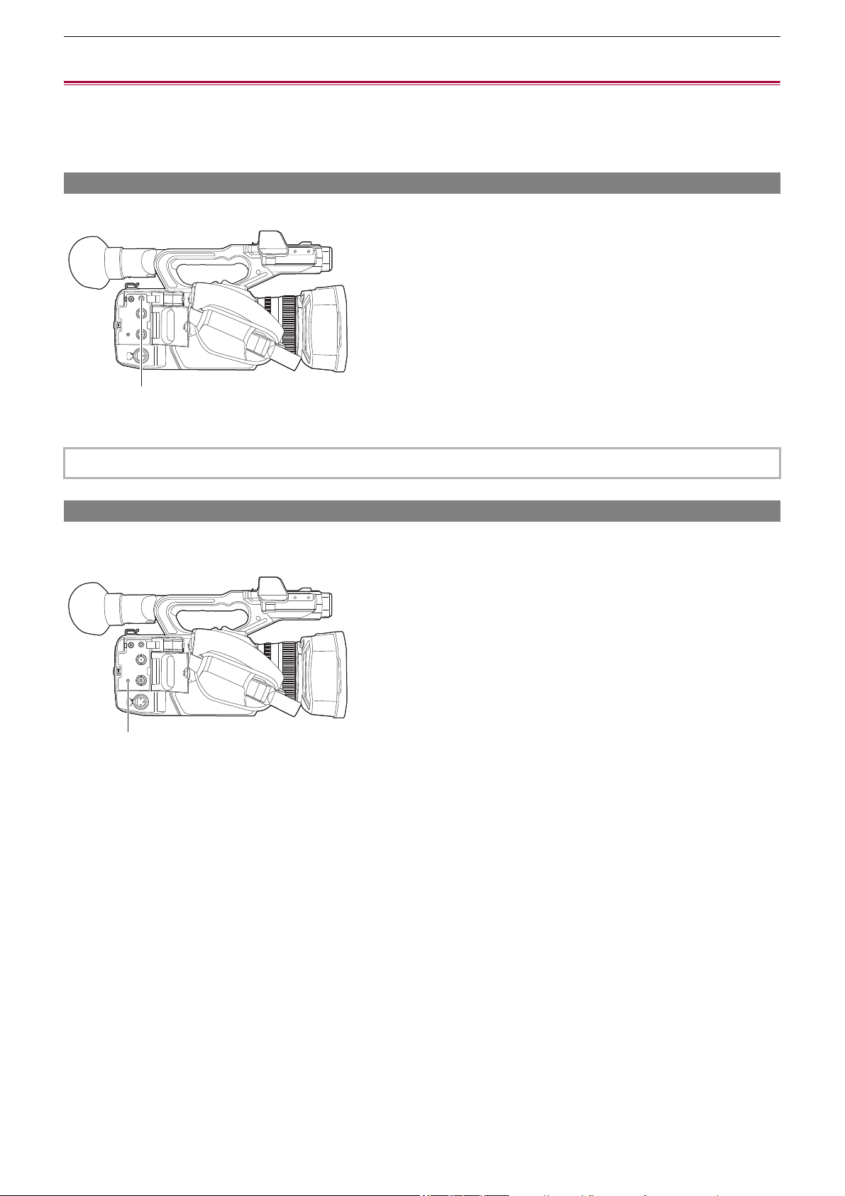
Connecting to External Devices – Connecting with headphones and TV/monitor
261
Connecting with headphones and TV/monitor
≥Headphones: 261
≥Remote control: 261
≥TV/monitor: 262
Headphones
Headphones (commercially-available) can be connected to the headphone terminal (3.5 mm diameter stereo mini jack).
(A) Headphone terminal
Remote control
Connect the remote control unit (commercially-available) to the <REMOTE> terminal (2.5 mm diameter super mini jack) to
operate some of the functions remotely.
(A) <REMOTE> terminal
• Audio is not output from the built-in speaker when headphones are connected to the headphone terminal.
(A)
(A)

Connecting to External Devices – Connecting with headphones and TV/monitor
262
TV/monitor
A TV or monitor can be connected as shown in the following figure.
• When using , use a BNC cable (<SDI OUT> terminal) to connect a TV/monitor.
(A) (For the )
BNC cable (commercially-available)
(B) HDMI cable (commercially-available)
(C) TV/Monitor
• By connecting this unit to a 4K video compatible TV/monitor using an HDMI cable, and playing back clips recorded with a
recording format that has a resolution of UHD (3840×2160), you can enjoy the finely detailed video provided by 4K videos. If
the TV/monitor is not compatible with 4K video, you can set [HDMI OUT FORMAT]/[OUT FORMAT] and reduce the output
resolution for playback. (
ÎFormat that can be output from the HDMI terminal: 240)
When using a DVI converter, etc., to connect an HDMI cable to this unit, make sure that you connect last to the
<HDMI> terminal on this unit. Connecting first to the <HDMI> terminal on this unit may cause a malfunction.
• VIERA Link is not supported on the unit. Note that the VIERA Link of other device may not properly operate when
connected to the VIERA Link compatible device with a HDMI cable (commercially-available).
• The SD resolution signal output from the <HDMI> terminal is output as a progressive signal (480P, 576P).
• (For the )
Use a commercially-available 5C-FB or equivalent double-shielded cable for the BNC cable.
• Use a commercially-available Premium High Speed HDMI cable.
• When this unit is connected to a TV/monitor while displaying the camera image screen, there may be some howling
*
caused. Press the <THUMBNAIL> button to switch to the thumbnail screen first before connecting this unit to a TV/monitor.
* The microphone can pick up the sounds coming from the speaker which can cause unusual sounds.
SDI OUT
(B)
(C)
(A)
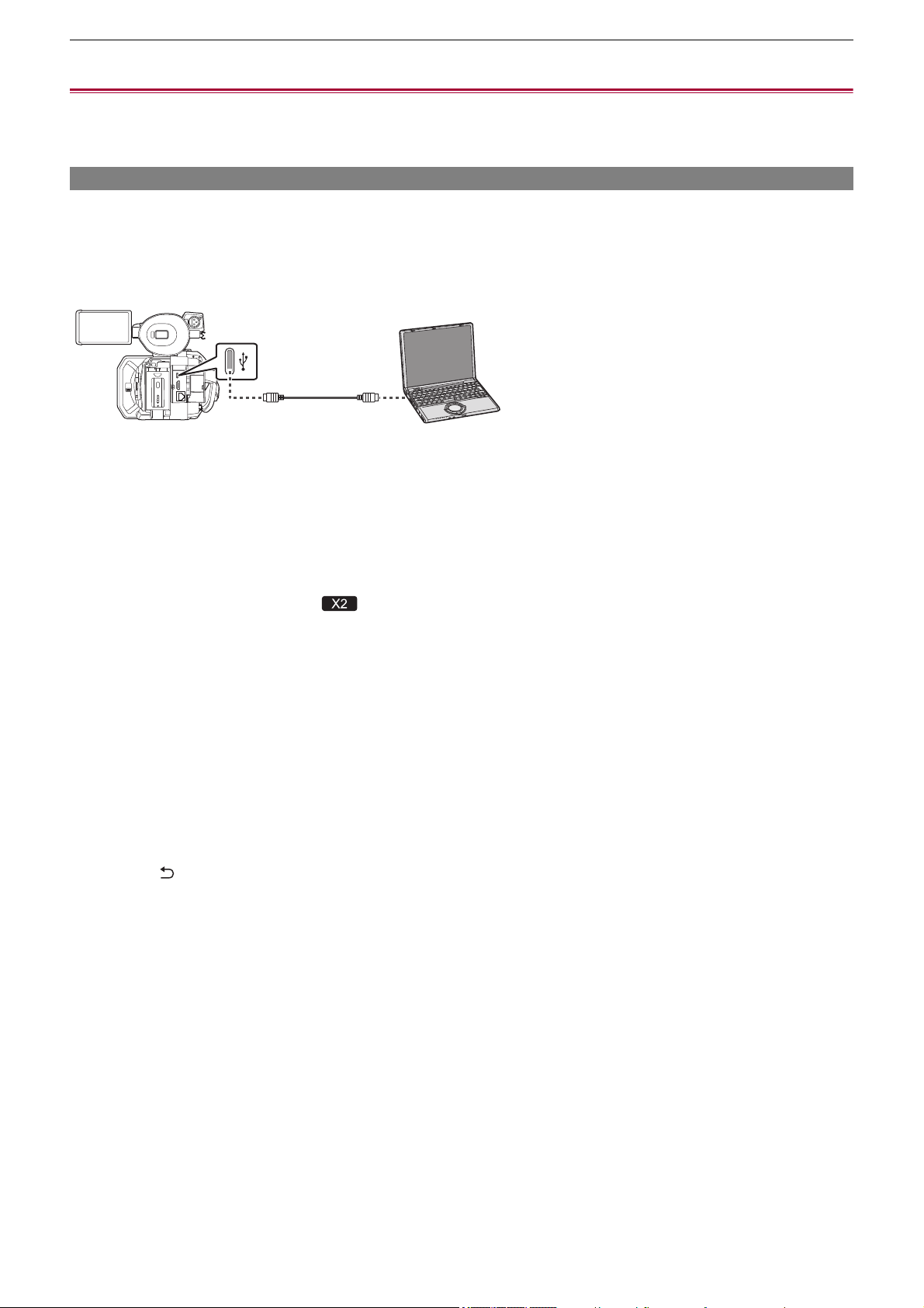
Connecting to External Devices – Connection function via the USB terminal
263
Connection function via the USB terminal
≥Connection with a computer in card reader mode: 263
≥Operating environment (mass storage): 265
Connection with a computer in card reader mode
Connect the unit to a computer via the USB cable to use the unit as a card reader for the memory card.
• This unit supports USB3.1 Gen1.
Connecting to a computer
(A) USB terminal (type C)
(B) USB cable (commercially-available)
(C) Computer
1
Connect the USB cable to the USB terminal.
2
Select the [NETWORK] menu ¨ [DEVICE SEL] ¨ [LAN]
*
, [WLAN] or [OFF].
* Available for setting when using .
3
Select the [OTHERS] menu ¨ [USB DEVICE] ¨ [CARD READER MODE] ¨ [YES].
During USB connection, [USB connected. Please operate via PC.] is displayed in the center of the viewfinder or LCD
monitor.
If the USB connection is being moved or it is not connected properly, [Connect this unit to PC using USB cable.] is
displayed.
• When using the battery, the LCD monitor turns off after about 5 seconds. Touch the screen to turn the LCD monitor on.
4
Exit the card reader mode.
There are following methods.
• Turn off the unit.
• Press the <EXIT> button.
• Press the multidial.
• Touch [ ]
After exiting the card reader mode, returns to camera shooting status in approximately 5 seconds.
(A)
(B)
(C)
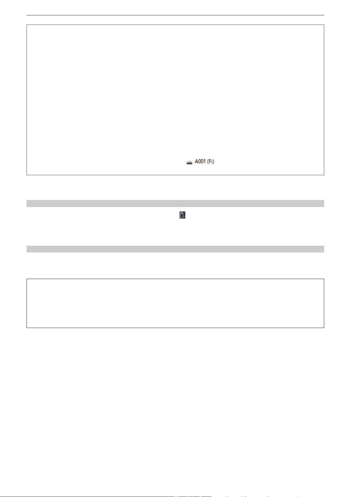
Connecting to External Devices – Connection function via the USB terminal
264
To disconnect USB cable safely
For Windows
1
On the screen of the computer, select the icon in the task tray, then deselect the
model number of this unit. (For example: “HC-X2”, etc.)
• Depending on your computer’s settings, this icon may not be displayed.
For Mac
1
Move the icon of the volume name of the memory card (for example: “A001”, etc.)
displayed on the desktop to “Trash”, then disconnect the USB cable.
• You can also either press the USER button assigned to [CARD READER MODE] or touch the USER button icon to switch
to the card reader mode.
• A USB cable is not supplied with this unit. When using a commercially-available USB cable, use a USB Type-C cable that
conforms with USB3.1 and that is a shielded product with a ferrite core. We recommend using a cable that is within 1.5 m
(approx. 4.9 feet) where possible.
• You cannot write data to the memory cards of this unit from a computer.
• When connecting the unit to a computer via USB, ensure that no other device is connected to the computer via USB.
• Do not remove the memory card when connecting the unit via USB.
• The card access lamps while connected to USB will turn off unless accessing.
• When the unit is operating in the card reader mode, it cannot perform shooting, recording, and playback, and thumbnail
operations cannot be performed on clips.
• When the unit is operating in the card reader mode, the remaining recording capacity and status of the memory card are not
displayed. Also, video/audio cannot be output or displayed.
• The LCD monitor lights up by touching the monitor if it has turned out to save energy.
• When reading or writing the data on a memory card with a computer, the SD card slot in the computer or the SD card
reader/writer you are using may not support the memory card.
• When the unit is connected to a computer, it is recognized as an external drive.
It is displayed on a computer as a removable drive (for example: ).
• For example memory card folder structures (
ÎFolder structure example of a memory card: 50)
About the screen indication of the unit
• The card 1 access lamp or card 2 access lamp flashes while this unit is being accessed. Do not disconnect the USB cable,
battery, or AC adaptor while the unit is being accessed.
• If the screen does not change when the unit is operated while connected to a computer, disconnect the battery and/or AC
adaptor, wait approximately 1 minute, reconnect the battery and/or AC adaptor, wait approximately 1 minute again, and
then turn the unit back on. (Data may be destroyed when above operation is performed while accessing the memory card.)

Connecting to External Devices – Connection function via the USB terminal
265
Operating environment (mass storage)
• Even if the system requirements mentioned in these operating instructions are fulfilled, some computer’s cannot be used.
• The USB equipment operates with the driver installed as standard in the OS.
For Windows
OS:
Windows 11 (64 bit)
Windows 10 (32 bit/64 bit)
Windows 8.1 (32 bit/64 bit)
CPU:
1 GHz or higher, 32 bit or 64 bit processor
RAM:
2 GB or more (64 bit)/1 GB or more (32 bit)
Interface:
USB port
Other requirements:
Mouse or equivalent pointing device
For Mac
OS:
macOS v10.15
CPU:
Intel Core 2 Duo or better
RAM:
2 GB or more
Interface:
USB port
Other requirements:
Mouse or equivalent pointing device

Connecting to External Devices – Remote operation by iPhone/iPad or Android terminal
266
Remote operation by iPhone/iPad or Android terminal
This unit can connect to wireless LAN devices via a network.
Some of the functions can be remotely operated by connecting the unit with iPhone/iPad or Android terminal with the HC ROP
app installed. (
ÎConnecting to the iPhone/iPad or Android terminal: 278)

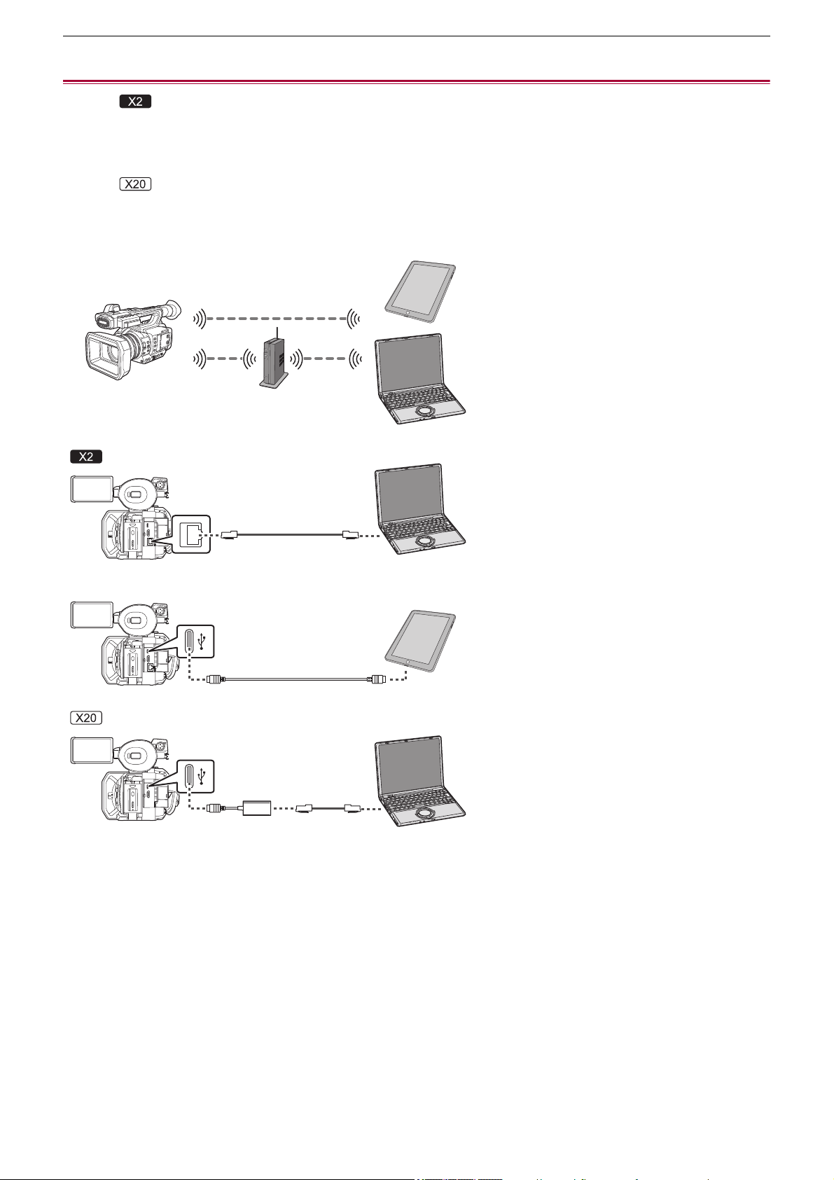
Network Connection – Network connection
268
Network connection
(For the )
The camera can be connected to a network via wired LAN, wireless LAN, and USB tethering.
• Connect a LAN cable to the <LAN> terminal to use wired LAN.
• When using USB tethering, connect an iPhone/iPad or Android device to the USB terminal using a USB cable.
(For the )
The camera can be connected to a network via wired LAN and wireless LAN.
• When using wired LAN, connect a USB ethernet adaptor (commercially available) to the USB terminal, then connect a LAN
cable to the LAN terminal on the USB ethernet adaptor.
(A) Wireless access point
(B) Device with wireless LAN
(C) <LAN> terminal
(D) Device with LAN
(E) USB terminal
(F) USB tethering device
(G) USB ethernet adaptor (commercially-available)
≥Available functions: 269
≥About the wireless LAN function on this unit: 269
≥Preparing for connection: 270
(A)
(G)
(E)
(D)
(D)
(F)
(B)
(E)
(C)

Network Connection – Network connection
269
Available functions
When the unit is connected to a network, the following functions are available.
•
Connecting to HC ROP app
• Streaming function
About the wireless LAN function on this unit
This product cannot be connected directly to the communication lines (including public wireless LAN) of
telecommunications companies (mobile communications companies, fixed-line communications companies,
Internet providers, etc.).
Be sure to connect via a router, etc., when connecting this product to the Internet.
Use this unit as a wireless LAN device
When using equipment or computer systems that require more reliable security than wireless LAN devices, ensure that the
appropriate measures are taken for safety designs and defects for the systems used.
Panasonic will not take any responsibility for any damage that arises when using this unit for any purpose other than as a
wireless LAN device.
Use of the wireless LAN function of this unit is presumed to be in countries where this unit is sold
There is the risk that this unit violates the radiowave regulations if used in countries other than those where this unit is sold, and
Panasonic takes no responsibility for any violations.
There is the risk that data sent and received via radio waves may be intercepted
Please note that there is the risk that data sent and received via radio waves may be intercepted by a third party.
Do not use this unit in areas with magnetic fields, static electricity or interference
•
Do not use this unit in areas with magnetic fields, static electricity or interference, such as near microwave ovens. Radio
waves may not reach this unit.
• Using this unit near devices such as cordless telephones or any other wireless LAN device that use the 2.4 GHz radio wave
band may cause a decrease in performance in both devices.
Do not connect to the wireless network you are not authorised to use
When this unit utilises its wireless LAN function, wireless networks will be searched automatically.
When this happens, wireless networks that you are not authorised to use (SSID
*
) may be displayed, however do not attempt to
connect to the network as it may be considered as unauthorised access.
* SSID refers to the name of device that is used to identify a network over a wireless LAN connection. If the SSID matches for
both devices, transmission is possible.
Before use
To use the wireless LAN function on this unit, you need a wireless access point or a device connected that has wireless LAN
functionality.
For the operations and settings of the device you are using, such as iPhone/iPad or Android handset, refer to the operating
instructions for your device.
This unit is WPS-compatible
WPS (Wi-Fi Protected Setup
™
) is a function that allows you to easily set up a connection with a wireless LAN device and make
security-related settings.
Network Connection – Network connection
270
Preparing for connection
For the wired LAN
(For the )
1
Connect a LAN cable (commercially available) to the <LAN> terminal on this unit.
Connect the other end of the LAN cable to a wired LAN compatible device.
(For the )
1
Connect a USB ethernet adaptor (commercially available) to the USB terminal on this
unit.
2
Connect a LAN cable (commercially available) to the USB ethernet adaptor
(commercially available) and the wired LAN compatible device.
For USB tethering
1
Connect a USB cable (commercially available) to the USB terminal on this unit and
the terminal to be used for USB tethering (iPhone/iPad or Android terminal).
Push the cable in firmly all the way.
• This unit cannot be connected to wireless LAN devices via public wireless LAN environments.
• The wireless access point must be compatible with IEEE802.11b, IEEE802.11g, or IEEE802.11n.
• This unit uses the 2.4 GHz frequency band. You cannot establish a wireless LAN connection using the 5 GHz frequency
band.
• When using a wireless access point, we strongly recommend that you set a encryption to maintain information security.
• Depending on the signal status, it may not be possible to connect to wireless LAN devices via a network.
• If the wireless LAN connection is not working well, set up so the wireless LAN transmitter (
ÎWireless LAN transmitter: 20)
faces towards the wireless LAN device.
• When the battery indicator ( ) is flashing red, the connection with other equipment may not start or the connection may
be disrupted.
• When you are using the wireless LAN function of this unit, the wireless LAN transmitter (
ÎWireless LAN transmitter: 20)
may become warm but this does not indicate a malfunction.
• For the cable that connects to the <LAN> terminal, use the one below.
– LAN cable (STP (Shielded Twisted Pair), category 5e or above, maximum 100 m (approx. 328 feet))
• Check the type of connection terminals on this unit and on the device in advance and use the cable suitable for connection
to the USB terminals. Connection may not be stable depending on the length and specifications of the USB cable.
• When removing the USB cable, pull it out straight.

Network Connection – Network settings
271
Network settings
≥Wireless LAN settings: 271
≥Wired LAN settings: 274
≥USB tethering setting [X2]: 276
≥Confirming the network status: 276
≥Confirming the network environment: 277
Wireless LAN settings
This is the setting to connect with the iPhone/iPad or the Android terminal directly or to connect to the wireless access point via
wireless LAN.
Direct connection ([DIRECT])
This is the setting to connect the unit to the iPhone/iPad or Android terminal directly.
The unit may restart if necessary when the setting is changed.
1
Select the [NETWORK] menu ¨ [DEVICE SEL] ¨ [WLAN].
2
Select the [NETWORK] menu ¨ [WLAN PROPERTY] ¨ [TYPE] ¨ [DIRECT].
3
Select the [NETWORK] menu ¨ [WLAN IPv4 SETTING] ¨ [DHCP] ¨ [SERVER].
When the DHCP server function of this unit is not to be used, select [OFF].
4
In the [NETWORK] menu ¨ [WLAN PROPERTY] and [WLAN IPv4 SETTING], set each
item as necessary.
• For details about the setting items (
ÎSetting items for [WLAN PROPERTY] and [WLAN IPv4 SETTING] when set to
[DIRECT]: 272
).
5
Select the SSID of the unit from the SSID list in the iPhone/iPad or Android terminal,
and enter the password (encryption key).
Display the wireless access point list screen in wireless LAN setting, and select SSID of the unit.
• Factory setting: The model number of the unit you are using is set. (For example: [HC-X2], etc.)
When the password confirmation screen appears, enter the password (encryption key).
For details, refer to the operating instruction of the iPhone/iPad or Android terminal.
• Factory setting: [01234567890123456789abcdef]
6
Close the menu or return to the level of the [NETWORK] menu.
7
Check the network connection.
Once connected, is displayed on the screen of the unit.

Network Connection – Network settings
272
Setting items for [WLAN PROPERTY] and [WLAN IPv4 SETTING] when set to [DIRECT]
•
When [DIRECT] is set, the following menu settings are automatically set and cannot be changed:
– [WLAN IPv4 SETTING]
¨ [DEFAULT GATEWAY]
– [WLAN IPv4 SETTING] ¨ [PRIMARY DNS]
– [WLAN IPv4 SETTING]
¨ [SECONDARY DNS]
Connecting to the wireless access point ([INFRA(SELECT)]/[INFRA(MANUAL)])
This is the setting to connect the unit to a wireless access point.
When connecting by searching the wireless access point (SSID)
1
Select the [NETWORK] menu ¨ [DEVICE SEL] ¨ [WLAN].
2
Select the [NETWORK] menu ¨ [WLAN PROPERTY] ¨ [TYPE] ¨ [INFRA(SELECT)].
3
Select the [NETWORK] menu ¨ [WLAN IPv4 SETTING] ¨ [DHCP] ¨ [CLIENT].
When the wireless access point DHCP function is not to be used, select [OFF].
4
Select the [NETWORK] menu ¨ [WLAN PROPERTY] and [WLAN IPv4 SETTING] and
set each item as required.
• For details about the setting items (
ÎSetting items for [WLAN PROPERTY] and [WLAN IPv4 SETTING] when set to
either [INFRA(SELECT)] or [INFRA(MANUAL)]: 273
).
5
Select the SSID of the wireless access point found with [NETWORK] menu ¨ [WLAN
PROPERTY]
¨ [SSID].
Setting is completed when the [ENCRYPT KEY] (encryption key, password) is not set.
6
If the [ENCRYPT KEY] is set, enter the password, and select [Enter].
7
Close the menu or return to the level of the [NETWORK] menu.
8
Check the network connection.
Once connected, is displayed on the screen of the unit.
[WLAN PROPERTY]
[SSID]
Network name of the unit (SSID)
(Factory setting: The model number of the unit you are using is set.
(For example: [HC-X2], etc.))
[CHANNEL]
Channel used
(Factory setting: [AUTO])
[ENCRYPT KEY]
WPA2 encryption key
(Factory setting: [01234567890123456789abcdef])
[WLAN IPv4 SETTING]
[DHCP]
Setting the DHCP function
• [OFF]: Does not use DHCP.
• [SERVER]: Enables the DHCP server function of the unit.
(Factory setting: [OFF])
[IP ADDRESS]
IP address of the unit
(Factory setting: [192.168.0.1])
[SUBNET MASK]
Subnet mask
(Factory setting: [255.255.255.0])
• The startup time after turning on the power may be longer due to starting of the network.
• When changing the settings of [DEVICE SEL], the changes will not be reflected until the unit is restarted. Also, the setting
screen termination may take some time due to the restart of the network service after the setting is changed.
• Some of the items not included in the table cannot be set.
• [ENCRYPTION] will be fixed to [WPA2-AES].
Network Connection – Network settings
273
When entering the wireless access point (SSID) manually
1
Select the [NETWORK] menu ¨ [DEVICE SEL] ¨ [WLAN].
2
Select the [NETWORK] menu ¨ [WLAN PROPERTY] ¨ [TYPE] ¨ [INFRA(MANUAL)].
3
Select the [NETWORK] menu ¨ [WLAN PROPERTY] and [WLAN IPv4 SETTING] and
set each item as required.
• For details about the setting items (
ÎSetting items for [WLAN PROPERTY] and [WLAN IPv4 SETTING] when set to
either [INFRA(SELECT)] or [INFRA(MANUAL)]: 273
).
4
In [NETWORK] menu ¨ [WLAN PROPERTY] ¨ [SSID], enter the SSID of the wireless
access point being connected to.
Setting is completed when the [ENCRYPT KEY] (encryption key, password) is not set.
5
If the [ENCRYPT KEY] is set, enter the password, and select [Enter].
6
Close the menu or return to the level of the [NETWORK] menu.
7
Check the network connection.
Once connected, is displayed on the screen of the unit.
Setting items for [WLAN PROPERTY] and [WLAN IPv4 SETTING] when set to either [INFRA(SELECT)] or
[INFRA(MANUAL)]
[WLAN PROPERTY]
[ENCRYPTION]
[WPA-TKIP], [WPA-AES], [WPA2-TKIP], [WPA2-AES], [NONE]
(Factory setting: [WPA2-AES])
[ENCRYPT KEY]
WPA/WPA2 encryption key
(Factory setting: [01234567890123456789abcdef])
[WLAN IPv4 SETTING]
[DHCP]
Setting the DHCP function
• [OFF]: Does not use DHCP.
• [CLIENT]: Automatically acquired with the DHCP.
(Factory setting: [OFF])
[IP ADDRESS]
IP address of the unit
(Factory setting: [192.168.0.1])
[SUBNET MASK]
Subnet mask
(Factory setting: [255.255.255.0])
[DEFAULT GATEWAY]
Default gateway
(Factory setting: [192.168.0.254])
[PRIMARY DNS]
Primary DNS server setting
(Factory setting: [0.0.0.0])
[SECONDARY DNS]
Secondary DNS server setting
(Factory setting: [0.0.0.0])
• Depending on your environment, the communication speed may become slower or the wireless access point may not be
available for use.
• The startup time after turning on the power may be longer due to starting of the network.
• When changing the settings of [DEVICE SEL], the changes will not be reflected until the unit is restarted. Also, the setting
screen termination may take some time due to the restart of the network service after the setting is changed.
• ENCRYPTION in WEP is not supported.
• Some items cannot be set depending on the settings such as [DHCP].
• When [DHCP] is set to [CLIENT], some of the information acquired automatically with DHCP is displayed in the menu.
For details of the network status, confirm by selecting the [NETWORK] menu
¨ [INFORMATION] ¨ [STATUS].
• All of the IP address, subnet mask, and default gateway must be correctly set.
For details, contact the network administrator.
• When the default gateway or DNS is not to be used, set to [0.0.0.0].
However, DNS cannot be disabled when [DHCP] is set to [CLIENT].
• Depending on the network environment, even if [DHCP] is set to [CLIENT], entry of the DNS value manually may be
required. When invalid DNS value is entered in any other cases, the automatic assignment by DHCP will not operate
properly.
Network Connection – Network settings
274
Wired LAN settings
These are the settings when using a wired LAN.
For the
1
Select the [NETWORK] menu ¨ [DEVICE SEL] ¨ [LAN].
2
In [NETWORK] menu ¨ [LAN IPv4 SETTING] and [LAN IPv6 SETTING], set each item
as required.
• For details about the setting items (
ÎSetting items for [LAN IPv4 SETTING], and [LAN IPv6 SETTING] when set to
[LAN]: 274
)
3
Close the menu or return to the level of the [NETWORK] menu.
4
Configure the settings of the wired LAN on your device such as a computer.
For more information, refer to the operating instructions or help for the connection device.
Setting items for [LAN IPv4 SETTING], and [LAN IPv6 SETTING] when set to [LAN]
[LAN IPv4 SETTING]
[DHCP]
Setting the DHCP function
• [OFF]: Does not use DHCP.
• [CLIENT]: Acquires automatically with DHCP.
• [SERVER]: Enables the DHCP server function of the unit.
(Factory setting: [OFF])
[IP ADDRESS]
IP address of the unit
(Factory setting: [192.168.0.1])
[SUBNET MASK]
Subnet mask
(Factory setting: [255.255.255.0])
[DEFAULT GATEWAY]
Default gateway
(Factory setting: [192.168.0.254])
[PRIMARY DNS]
Primary DNS server setting
(Factory setting: [0.0.0.0])
[SECONDARY DNS]
Secondary DNS server setting
(Factory setting: [0.0.0.0])
[LAN IPv6 SETTING]
[ENABLE/DISABLE]
IPv6 setting
• [ENABLE]: Uses IPv6.
• [DISABLE]: Does not use IPv6.
(Factory setting: [DISABLE])
[DHCP]
Setting the DHCP function
• [OFF]: Does not use DHCP.
• [CLIENT]: Acquires automatically with DHCP.
(Factory setting: [OFF])
[IP ADDRESS]
IP address of the unit
(Factory setting: [::])
[PREFIX LENGTH]
Prefix length settings of the subnet
(Factory setting: [64])
[DEFAULT GATEWAY]
Default gateway
(Factory setting: [::])
[PRIMARY DNS]
Primary DNS server
(Factory setting: [::])
[SECONDARY DNS]
Secondary DNS server
(Factory setting: [::])
Network Connection – Network settings
275
For the
1
Select the [NETWORK] menu ¨ [DEVICE SEL] ¨ [USB-LAN].
2
In [NETWORK] menu ¨ [USB-LAN IPv4 SETTING] and [USB-LAN IPv6 SETTING], set
each item as required.
• For details about the setting items (
ÎSetting items for [USB-LAN IPv4 SETTING], and [USB-LAN IPv6 SETTING] when
set to [USB-LAN]: 275
)
3
Close the menu or return to the level of the [NETWORK] menu.
4
Configure the settings of the wired LAN on your device such as a computer.
For more information, refer to the operating instructions or help for the connection device.
Setting items for [USB-LAN IPv4 SETTING], and [USB-LAN IPv6 SETTING] when set to [USB-LAN]
[USB-LAN IPv4 SETTING]
[DHCP]
Setting the DHCP function
• [OFF]: Does not use DHCP.
• [CLIENT]: Acquires automatically with DHCP.
• [SERVER]: Enables the DHCP server function of the unit.
(Factory setting: [OFF])
[IP ADDRESS]
IP address of the unit
(Factory setting: [192.168.0.1])
[SUBNET MASK]
Subnet mask
(Factory setting: [255.255.255.0])
[DEFAULT GATEWAY]
Default gateway
(Factory setting: [192.168.0.254])
[PRIMARY DNS]
Primary DNS server setting
(Factory setting: [0.0.0.0])
[SECONDARY DNS]
Secondary DNS server setting
(Factory setting: [0.0.0.0])
[USB-LAN IPv6 SETTING]
[ENABLE/DISABLE]
IPv6 setting
• [ENABLE]: Uses IPv6.
• [DISABLE]: Does not use IPv6.
(Factory setting: [DISABLE])
[DHCP]
Setting the DHCP function
• [OFF]: Does not use DHCP.
• [CLIENT]: Acquires automatically with DHCP.
(Factory setting: [OFF])
[IP ADDRESS]
IP address of the unit
(Factory setting: [::])
[PREFIX LENGTH]
Prefix length settings of the subnet
(Factory setting: [64])
[DEFAULT GATEWAY]
Default gateway
(Factory setting: [::])
[PRIMARY DNS]
Primary DNS server
(Factory setting: [::])
[SECONDARY DNS]
Secondary DNS server
(Factory setting: [::])
Network Connection – Network settings
276
USB tethering setting [X2]
These are the settings when using USB tethering.
1
Select the [NETWORK] menu ¨ [DEVICE SEL] ¨ [USB TETHERING].
2
Enable USB tethering (Internet sharing) in the setting screen for network on the USB
tethering device connected to the camera.
Allow access of the connected device if an alert to confirm permission is displayed on the USB tethering device.
Connection will not be complete until permission is given.
3
Close the menu or return to the level of the [NETWORK] menu.
4
Check the network connection.
Once connected, is displayed on the screen of the unit.
Confirming the network status
The network status of the unit can be checked by performing the following operation.
1
Select the [NETWORK] menu ¨ [INFORMATION] ¨ [STATUS].
• Some items cannot be selected depending on the settings such as [DHCP].
• The startup time after turning on the power may be longer due to starting of the network.
• When changing the settings of [DEVICE SEL], the changes will not be reflected until the unit is restarted. Also, the setting
screen termination may take some time due to the restart of the network service after the setting is changed.
• All of the IP address, subnet mask, and default gateway must be correctly set.
For details, contact the network administrator.
• Set [0.0.0.0] or [::] when not using the default gateway or DNS.
However, DNS cannot be disabled when [DHCP] is set to [CLIENT].
• Depending on the network environment, even if [DHCP] is set to [CLIENT], entry of the DNS value manually may be
required. When invalid DNS value is entered in any other cases, the automatic assignment by DHCP will not operate
properly.
• DHCP and DNS may not function properly depending on the network environment.
• In the following cases, the IP address cannot be automatically acquired depending on the connection timing with network
devices.
In this case, reconnect the LAN cable or contact your network administrator.
– (For the )
If [LAN IPv6 SETTING]
¨ [DHCP] ¨ [CLIENT] is set
(For the )
If [USB-LAN IPv6 SETTING]
¨ [DHCP] ¨ [CLIENT] is set
• The startup time after turning on the power may be longer due to starting of the network.
• When changing the settings of [DEVICE SEL], the changes will not be reflected until the camera is restarted. Also, the
setting screen termination may take some time due to the restart of the network service after the setting is changed.
• IP address, DNS, and other setting cannot be set manually when connecting to the network by USB tethering.
• The icon to show that the connection is complete indicates that communication between this camera and the USB tethering
device has been established. When the USB tethering device cannot connect to the Internet, the camera cannot connect to
the Internet even if the icon that indicates connection is complete is displayed on the camera’s screen.
• When a USB tethering device is connected to the camera using a USB cable, the USB tethering device will be charged. If a
battery is used to supply power to the camera, continuous recordable time will be shortened.

Network Connection – Network settings
277
Confirming the network environment
1
Select the [NETWORK] menu ¨ [UTILITY] ¨ [NET CHECKER].
2
Touch the [#]/[$] as necessary to confirm the results.
Saving the check results
Check results can be saved to a SD card as necessary.
1
Select [SAVE] when the check results are displayed.
A confirmation screen is displayed.
2
Select [SET].
The file is saved.
• It may take time to display the check results as connection with external equipment is checked.
• To cancel, touch the <EXIT> button or [ ].
• For details on the check results, contact the administrator of the network being used.
• When a SD card is not inserted in the card slot or is write-protected, [SAVE] cannot be selected.
• Save destination in the SD card and fixed file name are indicated below. File will be overwritten if there already is a file.
¥PRIVATE¥MEIGROUP¥PAVCN¥SBG¥P2SD¥netchk.txt
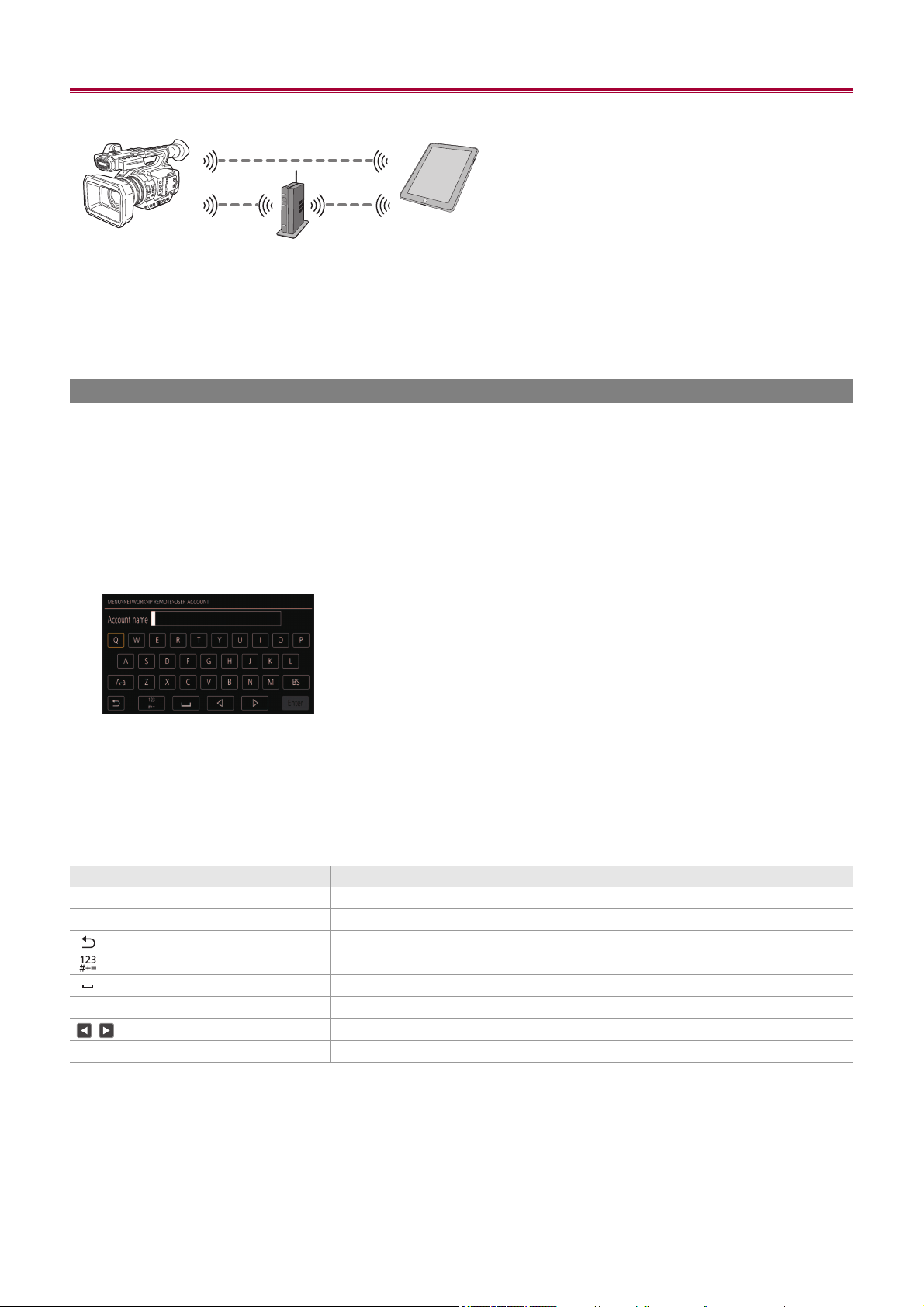
Network Connection – Connecting to the iPhone/iPad or Android terminal
278
Connecting to the iPhone/iPad or Android terminal
The unit can be operated from the iPhone/iPad or Android terminal.
≥Unit settings: 278
≥Preparing the HC ROP app: 279
≥Connecting to the HC ROP app: 279
≥Operation while the HC ROP app is connected: 279
Unit settings
Specifying the network settings
Specify the network settings. (
ÎNetwork settings: 271)
Setting the user account name and the password
Set the user account and password for entry into the HC ROP app.
1
Select the [NETWORK] menu ¨ [IP REMOTE] ¨ [USER ACCOUNT].
2
Enter the user account name and select [Enter].
• Enter the user account name with 31 characters or less.
3
Enter the password and select [Enter].
• Enter a password between 8 characters and 15 characters.
To enter a character
Operation is the same as entering with a keyboard.
Enabling the IP remote function
1
Select the [NETWORK] menu ¨ [IP REMOTE] ¨ [ENABLE/DISABLE] ¨ [ENABLE].
Icon Description of operation
[A-a] Switches between upper case and lower case. (Displayed during the text entry mode)
[@-#] Switches the type of the symbols. (Displayed during the symbol entry mode)
[ ] Returns to the previous screen. Entered character is not reflected.
Switches the character to symbol/number.
Enters space (blank).
[BS] Deletes the character. Previous character is deleted when the cursor position is empty.
/ Moves the cursor to right or left.
[Enter] Completes the character entry.
Network Connection – Connecting to the iPhone/iPad or Android terminal
279
Setting the standby port number
Depending on the environment, set the port number for standby if required.
1
Set the port number in the [NETWORK] menu ¨ [IP REMOTE] ¨ [HC ROP PORT].
Checking/deleting user accounts
1
Select the [NETWORK] menu ¨ [IP REMOTE] ¨ [ACCOUNT LIST].
The list of registered user accounts is displayed.
• Proceed to Step 4 to only check user accounts.
2
Select the user account to be deleted.
3
When the confirmation message is displayed, select [SET].
4
Select [ ] and end the operation.
Preparing the HC ROP app
Install the HC ROP app to the iPhone/iPad or Android terminal.
For iPhone/iPad
• Download the HC ROP app from the App Store.
For Android terminal
• Download the HC ROP app from the Google Play Store.
Connecting to the HC ROP app
Connect to the unit following the HC ROP app guide.
Operation while the HC ROP app is connected
Operation of the unit that is connected
The <THUMBNAIL> button cannot be used.
Recording and playback operation while connected
• Recording can be operated by either the unit or the HC ROP app.
• Playback operation is not possible.
• The setting value is not reflected until the [NETWORK] menu ¨ [IP REMOTE] ¨ [ENABLE/DISABLE] is switched to
[DISABLE] once, or when the camera is restarted.
• Number 80 and the same value as the port number set for other menu item cannot be specified.
• The TCP port set as the setting value and the UDP port set as the setting value +1 will be used.
• Inquire the administrator of the network or the controller whether change is required.
• For information such as the supported OS of the HC ROP app, refer to the App Store or the Google Play Store download
page.
• Change the connection destination port number in HC ROP app if the standby port number is changed in this unit.
• The unit cannot connect with the HC ROP app while the menu or thumbnail screen is displayed.
• For details about operation of the HC ROP app, refer to the help for the HC ROP app.
• The content set with the remote operation using the HC ROP app is reflected to the unit. (Excluding setting by hard switch)

Network Connection – Streaming function
280
Streaming function
You can perform streaming of audio and video currently shot with the unit over a network (wired LAN, wireless LAN, and USB
tethering
*
).
Streaming can be performed using the unit, application software of a device connected via a network, or a server that is capable
of receiving streaming video sent from the unit.
There are 2 ways to start streaming: streaming from application software and streaming from the unit. This section describes
how to connect the unit to a network for each method.
* Available for use when using .
≥Basic setting of the camera: 281
≥Setting for each protocol and starting the streaming: 283
≥Management of setting information: 285
≥Entering the setting using the setting tool: 286
•
Streaming stops when performing operations such as displaying the thumbnail screen or playing back clips on the camera.
• Streaming may stop when the date/time is set while streaming.
• If there is a setting that disables VFR and other streaming functions in the scene file, streaming will end due to the scene file
changing.
• Take caution as streaming image may unintentionally be released depending on the system environment to stream on and
setting of the service and system used.

Network Connection – Streaming function
281
Basic setting of the camera
Specifying the network settings
Specify the network settings. (
ÎNetwork settings: 271)
Settings for the streaming function
1
Set the [SYSTEM] menu ¨ [FREQUENCY]/[REC FORMAT].
Set to the FHD (1920×1080) recording format.
2
Select the [NETWORK] menu ¨ [NETWORK FUNC] ¨ [STREAMING].
Streaming function is enabled.
3
Select the protocol with the [NETWORK] menu ¨ [STREAMING] ¨ [STREAMING
PROTOCOL].
4
In the [NETWORK] menu ¨ [STREAMING] ¨ [STREAMING FORMAT], set the format
when streaming.
• For details about the setting items (
ÎSettings when using the streaming function: 282)
5
Set the setting corresponding to the selected protocol. (ÎSetting for each protocol
and starting the streaming: 283
)
• The streaming function can be used when all of the following conditions are satisfied.
– The [SCENE FILE] menu ¨ [VFR] ¨ [OFF] is set
– The [SYSTEM] menu ¨ [SUPER SLOW] ¨ [OFF] is set
– The menu has been set according to “Settings when using the streaming function” (This cannot be used when set to
UHD) (
ÎSettings when using the streaming function: 282)
– Interval recording, background recording, and dual codec recording
*
are disabled
* Available for setting when using .
(For the )
• When the [SCENE FILE] menu
¨ [GAMMA MODE SEL] is set to [HLG], video is streamed after converting from high
dynamic range to standard dynamic range.
• When the [SCENE FILE] menu
¨ [GAMMA MODE SEL] is set to [V-Log], video is streamed after converting from V-Log to
V-709.

Network Connection – Streaming function
282
Settings when using the streaming function
The item that can be selected varies depending on the [STREAMING PROTOCOL] settings.
• When the [SYSTEM] menu
¨ [FREQUENCY] ¨ [59.94Hz] is set
[SYSTEM] menu [NETWORK] menu ¨ [STREAMING]
[FILE FORMAT] [REC FORMAT] [STREAMING FORMAT]
[MOV] [1080-59.94p/422LongGOP 100M]
[1080-59.94p/422ALL-I 200M]
[1920×1080-60fps 24M]
[1920×1080-60fps 20M]
[1920×1080-60fps 16M]
[1280×720-60fps 14M]
[1280×720-60fps 8M]
[1280×720-60fps 3M]
[640×360-30fps 4M]
[640×360-30fps 1.5M]
[640×360-30fps 0.7M]
*
[320×180-30fps 4M]
[320×180-30fps 1.5M]
[320×180-30fps 0.5M]
[MP4] [1080-59.94p/420LongGOP 50M]
[AVCHD] [1080-59.94p/AVCHD PS]
[MOV] [1080-59.94i/422LongGOP 50M]
[1080-59.94i/422ALL-I 100M]
[1080-29.97p/422LongGOP 50M]
[1080-29.97p/422ALL-I 100M]
[1920×1080-30fps 14M]
[1920×1080-30fps 6M]
[1920×1080-30fps 1M]
[1280×720-30fps 8M]
[1280×720-30fps 2M]
[1280×720-30fps 1M]
[640×360-30fps 4M]
[640×360-30fps 1.5M]
[640×360-30fps 0.7M]
*
[320×180-30fps 4M]
[320×180-30fps 1.5M]
[320×180-30fps 0.5M]
[AVCHD] [1080-59.94i/AVCHD PH]
[1080-59.94i/AVCHD HA]
[MOV] [1080-23.98p/422LongGOP 50M]
[1080-23.98p/422ALL-I 100M]
[1920×1080-24fps 14M]
[1920×1080-24fps 6M]
[1920×1080-24fps 1M]
*
[MP4] [1080-23.98p/420LongGOP 50M]
[AVCHD] [1080-23.98p/AVCHD PH]
[AVCHD] [720-59.94p/AVCHD PM] [1280×720-60fps 14M]
[1280×720-60fps 8M]
[1280×720-60fps 3M]
[640×360-30fps 4M]
[640×360-30fps 1.5M]
[640×360-30fps 0.7M]
*
[320×180-30fps 4M]
[320×180-30fps 1.5M]
[320×180-30fps 0.5M]

Network Connection – Streaming function
283
• When the [SYSTEM] menu ¨ [FREQUENCY] ¨ [50.00Hz] is set
* Factory setting
Setting for each protocol and starting the streaming
RTMP(S)
1
Select the [NETWORK] menu ¨ [STREAMING] ¨ [STREAMING PROTOCOL] ¨
[RTMP(S)].
2
Set the destination. (ÎSetting of the destination: 285)
3
Select the [NETWORK] menu ¨ [STREAMING] ¨ [START] ¨ [ON].
If the camera is connected to the transmission destination through a network, the camera starts the transmission of
streaming video.
• To stop the transmission of the streaming image, select the [NETWORK] menu
¨ [STREAMING] ¨ [START] ¨ [OFF].
[SYSTEM] menu [NETWORK] menu ¨ [STREAMING]
[FILE FORMAT] [REC FORMAT] [STREAMING FORMAT]
[MOV] [1080-50.00p/422LongGOP 100M]
[1080-50.00p/422ALL-I 200M]
[1920×1080-50fps 24M]
[1920×1080-50fps 20M]
[1920×1080-50fps 16M]
[1280×720-50fps 14M]
[1280×720-50fps 8M]
[1280×720-50fps 3M]
[640×360-25fps 4M]
[640×360-25fps 1.5M]
[640×360-25fps 0.7M]
*
[320×180-25fps 4M]
[320×180-25fps 1.5M]
[320×180-25fps 0.5M]
[MP4] [1080-50.00p/420LongGOP 50M]
[AVCHD] [1080-50.00p/AVCHD PS]
[MOV] [1080-50.00i/422LongGOP 50M]
[1080-50.00i/422ALL-I 100M]
[1080-25.00p/422LongGOP 50M]
[1080-25.00p/422ALL-I 100M]
[1920×1080-25fps 14M]
[1920×1080-25fps 6M]
[1920×1080-25fps 1M]
[1280×720-25fps 8M]
[1280×720-25fps 2M]
[1280×720-25fps 1M]
[640×360-25fps 4M]
[640×360-25fps 1.5M]
[640×360-25fps 0.7M]
*
[320×180-25fps 4M]
[320×180-25fps 1.5M]
[320×180-25fps 0.5M]
[AVCHD] [1080-50.00i/AVCHD PH]
[1080-50.00i/AVCHD HA]
[AVCHD] [720-50.00p/AVCHD PM] [1280×720-50fps 14M]
[1280×720-50fps 8M]
[1280×720-50fps 3M]
[640×360-25fps 4M]
[640×360-25fps 1.5M]
[640×360-25fps 0.7M]
*
[320×180-25fps 4M]
[320×180-25fps 1.5M]
[320×180-25fps 0.5M]
• [START] menu cannot be selected when the streaming cannot be started due to reasons such as the network is not
connected, etc.
• Starting/stopping of the streaming from the camera can be assigned to the USER button. (
ÎAssigning functions to the
USER buttons: 65
)
• Streaming cannot be started by pressing the USER button or touching the USER button icon when the menu or the
thumbnail screen is displayed.
• IPv6 cannot be used for RTMP(S).
• For settings such as URL, refer to the manual for each streaming service.
• Streaming may not be possible depending on the operating condition of the streaming service.

Network Connection – Streaming function
284
RTSP
Start the streaming with an operation of the application software or device at the receiving side (referred to as “receiving side”
hereinafter).
1
Select the [NETWORK] menu ¨ [STREAMING] ¨ [STREAMING PROTOCOL] ¨
[RTSP].
2
Set the standby port with the [NETWORK] menu ¨ [STREAMING] ¨ [RTSP SETTING]
¨ [LISTEN PORT] on the camera if required.
3
Specify the IP address and the path of the camera as following on the receiving side,
and start streaming.
rtsp://(IP address):(Port number)/stream
Streaming with multicast
One streaming can be distributed to multiple receivers via supported router, etc., when the multicast function is used.
1
Select the [NETWORK] menu ¨ [STREAMING] ¨ [RTSP SETTING] ¨ [MULTICAST] ¨
[ENABLE].
2
Select the [NETWORK] menu ¨ [STREAMING] ¨ [RTSP SETTING], and specify
[MULTICAST ADDRESS] and [MULTICAST PORT].
• Set [MULTICAST ADDRESS] within following range.
– IPv4: 224.0.1.0 to 239.255.255.254
– IPv6: Multicast address starting with FF
• Set [MULTICAST PORT] within the range of 1024 to 50000.
3
Specify the address of the unit and start streaming with the application software.
• Stop the streaming with the operation in the receiving side.
• For details about the operations to start streaming from the application software, please see the manual for the application
software.
• Streaming cannot be started while the thumbnail screen is displayed.
• Depending on the specification of the device receiving streaming and the connected router, quality of the video image may
not be preserved. When streaming by multicast, contact the administrator of the network being used and prepare
appropriate communication environment.
• Disable the LAN card not to be used when receiving the multicast image to be displayed on a computer with multiple LAN
cards installed.
• Range of streaming can be adjusted with the [NETWORK] menu
¨ [STREAMING] ¨ [RTSP SETTING] ¨ [TTL/HOP
LIMIT]. For details, contact the network administrator.

Network Connection – Streaming function
285
Management of setting information
You can set, save and load the RTMP(S) destination.
Setting of the destination
Information regarding the destination can be set or referenced.
Setting the destination with the camera menu
1
Select the [NETWORK] menu ¨ [STREAMING] ¨ [CONNECTION INFO.] ¨ [MEMORY].
2
Enter the destination URL in the [NETWORK] menu ¨ [STREAMING] ¨ [RTMP(S)
RECEIVER URL].
• Enter the destination URL in following format.
– rtmp://(server URL):(port number)/(path)/(stream key)
– rtmps://(server URL):(port number)/(path)/(stream key)
Referencing destination from the memory card
1
Insert the memory card with the destination information saved.
• The card slot to perform loading and saving can be set in the [OTHERS] menu
¨ [FILE] ¨ [SLOT FOR LOAD/SAVE].
2
Select the [NETWORK] menu ¨ [STREAMING] ¨ [CONNECTION INFO.] ¨ [SD CARD].
Saving the destination information on the memory card
1
Insert a memory card formatted with the unit.
• The card slot to perform loading and saving can be set in the [OTHERS] menu
¨ [FILE] ¨ [SLOT FOR LOAD/SAVE].
2
Select the [NETWORK] menu ¨ [STREAMING] ¨ [SAVE (SD CARD)].
3
Select [YES].
Loading destination information from the memory card
1
Insert the memory card with the destination information saved.
• The card slot to perform loading and saving can be set in the [OTHERS] menu
¨ [FILE] ¨ [SLOT FOR LOAD/SAVE].
2
Select the [NETWORK] menu ¨ [STREAMING] ¨ [LOAD (SD CARD)].
3
Select [YES].
• In general, a parameter for the stream key is required for URL, but the stream key may be contained as a part of the path
depending on the service. For details, refer to the manual for each streaming service.
• If the setting information in the memory card is not information for the selected protocol or the cloud, it will be treated as no
setting.
• Only items saved are the ones that are used in the destination setting.
• The name of the file in the memory card to save the destination information cannot be changed.
• The file with the destination information saved on the memory card is encrypted.
• Save is not possible when the starting character string of the [RTMP(S) RECEIVER URL] (“rtmp://”, etc.) is not set correctly.
• The name of the file to load destination information saved on the memory card cannot be selected.
• The setting information that can be loaded (referenced) by the unit is as follows.
– Information saved with the unit
– Setting file created with the P2 Network Setting software (
ÎEntering the setting using the setting tool: 286)
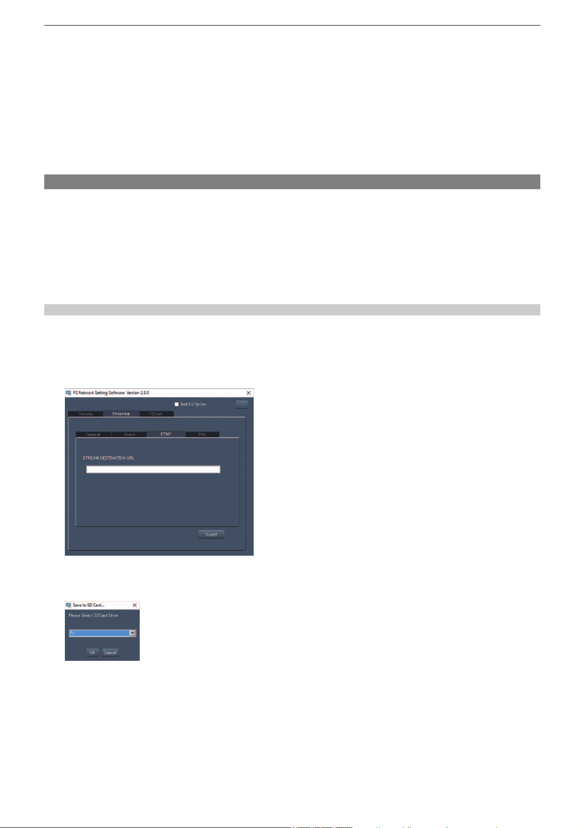
Network Connection – Streaming function
286
Clearing the destination information
1
Select the [NETWORK] menu ¨ [STREAMING] ¨ [CLEAR (MEMORY)].
Stopping streaming of video
Stop the streaming in following procedure if the streaming was started with the operation of the camera.
1
Select the [NETWORK] menu ¨ [STREAMING] ¨ [START] ¨ [OFF].
• If [STREAMING START] is assigned to a USER button, streaming can also be stopped with the USER button.
(
ÎAssigning functions to the USER buttons: 65)
Entering the setting using the setting tool
Installing software
Download and expand the P2 Network Setting software for Windows from the following website.
https://panasonic.jp/support/global/cs/e_cam/index.html
Creating the SD card for setting using the P2 Network Setting software
The SD card created with this software can be used as the reference destination when loading into the unit’s menu or when the
[NETWORK] menu ¨ [STREAMING] ¨ [CONNECTION INFO.] ¨ [SD CARD] is selected.
Setting procedure
1
Start the P2 Network Setting software.
2
Select the “Streaming” tab ¨ “RTMP” tab.
3
Enter the destination URL in “STREAM DESTINATION URL”.
4
Click “Export” and select the destination in the drive selection dialog, and then click
“OK”.
• This cannot be saved to anything other than a removable drive.


Notes – Frequently asked questions
288
Frequently asked questions
≥Power supply/Battery: 288
≥Memory card: 289
≥Indication: 289
≥Shooting: 289
≥Playback: 290
≥Connections with external devices: 290
≥Computers: 290
≥Others: 291
It is not a malfunction in following cases
Power supply/Battery
What is the power supply voltage supported by the supplied AC adaptor?
• AC 100 V-240 V
Can the supplied AC adaptor be used while the battery is attached?
• It can be used. The power supply automatically switches to the AC adaptor when you connect an AC adaptor.
The power status display in the LCD monitor will change from the mark to the mark.
This unit cannot be turned on. This unit does not stay on long enough. Battery runs
down quickly.
• Charge the battery again to ensure it is sufficiently charged. (ÎCharging the battery: 31)
• In cold places, the battery using time becomes shorter.
• The battery has a limited life. If the operating time is still too short even after the battery is fully charged, the battery has worn
out and needs to be replaced.
This unit cannot be operated though it is turned on.
• Remove the power supply (the battery or the AC adaptor), and connect it again after approximately 1 minute. (Conducting the
above operation while the memory card is being accessed may damage the data on the media.)
• If normal operation is still not restored, detach the power connected, and consult the dealer who you purchased this unit from.
[PLEASE TURN UNIT OFF, THEN TURN ON AGAIN.] is displayed.
• The unit has automatically detected an error. Restart the unit by turning off and on.
• The unit will be turned off in about 1 minute if the unit is not turned off and on.
• Repair is needed if it is repeatedly displayed even if it is restarted. Detach the power connected, and consult the dealer who
you purchased this unit from. Do not attempt to repair the unit by yourself.
Can the battery that was used in the previous models used?
• It is recommended to use the following Panasonic genuine batteries.
– AG-VBR59 (supplied/optional, 7.28 V, 5900 mAh)
– AG-VBR89 (optional, 7.28 V, 8850 mAh)
– AG-VBR118 (optional, 7.28 V, 11800 mAh)
The lens, the viewfinder or LCD monitor fog
up.
This is due to condensation. This is not a malfunction. (
ÎAbout Condensation (When the
lens, the viewfinder or LCD Monitor is fogged up): 12
)
The unit clatters when tilted forward/
backward.
Due to the construction of the unit section, some parts make a clattering sound when the
power is turned off. This is not a malfunction.
A short click sound occurs when the power
is turned on.
This is an initial operation of the startup of the lens of the camera. This is due to the camera
mechanism and is not a malfunction.
Object seems to be warped.
Object seems to be warped slightly when the object moves across the image very fast, but
this is because the unit is using MOS for the image sensor. This is not a malfunction.

Notes – Frequently asked questions
289
Memory card
If the SD card is inserted in this unit, it is not recognized.
• The memory card to use with the unit should always be formatted on the unit.
The memory card formatted on a computer cannot be used in the unit.
Indication
Function display (Remaining Display, Counter Display, etc.) is not displayed.
• Press the <DISP/MODE CHK> button.
• Check the menu settings in the [VIDEO OUT/LCD/VF] menu
¨ [INDICATOR].
• Press the <COUNTER> button to switch the counter display.
Shooting
The focus is not adjusted automatically.
• Is the manual focus mode set? Set the auto focus mode to adjust the focus automatically.
• Are you shooting in conditions which focusing is difficult with the auto focus mode? Auto focus has trouble focusing under
certain conditions. In this case, the manual focus mode can be used to focus the unit.
Under following conditions, focus may not be adjusted properly:
– Shooting subjects that is in long and short distances at the same time
– Shooting a subject through a dirty glass
– Shooting in a dark place
– With a glittering object nearby
– Shooting a fast-moving subject
– Shooting a low contrast subject
The unit arbitrarily stops recording.
• When the recording format is set to MOV format/MP4 format, use SDXC memory cards. MOV format/MP4 format data cannot
be recorded to SDHC memory cards.
• Use the memory card with the required Speed Class in accordance with the recording bit rate. (
ÎSpeed Class during
shooting: 45
)
Audio cannot be recorded.
• Audio cannot be recorded in the following cases. ( is displayed in the camera image screen.)
– When the variable frame rate recording function is enabled and the frame rate set is different from the frame rate of the
recording format
– When the super slow recording function is enabled
– When the interval recording function is enabled
Color or brightness of the image changes, or you may see horizontal bars in the
image. The LCD monitor flickers indoors.
• Color or brightness of the image may change, or you may see horizontal bars in the image when the object is recorded under
fluorescent light, mercury light or sodium light, etc., but this is not a malfunction.
• Adjust using the following methods:
– Switch to auto shutter mode
– Adjust the shutter speed to 1/50, 1/60, or 1/100
– Adjusting with the synchro scan shutter speed

Notes – Frequently asked questions
290
Playback
The clip cannot be played back.
• The clip displaying in the thumbnail screen cannot be played back.
is displayed on following clips.
– A clip shot with other device, a clip edited by an editing software
– Corrupted clip
• is displayed on the clip in the thumbnail screen for the clips with different system frequency. Change the system
frequency.
• The clip with different recording file format (MOV/MP4/AVCHD) is not displayed in the thumbnail screen. Change the recording
file format.
The clip cannot be deleted.
• Cancel the protect on the clip.
• It may not be possible to delete clips that have displayed on them in the thumbnail screen.
Format the memory card if the clip is unnecessary.
All data recorded on the memory card will be deleted when it is formatted. Save the necessary data into a computer, etc.
Hot swap playback cannot be performed.
• This unit does not support hot swap playback.
Connections with external devices
A TV/external monitor is properly connected, but images do not appear. Images are
stretched vertically.
• Read the operating instructions for the TV/external monitor, and switch the input to suit the terminal connected.
• Depending on the cable you have used to connect the TV/external monitor, change the settings on this unit. (
Î[VIDEO OUT
SEL]: 97
, [OUT FORMAT]: 99)
Images and audio not being output even when the TV/external monitor is connected to
this unit with an HDMI cable.
• Check if the HDMI cable is connected correctly.
• Insert the HDMI cable all the way in.
If the memory card is inserted in another device, it is not recognized.
• Check that the device is compatible with the capacity or type of memory card (SDHC Memory Card/SDXC Memory Card) that
you inserted. Refer to the operating instructions of the device for details.
When connected by the USB cable, this unit is not detected by the other devices.
• When connected to other devices using the battery, reconnect using the AC adaptor.
Computers
When connected by the USB cable, this unit is not detected by the computer.
• After re-inserting the memory card into the unit, reconnect the USB cable.
• Select another USB terminal on the computer.
• Check the operating environment. (
ÎOperating environment (mass storage): 265)
• Connect the USB cable again after restarting the computer and turning on this unit again.
When the USB cable is disconnected, an error message will appear on the computer.
• To disconnect the USB cable safely, double-click the icon in the task tray and follow the instructions on the screen.

Notes – Frequently asked questions
291
Others
Which lens filters can be attached?
• 67 mm diameter filters can be attached.
If AVCHD scenes do not change smoothly when played back on another device
In the following cases, when multiple clips are played back in succession, images may pause for a few seconds when changing
between clips.
• The smoothness of playback of successive clips depends on the device used for playback. Depending on the device used for
playback, images may pause for a moment even when the following conditions do not apply.
• When clips recorded successively that exceed 4 GB are played back on other devices, the images may pause for a moment
every 4 GB.
Principal reasons for not playing back
smoothly
• When recordings are made with recording format [PS] and then switched to another recording
format for recording
• When recordings are made on different dates
• When clips less than 3 seconds are recorded
• When recordings are made with pre-recording
• When recordings are made with interval recording
• When clips are deleted
• When there are more than 99 recordings in 1 playlist

Notes – Warning system
292
Warning system
When an error is detected right after the unit is turned on or during the operation, the occurrence of the error is notified in the
camera image screen of the LCD monitor or by the tally lamps. Deal with the error by following the indications.
Cases indicated by error messages
*1 Displayed when using .
*2 Displayed when using .
System error
Warning
Screen display
Description Behavior and cause
Camera image screen
[SYSTEM ERROR] An error in the standard signal or
communication error has occurred.
All of the tally lamps and the card access lamps (orange)
flash 4 times each second, and an alarm sounds.
• Set the power switch to <OFF> and turn off the power.
Screen display
Description Behavior and cause
Camera image screen
[LOW BATTERY] Remaining battery level is insufficient. All of the tally lamps and the card access lamps (orange)
flash 4 times each second, and an alarm sounds.
The power status display becomes , and it will flash once
every second in red.
• The power is turned off in approximately 5 seconds.
• Replace with a fully charged battery, or connect the AC
adaptor.
[HIGH TEMPERATURE] Displayed when the internal
temperature of the main unit has risen
above assumed.
All of the tally lamps and the card access lamps (orange)
flash 4 times each second, and an alarm sounds.
• The power is turned off in approximately 5 seconds.
• Turn on the power again and check recording and playback
operations. If the problem persists, consult the dealer.
[FAN STOPPED] The fan has stopped.
• Recording is stopped.
• The power turns off approximately 1 minute later.
• Stop the use immediately when the fan has stopped, and
consult the dealer.
• If the fan has stopped, temperature of the unit will rise.
Therefore, do not use the unit for a long period of time.
[REC WARNING] An error of the recording data has
occurred during recording, and the
recording has stopped.
All of the tally lamps and the card access lamps (orange)
flash 4 times each second, and an alarm sounds.
• Recording is stopped.
It has tried to record exceeding the
maximum number of clips during
recording.
All of the tally lamps and the card access lamps (orange)
flash 4 times each second, and an alarm sounds.
• Recording is stopped.
• [REC WARNING] [<OVER MAX NUM. OF CLIPS>] is
displayed in the warning display field of the STATUS
screen for the mode check.
• Replace the memory card or delete unnecessary clips.
[Below functions are temporarily
disabled due to a rise of the camera’s
internal temperature. Please wait for
the camera to cool down.
- VIDEO RECORDING
- PRE REC
- USB TETHERING]
*1
Displayed when the internal
temperature of the main unit has risen
above assumed.
All of the tally lamps and the card access lamps (orange)
flash 4 times each second, and an alarm sounds.
• Recording stops if it was in progress.
• Streaming stops if streaming via USB tethering was in
progress.
• [RECORDING] menu
¨ [PRE REC] is fixed to [OFF]
• Wait until the temperature of the unit decreases.
[Below functions are temporarily
disabled due to a rise of the camera’s
internal temperature. Please wait for
the camera to cool down.
- VIDEO RECORDING
- PRE REC
- USB-LAN]
*2
Displayed when the internal
temperature of the main unit has risen
above assumed.
All of the tally lamps and the card access lamps (orange)
flash 4 times each second, and an alarm sounds.
• Recording stops if it was in progress.
• Streaming stops if streaming via a USB ethernet adaptor
was in progress.
• [RECORDING] menu
¨ [PRE REC] is fixed to [OFF]
• Wait until the temperature of the unit decreases.

Notes – Warning system
293
[CARD ERROR <SLOT 1>]/
[CARD ERROR <SLOT 2>]
A data error caused by the memory
card has occurred during recording or
playback.
(When it was recording)
• All of the tally lamps and the card access lamps (orange)
flash 4 times each second, and an alarm sounds.
• Recording is stopped.
• The memory card where the error has occurred is write
protected after recording stops. Replace the memory card
in the card slot where the error has occurred.
(When it was playing back)
• Playback is stopped.
[END]
(Memory card status display)
The remaining recording capacity of
the memory card has exhausted
during recording.
All of the tally lamps and the card access lamps (orange)
flash 4 times each second, and an alarm sounds.
• Recording is stopped.
• Replace the memory card or delete unnecessary clips.
(Once every second, flash in red)
Battery is almost consumed. All of the tally lamps flash once every second.
• The current operation will continue.
• Replace with a fully charged battery, or connect the AC
adaptor.
Remaining recording capacity display
of the memory card
(Flashes once every second during
recording)
The remaining recording capacity of
the memory card is getting low.
• Recording will continue.
• Replace the memory card as necessary.

Notes – Warning system
294
Alert
Screen display
Description Behavior and cause
Camera image screen
[SIMUL REC WARNING <SLOT 1>]/
[SIMUL REC WARNING <SLOT 2>]
An error has occurred in one of the
memory cards during simultaneous
recording.
• Recording to the other memory card will continue.
Recording has been attempted while
the number of clips has exceeded the
limit on one of the memory cards
during simultaneous recording.
• Recording to the other memory card will continue.
• [SIMUL REC WARNING <SLOT 1>] [<OVER MAX NUM.
OF CLIPS>]/[SIMUL REC WARNING <SLOT 2>] [<OVER
MAX NUM. OF CLIPS>] is displayed in the warning display
field of the STATUS screen for the mode check.
• Replace the memory card or delete unnecessary clips.
[BACKGROUND REC WARNING
<SLOT 1>]/
[BACKGROUND REC WARNING
<SLOT 2>]
An error has occurred in one of the
memory cards during background
recording.
• Recording to the other memory card will continue.
Recording has been attempted while
the number of clips has exceeded the
limit on one of the memory cards
during background recording.
• Recording to the other memory card will continue.
• [BACKGROUND REC WARNING <SLOT 1>] [<OVER
MAX NUM. OF CLIPS>]/[BACKGROUND REC WARNING
<SLOT 2>] [<OVER MAX NUM. OF CLIPS>] is displayed
in the warning display field of the STATUS screen for the
mode check.
• Replace the memory card or delete unnecessary clips.
[DUAL CODEC REC WARNING
<SLOT 2>]
*1
An error occurred with the memory
card on the sub recording side during
dual codec recording.
• Recording continues on the memory card on the main
recording side.
During dual codec recording, you are
trying to record when the number of
clips for the memory card on the sub
recording side exceeds the upper
limit.
• Recording continues on the memory card on the main
recording side.
• [DUAL CODEC REC WARNING <SLOT 2>] [<OVER MAX
NUM. OF CLIPS>] is displayed in the warning display field
of the STATUS screen for the mode check.
• Replace the memory card or delete unnecessary clips.
[REINSERT OR CHECK CARD
<SLOT 1>]/
[REINSERT OR CHECK CARD
<SLOT 2>]
The memory card cannot be
recognized properly because a
recording medium which is not
supported has been inserted or there
is dirt on the terminal of the memory
card.
• Check the memory card that is inserted.
• Insert the memory card again if displayed when inserting a
memory card.
[FORMAT ERROR CARD <SLOT 1>]/
[FORMAT ERROR CARD <SLOT 2>]
A memory card with management
information out of specifications has
been inserted.
(Include when the system frequency
(59.94 Hz system or 50.00 Hz system)
for the AVCHD format of the memory
card is different from the setting in the
[SYSTEM] menu
¨ [FREQUENCY])
• Insert a memory card that can record.
• The system frequency information for the AVCHD format is
confirmed at the time of formatting or at the first recording.
[NOT SDXC CARD <SLOT 1>]/
[NOT SDXC CARD <SLOT 2>]
When [FILE FORMAT] is set to MOV
format/MP4 format, there is a memory
card inserted to which MOV format/
MP4 format data cannot be recorded.
• Insert a SDXC memory card.
[INCOMPATIBLE CARD <SLOT 1>]/
[INCOMPATIBLE CARD <SLOT 2>]
A memory card that may not be able
to record due to slow writing speed
has been inserted.
• The current operation will continue.
• Use a memory card with sufficient writing speed.
[BACKUP BATT EMPTY] Voltage lowering of the backup battery
for internal clock was detected when
turning on the power.
• The current operation will continue.
• Set the date/time again after charging the built-in battery.

Notes – Warning system
295
Message
Screen display
Description Behavior and cause
Camera image screen
[FUNCTIONS THAT HAVE BEEN
STOPPED CAN NOW BE USED.]
Functions that were stopped due to a
temperature increase in the unit have
been released for use again.
—
[CANNOT PLAY.] This is a clip that cannot be played
back.
(When it cannot be played back due to
difference of the system frequency,
etc.)
An error has occurred during
playback, and the playback has
stopped.
• Confirm if the system frequency of the clip is the same as
the system frequency of the unit.
• Check the clip.
[CANNOT DELETE.] This is a clip that cannot be deleted.
• Match the device and content versions.
[CANNOT RECORD. THE NUMBER
OF CLIPS HAS EXCEEDED THE
MAXIMUM LIMIT.]
The number of clips that can be
recorded has reached the maximum.
• Replace the memory card or delete unnecessary clips.
[CARD ERROR. PLEASE
REFORMAT.]
Formatting of the memory card has
failed.
• Format it again.
[CANNOT COPY TO SAME CARD.] The clip recorded over multiple
memory cards cannot be copied to a
same card.
• Copy to a card not containing a clip that is recorded over
multiple memory cards.
[Repair failed.] Repairing the clip where an error
occurred has failed because the
power was disconnected or the
memory card was removed during
recording.
Restoring of the management
information has failed.
• Check the memory card.
[UNABLE TO FORMAT.] This memory card cannot be
formatted.
• Check the memory card.
[CANNOT PROTECT.] This is a clip that cannot be protected. • Match the device and content versions.
[THE CLIP IS PROTECTED. PLEASE
CANCEL PROTECTION.]
The clip is protected so it cannot be
deleted.
• Cancel the protect on the clip.
[THUMBNAIL DATA ERROR IS
DETECTED.]
An error occurred in the thumbnail
information of the memory card.
• Restoring of the management information is performed
automatically after this.
[CANNOT RECORD -
INCOMPATIBLE CONTROL DATA.]
The version of the management
information on the memory card is not
supported.
• Match the device and content versions.
[CANNOT SET.] This cannot be set.
• Perform the setting after making it possible to set.
[THIS CLIP CANNOT BE COPIED.] The clip cannot be copied.
• Copy the clips other than the corresponding clip.
[CONTROL DATA ERROR HAS
BEEN DETECTED. (SD CARD)]
An error occurred in the management
information of the memory card.
• Restoring of the management information is performed
automatically after this.
[COPY FAILED. PLEASE CHECK
THE CARD.]
The clip has failed to copy due to an
error in the memory card.
• Check the memory card.
[CANNOT COPY - THE NUMBER OF
CLIPS HAS REACHED MAXIMUM.]
The number of clips that can be
copied has reached the maximum.
• Replace the memory card in the copy destination or delete
unnecessary clips.
[LOW BATTERY. PLEASE CONNECT
AC ADAPTOR OR CHANGE
BATTERY.]
It is trying to copy a clip or update the
firmware of the unit when the
remaining battery level is insufficient.
• Replace with a fully charged battery, or connect the AC
adaptor.
[CANNOT PLAY THIS CLIP ON THIS
MODEL.]
This is a clip that cannot be played
back with the unit.
• Playback on a device that can playback.
[Cannot copy: contains recordings
from other devices.]
The clip recorded in other device
cannot be copied.
• Copy the clips other than the corresponding clip.
[INVALID] Operation is disabled.
• Operate after the operation becomes enabled.
[Cannot record - Playlist capacity is
full.]
The unit tried to record on a memory
card where the number of playlists for
recording has reached the maximum.
• Replace the memory card or delete unnecessary clips.
[Cannot copy - Playlist capacity is full.] The unit tried to copy to a memory
card where the number of playlists for
recording has reached the maximum.
• Replace the memory card or delete unnecessary clips.
[Exceeds capacity. Please reselect.] The remaining recording capacity of
the memory card for the copy
destination is insufficient.
• Select the clip to copy again, or secure enough space in
the remaining recording capacity on the memory card for
the copy destination.

Notes – Warning system
296
[Check the destination media.] An error has occurred on the memory
card for the copy destination while
copying.
• Confirm the memory card for the copy destination.
[LOAD NG] Loading of the scene file has failed.
• Check the memory card.
[SAVE NG] Writing of the scene file has failed.
• Check the memory card.
[DISCONNECT USB CABLE.] Due to an OS non-compatible error,
5 minutes has elapsed until the
service mode connection is
established.
• Confirm if the OS in use is supported by the unit.
[CARD LOCKED.] The unit tried to protect or delete a clip
on a memory card that has been
locked.
The unit tried to copy a clip to the
memory card that has been locked.
• Unlock the memory card.
[CANNOT SELECT MORE CLIPS.] It has tried to select more than 99
clips.
• Execute the process such as copying by every 99 clips.
[SELECT THE CLIP TO BE
DELETED.]
It has tried to delete a clip without
choosing any.
• Select a clip to be deleted.
[SELECT THE CLIPS TO COPY.] It has tried to copy a clip without
choosing any.
• Select a clip to be copied.
[Insert a card in slot 1.] Copying was tried to be executed
without inserting a memory card into
card slot 1.
• Insert a memory card into card slot 1.
[Insert a card in slot 2.] Copying was tried to be executed
without inserting a memory card into
card slot 2.
• Insert a memory card into card slot 2.
[REINSERT OR CHECK CARD
<SLOT 1>]/
[REINSERT OR CHECK CARD
<SLOT 2>]
It has tried to copy to an error card.
• Check the memory card.
[CANNOT COPY.] Copying was attempted while the
system frequency (59.94 Hz and
50.00 Hz) of the memory card to copy
from and the memory card to copy to
are different for content recorded in
AVCHD format.
• Set the same system frequency (59.94 Hz system or
50.00 Hz system) for the content of the memory card to
copy from and the memory card to copy to.
• The system frequency information for the AVCHD format is
confirmed at the time of formatting or at the first recording.
[CANNOT RECORD.] Cannot be recorded.
• Perform recording after making it possible.
[REC PAUSE INVALID] The unit tried to stop the next
recording before the previous
recording finished writing to the
memory card.
• Stop recording after writing to the memory card is
complete. Recording can be stopped after the message
that is displayed disappears.
[WRITE PROTECTED] The memory card has been
write-protected.
• Insert a memory card with write access.

Notes – Recording function that cannot be used simultaneously
297
Recording function that cannot be used simultaneously
Depending on the recording function that is set, there are recording functions that cannot be used simultaneously.
• Meaning of the symbols used in the table are as follows.
3: Can be used simultaneously.
—: Cannot be used simultaneously.
* Available for use when using .
Recording function to
additionally set
Recording function that is set
Pre-recording Relay recording Simultaneous recording Background recording
Pre-recording
33—
Relay recording 3
——
Simultaneous recording 3 —
—
Background recording — — —
Dual codec recording
*
3 ———
Interval recording — — 3 —
Variable frame rate
recording
————
Super slow recording — — — —
Recording function to
additionally set
Recording function that is set
Dual codec recording
*
Interval recording
Variable frame rate
recording
Super slow recording
Pre-recording 3 ———
Relay recording — — — —
Simultaneous recording — 3 ——
Background recording — — — —
Dual codec recording
*
———
Interval recording —
——
Variable frame rate
recording
——
—
Super slow recording — — —

Notes – Updating the unit’s firmware
298
Updating the unit’s firmware
After confirming the firmware version of the unit with [OTHERS] menu
¨ [INFORMATION] ¨ [VERSION], access the
latest information regarding the firmware on the website shown below, then download the firmware if necessary.
• Update is completed by loading the downloaded file to the unit via the memory card. Insert the memory card that stores the
update file into card slot 1, and select the [OTHERS] menu
¨ [INFORMATION] ¨ [UPDATE].
For the latest update information, check the support website below. (As of August 2022)
https://panasonic.jp/support/global/cs/e_cam
(This website is in English only.)
• When updating the firmware, use the AC adaptor or sufficiently charged battery.
• Do not turn off the power while updating the firmware. Rewriting of the firmware may fail and the unit may not be activated.

Notes – Cleaning and storing
299
Cleaning and storing
Cleaning the main unit
• Remove the battery or disconnect the AC cable from the power outlet before cleaning.
• Do not use benzine or thinner to clean the unit. Using benzine or thinner may cause deformation or peeling off of the paint of
the main unit.
• Wipe the main unit with a soft and clean cloth. For heavy dirt, wipe with a cloth soaked in kitchen detergent diluted with water,
and then with a dry cloth.
• When using a chemical dust cloth, follow the instructions that came with the cloth.
Cautions for storage
Remove the battery from the main unit when storing. Store them in a place where humidity is low and temperature is relatively
constant.
When storing the unit, it is recommended that you place a desiccant (silica gel) in with it.
• Recommended temperature: 15 °C to 25 °C (59 °F to 77 °F)
• Recommended relative humidity: 40 % to 60 %
Main unit
•
Wrap in a soft cloth to prevent dust from getting inside.
Battery
•
The battery life shortens where the temperature is extremely high or low.
• Storing in a place where there is heavy oil smoke or dust may lead to malfunctions due to rust on terminal connectors, etc.
• Do not let the battery terminal contact a metal object (such as a necklace or hairpin). Short circuit may occur between
terminals and it may lead to heat generation. Touching on a heated part may cause severe burns.
• Store the battery with electrically discharged. For long-term storage, it is recommended to charge the battery at least once a
year and use it up completely on the unit before storing it again.
• Remove dust and other debris that gather on the contacts of the battery.
Memory card
•
Do not allow dirt, water, or other foreign objects to get into the contacts on the back of the card.
• If you remove it from the unit, be sure to put it in its case.
• Do not place SD cards in the following areas:
– Where corrosive gases, etc., may be generated
– In places exposed to direct sunlight, or places with high temperatures such as near heating devices
– Where there is excessive moisture or dust
– Locations susceptible to significant difference in temperature (condensation can occur.)
– Where static electricity or electromagnetic waves occur

Notes – Trademark
300
Trademark
• SDXC logo is a trademark of SD-3C, LLC.
• “AVCHD”, “AVCHD Progressive” and the “AVCHD Progressive” logo are trademarks of Panasonic Holdings Corporation and
Sony Corporation.
• Manufactured under license from Dolby Laboratories. Dolby, Dolby Audio, and the double-D symbol are trademarks of Dolby
Laboratories Licensing Corporation.
• The terms HDMI and HDMI High-Definition Multimedia Interface, and the HDMI Logo are trademarks or registered trademarks
of HDMI Licensing Administrator, Inc. in the United States and other countries.
• USB Type-C
®
and USB-C
®
are registered trademarks of USB Implementers Forum.
• Windows
®
is a registered trademark or trademark of Microsoft Corporation in the United States and/or other countries.
• Screenshots are used according to Microsoft Corporation guidelines.
• Intel
®
and Intel
®
Core
™
are trademarks of Intel Corporation in the U.S. and/or other countries.
• Mac and macOS are trademarks of Apple Inc. registered in the U.S. and other countries.
• iPhone and iPad are trademarks of Apple Inc. registered in the U.S. and other countries.
• App Store is a service mark of Apple Inc.
• Google, Android and Google Play are trademarks of Google LLC.
• The Wi-Fi CERTIFIED
™
Logo is a registered trademark of Wi-Fi Alliance
®
.
• The Wi-Fi Protected Setup
™
Logo is a registered trademark of Wi-Fi Alliance
®
.
• “Wi-Fi
®
” is a registered trademark of Wi-Fi Alliance
®
.
• “Wi-Fi Protected Setup
™
”, “WPA
™
”, and “WPA2
™
” are trademarks of Wi-Fi Alliance
®
.
• All other names, company names, product names, etc., contained in this instruction manual are trademarks or registered
trademarks of their respective owners.

Notes – Trademark
301
License
This product is licensed under the AVC Patent Portfolio License for the personal use of a consumer or other uses in which it
does not receive remuneration to (i) encode video in compliance with the AVC Standard (“AVC Video”) and/or (ii) decode AVC
Video that was encoded by a consumer engaged in a personal activity and/or was obtained from a video provider licensed to
provide AVC Video. No license is granted or shall be implied for any other use. Additional information may be obtained from
MPEG LA, L.L.C.
See http://www.mpegla.com
• Separate license contract with MPEG-LA is required to record in a memory card with this product and to distribute that card to
end users for a profit. The end user mentioned here indicates a person or organization that handles contents for a personal
use.
Software information about this product
This product incorporates the following software:
(1) the software developed independently by or for Panasonic,
(2) the software owned by third party and licensed to Panasonic,
(3) the software licensed under the GNU General Public License, Version 2.0 (GPL V2.0),
(4) the software licensed under the GNU LESSER General Public License, Version 2.1 (LGPL V2.1), and/or
(5) open source software other than the software licensed under the GPL V2.0 and/or LGPL V2.1.
The software categorized as (3) - (5) are distributed in the hope that it will be useful, but WITHOUT ANY WARRANTY, without
even the implied warranty of MERCHANTABILITY or FITNESS FOR A PARTICULAR PURPOSE.
For details, refer to the terms of license that are displayed using the following method:
1. Select the [NETWORK] menu
¨ [DEVICE SEL] ¨ [LAN]
*
, [WLAN] or [OFF].
2. Select the [OTHERS] menu
¨ [USB DEVICE] ¨ [SERVICE MODE] ¨ [YES].
Select “LICENSE.TXT” in the external drive recognized by the computer.
* Available for setting when using .
At least three (3) years from delivery of this product, Panasonic will give to any third party who contacts us at the contact
information provided below, for a charge no more than our cost of physically performing source code distribution, a complete
machine-readable copy of the corresponding source code covered under GPL V2.0 or LGPL V2.1, as well as the respective
copyright notice thereof.
Contact Information: oss-cd-reques[email protected]anasonic.com
The source code and the copyright notice are also available for free in our website below.
https://panasonic.net/cns/oss/index.html

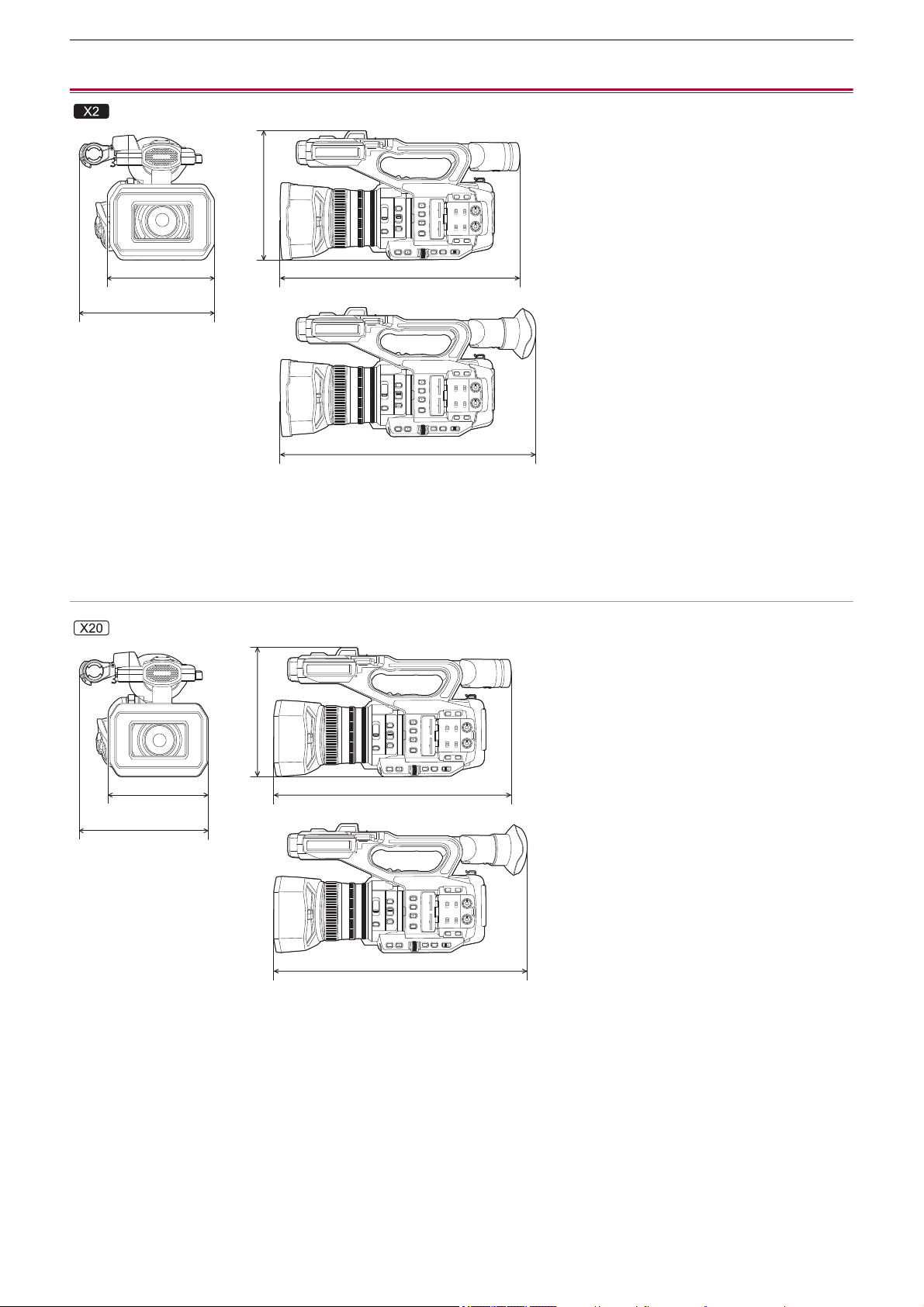
Specification – Dimensions
303
Dimensions
(A) 173 mm (6.82 q)
(B) 211 mm (8.31 q)
(C) 195 mm (7.68 q)
(D) 344 mm (13.55 q)
(E) 390 mm (15.36 q)
(F) 171 mm (6.74 q)
(G) 209 mm (8.23 q)
(H) 195 mm (7.68 q)
(I) 343 mm (13.51 q)
(J) 389 mm (15.32 q)
(A)
(B)
(C)
(D)
(E)
(F)
(G)
(H)
(I)
(J)
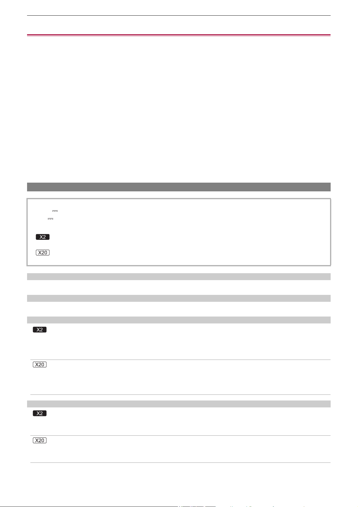
Specification – Specifications
304
Specifications
≥General: 304
≥Camera: 305
≥Memory card recorder: 307
≥Digital video: 308
≥Digital audio: 309
≥Dual codec [X2]: 309
≥Streaming: 309
≥Wi-Fi: 310
≥Video output: 310
≥Audio input: 311
≥Audio output: 311
≥Other input/output: 311
≥Monitor: 312
≥AC adaptor: 312
≥Battery charger: 312
≥Battery pack (AG-VBR59): 313
General
Ambient operating temperature
0 °C to 40 °C (32 °F to 104 °F)
Ambient operating humidity
10 % to 80 % (relative humidity, no condensation)
Mass (Weight)
Approx. 2040 g (4.50 lbs.) (main unit only (including grip belt), excluding lens hood, battery, and supplied accessories)
Approx. 2490 g (5.49 lbs.) (including lens hood, supplied battery, eye cup, 2 SD cards, microphone holder and 2 INPUT
terminal caps)
Approx. 2000 g (4.41 lbs.) (main unit only (including grip belt), excluding lens hood, battery, and supplied accessories)
Approx. 2430 g (5.36 lbs.) (including lens hood, supplied battery, eye cup, 2 SD cards, microphone holder and 2 INPUT
terminal caps)
External dimensions (W×H×D)
173 mm (6.82 q)×195 mm (7.68 q)×344 mm (13.55 q) (including lens hood, excluding eye cup and microphone holder)
211 mm (8.31 q)×195 mm (7.68 q)×390 mm (15.36 q) (including lens hood, eye cup and microphone holder)
171 mm (6.74 q)×195 mm (7.68 q)×343 mm (13.51 q) (including lens hood, excluding eye cup and microphone holder)
209 mm (8.23 q)×195 mm (7.68 q)×389 mm (15.32 q) (including lens hood, eye cup and microphone holder)
Power
7.28 V (when battery is used)
12 V (when the AC adaptor is used)
Power consumption
20.6 W (when the LCD monitor is used)
18.5 W (when the LCD monitor is used)

Specification – Specifications
305
Camera
Pickup device
1.0 type (1.0 q) MOS solid-state image sensing device for colors
Total pixels: approx. 20,920,000 pixels
Number of effective pixels
Approx. 15,030,000 pixels
Lens
Optical image stabilizer lens, motorized 20× zoom
F value: F2.8 to F4.5
Focal length: f=8.8 mm to 176 mm
35 mm conversion: f=24.5 mm to 490 mm
Filter diameter
67 mm
ND filter
<CLR>, <1/4>, <1/16>, <1/64>
Minimum object distance (M.O.D)
Approx. 1.0 m (approx. 3.3 feet) from the lens (Entire zoom range)
Approx. 0.1 m (approx. 0.33 feet) from the lens (In the vicinity of the wide limit when [FOCUS MACRO]/[MACRO] is set to
[ON])
IR cut filter
Has functionality to switch IR filter on/off (switched with [IR REC] USER button or menu)
Gain setting
•
When the [SYSTEM] menu
¨ [SHOOTING MODE] ¨ [NORMAL] is set
0dB to 24dB
• When the [SYSTEM] menu ¨ [SHOOTING MODE] ¨ [HIGH SENS.] is set
−3 dB to 24 dB
• When [S.GAIN] is assigned to a USER button, [SUPER GAIN]/[SUPER GAIN+] can be set
Color temperature setting
ATW, ATW LOCK, Ach, Bch, preset 3200 K/preset 5600 K/VAR (2000 K to 15000 K)
Shutter speed
•
When the [SYSTEM] menu
¨ [FREQUENCY] ¨ [59.94Hz] is set
59.94i/59.94p mode:
1/60 sec., 1/100 sec., 1/120 sec., 1/180 sec., 1/250 sec., 1/350 sec., 1/500 sec., 1/750 sec., 1/1000 sec., 1/1500 sec., 1/
2000 sec., 1/3000 sec., 1/4000 sec., 1/8000 sec.
29.97p mode:
1/30 sec., 1/50 sec., 1/60 sec., 1/100 sec., 1/120 sec., 1/180 sec., 1/250 sec., 1/350 sec., 1/500 sec., 1/750 sec., 1/
1000 sec., 1/1500 sec., 1/2000 sec., 1/3000 sec., 1/4000 sec., 1/8000sec.
23.98p mode:
1/24 sec., 1/48 sec., 1/50 sec., 1/60 sec., 1/100 sec., 1/120 sec., 1/180 sec., 1/250 sec., 1/350 sec., 1/500 sec., 1/
750 sec., 1/1000 sec., 1/1500 sec., 1/2000 sec., 1/3000 sec., 1/4000 sec., 1/8000 sec.

Specification – Specifications
306
• When the [SYSTEM] menu ¨ [FREQUENCY] ¨ [50.00Hz] is set
50.00i/50.00p mode:
1/50 sec., 1/60 sec., 1/100 sec., 1/125 sec., 1/180 sec., 1/250 sec., 1/350 sec., 1/500 sec., 1/750 sec., 1/1000 sec., 1/
1500 sec., 1/2000 sec., 1/3000 sec., 1/4000 sec., 1/8000 sec.
25.00p mode:
1/25 sec., 1/50 sec., 1/60 sec., 1/100 sec., 1/125 sec., 1/180 sec., 1/250 sec., 1/350 sec., 1/500 sec., 1/750 sec., 1/
1000 sec., 1/1500 sec., 1/2000 sec., 1/3000 sec., 1/4000 sec., 1/8000sec.
Slow shutter speed
•
When the [SYSTEM] menu
¨ [FREQUENCY] ¨ [59.94Hz] is set
59.94i/59.94p mode: 1/8 sec., 1/15 sec., 1/30 sec.
29.97p mode: 1/8 sec., 1/15 sec.
23.98p mode: 1/6 sec., 1/12 sec.
• When the [SYSTEM] menu ¨ [FREQUENCY] ¨ [50.00Hz] is set
50.00i/50.00p mode: 1/6 sec., 1/12 sec., 1/25 sec.
25.00p mode: 1/6 sec., 1/12 sec.
Synchro scan
•
When the [SYSTEM] menu
¨ [FREQUENCY] ¨ [59.94Hz] is set
59.94i/59.94p mode: 1/60.0 sec to 1/249.6 sec
29.97p mode: 1/30.0 sec to 1/249.8 sec
23.98p mode: 1/24.0 sec to 1/249.7 sec
• When the [SYSTEM] menu ¨ [FREQUENCY] ¨ [50.00Hz] is set
50.00i/50.00p mode: 1/50.0 sec to 1/250.0 sec
25.00p mode: 1/25.0 sec to 1/250.0 sec
VFR recording frame rate
•
When the [SYSTEM] menu
¨ [FREQUENCY] ¨ [59.94Hz] is set
2, 12, 15, 20, 22, 24, 26, 28, 30, 32, 34, 36, 45, 48, 60 (frames per second)
• When the [SYSTEM] menu ¨ [FREQUENCY] ¨ [50.00Hz] is set
2, 12, 21, 23, 25, 27, 30, 37, 50 (frames per second)
Super slow recording
•
[SYSTEM] menu
¨ [FREQUENCY] ¨ [59.94Hz]
When the number of recording pixels is 1920×1080 (FHD)
Recording frame rate 120 fps, slow motion effect 1/2 speed (in 59.94p mode), slow motion effect 1/4 speed (in 29.97p
mode), 1/5 speed (in 23.98p mode)
• [SYSTEM] menu ¨ [FREQUENCY] ¨ [50.00Hz]
When the number of recording pixels is 1920×1080 (FHD)
Recording frame rate 100 fps, slow motion effect 1/2 speed (in 50.00p mode), slow motion effect 1/4 speed (in 25.00p
mode)
Minimum illuminance of subject
0.6 lx (F2.8, [SUPER GAIN+] is enabled, when shutter speed is 1/30 sec.)

Specification – Specifications
307
Digital zoom
2× / 5× / 10× / i.ZOOM
*
* With the UHD (3840×2160) recording format: maximum 24×
With the FHD (1920×1080) recording format: maximum 32×
Lens hood
Hood with lens cover
Memory card recorder
Recording media
•
SDHC memory card (4 GB to 32 GB), SDXC memory card (exceeding 32 GB to 128 GB):
UHS-I, UHS Speed Class 3 compatible
• Refer to “Speed Class during shooting” (
ÎSpeed Class during shooting: 45).
Recording slot
2 slots
System frequency
59.94 Hz / 50.00 Hz
File format
MOV (HEVC), MOV, MP4 (HEVC), MP4, AVCHD
Recording format
•
MOV: 4:2:0 (10 bit)
UHD (3840×2160);
HEVC LongGOP 200M (Average approx. 200 Mbps)
HEVC LongGOP 150M (Average approx. 150 Mbps)
HEVC LongGOP 100M (Average approx. 100 Mbps)
• MOV: 4:2:0 (8 bit)
UHD (3840×2160);
420LongGOP 150M (Average approx. 150 Mbps)
420LongGOP 100M (Average approx. 100 Mbps)
• MOV: 4:2:2 (10 bit)
UHD (3840×2160); 422LongGOP 150M (Average approx. 150 Mbps)
FHD (1920×1080);
422LongGOP 100M (Average approx. 100 Mbps)
422LongGOP 50M (Average approx. 50 Mbps)
422ALL-I 200M (Average approx. 200 Mbps)
422ALL-I 100M (Average approx. 100 Mbps)
• MP4: 4:2:0 (10 bit)
UHD (3840×2160);
HEVC LongGOP 100M (Average approx. 100 Mbps)
HEVC LongGOP 72M (Average approx. 72 Mbps)
• MP4: 4:2:0 (8 bit)
UHD (3840×2160); 420LongGOP 72M (Average approx. 72 Mbps)
FHD (1920×1080); 420LongGOP 50M (Average approx. 50 Mbps)
Specification – Specifications
308
• AVCHD: 4:2:0 (8 bit)
FHD (1920×1080);
PS (Average approx. 25 Mbps), PH (Average approx. 21 Mbps), HA (Average approx. 17 Mbps)
HD (1280×720); PM (Average approx. 8 Mbps)
Number of recording pixels/Recording video signal
•
3840×2160/59.94p, 50.00p, 29.97p, 25.00p, 23.98p
• 1920×1080/59.94p, 50.00p, 29.97p, 25.00p, 23.98p, 59.94i, 50.00i
• 1280×720/59.94p, 50.00p
Recording and playback time
•
When using 64 GB SDXC memory card, with [FILE FORMAT] set to [MOV] or [MP4]:
With a 200 Mbps recording format: approx. 40 minutes
With a 150 Mbps recording format: approx. 55 minutes
With a 100 Mbps recording format: approx. 1 hour 20 minutes
With a 72 Mbps recording format: approx. 1 hour 50 minutes
With a 50 Mbps recording format: approx. 2 hours 40 minutes
• When using 64 GB SDXC memory card, with [FILE FORMAT] set to [AVCHD]:
With a PS recording format: approx. 5 hours 20 minutes
With a PH recording format: approx. 6 hours
With a HA recording format: approx. 8 hours 30 minutes
With a PM recording format: approx. 17 hours 10 minutes
2-slot function
Relay recording, simultaneous recording, background recording, dual codec recording
Relay recording, simultaneous recording, background recording
Still image recording
Recording format: JPEG (DCF/Exif2.2)
• For recording formats and the number of recording pixels (
ÎStill image recording function: 237)
Digital video
Number of quantizing bits
MOV(HEVC) / MP4(HEVC): 4:2:0 10bit
MOV: 4:2:2 10bit / 4:2:0 8bit
MP4 / AVCHD: 4:2:0 8bit
Video compression format
•
MOV(HEVC) / MP4(HEVC): H.265/MPEG-4 HEVC Main10 Profile
• MOV / MP4: H.264/MPEG-4 AVC High Profile
• AVCHD: H.264/MPEG-4 AVC High Profile

Specification – Specifications
309
Digital audio
Recording format
•
MOV: LPCM, 48 kHz/24 bit, 2ch
• MP4: AAC, 48 kHz/16 bit, 2ch
• AVCHD: Dolby Audio
™
, 48 kHz/16 bit, 2ch
Headroom
12 dB, 18 dB, 20 dB (switched with menu)
Dual codec [X2]
File format
MOV
Video compression format
H.264/MPEG-4 AVC High Profile, 420LongGOP
Audio compression format
LPCM, 48kHz/24 bit, 2ch
Recording format
•
When the [RECORDING] menu
¨ [DUAL CODEC SETTING] ¨ [FHD 50Mbps] is set
Main recording:
2160-29.97p, 25.00p, 23.98p/420LongGOP
Sub recording:
FHD 29.97p, 25.00p, 23.98p/420LongGOP
• When the [RECORDING] menu ¨ [DUAL CODEC SETTING] ¨ [FHD 8Mbps] is set
Main recording:
2160-29.97p, 25.00p, 23.98p/420LongGOP
1080-59.94p, 50.00p/422LongGOP
1080-59.94p, 50.00p, 59.94i, 50.00i, 29.97p, 25.00p, 23.98p/422ALL-I
Sub recording:
FHD/59.94p, 50.00p, 59.94i, 50.00i, 29.97p, 25.00p, 23.98p/420LongGOP
• The frame rate for sub recording is the same as for main recording.
Recording time (sub recording)
Streaming
Video compression format
H.264/MPEG-4 AVC Main Profile
H.264/MPEG-4 AVC High Profile
Video resolution
1920×1080 (FHD), 1280×720 (HD), 640×360, 320×180
Streaming method
Unicast, Multicast
[DUAL CODEC SETTING]
Capacity of memory cards
64 GB 128 GB
[FHD 50Mbps] Approx. 2 hours 40 minutes Approx. 5 hours 20 minutes
[FHD 8Mbps] Approx. 17 hours 10 minutes Approx. 35 hours
Specification – Specifications
310
Frame rate
•
When set to the [SYSTEM] menu
¨ [FREQUENCY] ¨ [59.94Hz]:
60 fps, 30 fps, 24 fps
• When set to the [SYSTEM] menu ¨ [FREQUENCY] ¨ [50.00Hz]:
50 fps, 25 fps
Bit rate
24 Mbps, 20 Mbps, 16 Mbps, 14 Mbps, 8 Mbps, 6 Mbps, 4 Mbps, 3 Mbps, 2 Mbps, 1.5 Mbps, 1 Mbps, 0.7 Mbps, 0.5 Mbps
Audio compression format
AAC-LC: 48 kHz/16 bit, 2ch
Supported protocol
RTSP / RTP / RTMP / RTMPS
Wi-Fi
Compliance standard
IEEE802.11b/g/n compliant
Frequency range used (central frequency)
2412 MHz to 2462 MHz [1 to 11ch]
Encryption method
Wi-Fi compliant WPA
™
/ WPA2
™
Access method
Infrastructure mode
Video output
<SDI OUT> terminal
•
BNC terminal ×1
0.8 V [p-p], 75 Ω, 3G/1.5G HD-SDI compatible
• Supports time code output and SDI remote recording control
• Output format (4:2:2 10bit output)
1920×1080: 59.94p LEVEL-A, 50.00p LEVEL-A, 59.94i, 50.00i, 29.97p, 29.97PsF, 25.00p, 25.00PsF, 23.98p, 23.98PsF
1280×720: 59.94p, 50.00p
<HDMI> terminal
•
HDMI type A terminal ×1 (not compatible with VIERA Link)
• Supports time code output and remote recording control
• Output format (4:2:2 10bit output)
3840×2160: 59.94p, 50.00p, 29.97p, 25.00p, 23.98p
1920×1080: 59.94p, 50.00p, 59.94i, 50.00i, 29.97p, 25.00p, 23.98p
1280×720: 59.94p, 50.00p
720×480: 59.94p
720×576: 50.00p
Specification – Specifications
311
Audio input
Built-in microphone
Stereo microphone
<AUDIO INPUT1>/<AUDIO INPUT2> terminal
XLR (3-pin) ×2
Input high impedance,
<LINE> / <MIC> / <i48V> (Switched with <INPUT 1> / <INPUT 2> switch)
• <LINE>: 4 dBu, 0 dBu (switched with menu)
• <MIC>: −40 dBu, −50 dBu, −60 dBu (switched with menu)
Audio output
<SDI OUT> terminal
LPCM 2ch
<HDMI> terminal
LPCM 2ch
Headphone terminal
3.5 mm diameter stereo mini jack × 1
Speaker
20 mm diameter, round ×1
Other input/output
<TC IN/OUT> terminal
•
BNC terminal ×1
Used as the input and output terminals (switched with menu)
• Input: 1.0 V to 4.0 V [p-p], 10 kΩ
• Output: 2.0 V±0.5 V [p-p], low impedance
<REMOTE> terminal
2.5 mm diameter super mini jack × 1
Remote control terminal of serial communication
Analogue remote control used for previous Panasonic models cannot be used.
USB terminal
USB Type-C
®
×1, USB3.1 Gen1, Host/device combined (switched with menu)
Device: USB mass storage functionality (read only)
Host: Supports bus power (5 V, 0.9 A)
USB tethering functionality
USB ethernet adaptor functionality
<LAN> terminal
RJ-45×1: 1000BASE-T / 100BASE-TX
<DCIN12V> terminal
DC12 V, EIAJ type 4
Specification – Specifications
312
Monitor
LCD monitor
8.8 cm (3.5 q) LCD monitor: approx. 2,760,000 dots
Viewfinder
1.0 cm (0.39 q) OLED (organic EL display): approx. 2,360,000 dots
Video display area: approx. 1,770,000 dots
AC adaptor
Ambient operating temperature
0 °C to 40 °C (32 °F to 104 °F)
Ambient operating humidity
10 % to 90 % (relative humidity, no condensation)
Mass (Weight)
Approx. 225 g (Approx. 0.496 lbs.)
External dimensions (W×H×D)
115 mm×37 mm×57 mm (4-1/2 q×1-7/16 q×2-1/4 q) (excluding the DC cable section)
Battery charger
Charging current
Maximum 4000 mA
Ambient operating temperature
0 °C to 40 °C (32 °F to 104 °F)
Ambient operating humidity
10 % to 80 % (relative humidity, no condensation)
Mass (Weight)
Approx. 230 g (Approx. 0.51 lbs.)
External dimensions (W×H×D)
130 mm×48 mm×107 mm (5-1/8 q×1-7/8 q×4-3/16 q)
Power source
100 V – 240 V 50 Hz/60 Hz, 1.2 A
79 VA (100 V ) – 99 VA (240 V )
Power output
12 V 3.0 A
Input voltage
12 V 3.0 A
Output voltage
8.4 V 4.0 A

Specification – Specifications
313
Battery pack (AG-VBR59)
Charging current
Maximum 4000 mA
Ambient operating humidity
0 % to 80 % (relative humidity, no condensation)
Mass (Weight)
Approx. 230 g (Approx. 0.507 lbs.)
External dimensions (W×H×D)
41.3 mm×51.3 mm×69.6 mm (1-5/8 q×2 q×2-3/4 q)
The symbols on this product (including the accessories) represent the following:
Voltage/capacity
7.28 V 5900 mAh 43 Wh
AC
DC
Class II equipment (The construction of the product is double-insulated.)