Operating Instructions
Memory Card Camera-Recorder
Before using this product, be sure to read “Read this first!” (pages 2 to 6).
Before operating this product, please read the instructions carefully and save this manual for future use.
ENGLISH
DVQP1830XA
W0219HO2109 -YI
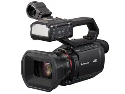
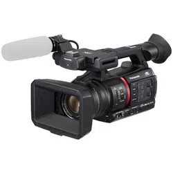
Model No. AG-CX350
Model No. AJ-UPX360ED
P PJ EN ED AN PX
Read this rst!
– 2 –
Read this rst!
indicates safety information.
CAUTION
RISK OF ELECTRIC SHOCK
DO NOT OPEN
CAUTION: TO REDUCE THE RISK OF ELECTRIC SHOCK,
DO NOT REMOVE COVER (OR BACK).
NO USER-SERVICEABLE PARTS INSIDE.
REFER TO SERVICING TO QUALIFIED SERVICE PERSONNEL.
The lightning flash with arrowhead symbol,
within an equilateral triangle, is intended to
alert the user to the presence of uninsulated
“dangerous voltage” within the product’s
enclosure that may be of sufficient magnitude
to constitute a risk of electric shock to
persons.
The exclamation point within an equilateral
triangle is intended to alert the user to
the presence of important operating and
maintenance (servicing) instructions in the
literature accompanying the appliance.
WARNING:
• To reduce the risk of fire or electric shock, do not
expose this equipment to rain or moisture.
• To reduce the risk of fire or electric shock, keep
this equipment away from all liquids. Use and
store only in locations which are not exposed
to the risk of dripping or splashing liquids, and
do not place any liquid containers on top of the
equipment.
WARNING:
Always keep memory cards (optional accessory)
or accessories (microphone holder screws) out of
the reach of babies and small children.
CAUTION:
To reduce the risk of fire or electric shock and
annoying interference, use the recommended
accessories only.
CAUTION:
The mains plug of the power supply cord shall
remain readily operable.
The AC receptacle (mains socket outlet) shall be
installed near the equipment and shall be easily
accessible.
To completely disconnect this equipment from the
AC mains, disconnect the power cord plug from
the AC receptacle.
CAUTION:
Excessive sound pressure from earphones and
headphones can cause hearing loss.
CAUTION:
Danger of explosion or fire if battery is incorrectly
replaced or mistreated.
• Do not disassemble the battery or dispose of it
in fire.
• Do not store in temperatures over 60°C (140°F).
• Do not expose the battery to excessive heat
such as sunshine, fire or the like.
For Battery Pack
• Use specified charger.
• Replace only with same or specified type.
CAUTION:
In order to maintain adequate ventilation, do
not install or place this unit in a bookcase, built-
in cabinet or any other confined space. To
prevent risk of electric shock or fire hazard due to
overheating, ensure that curtains and any other
materials do not obstruct the ventilation.
CAUTION:
Do not lift the unit by its handle while the tripod is
attached. When the tripod is attached, its weight
will also affect the unit’s handle, possibly causing
the handle to break and hurting the user. To carry
the unit while the tripod is attached, take hold of
the tripod.
CAUTION:
Do not leave the unit in direct contact with the skin
for long periods of time when in use.
Low temperature burn injuries may be suffered if
the high temperature parts of this unit are in direct
contact with the skin for long periods of time.
When using the equipment for long periods of
time, make use of the tripod.
CAUTION:
Keep metal objects (such as necklaces and
hairpins) away from the battery.
Short-circuiting may occur across the terminals,
causing the battery to heat up, and you may
seriously burn yourself if you touch the battery in
this state.
CAUTION:
Do not jar, swing, or shake the unit by its handle
while the conversion lens or another accessory is
attached.
Due to the added weight of the conversion lens,
any strong jolt to the handle may damage the unit
or result in personal injury.
Read this rst!
– 3 –
indicates safety information.
CAUTION:
This apparatus can be operated at a voltage in the range of 100-240 V AC.
Voltages other than 120 V are not intended for U.S.A. and Canada.
Operation at a voltage other than 120 V AC may require the use of a different AC plug. Please contact either
a local or foreign Panasonic authorized service center for assistance in selecting an alternate AC plug.
FCC NOTICE (USA)
Supplier’s Declaration of Conformity
Trade Name: Panasonic
Model Number: AG-CX350
Responsible Party: Panasonic Corporation of North America
Two Riverfront Plaza Newark NJ07102
Support contact: 1-800-524-1448
This device complies with Part 15 of the FCC Rules. Operation is subject to the following two conditions:
(1) This device may not cause harmful interference, and (2) this device must accept any interference
received, including interference that may cause undesired operation.
FCC Warning:
To assure continued FCC emission limit compliance, follow the attached installation instructions and the
user must use only shielded interface cables when connecting to host computer or peripheral devices. Also,
any unauthorized changes or modifications to this equipment could void the user’s authority to operate this
device.
FCC Caution:
This equipment has been tested and found to comply with the limits for a Class B digital device, pursuant
to Part 15 of the FCC Rules. These limits are designed to provide reasonable protection against harmful
interference in a residential installation. This equipment generates, uses and can radiate radio frequency
energy and, if not installed and used in accordance with the instructions, may cause harmful interference
to radio communications. However, there is no guarantee that interference will not occur in a particular
installation. If this equipment does cause harmful interference to radio or television reception, which can be
determined by turning the equipment off and on, the user is encouraged to try to correct the interference by
one or more of the following measures:
f Reorient or relocate the receiving antenna.
f Increase the separation between the equipment and receiver.
f Connect the equipment into an outlet on a circuit different from that to which the receiver is connected.
f Consult the dealer or an experienced radio/TV technician for help. The user may nd the booklet
“Something About Interference” available from FCC local regional ofces helpful.
NOTIFICATION (Canada)
CAN ICES-3(B)/NMB-3(B)
The rating plate is on the underside of the Camera Recorder, Battery Charger and AC Adaptor.
Read this rst!
– 4 –
IMPORTANT SAFETY INSTRUCTIONS
1) Read these instructions.
2) Keep these instructions.
3) Heed all warnings.
4) Follow all instructions.
5) Do not use this apparatus near water.
6) Clean only with dry cloth.
7) Do not block any ventilation openings. Install in accordance with the manufacturer’s instructions.
8) Do not install near any heat sources such as radiators, heat registers, stoves, or other apparatus (including amplifiers) that
produce heat.
9) Do not defeat the safety purpose of the polarized or grounding-type plug. A polarized plug has two blades with one wider
than the other. A grounding-type plug has two blades and a third grounding prong. The wide blade or the third prong are
provided for your safety. If the provided plug does not fit into your outlet, consult an electrician for replacement of the
obsolete outlet.
10) Protect the power cord from being walked on or pinched particularly at plugs, convenience receptacles, and the point
where they exit from the apparatus.
11) Only use attachments/accessories specified by the manufacturer.
12) Use only with the cart, stand, tripod, bracket, or table specified by the manufacturer, or sold with the apparatus.
When a cart is used, use caution when moving the cart/ apparatus combination to avoid injury from tip-over.
13) Unplug this apparatus during lightning storms or when unused for long periods of time.
14) Refer all servicing to qualified service personnel. Servicing is required when the apparatus has been damaged
in any way, such as power-supply cord or plug is damaged, liquid has been spilled or objects have fallen into the
apparatus, the apparatus has been exposed to rain or moisture, does not operate normally, or has been dropped.
For USA and Canada
A lithium ion/polymer battery that is recyclable powers the product you have purchased.
Please call 1-800-8-BATTERY for information on how to recycle this battery.
Read this rst!
– 5 –
Brazil Only
Brasil Apenas
r
Manuseio de baterias usadas
BRASIL
Após o uso, as pilhas e /ou baterias poderão
ser entregues ao estabelecimento comercial
ou rede de assistência técnica autorizada.
Cobrir os terminais positivo (+) e negativo (-) com uma fita isolante adesiva, antes de depositar numa caixa
destinada para o recolhimento. O contato entre partes metálicas pode causar vazamentos, gerar calor, romper a
blindagem e produzir fogo.
Não desmonte, não remova o invólucro, nem amasse a bateria. O gás liberado pela bateria pode irritar a
garganta, danificar o lacre do invólucro ou o vazamento provocar calor, ruptura da blindagem e produzir fogo
devido ao curto circuito dos terminais. Não incinere nem aqueça as baterias, elas não podem ficar expostas a
temperaturas superiores a 100°C (212°F). O gás liberado pela bateria pode irritar a garganta, danificar o lacre
do invólucro ou o vazamento provocar calor, ruptura da blindagem e produzir fogo devido ao curto circuito dos
terminais provocado internamente.
Evite o contato com o liquido que vazar das baterias. Caso isto ocorra, lave bem a parte afetada com bastante
água. Caso haja irritação, consulte um médico.
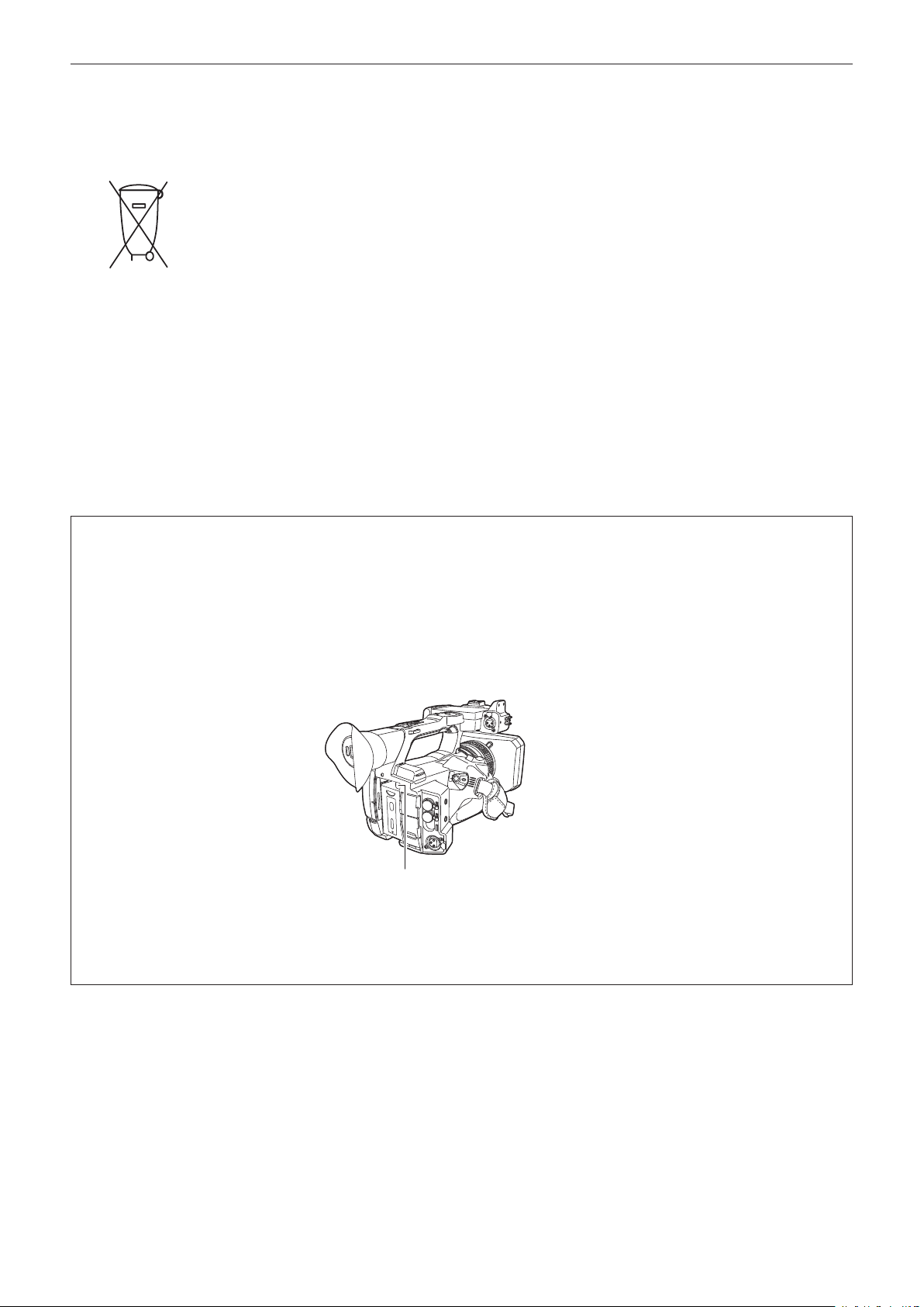
To remove the battery
Para remover a bateria
Main Power Battery (Lithium ion Battery)
Bateria Principal de Energia
(Refer to page 32 for the detail.)
Press the battery release button.
Pressione o botão para liberar a bateria.
Battery release button
Botão de liberação da bateria
Back-up Battery (Lithium Battery)
• For the removal of the battery for disposal at the end of its service life, please consult your dealer.
Read this rst!
– 6 –
r
Batteries that may be used with this product (as of October 2019)
Panasonic AG-VBR59 / AG-VBR89 / AG-VBR118 / VW-VBD58 batteries may be used with this product.
It has been found that counterfeit battery packs which look very similar to the genuine product are made
available to purchase in some markets. Some of these battery packs are not adequately protected with internal
protection to meet the requirements of appropriate safety standards. There is a possibility that these battery
packs may lead to fire or explosion. Please be advised that we are not liable for any accident or failure occurring
as a result of use of a counterfeit battery pack. To ensure that safe products are used we would recommend that
a genuine Panasonic battery pack is used.
Battery Charger / AC Adaptor
Disconnect the AC mains plug from the AC mains socket when not in use.
Information on Disposal in other Countries outside the European Union
EU
These symbols are only valid in the European Union. If you wish to discard these items, please contact your
local authorities or dealer and ask for the correct method of disposal.
r The symbols on this product (including the accessories) represent the following:
d AC
e DC
ON
Standby (OFF)
Class II equipment (The construction of the product is double-insulated.)

– 7 –
Trademark
f SDXC logo is a trademark of SD-3C, LLC.
f AVCHD, AVCHD Progressive, and AVCHD Progressive logo are trademarks of Panasonic Corporation and Sony Corporation.
f This is manufactured based on license from Dolby Laboratories, Inc. Dolby, Dolby Audio, and the double-D symbol are trademarks of Dolby
Laboratories.
f The terms HDMI and HDMI High-Denition Multimedia Interface, and the HDMI Logo are trademarks or registered trademarks of HDMI Licensing
Administrator, Inc. in the United States and other countries.
f Microsoft
®
and Windows
®
are registered trademarks or trademarks of Microsoft Corporation in the United States and/or other countries.
f Screenshots are used according to Microsoft Corporation guidelines.
f Intel
®
, Pentium
®
, Celeron
®
, and Intel
®
Core
TM
are trademarks of Intel Corporation in the United States and/or other countries.
f Mac and Mac OS are trademarks of Apple Inc. registered in the United States and/or other countries.
f iPhone/iPad are trademarks of Apple Inc. registered in the United States and/or other countries.
f App Store is a service mark of Apple Inc.
f Android and Google Play are trademarks or registered trademarks of Google LLC.
f Wi-Fi
®
is a registered trademark of Wi-Fi Alliance
®
.
f WPA
TM
and WPA2
TM
are trademark of Wi-Fi Alliance
®
.
f NDI
®
is a registered trademark of NewTek, Inc.
f All other names, company names, product names, etc., contained in this instruction manual are trademarks or registered trademarks of their
respective owners.
License
f This product is licensed under the AVC Patent Portfolio License. All other acts are not licensed except private use for personal and non-prot purposes
such as what are described below.
-To record video in compliance with the AVC standard (AVC Video)
-To play back AVC Video that was recorded by a consumer engaged in a personal and non-commercial activity
-To play back AVC Video that was obtained from a video provider licensed to provide the video
Visit the MPEG LA, LLC website (http://www.mpegla.com/) for details.
f Separate license contract with MPEG-LA is required to record in a memory card with this product and to distribute that card to end users for a prot.
The end user mentioned here indicates a person or organization that handles contents for a personal use.
Software information about this product
1 This product includes software licensed under GNU General Public License (GPL) and GNU Lesser General Public License (LGPL), and
customers are hereby notied that they have rights to obtain, re-engineer, and redistribute the source code of these software.
2 This product includes software licensed under MIT-License.
3 This product includes software developed by the OpenSSL Project for use in the OpenSSL Toolkit (http://www.openssl.org/).
4 This product includes software licensed under OpenBSD License.
5 This software is based in part on the work of the Independent JPEG Group.
6 This product includes software licensed under the MOZILLA PUBLIC LICENSE.
For details on each license, refer to the terms of license.
The terms of license can be displayed using the following method.
f Select the [OTHERS] menu → [USB DEVICE] → [SERVICE MODE] → [YES].
Select “LICENSE.TXT” in the external drive recognized by the computer.
For details on these descriptions (originally provided in English) and how to obtain the source code, visit the following website.
https://pro-av.panasonic.net/
We do not accept inquiries about the details of the source code obtained by the customer.
Excluding the open source software licensed based on GPL/LGPL, etc., transferring, copying, reverse assembling, reverse compiling, and reverse
engineering of the software included in the camera is prohibited. Also, exporting of any software included in the camera against the export laws and
regulations is prohibited.
How to read this document
r Illustrations
f Illustrations of the product appearance, menu screens, etc., may vary from the actual.
r Conventions used in this manual
f Words and phrases in [ ] brackets indicate content displayed in the LCD monitor.
f Words and phrases in < > brackets indicate design text used on this camera, such as button names.
r Reference pages
f Reference pages in this document are indicated by (page 00).
r Terminology
f SD memory card, SDHC memory card, and SDXC memory card are referred to only as “SD card” unless distinguished otherwise.
f A memory card with the “microP2” logo is referred to as a “microP2 card”.
f SD card and microP2 card are referred to only as a “memory card” unless distinguished otherwise.
f Video that is created during a single recording operation is referred to as a “clip”.

Contents
– 8 –
Contents
Read this rst! 2
Chapter 1 Overview 10
Before using the camera
11
Accessories 14
When turning on the power for the rst time 15
[AREA SETTINGS] 15
[TIME ZONE] 16
[CLOCK SETTING] 16
Use of the camera on a system 17
Basic conguration devices 17
Expanded conguration devices 17
What you can do with this camera 18
Recording to the memory card 18
Linking to external devices 18
Connecting to the network 19
Chapter 2 Description of Parts 20
Camera
21
Left side 21
Right side 22
Front side 2 4
Rear side 25
Top side 26
Basic operation 28
Multidial operation 28
Touch operation of the LCD monitor 28
Chapter 3 Preparation 29
Power supply
30
Charging the battery 30
Attaching and removing the battery 32
Using the AC adaptor 33
Mounting accessories 34
Adjusting the grip belt 34
Attaching the shoulder strap 34
Mounting the lens hood 34
Mounting the eye cup 3 5
Mounting the external microphone 36
Attaching a tripod 36
Mounting accessories 37
Turning on/off the power 38
How to turn on the power 38
How to turn off the power 3 8
Charging the built-in battery 39
Setting the date/time of the internal clock 40
Preparing the memory card 41
Memory cards supported by the camera 41
Preventing unintentional erasing 42
Status of the card access lamp and memory card 42
Inserting/removing the memory card 42
Formatting the memory card 43
Recording time of the memory card 43
Handling the recording data 4 4
Setting of time data 48
Denition of time data 48
User bits settings 48
Setting the time code 49
Presetting the time code to external 50
Supplying the time code externally 51
Assigning function to the USER buttons 52
Functions assigned to USER buttons 52
Checking the function assigned to the USER buttons 53
Adjusting and setting the LCD monitor 54
Using the LCD monitor 54
Adjusting the LCD monitor 54
Mirror shooting 54
Adjusting and setting the viewnder 55
Using the viewnder 55
Adjusting the viewnder 55
Tally lamp
56
Chapter 4 Operation 57
Basic operation of the screen
58
Major button operation and screen display 58
Major button operation and switching screen 59
Operating each screen 60
Camera image screen 60
Thumbnail screen 60
Operation icon screen 60
Basic operation of the menu 61
Conguration of the menu 61
Displaying the menu 62
Operating the menu 63
Initializing the menu 64
Menu settings 65
[THUMBNAIL] menu 65
[CAMERA] menu 65
[SCENE FILE] menu 6 9
[AUDIO] menu 79
[VIDEO OUT/LCD/VF] menu 81
[RECORDING] menu 90
[NETWORK] menu 92
[SYSTEM] menu 98
[OTHERS] menu 99
[OPTION] menu 101
Factory setting value of the scene le 102
[SCENE FILE] menu 102
Target items for scene le/setup le/initialization 105
[THUMBNAIL] menu 105
[CAMERA] menu 105
[SCENE FILE] menu 106
[AUDIO] menu 108
[VIDEO OUT/LCD/VF] menu 108
[RECORDING] menu 109
[NETWORK] menu 110
[SYSTEM] menu 111
[OTHERS] menu 111
[OPTION] menu 111
Handling setting data 112
Scene les 112
Setup le 11 3
Chapter 5 Shooting 115
Shooting
116
Selecting the resolution, codec, and frame rate for recording
video 117
Adjustable settings when shooting 119
Iris 119
Gain 119
Super gain 119
Brightness adjustment 11 9
Macro 119
Focusing (manual focus) 119
Area mode function 120
Adjusting the white and black balance 121
White balance adjustment 121
Black balance adjustment 122
Using the zoom function 124
Adjusting the zoom position 124
Image quality adjustment 125
Detail function 125
Skin tone function 125
RB gain control function 125
Chroma setting function 126
Matrix function 126
Color correction function 127
Black control function 127
Gamma function 127
Knee function 128
White clip function 128
Variable frame rate (VFR) recording function/super slow
recording function 129
Variable frame rate (VFR) 129
Super slow 129
Audio input 130
Switching the audio input 130
When using the built-in microphone 130
When using an audio device or an external microphone
130
Adjusting the audio recording level 131
Monitoring the audio 131
Conrming audio input setting 132
Special recording function 133
Pre-recording 133

Contents
– 9 –
Relay recording 133
Simultaneous recording 134
Background recording 135
Interval recording 136
IR recording 136
Convenient shooting functions 137
Zebra patterns display 137
Displaying the center marker 137
Displaying the safety zone marker 138
Displaying frame marker 138
Focus assist function 138
Optical image stabilizer function 140
Dynamic range stretcher function 140
Time stamp function 140
Waveform monitor function 141
Digital zoom function 141
Level gauge 142
Color bars 142
Operation icon screen display 143
Displaying the operation icon screen 143
Multi manual function 144
Displaying the operation icon screen 144
Setting the variable value for the white balance 144
Setting the shutter speed 144
Setting the synchro scan shutter speed 144
Setting the frame rate of the variable frame rate recording
function 145
Adjusting the area size/area position of the area mode
function 145
Adjusting the width of the auto focus area 145
Chapter 6 Playback 146
Thumbnail operation
147
Thumbnail operation overview 147
Thumbnail screen 147
Copying clips 150
Deleting clips 151
Protecting clips 152
Restoring clips 152
Playing back clips 153
Useful playback function 155
Resume play 155
Still image recording function 156
Chapter 7 Output and Screen Display 157
Output format
158
Format that can be output from the <SDI OUT> terminal 158
Format that can be output from the <HDMI> terminal 158
Screen status display 160
Screen display during shooting 160
Screen display during playback 164
Checking and displaying shooting status 165
Mode check display 166
Chapter 8 Connecting to External Devices 169
Connecting with headphones and TV/monitor
170
Headphones 170
Remote control 170
TV/monitor 171
Connection function via the <USB3.0 DEVICE>/<USB2.0
HOST> terminal 172
Connection with a computer in card reader mode 172
Remote operation by iPhone/iPad or Android terminal 173
Chapter 9 Network Connection 174
Network connection
175
Available functions 175
Preparing for connection 176
For the wireless module 176
For the wired LAN 176
Network settings 177
Wireless LAN settings 177
Wired LAN settings
178
Specifying the network settings using the settings tool 179
Conrming the network status 181
Connecting to the iPhone/iPad or Android terminal 182
Mounting the wireless module 182
Camera settings 182
Preparing the CX ROP app 182
Connecting to the CX ROP application 183
Operation while the CX ROP app is connected 183
Streaming function 184
Camera settings 184
Starting streaming with an operation from the application
software 185
Starting streaming with an operation on the camera 185
Entering the setting using the setting tool 187
NDI|HX function 188
Camera settings 188
Using P2 Cast 190
Procedure for using 190
Streaming from P2 Cast 190
Chapter 10 Notes 191
Frequently asked questions
192
Power supply 192
Battery 192
Battery charger 192
Memory card 192
Shooting 192
Playback 193
Others 193
Warning system 194
Cases indicated by error messages 194
Recording function that cannot be used simultaneously 198
Updating the camera rmware 199
Cleaning and storing 200
Cleaning the camera body 200
Cautions when storing the camera recorder 200
Chapter 11 Specication 201
Dimensions
202
Specications 203
General 203
Camera unit 203
Memory card recorder 204
Digital video 205
Digital audio 205
Streaming 205
Video output 205
Audio input/output 206
Other input/output 206
Monitor 206
AC adaptor 206
Battery charger (AG-BRD50) 206
Battery pack (AG-VBR59) 206
Index 208

Before using the camera, read this chapter.
Chapter 1 Overview

– 11 –
Chapter 1 Overview — Before using the camera
Before using the camera
r Before using the camera, always check if the built-in battery is not consumed, and then set the date/time.
The date of the internal clock of the camera resets to January 1, 2019 if the built-in battery is exhausted. This may result in the meta data of the clip not
being recorded correctly, and it may not display correctly in the thumbnail screen.
Connect the AC adaptor to the camera or mount a battery when recharging the built-in battery.
The date/time set on the camera is maintained for approximately four months when left in this state for approximately 24 hours.
(The built-in battery is charged even when the power switch is set to < j > (ON))
For details about setting the time zone and date/time, refer to [TIME ZONE] (page 16) and [CLOCK SETTING] (page 16).
r When using this product during rain or snow or when at the beach, be careful that water does not get inside the camera.
Water causes damage to the camera and memory card. (Repair may be impossible)
r Keep the camera away from devices that produce magnetism (TVs, TV games, etc.).
f Do not use the camera on top of a TV or around it. Image or audio of the camera may be distorted by the electromagnetic wave emitted from a TV.
f The recorded content may be damaged or image may be distorted by a strong magnetic eld produced by speaker or large motor.
f Do not use the camera on top of a microcomputer or around it. Image or audio of the camera may be distorted by the electromagnetic wave emitted
from a microcomputer.
f The camera may not operate properly due to a harmful effect from a device producing magnetism. In such case, turn off the camera and either remove
the battery or unplug the AC adaptor from the power outlet. Then, mount the battery or connect the AC adaptor again. After that, turn on the camera.
r Do not use the camera near a radio transmitter or high-voltage device.
Using the camera recorder near a radio transmitter or high-voltage device may cause harmful effect to the recorded video or audio.
r Take care so sand and/or dust do not get inside the camera when using the camera at the beach, etc.
Sand and dust may damage the camera and memory card. (Be careful when inserting or removing the memory card)
r AC adaptor, battery charger, and battery
f It may take more time to charge or may not be able to charge when the temperature of the battery is extremely high or extremely low.
f When the charging lamp continues to ash in orange, check if there is any debris, foreign object, or dirt attached to the terminal section of the battery
or the battery charger, and reconnect it correctly. Always disconnect the power plug from the power outlet before removing the debris, foreign object,
or dirt attached to the terminal section.
f The charging lamp will ash in orange when the temperature of the battery is extremely high or low.
Then, charging will start automatically after the battery reaches chargeable temperature.
f If the charging lamp continues to ash even when the battery is at its optimal temperature, the battery or battery charger may be damaged. Consult
the dealer.
f Noise may be generated in radio when the camera is used close to a radio (especially when receiving AM). Keep a distance of 1 m or more when
using.
f Oscillating sound may generate inside the AC adaptor or the battery charger during the use, but this is not a malfunction.
f Always disconnect the power plug from the power outlet after the use. (Power of approximately 0.1 W is consumed by the AC power itself if kept
connected)
f Do not get the terminal section of the AC adaptor, the battery charger, or the battery dirty. Install the device close to the power outlet so the
disconnection device (power plug) can be easily reached.
r Memory cards
f The surface of camera or the memory card may get slightly hot when used for a long period of time, but this is not a malfunction.
f The amount of memory included on the label of the memory card is the total amount of memory below.
-Capacity to protect and manage copyright
-Capacity usable as the normal memory on the camera or a PC.
f Do not give a strong impact to, bend, or drop the memory card.
f Memory card data may become destroyed or erased in the following cases.
-Electrical noise or static electricity
-Malfunction of the camera or the memory card
f Do not perform the following operations when accessing the memory card (the card 1 access lamp/card 2 access lamp is ashing in orange).
-Removing the memory card
-Disconnecting battery or the AC adaptor without turning off the camera
-Apply vibration of impact
r Take care not to drop the camera when carrying the camera.
f Strong impact will damage the camera, and it may not operate properly.
f Hold the handle or grip when carrying the camera, and handle it carefully.
r Do not apply insecticide or volatile material to the camera.
f The camera may deform or the paint may peel off when insecticide or volatile material is applied.
f Do not allow the camera to remain in contact with a rubber or vinyl object for a long period of time.

– 12 –
Chapter 1 Overview — Before using the camera
r Disconnect the battery or disconnect the AC cable from the power outlet after the use.
r Battery characteristics
The battery is a rechargeable lithium-ion battery. It produces electrical energy via an internal chemical reaction. This chemical reaction is effected by
the ambient temperature and humidity. The usable time of the battery becomes shorter when the temperature gets higher or lower. When used in an
environment with extremely low temperature, it can only be used for approximately ve minutes.
When the battery is in an extremely hot environment, its protective function will operate and the camera recorder cannot be used temporarily.
r After using the camera recorder, be sure to remove the battery.
Securely remove the battery from the camera.
(Minute current is consumed even if the camera is turned off when the battery is kept mounted)
The battery will become over discharge and may become unusable even if it is recharged when the battery is kept mounted for long period of time.
Do not remove the battery when the power is turned on.
Turn off the power and remove the battery after the operation lamp goes completely out.
r Take proper care of the battery terminal.
Do not allow dust or foreign objects on the battery terminal.
Conrm that the battery and its terminal section is not deformed when the battery is dropped by mistake.
Do not mount the deformed battery into a camera or mount to the battery charger. This may damage the camera or the battery charger.
r Cautions when throwing memory cards away or transferring them to others
Formatting memory cards or deleting data using the functions of the camera or a computer will merely change the le management information: it will
not completely erase the data on the cards.
It is recommended to completely erase the data in following method when discarding/conveying.
f Physically destroy the memory card itself
f Completely erase the data in the memory card using a commercially available data erasing software for PC, etc.
Users are responsible for managing the data stored in their memory card.
r LCD monitor and viewnder
f Do not continuously display the same image or text on the LCD monitor for a long period of time. The image may be burned on to the screen. It will
return to normal after leaving the camera recorder turned off for several hours.
f Condensation sometimes forms on the LCD panel of the LCD monitor in locations subject to extreme temperature differences. If this happens, wipe
with a soft, dry cloth.
f The LCD monitor will be slightly darker than normal immediately after the power is turned on when the camera is very cold. It will return to its regular
brightness when the internal temperature increases.
f The LCD monitor and viewnder (organic EL) are managed with high precision so that at least 99.99% of the dots are effective pixels and 0.01% or
less are invalid pixels and always lit. This is not a malfunction and it has no effect whatsoever on the recorded images.
f The viewnder for this camera uses an organic EL. The image may burn into the screen if the same image or letters are left displayed on the screen
for a long time. There is no problem with the recorded images.
Switch the screen by turning off the screen or by using the eye sensor, etc.
f It may become difcult to see or difcult to recognize the touch when a LCD protection sheet is afxed.
r Caution regarding laser beams
The MOS sensor may be damaged if the MOS sensor is subjected to light from a laser beam.
Take sufcient care to prevent laser beams from striking the lens when shooting in an environment where laser devices are used.
r Note the following points.
f If you prepare to record important images, always shoot some advance test footage to verify that both pictures and sound are being recorded
normally.
f Panasonic will not assume liability when video or audio recording fails due to a malfunction of the camera or the memory card during the use.
f Set the calendar (datetime of the internal clock) and the time zone, or check the setting before recording. This will have an effect on the management
of the recorded contents.
r Exemption of liability
Panasonic is not liable in any way regarding following.
1 Incidental, special, or consequential damages caused directly or indirectly by the camera
2 Damages, breakage of the camera, etc., caused by misuse or carelessness of the customer
3 When disassembly, repair, or modication of the camera is performed by the customer
4 Inconveniences, damnication, or damages by not being able to record and/or display the video due to any reasons including failure or
malfunction of the camera
5 Inconveniences, damnication, or damages resulting from malfunction of the system combining with any third party equipment
6 A liability claim or any claim for a privacy violation by an individual or a group that was the subject of the video that the customer has
shot (including recording) that became public by any reason (including using with the network user authentication turned OFF)
7 The registered information is lost due to any reason (including initializing this camera because the authentication information such as
user name or password is forgotten)
r Cautions regarding network
Since this camera is used connected to a network, following mischief may occur.
1 Leaking or divulging of information through the camera
2 Fraudulent operation of the camera by a malicious third party

– 13 –
Chapter 1 Overview — Before using the camera
3 Obstruction and/or stopping of the camera by a malicious third party
It is customer’s responsibility to take sufcient network security measures including the following to prevent damage caused by such mischief. Please
note that Panasonic is not liable in any way for damage caused by such mischief.
f Use the camera on a network where safety is secured by using a rewall, etc.
f When using the camera on a system where a PC is connected, make sure that checking and cleaning of infection by computer virus and malicious
program is performed periodically.
f In order to prevent malicious attacks, use the authentication system and change the default setting values by using 8 characters or more including 3
or more character types for the authentication information (such as user name and password) so that a third party cannot guess your authentication
information.
f Store the authentication information (user name, password, etc.) appropriately so it is not visible to the third party.
f Periodically change the authentication information (user name, password, etc.) and do not use the same authentication information as other accounts.
f To prevent the setting information in the camera to leak to the network, execute measure such as restricting the access with user authentication, etc.
f Do not install in a location where the camera, cable, etc., can be easily damaged.
r Security
Take caution so the camera or memory card is not stolen, lost, or neglected. Note that Panasonic is not liable to leakage, falsication, or loss of
information caused by them.
– 14 –
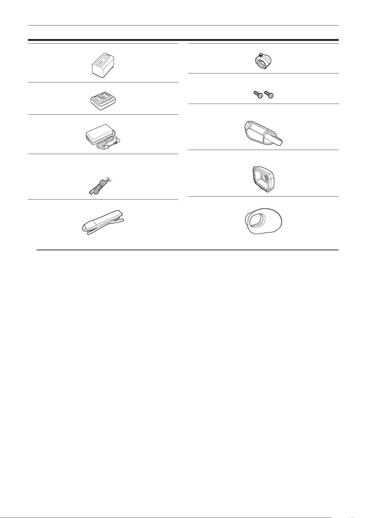
Chapter 1 Overview — Accessories
Accessories
Battery (Parts No.: AG-VBR59) (page 30)
Battery charger (Parts No.: AG-BRD50) (page 30)
AC adaptor (page 30)
AC cable (page 30)
f For AC adaptor
Shoulder strap (page 34)
Microphone holder (page 36)
Microphone holder screws (page 36)
f Length 12 mm (x 2)
Grip belt (page 34)
f Already mounted to the camera.
Lens hood (page 34)
f Already mounted to the camera.
Eye cup (page 35)
@
NOTE
t Appropriately discard the AC cable cap (if attached) and packing materials after taking the product out.
– 15 –
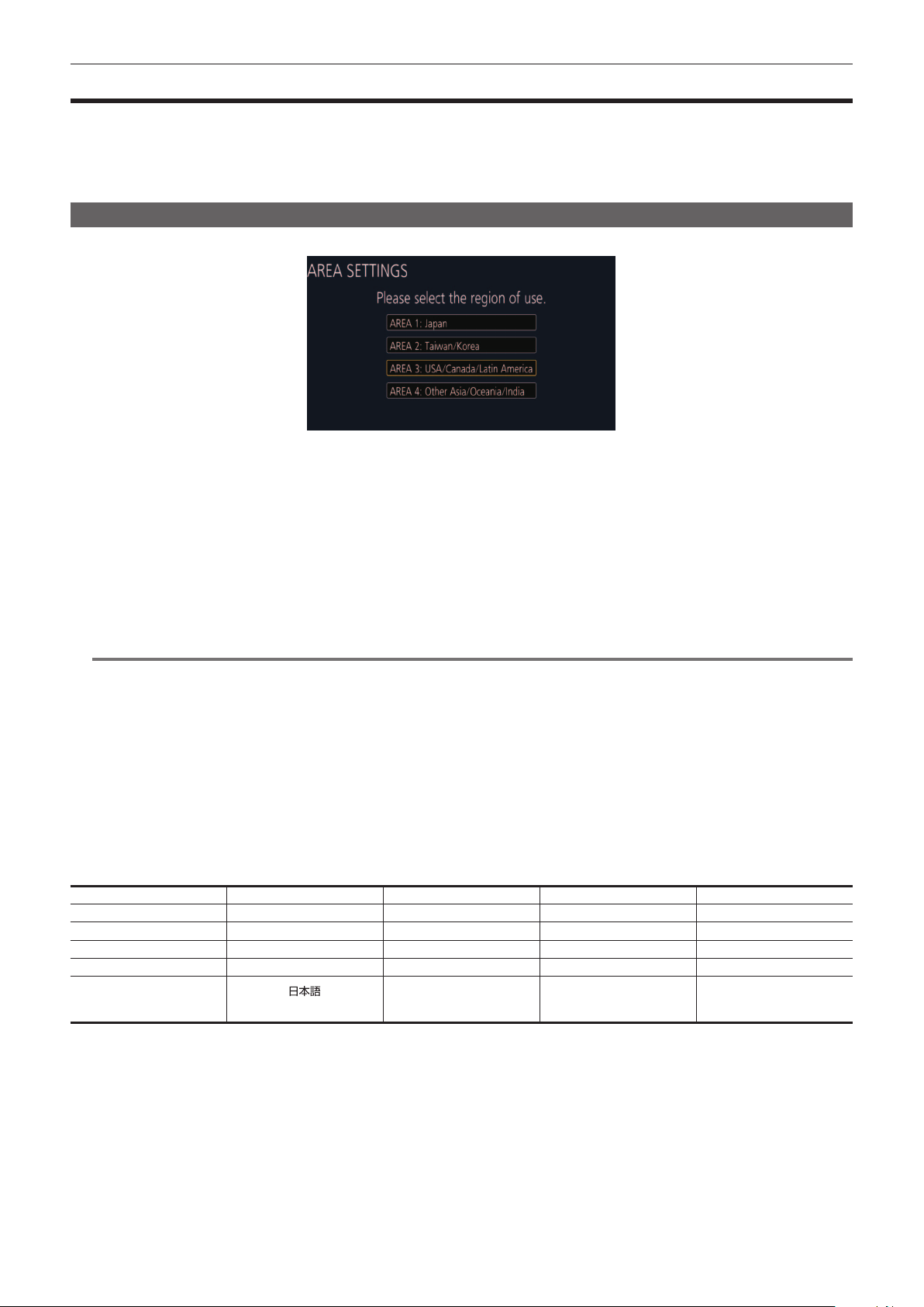
Chapter 1 Overview — When turning on the power for the rst time
When turning on the power for the rst time
The camera is shipped with the region of use not set.
[AREA SETTINGS] is displayed in the LCD monitor when the power is turned on for the rst time.
Follow the guidance and make the settings in the order of [AREA SETTINGS], [TIME ZONE], and then [CLOCK SETTING].
f There are two methods of operation: a method to operate with the multidial or the <%> button, <(> button, <)> button and <=/&> button, or a
method to touch the LCD monitor.
[AREA SETTINGS]
Set the region of use.
1
Connect the charged battery or the AC adaptor to the camera, and set the power switch to < j > (ON).
The [AREA SETTINGS] screen is displayed.
2
Select the region of use.
[AREA 1]: Japan
[AREA 2]: Taiwan, South Korea
[AREA 3]: United States of America, Canada, Central and South America regions
[AREA 4]: Asia region (excluding Japan, Taiwan, South Korea), Oceania region, India
3
When the confirmation message is displayed, select [YES].
The camera will be initialized in accordance to the region selected in Step 2. The camera will automatically restart.
Once the setting for [AREA SETTINGS] is completed, the [TIME ZONE] screen is displayed.
@
NOTE
t [AREA SETTINGS] is xed to [AREA 4] for AJ-UPX360ED.
[TIME ZONE] is displayed in the LCD monitor when the power is turned on for the rst time.
Follow the guidance and make the settings in the order of [TIME ZONE] and then [CLOCK SETTING].
t Once this is set, the [AREA SETTINGS] screen is not displayed from the next startup.
t To change the region of use, set with the [OPTION] menu → [AREA SETTINGS].
r Setting contents of each region of use
Following setting differs depending on the selected region.
f The [SYSTEM] menu → [FREQUENCY]
f The [SYSTEM] menu → [REC FORMAT]
f The [OTHERS] menu → [CLOCK] → [DATE FORMAT]
f The [AUDIO] menu → [REC CH SETTINGS] → [HEAD ROOM]
f The [OTHERS] menu → [LANGUAGE]
Item [AREA 1] [AREA 2] [AREA 3] [AREA 4]
[FREQUENCY] [59.94Hz] [59.94Hz] [59.94Hz] [50.00Hz]
[REC FORMAT] [1080-59.94i/422ALL-I 100M] [1080-59.94i/422ALL-I 100M] [1080-59.94i/422ALL-I 100M] [1080-50.00i/422ALL-I 100M]
[DATE FORMAT] [Y-M-D] [Y-M-D] [M-D-Y] [D-M-Y]
[HEAD ROOM] [20dB] [20dB] [20dB] [18dB]
[LANGUAGE]*
[
]
[English]
[English] [English]
[Español]
[Français]
[English]
[Español]
[Français]
* When [AREA 2] is selected, [LANGUAGE] is not displayed as the [OTHERS] menu item.
– 16 –
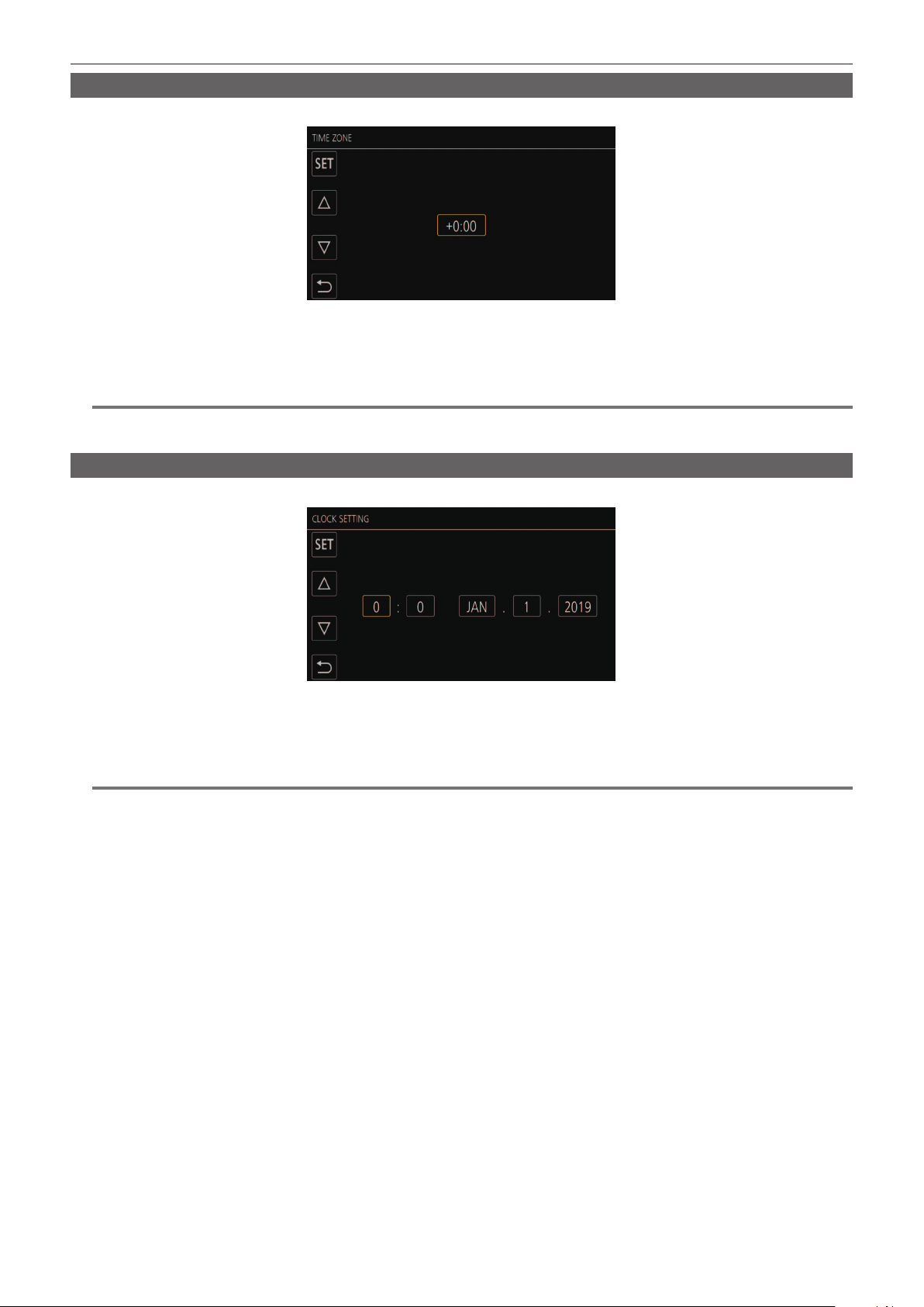
Chapter 1 Overview — When turning on the power for the rst time
[TIME ZONE]
Set the time difference from the Greenwich Mean Time.
1
Set the time difference.
2
Select [SET].
Once the setting for [TIME ZONE] is completed, the [CLOCK SETTING] screen is displayed.
@
NOTE
t The setting for the date/time of the camera changes together with the time zone settings.
t This can also be set with the [OTHERS] menu → [CLOCK] → [TIME ZONE].
[CLOCK SETTING]
Set the year, month, date, and time.
1
Set the year, month, date, and time.
2
Select [SET].
Once the setting is complete, the camera image screen is displayed on the LCD monitor.
@
NOTE
t This can also be set with the [OTHERS] menu → [CLOCK] → [CLOCK SETTING].

– 17 –
Chapter 1 Overview — Use of the camera on a system
Use of the camera on a system
Parts other than the camera are optionally available. Use the following recommended parts.
Basic conguration devices
Equipment necessary for shooting with the camera, such as batteries, etc.
Part name Part No. Remark
Super-directional electret stereo microphone
(phantom +48V)
AG-MC200G “Mounting the external microphone” (page 36)
Battery
AG-VBR59 (7.28 V, 5900 mAh, product compatible
to included battery)
AG-VBR89 (7.28 V, 8850 mAh)
AG-VBR118 (7.28 V, 11800 mAh)
VW-VBD58 (7.2 V, 5800 mAh)
“Attaching and removing the battery” (page 32)
Battery charger
AG-BRD50 (Product compatible to included battery
charger)
AG‑B23
“Charging the battery” (page 30)
Memory card* Visit the support desk at the website* “Preparing the memory card” (page 41)
* For the latest information not included in these Operating Instructions, refer to the support desk at the following website.
https://pro-av.panasonic.net/
Expanded conguration devices
In addition to the basic components, a wireless module can be used.
Part name Part No. Remark
Wireless module AJ-WM50 “For the wireless module” (page 176)
For details on wireless modules that can be connected, refer to the support desk at the following website.
https://pro-av.panasonic.net/
– 18 –
Chapter 1 Overview — What you can do with this camera
What you can do with this camera
This camera is an industrial 4K hand-held camera recorder equipped with a 1.0-inch sensor.
f Equipped with a high-sensitivity 1.0-inch MOS sensor for approximately 15.03 million effective pixels.
Achieves F12 (at 59.94 Hz)/F13 (at 50 Hz) in the high-sensitivity mode.
f The UHD (3840×2160) 59.94p/50p signal can be recorded to the memory card with high image quality and high efciency 10 quantizing bits.
f Equipped with wide angle 24.5 mm (35 mm conversion value), approximately 32x zoom using the I.ZOOM function (approximately 24x zoom when
recording in UHD), and hybrid optical image stabilizer (Hybrid O.I.S.).
f Equipped with a LAN terminal that supports live streaming and wired control (Gigabit Ethernet), in addition to the input/output terminals (XLR input/SDI
output) which are necessary for business use.
Recording to the memory card
Recording in following types is possible.
f P2 recording (P2 MXF compatible)
f UHD and FHD recording
(4:2:0 (10-bit) MOV recording (HEVC)/4:2:0 (8-bit) MOV recording/4:2:2 (10-bit) MOV recording)
f AVCHD recording
f Variable frame rate recording
(Supports 120fps/100fps shooting at the FHD resolution)
f Simultaneous recording
f Relay recording
f Interval recording
f Background recording
f Pre-recording
f 4ch audio recording
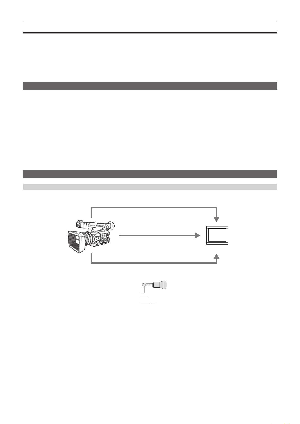
Linking to external devices
Connecting to monitor
A monitor can be connected to output images.
Video/audio cable
*
(<AV OUT> terminal)
HDMI cable
BNC cable (<SDI OUT> terminal)
Monitor
* Use a commercial video/audio cable (4-pole mini plug).
Check the wire specications of the 4-pole mini plug.
Audio (Left audio: White)
Video (Yellow)
Ground Audio (Right audio: Red)
f Use the double shielded cable supporting 4K/60P as the HDMI cable (optional). It is also recommended to use the Panasonic 4K/60P compatible
HDMI cable.
f For the BNC cable (optional) connected to the <SDI OUT> terminal, prepare a double-shielded cable equivalent to 5C-FB.
– 19 –
Chapter 1 Overview — What you can do with this camera
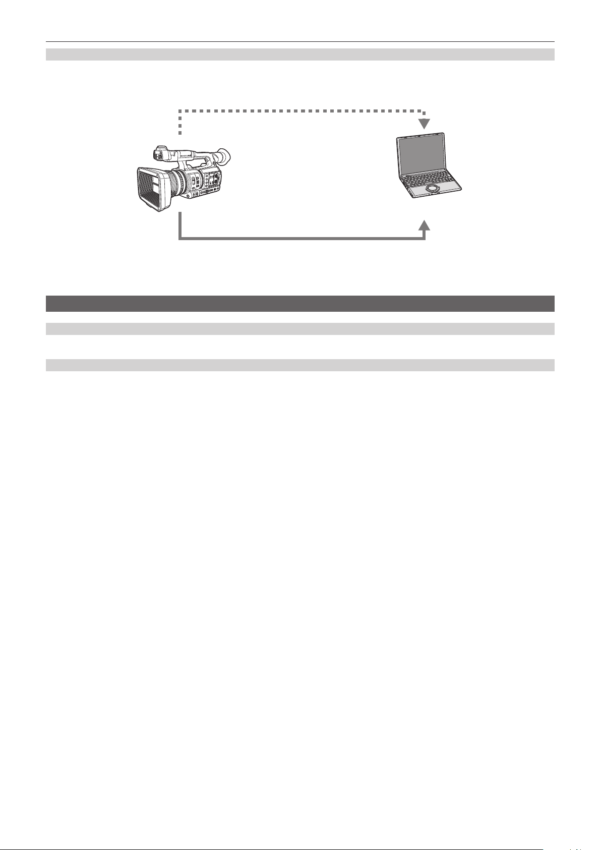
Card reader mode
Data (les) for performing nonlinear editing on a computer are transferred.
f The camera supports USB 3.1 (GEN1).
Memory card*
1
Computer
USB type C cable*
2
*1 Memory cards are optionally available. They are not supplied with the camera.
*2 A USB type C cable is not supplied with the camera.
Use a commercial USB-type C cable. Use of a cable no longer than 1.5 m is recommended.
The camera does not offer a bus-powered function.
Connecting to the network
Wired LAN connection
Streaming from the camera is possible by using the <LAN> terminal.
Wireless LAN connection
The camera can be connected to the wireless LAN by connecting a wireless module compatible to the camera to the <USB2.0 HOST> terminal of
camera.
The following operations can be performed from iPhone/iPad or Android terminal that has the CX ROP app installed.
f Checking camera status
f Camera remote control (focus, zoom, image quality settings, recording control such as start/end recording, and time code/user bits settings)
f Menu Operations
f Starting and stopping streaming (when the function is assigned to the USER button)
The camera supports the multi-camera function that a camera selected from up to eight cameras is controlled remotely from a single device.
For details of the wireless module supported by the camera and the operation of the CX ROP app, visit the support desk at the following website or refer
to the online help for the app.
https://pro-av.panasonic.net/

This chapter describes the names, functions, and operations of parts on the camera.
Chapter 2 Description of Parts
– 21 –
Chapter 2 Description of Parts — Camera
Camera
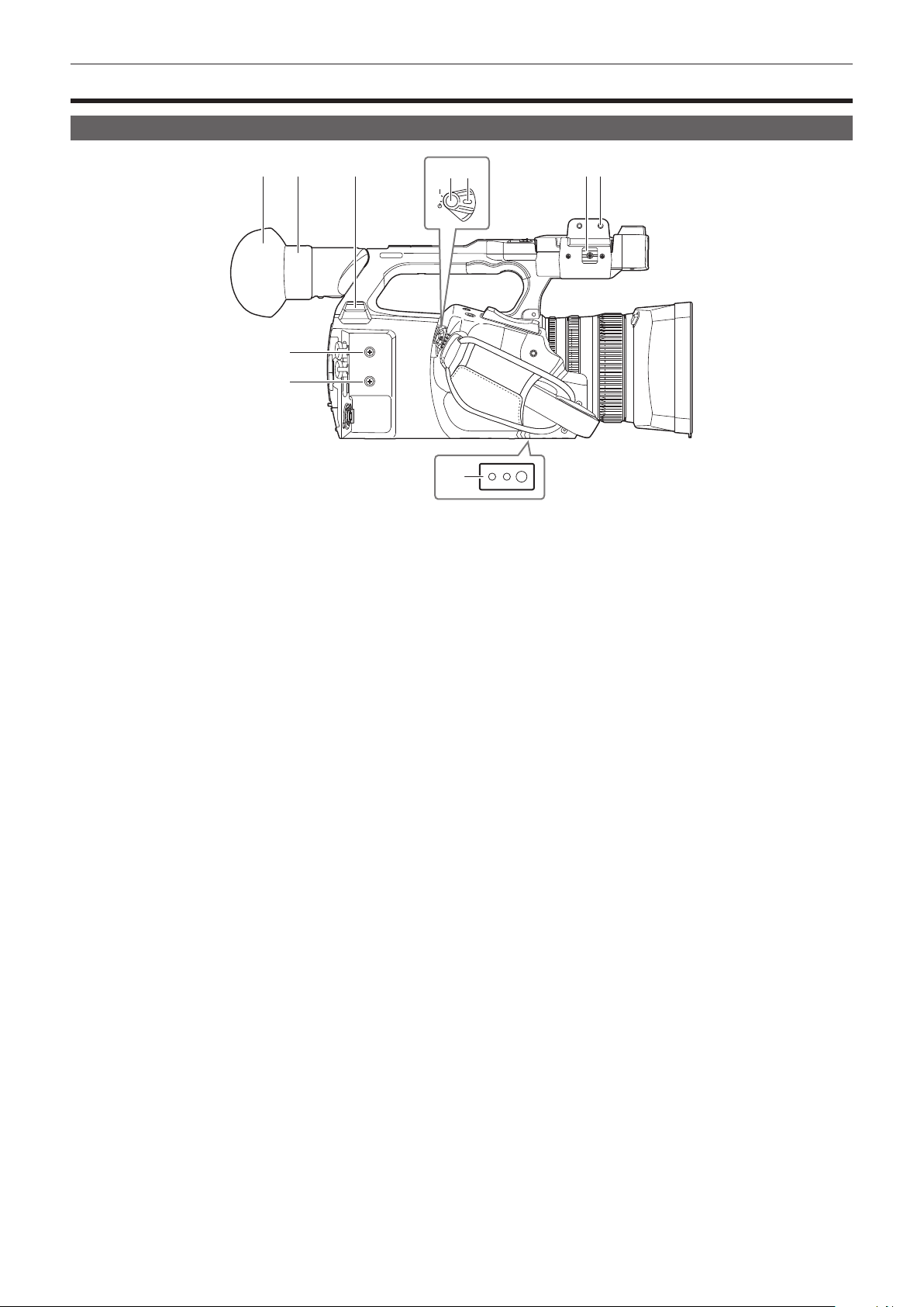
Left side
1 2 3 6 7
9
9
4 5
8
1 Eye cup
2 Eyepiece
Do not leave the eyepiece pointed toward the sun. Doing so might damage the devices inside.
3 <USB2.0 HOST> terminal
Can connect to wireless LAN when the wireless module (optional) compatible to camera is mounted.
4 REC button (on the grip)
Starts or stops the recording.
Used for direct shooting in thumbnail mode.
5 Power switch
Switches between power on/standby.
To turn on, set the power switch to < j > (ON). To set to standby, set the power switch to < h > (standby).
6 Microphone cable clamp
Fixes the external microphone cable.
7 Microphone holder mounting section
Mounts the supplied microphone holder with microphone holder screws.
8 Tripod holes
Attaches the tripod. (bottom)
f Mounting hole size
-1/4-20 UNC (screw length 5.5 mm or shorter)
-3/8-16 UNC (screw length 5.5 mm or shorter)
9 Accessory mounting holes
Attaches accessories.
The weight of the accessory should be no more than 2 k] including the mounting xture.
f Mounting hole size
-Mounting screw size: M3
-Mounting hole depth: 6 mm
-Mounting hole pitch: 25 mm
– 22 –
Chapter 2 Description of Parts — Camera
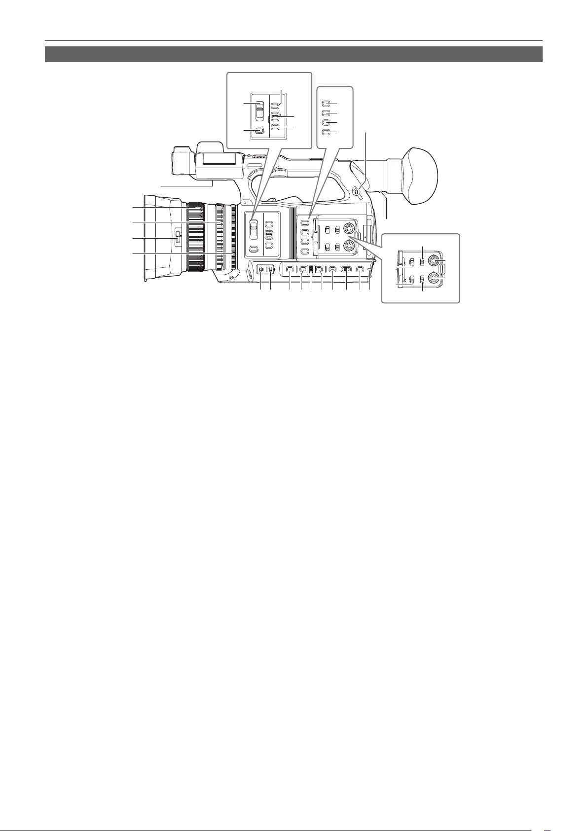
Right side
ND
FILTER
IRIS
FOCUS
FOCUS
ASSIST
1/64
A
M
∞
1/16
1/4
CLR
PUSH AUTO
INPUT 1
LINE
MIC
+48
V
LINE
MIC
+48
V
INT(L)
INPUT1
INPUT2
INT(R)
INPUT1
INPUT2
INPUT 2
CH1 CH 1
CH 2
SELECT
AUDIO
LEVEL
CH2
SELECT
O.I.S.
ZEBRA
1
2
3
4
WFM
A. IRIS LEVEL
6
7
1
2
3
4
22
20
21
18
19
23
24
25
26
8 9 10 12 14 15 16 17
32
5
29
30
27
28
31
11 13
1 Focus ring
Manually focuses when the <FOCUS> switch is set to <M>.
2 Zoom ring
Manually adjusts the zoom lens.
3 Lens cover switching lever
Opens/closes the lens cover.
4 Iris ring
Adjusts the lens iris manually when the manual iris is set with the <IRIS> button.
5 Diopter adjustment lever
Adjusts the diopter scale so that the viewnder screen can be viewed clearly.
6 Built-in speaker
Outputs audio during playback.
Audio is not output from the built-in speaker when headphones are connected to the headphone terminal.
7 Headphones terminal
Connects audio monitoring headphones.
8 <GAIN> switch
Switches the brightness of the screen according to the lighting conditions under which you are shooting.
9 <WHITE BAL> switch
Selects the method for adjustment of the white balance.
f <PRST>: Adjusts the white balance to the preset value. [3200K], [5600K], and [VAR] toggle each time the <AWB> button is pressed.
f <A>/<B>: Selects when using the stored value for the adjustment of the white balance.
10 <SHUTTER> button
Toggles the shutter mode.
11 <MENU> button
Displays the menu. Pressing the <MENU> button while the menu is displayed closes the menu.
Press the button while the thumbnail screen is displayed to display the operation screen of the thumbnail menu, and clips can be deleted.
12 Multidial
Moves, selects, and sets the menu while the menu is displayed.
Use the multidial to also operate thumbnails, select the multi manual function and select/set the various operation icons.
13 <EXIT> button
Returns to one level higher when the menu is displayed. Pressing the <EXIT> button without conrming the setting value will not reect the change
in the setting.
14 <DISP/MODE CHK> button
Displays/hides information other than the time counter, time stamp, zebra pattern, and marker.
Press and hold the button to display information about the settings of the various shooting functions and information such as a list of the functions
assigned to the USER button. Each press of the button toggles the information page in order.
15 <AUTO/MANUAL> switch
Selects the method to adjust the focus, gain, iris, white balance, and shutter speed at shooting. You can set the function to assign to <AUTO> in the
[CAMERA] menu → [AUTO SW].
<AUTO>: Adjusts automatically. (Auto mode)
<MANU>: Adjusts manually. (Manual mode)
16 <SLOT SEL> button/<USER 5> button
Selects the card slot to record to or play back from.
This is also used as the USER button (USER5).

– 23 –
Chapter 2 Description of Parts — Camera
17 Rear tally lamp
Illuminates when the recording is started. Flashes when the battery level becomes low.
Whether or not to illuminate the lamp can be set in the menu.
18 <ND FILTER> switch
Selects the ND lter to suit the illumination of the subject.
<CLR>: Does not use the ND lter.
<1/4>: Reduces the amount of light entering the MOS sensor to 1/4.
<1/16>: Reduces the amount of light entering the MOS sensor to 1/16.
<1/64>: Reduces the amount of light entering the MOS sensor to 1/64.
19 <IRIS> button
Selects the method for adjustment of the lens iris.
20 <FOCUS> switch
Select the focus function.
<A>: Changes to the auto focus mode. The auto focus mode adjusts the focus automatically.
<M>: Changes to the manual focus mode. Control the focus ring manually to adjust the focus.
<c>: Changes to the manual focus mode after the focus distance is set to innity.
The <FOCUS> switch is a spring switch. The switch returns to the <M> position even when pushed towards the <c> side.
21 <PUSH AUTO> button
Performs automatic focusing while pressing the button during manual focus mode.
22 <FOCUS ASSIST> button
Enables/disables the focus assist function which is set in the [VIDEO OUT/LCD/VF] menu → [FOCUS ASSIST] → [FOCUS ASSIST SW].
23 <O.I.S.>/<USER 1> button
Enables/disables the optical image stabilizer function.
This is also used as the USER button (USER1).
24 <ZEBRA>/<USER 2> button
Displays/hides zebra patterns.
This is also used as the USER button (USER2).
25 <WFM>/<USER 3> button
Displays/hides the waveform monitor displayed on the LCD monitor.
This is also used as the USER button (USER3).
26 <A.IRIS.LEVEL>/<USER 4> button
Enables/disables the auto iris level function.
Set the target value of the auto iris level in the [SCENE FILE] menu → [A.IRIS LEVEL EFFECT].
This is also used as the USER button (USER4).
27 <INPUT1> switch
Switches audio input signals connected to the <AUDIO INPUT 1> terminal.
<LINE>: Select when audio equipment is connected by the line input.
<MIC>: Select when the external microphone is connected.
<+48V>: Select when the external microphone is connected and the microphone needs a power supply.
28 <INPUT2> switch
Switches audio input signals connected to the <AUDIO INPUT 2> terminal.
<LINE>: Select when audio equipment is connected by the line input.
<MIC>: Select when the external microphone is connected.
<+48V>: Select when the external microphone is connected and the microphone needs a power supply.
29 <AUDIO LEVEL CH1> dial
Adjust the recording level of audio channel 1.
30 <AUDIO LEVEL CH2> dial
Adjust the recording level of audio channel 2.
31 <CH1 SELECT> switch
Selects the audio to be recorded on audio channel 1.
<INT(L)>: Records the left audio of the built-in microphone.
<INPUT1>: Records input signals from the <AUDIO INPUT 1> terminal.
<INPUT2>: Records input signals from the <AUDIO INPUT 2> terminal.
32 <CH2 SELECT> switch
Selects the audio to be recorded on audio channel 2.
<INT(R)>: Records the right audio of the built-in microphone.
<INPUT1>: Records input signals from the <AUDIO INPUT 1> terminal.
<INPUT2>: Records input signals from the <AUDIO INPUT 2> terminal.
– 24 –
Chapter 2 Description of Parts — Camera
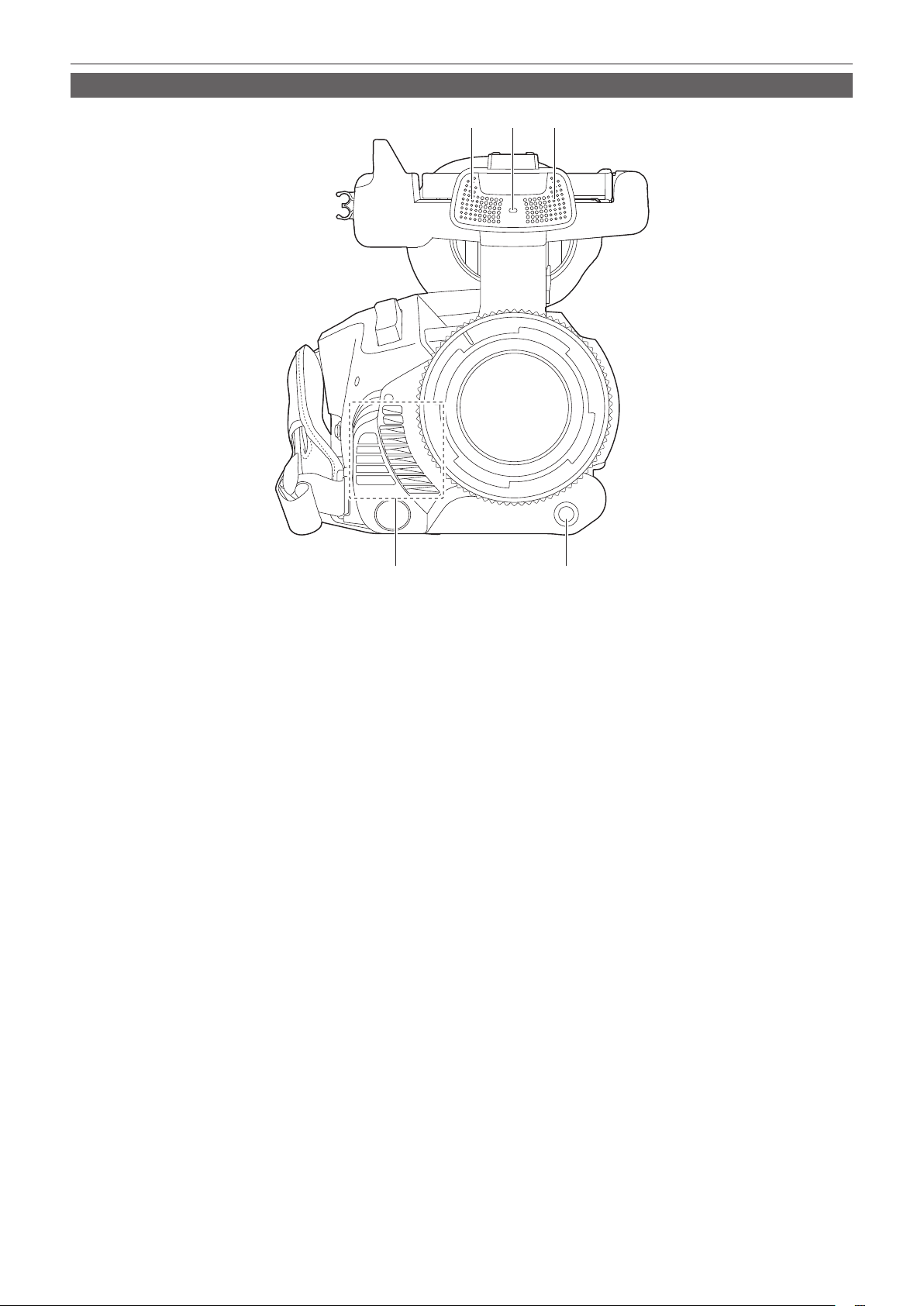
Front side
1 12
4
3
1 Built-in microphone
This is the built-in stereo microphone <L>/<R>.
2 Front tally lamp
Illuminates when the recording is started. Flashes when the battery level becomes low.
Whether or not to illuminate the lamp can be set in the menu.
3 Fan outlet
Fan outlet for cooling fan. Do not block this while the camera is being used.
4 <AWB>/<USER 7> button
Adjusts the white balance. Press it for two seconds or more to adjust the white balance and then black balance.
This is also used as the USER button (USER7).
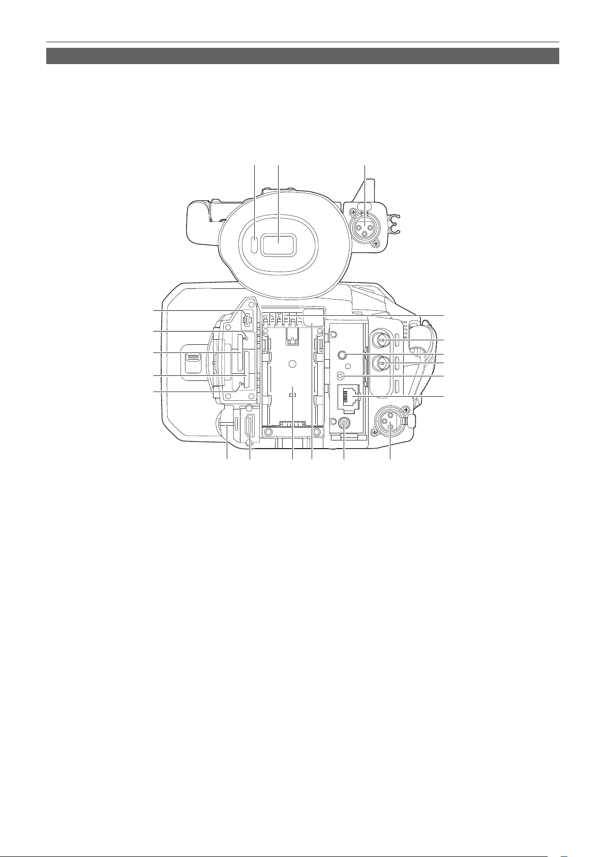
– 25 –
Chapter 2 Description of Parts — Camera
Rear side
Following terminals, card slots, and card access lamps are inside each cover.
f <USB3.0 DEVICE> terminal
f <AV OUT> terminal
f <REMOTE> terminal
f <LAN> terminal
f <HDMI> terminal
f <DC IN 12V> terminal
12 13 14
6
7
8
9
10
11
15 16 17 18 19 20
5
2
3
4
1
1 <USB3.0 DEVICE> terminal
Connect to a computer with the USB type C cable to transfer data.
2 Card 1 access lamp
Indicates the access status for recording and playback of the memory card inserted in card slot 1.
Whether or not to illuminate the lamp can be set in the menu.
3 Card slot 1
A slot for the memory card.
4 Card slot 2
A slot for the memory card.
5 Card 2 access lamp
Indicates the access status for recording and playback of the memory card inserted in card slot 2.
Whether or not to illuminate the lamp can be set in the menu.
6 Fan inlet
Fan inlet for cooling fan. Do not block this while the camera is being used.
7 <SDI OUT> terminal
A terminal to output SDI signal by connecting a monitor, etc.
8 <AV OUT> terminal
This is the output terminal for the video and audio of an external monitor.
9 <TC IN/OUT> terminal
Connects to an external equipment and output/input a time code.
Inputs the standard time code when locking the time code with an external equipment.
Input and output are set in the [RECORDING] menu → [TC/UB] → [TC IN/OUT SEL].
10 <REMOTE> terminal
Connects the remote control unit (optional) to control some functions remotely.
11 <LAN> terminal
Connects the LAN cable.
12 Eye sensor
Screen is displayed on the viewnder when an eye is brought close.
13 Viewnder
– 26 –
Chapter 2 Description of Parts — Camera
14 <AUDIO INPUT 1> terminal (XLR, 3-pin)
Connects an audio equipment or an external microphone.
15 Rear tally lamp
Illuminates when the recording is started. Flashes when the battery level becomes low.
Whether or not to illuminate the lamp can be set in the menu.
16 <HDMI> terminal
A terminal to output video signal by connecting a monitor, etc.
17 Battery mounting section
Mounts a battery.
18 Battery release button
Used when removing the battery from the camera.
19 <DC IN 12V> terminal
Connects the supplied AC adaptor and supplies an external power.
20 <AUDIO INPUT 2> terminal (XLR, 3-pin)
Connects an audio equipment or an external microphone.
Top side
1
13
12
14
2 3 4 5
19
6
7
1110987
21 22 23
16
17
18
20
15
1 LCD monitor
2 Light shoe
Attaches the video light, etc.
3 REC button (on the handle)
Starts or stops the recording.
This includes hold mechanism.
4 Zoom lever (on the grip)
Adjusts the zoom of an image.
<T>: Zooms in the image.
<W>: Zooms out the image.
5 <IRIS>/<USER 6> button
Selects the method for adjustment of the lens iris.
This is also used as the USER button (USER6).
6 <REC CHECK> button
Press this button while recording is suspended to play back the last three seconds of video or audio of the clip that was just shot.
7 Shoulder strap mounting section
Mounts the supplied shoulder strap. (page 34)
8 Zoom lever (on the handle)
Adjust the zoom of an image.
<T>: Zooms in the image.
<W>: Zooms out the image.
9 Focal plane index <
>
Indicates the focal plane of the MOS sensor. It provides a reference for measuring the accurate focal distance from the subject.
10 Handle mounting holes
Mounts the handle.
f Mounting hole size
-1/4-20 UNC (screw length 5.5 mm or shorter)
11 Accessory shoe
Attaches the video light.

– 27 –
Chapter 2 Description of Parts — Camera
12 <THUMBNAIL> button
Press this button to display the thumbnail screen on the LCD monitor and viewnder. Press it again to return to the regular display.
13 <COUNTER> button
Switches the display item of the counter.
14 <RESET> button
Resets the time counter or clears the input value in the keyboard screen.
15 <MENU> button
Displays the menu. Pressing the <MENU> button while the menu is displayed closes the menu. Press it while the thumbnail is displayed to display
the operation screen of the thumbnail menu, and clips can be deleted.
16 <AUDIO MON/ADV> button
Adjusts the volume of the monitor audio during playback, recording, and recording standby.
<+>: Increases the volume of the monitor audio. When pressing during pause, frame-by-frame play is performed.
<−>: Decreases the volume of the monitor audio. When pressing during pause, frame-by-frame rewind is performed.
17 <SET> button
Performs operations of the settings menu and thumbnails.
18 <)> button
Performs operations of the settings menu and thumbnails.
Press this button during playback to perform fast-forward playback.
Press this button while playback is paused to skip to the beginning of the next clip.
19 <=/&> button
Performs operations of the settings menu and thumbnails.
Press this button to view playback images.
Press this button during playback to pause playback.
Press this button to resume playback during a pause, fast-forward playback, or fast-reverse playback.
20 <%> button
Performs operations of the settings menu and thumbnails.
Press this button during playback to fast-reverse playback.
Press this button while playback is paused to skip to the beginning of the clip.
21 <(> button
Performs operations of the settings menu and thumbnails.
Press this button to stop playback when a clip is playing.
22 <EXIT> button
Returns to one level higher when the menu is displayed. Pressing the <EXIT> button without conrming the setting value will not reect the change
in the setting.
23 <BARS> button
Switches on/off the color bar. The color bar is interlocked with the test tone (1 kHz).
– 28 –
Chapter 2 Description of Parts — Basic operation
Basic operation
Multidial operation
Operate the multidial on the camera by turning it in vertical direction or pushing it.
f Turning the multidial in vertical direction will move the cursor.
The cursor can also be moved by pressing the <%> button, <(> button, <)> button, and <=/&> button.
f Pressing the multidial will select or conrm the item with cursor.
Selection and conrmation are also available by pressing the <SET> button.
f Values of the menu or the pages of the thumbnail screen can be changed continuously by pressing and turning the multidial vertically to x the setting.
Values of the menu or the pages of the thumbnail screen can be changed continuously even by pressing and holding the <%> button, <(> button,
<)> button, and <=/&> button.
@
NOTE
t For details about operating the menu, refer to “When operating with the multidial” (page 63).
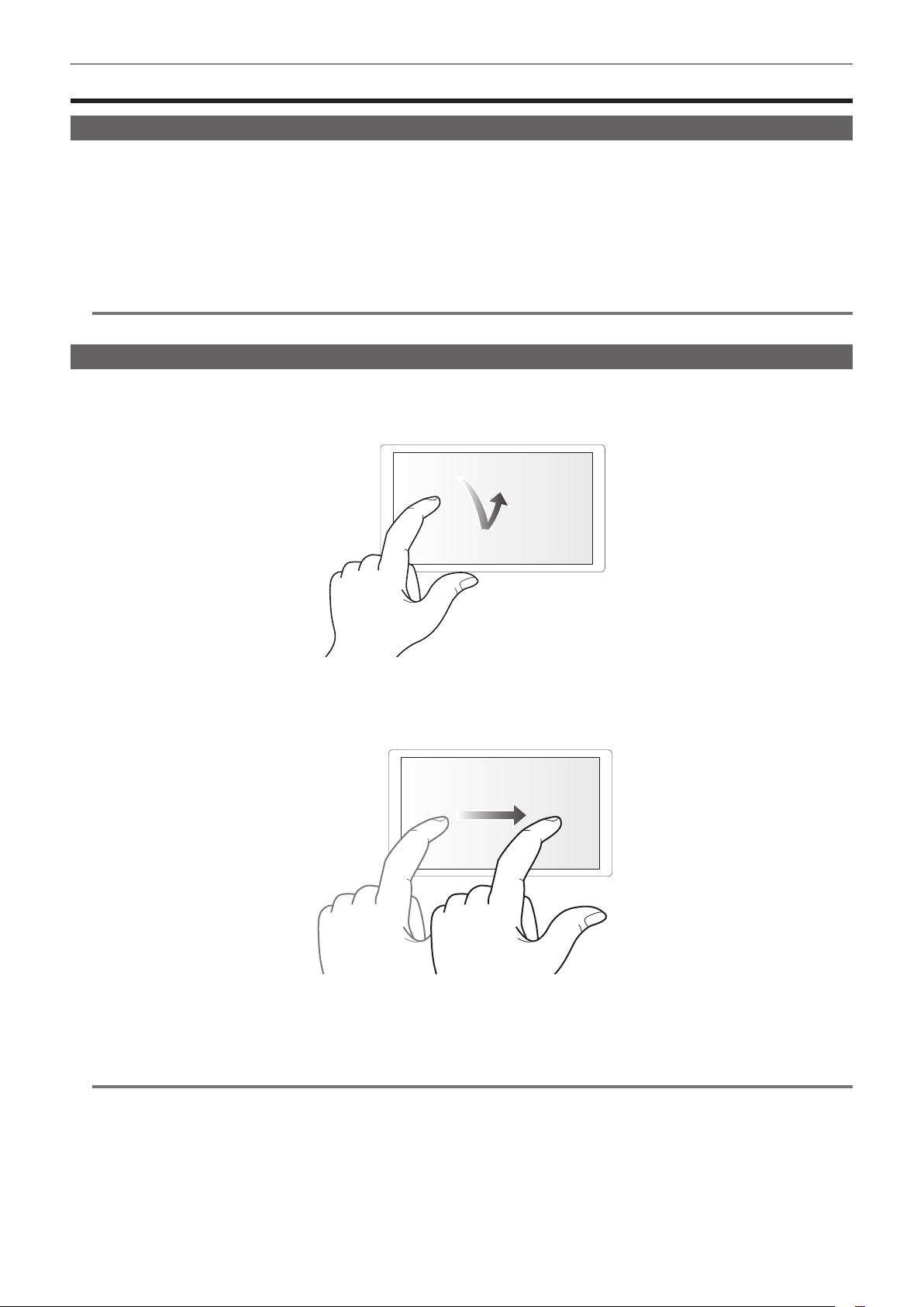
Touch operation of the LCD monitor
The LCD monitor can be operated by directly touching with a nger.
Do not touch the LCD monitor with a pointed hard object such as a ball point pen.
r Touching
An operation to press and release the LCD monitor. An item or icon can be selected, or an item can be executed.
f To select an icon, touch the center of the icon.
f It will not operate while touching a different location of the LCD monitor.
r Sliding
An operation to move a nger while touching the LCD monitor. Playback operation such as the skip playback or direct playback, etc. can be performed.
r Touching and holding
An operation to keep on pressing, then releasing the LCD monitor. Values of the menu or the pages of the thumbnail screen can be changed
continuously.
@
NOTE
t For details about operating the menu, refer to “When operating by touching the LCD monitor” (page 64).

Before you use the camera, mount the battery following the procedures in this chapter. The mounting of accessories is also described in this chapter.
Chapter 3 Preparation
– 30 –
Chapter 3 Preparation — Power supply
Power supply
A battery or the supplied AC adaptor can be used as the power supply for the camera.
f The camera is compatible to following batteries. (As of October 2019)
-AG-VBR59 (supplied/optional, supports quick charging)
-AG-VBR89 (optional, supports quick charging)
-AG-VBR118 (optional, supports quick charging)
-VW-VBD58 (optional)
Charging the battery
The battery is not charged at the time of purchase. Fully charge the battery in the battery charger before using the battery.
It is recommended that you have one extra battery.
f It is recommended to perform charging of the batter in a location with ambient temperature of 10 °C to 30 °C (same for the battery temperature).
f The supplied AC cable is dedicated for this camera. Do not use with any other device. Also, do not use AC cable from other device on this camera.
f The supplied battery charger can simultaneously charge two batteries. Also, it is compatible with the quick charge battery.
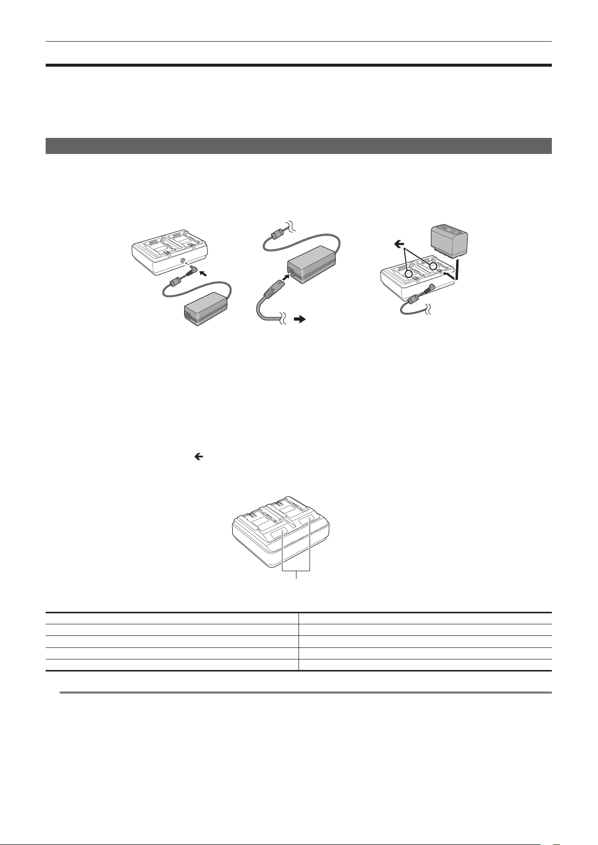
Fig. 1 Fig. 2 Fig. 3
To the power outlet
1
Connect the DC plug of the AC adaptor to the <DC IN 12V> terminal of the battery charger. (Fig. 1)
2
Connect the AC cable to the AC adaptor. (Fig. 2)
f Insert the AC cable all the way in until it stops.
3
Connect the power plug to the power outlet. (Fig. 2)
4
Mount the battery to the battery charger. (Fig. 3)
The charging lamp of the side the mounted battery will illuminate, and the charging will start.
f Place the battery horizontally along the
mark, and slide it.
f Once the charging is completed, the <CHARGE1>/<CHARGE2> lamp (charging lamp) will turn off. Slide the battery and remove it.
r Display of the <CHARGE1>/<CHARGE2> lamp
<CHARGE1>/<CHARGE2> lamp
The <CHARGE1>/<CHARGE2> lamp (charging lamp) of the supplied battery charger indicates the charging status as follows.
Display of the <CHARGE1>/<CHARGE2> lamp Charging status
Green (illuminated) Quick charging
Orange (illuminated) Normal charging
Orange (ashing) Stopped charging due to an error
Off Charging is completed or the battery is not mounted
@
NOTE
t The battery charger will determine the status of the battery after the battery is mounted. Therefore, it may take some time until the charging lamp is to
illuminate. Mount the battery again if the charging lamp does not illuminate after ten seconds or longer has elapsed.
t When two quick charging compatible batteries are mounted, the quick charging on the <CHARGE1> side will take priority, and the charging on the
<CHARGE2> side will be normal charging. Once the charging of the <CHARGE1> side proceeds, the charging on the <CHARGE2> side will switch to
quick charging.
Also, depending on the charging status of the battery, the indicator on the battery that is mounted on the <CHARGE2> side may turn off.
t The battery charger will perform optimal charging after determining the status of the battery. Once the charging is started, the indicator for quick
charging compatible battery will ash. Also, if it is charging on both <CHARGE1> side and <CHARGE2> side, charging of both batteries will stop when
either one of the battery is mounted/removed, or replaced. It will start the charging again after determining the status of the batteries.
t Mount the battery to be charged prioritized on the <CHARGE1> side when charging.
– 31 –
Chapter 3 Preparation — Power supply
Standard charging time and recordable time
Battery parts number Voltage/capacity (minimum) Charging time Continuous recordable time
AG-VBR59 (supplied/optional) 7.28 V/5900 mAh Approx. 3 hours 20 minutes Approx. 3 hours 20 minutes
AG-VBR89 (optional) 7.28 V/8850 mAh Approx. 4 hours Approx. 5 hours
AG-VBR118 (optional) 7.28 V/11800 mAh Approx. 4 hours 40 minutes Approx. 6 hours 40 minutes
VW-VBD58 (optional) 7.2 V/5800 mAh Approx. 5 hours 20 minutes Approx. 3 hours 10 minutes
f The charging time is the time when charged using the supplied battery charger.
f The charging time is the time when the operating ambient temperature is 25 °C and operating relative humidity is 60%. At other temperature and
humidity the charging time may take longer.
f The charging time is the time to charge when the charging capacity of the battery is used up. The charging time or the continuous recordable time
differs depending on the use condition such as high or low temperature.
f Continuous recordable time is the time when the camera is used fullling all of the following conditions. If you use the camera in other conditions,
continuous recordable time will shorten.
-When the menu settings as the factory settings (when [REC FORMAT] is set to [1080-59.94i/422ALL-I 100M]/[1080-50.00i/422ALL-I 100M]) is set
-When the LCD monitor is used and cable is not connected to the external input/output terminal
@
NOTE
t Battery is warm after using or after charging, but this is not a malfunction.
t The battery can be charged with the battery charger AG-B23 (DE-A88) (optional), but it will take longer to charge.
Checking the remaining battery level
The remaining battery level can be checked with the power status display on the LCD monitor or the indicator on the supplied battery.
Checking the remaining battery level with the LCD monitor
The battery status display will change as
→ → → → → while the remaining battery level gets lower. It will ash in red when
the remaining battery level is zero.
@
NOTE
t The power status display may not be displayed depending on the setting in the menu.
t Repair or copy of the clip, or update of the rmware is not possible when it is ashing in red.
Checking the remaining battery level with the battery
f The remaining battery level can be checked with the indicator display by pressing the <CHECK> button on the battery when it is not charging.
-The remaining battery level is a rough indication.
-The indicator will not illuminate even if the <CHECK> button is pressed when the remaining battery level is zero. Charge the battery.
f The progress of the charging is notied by the ashing position of the indicator while the battery is charging.
Once the charging is completed, the indicator turns off.
CHECK
100
%
0
1 2
1 Indicator
2 <CHECK> button
r Display of the indicator
f The color and illuminate/ashing status of the indicator indicated by the icon in the table are as follows.
-
: Flashing in green
-
: Illuminated in green
-
: Off
Indicator display
Remaining battery level/charging progress
When checking the remaining battery level Charging
0% - 25%
25% - 50%
50% - 75%
75% - 100%
f Display of the indicator is a rough indication. If the battery is mounted to the camera or the battery charger, check the remaining level on the device the
battery is mounted to. The remaining level may differ from the one displayed with the indicator on the battery.
– 32 –
Chapter 3 Preparation — Power supply
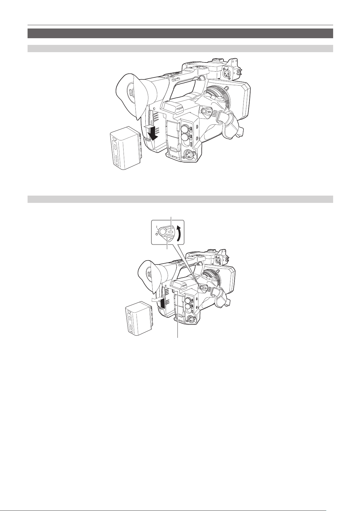
Attaching and removing the battery
Attaching the battery
1
Press the battery against the battery mounting section of the camera, and mount it by sliding it downward.
f Press in the battery until it clicks and gets locked.
Removing the battery
Battery release button
Lock release button
Power switch
1
Align the power switch to < h > (standby) while holding down the lock release button.
Make sure that the LCD monitor has gone off.
2
While pressing the battery release button on the camera, slide the battery upward and remove it.

– 33 –
Chapter 3 Preparation — Power supply
Using the AC adaptor
Attaching the AC adaptor
Use the supplied AC adaptor. Do not use an AC adaptor for other device.
The supplied AC cable is dedicated for this camera. Do not use with any other device. Also, do not use AC cable from other device on this camera.
Fig. 1 Fig. 2
To the power outlet
1
Connect the AC cable to the AC adaptor. (Fig. 1)
f Insert the AC cable all the way in until it stops.
2
Connect the power plug to the power outlet. (Fig. 1)
3
Connect the AC adaptor to the <DC IN 12V> terminal. (Fig. 2)
f When removing the AC adaptor, always set the power switch to < h > (standby), and check that the LCD monitor is turned off before removing.
@
NOTE
t To record with the AC adaptor connected, mount the battery in case there is a power outage or disconnection of the power outlet.
t The power is consumed even when the power switch is set to < h > (standby). To prevent power consumption, disconnect the AC adaptor from the
power outlet when it is not used for a long period of time.
t The battery charger and the AC adaptor is designed to operate regardless of the country or region in use. This operates with power supply voltage of
100 V-240 V, and power supply frequency of 50 Hz or 60 Hz. However, the shape of the power outlet differs depending on the country or the region.
Prepare a plug that ts the shape of the power outlet. Consult the dealer for conversion plug.
– 34 –
Chapter 3 Preparation — Mounting accessories
Mounting accessories
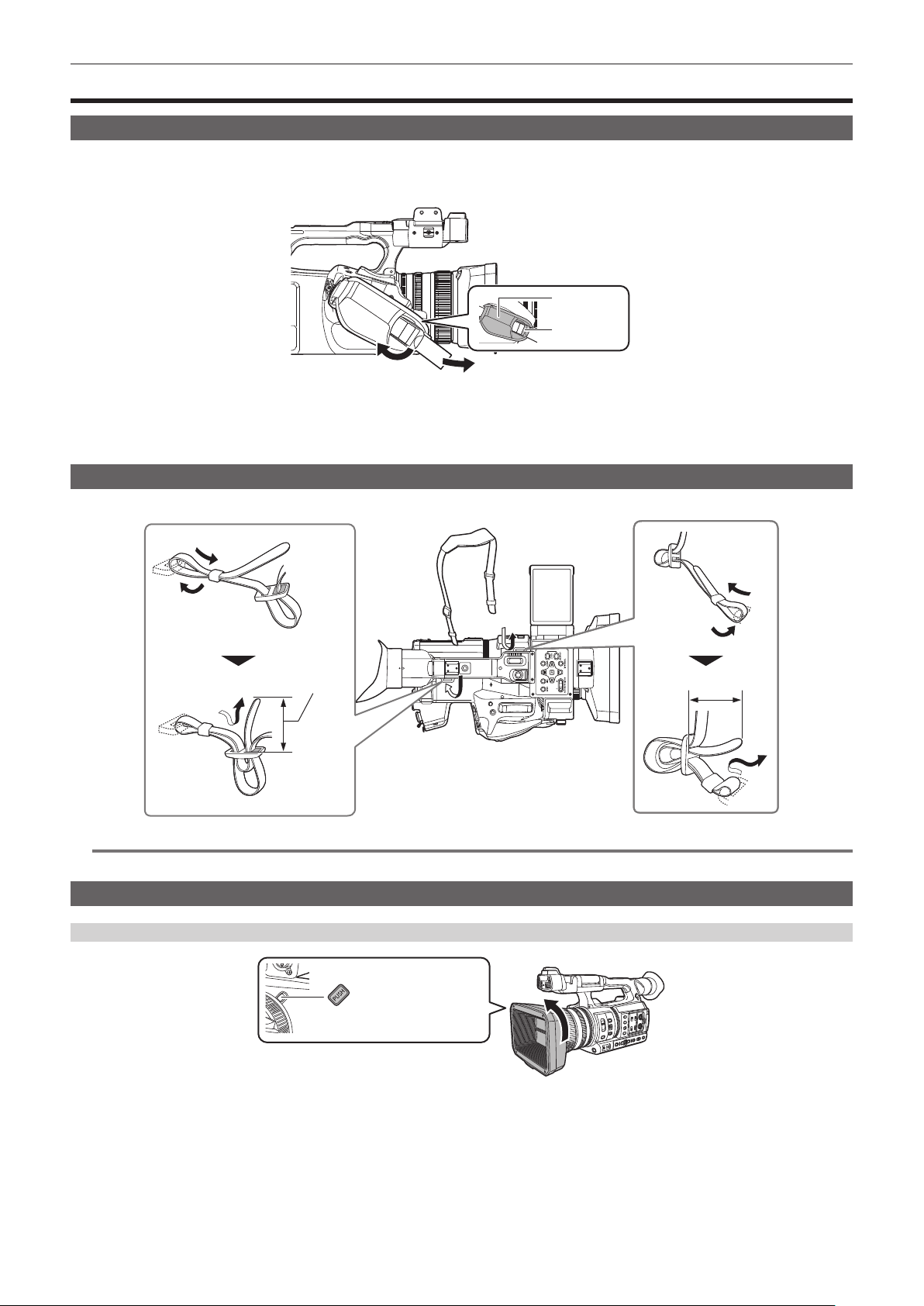
Adjusting the grip belt
f Adjust the grip belt so that it ts the size of your hand.
f The grip belt is already mounted to the camera.
f If the buckle is difcult to tighten, move the pad forward and tighten the buckle again.
1
2
Pad
Buckle
1
Open the buckle section.
2
Pull the end of the belt.
Attaching the shoulder strap
Mount the supplied shoulder strap to the shoulder strap mounting section.
20 mm or more
20 mm or more
@
NOTE
t Make sure that the shoulder strap is securely attached.
Mounting the lens hood
Removing
Lens hood release button
1
While pressing the lens hood release button, turn the lens hood in the direction of the arrow to remove it.
– 35 –
Chapter 3 Preparation — Mounting accessories
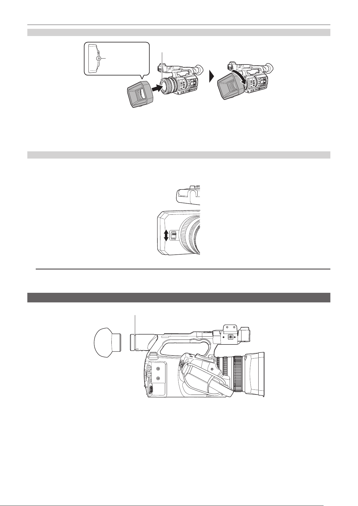
Mounting
Mounting mark
Mounting mark
1
Insert the lens hood into the camera.
f Align the mounting marks on the lens hood and camera.
2
Turn the lens hood clockwise.
f Turn until the lens clicks and locks into place.
Opening and closing the lens cover
Use the lens cover open/close lever to open and close the lens cover.
Open the lens cover when shooting.
When not using the camera, close the lens cover in order to protect the lens.
@
NOTE
t Do not press the lens cover with force. Doing so may damage the lens and lens cover.
t The lens cover may not open and close or the lens hood may not mount depending on the various lters and MC protectors mounted to the front lens
of the camera.
Mounting the eye cup
Groove
1
Attach the eye cup by aligning the groove on the attaching part of the eye cup with the inner ridge of the eye cup.
– 36 –
Chapter 3 Preparation — Mounting accessories
Mounting the external microphone
External microphone such as the super-directional microphone AG-MC200G (optional) can be mounted onto the handle.
Screws are attached on the camera body in advance to protect the screw holes. Remove those screws when you attach the microphone holder.
f The microphone holder cannot be mounted with the screws originally attached to the camera. Use the supplied microphone holder screws.
Microphone holder
Microphone cable clamp
<AUDIO INPUT 1> terminal
Fig. 3Fig. 2Fig. 1
Microphone holder screws
1
Mount the supplied microphone holder to the microphone holder mounting section using the microphone holder screws (x 2).
(Fig. 1)
2
Mount the external microphone and tighten the microphone holder screws. (Fig. 2)
3
Connect the microphone cable to the <AUDIO INPUT 1> terminal. (Fig. 3)
4
Attach the microphone cable to the microphone cable clamp.
Toggle the <INPUT1> switch to match the microphone to be connected.
@
NOTE
t Remove the microphone cable from the <AUDIO INPUT 1> terminal while pushing the lever.
Attaching a tripod
The tripod attachment holes accept 1/4-20 UNC and 3/8-16 UNC screws. Use the hole that matches the diameter of the clamping screw on the tripod.
@
NOTE
t Use a tripod in safe locations.
t The depth of the tripod attachment hole is 5.5 mm. Do not over-tighten the tripod screw when mounting the camera to a tripod.

– 37 –
Chapter 3 Preparation — Mounting accessories
Mounting accessories
You can mount and use equipment you have.
Accessory mounting holes
f The mounting screw size is M3.
f The mounting hole depth is 6 mm.
Do not over-tighten the screws when mounting accessories to the camera.

– 38 –
Chapter 3 Preparation — Turning on/off the power
Turning on/off the power
Lock release button
Power switch
How to turn on the power
1
Align the power switch to < j > (ON) while holding down the lock release button.
The LCD monitor lights up.
f The [AREA SETTINGS] screen is displayed when the power is turned on for the rst time.
Set the region of use, date, time, and time zone.
f The [TIME ZONE] screen and then the [CLOCK SETTING] screen are displayed sequentially when the power of AJ-UPX360ED is turned on for the
rst time.
Set the time zone, date, and time.
@
NOTE
t The built-in battery (rechargeable battery) will discharge. The setting for date/time may be initialized when the camera is not turned on for
approximately four months.
Set the date/time again after charging the built-in battery. (page 39)
How to turn off the power
1
Align the power switch to < h > (standby) while holding down the lock release button.
The LCD monitor goes off.

– 39 –
Chapter 3 Preparation — Charging the built-in battery
Charging the built-in battery
The date/time set in the camera is maintained by the built-in battery.
The built-in battery has been exhausted if [BACKUP BATT EMPTY] is displayed in the viewnder or LCD monitor for approximately ve seconds when
the power of the camera has not been turned on for a while, and then the power switch is set to < j > (ON).
The date of the internal clock of the camera resets to January 1, 2019 if the built-in battery is exhausted.
Charge the built-in battery with the following procedure.
1
Set the power switch to < h > (standby).
2
Connect a fully charged battery or the AC adaptor to the camera.
For details about the connection of the battery or AC adaptor, refer to “Power supply” (page 30).
3
Leave the camera for approximately 24 hours.
The built-in battery will be charged.
The built-in battery is charged even when the power switch is set to < j > (ON).
Check the date/time setting and the time code after charging. If [INTERNAL CLOCK HAS RESET] [<PLEASE SET TO CORRECT TIME>] is
displayed on the STATUS screen of the mode check, set the date/time of the internal clock. (page 40)
4
Set the power switch to < j > (ON), and check that [BACKUP BATT EMPTY] is not displayed in the LCD monitor.
If [BACKUP BATT EMPTY] is still displayed after charging, the built-in battery needs to be replaced. Consult your dealer.

– 40 –
Chapter 3 Preparation — Setting the date/time of the internal clock
Setting the date/time of the internal clock
The date/time/time zone are recorded as meta data in the clip while shooting.
This will affect the management of recorded clips, so always check and set the date/time and time zone before using the camera for the rst time.
Do not change the setting of the date/time and time zone while shooting.
1
Press the <MENU> button.
The menu is displayed.
2
Select the [OTHERS] menu → [CLOCK] → [TIME ZONE], and set the time difference from Greenwich Mean Time.
3
Select the [OTHERS] menu → [CLOCK] → [CLOCK SETTING], and set the year, month, date, and time.
@
NOTE
t Accuracy of the clock is approximately ±30 seconds per month. Check and reset the time when accurate time is required.
t In the AVCHD format, clip will be save in +12:30 even selecting +12:45 due to format standards.
r Time zone table
Time difference Region Time difference Region
00:00 Greenwich
+01:00
Central Europe
−00:30 +01:30
−01:00
Azores
+02:00
Eastern Europe
−01:30 +02:30
−02:00
Mid‑Atlantic
+03:00
Moscow
−02:30 +03:30
Tehran
−03:00
Buenos Aires
+04:00
Abu Dhabi
−03:30
Newfoundland
+04:30
Kabul
−04:00
Halifax
+05:00
Islamabad
−04:30
Caracas
+05:30
Mumbai
−05:00
New York
+06:00
Dakar
−05:30 +06:30
Yangon
−06:00
Chicago
+07:00
Bangkok
−06:30 +07:30
−07:00
Denver
+08:00
Beijing
−07:30 +08:30
−08:00
Los Angeles
+09:00
Tokyo
−08:30 +09:30
Darwin
−09:00
Alaska
+10:00
Guam
−09:30
Marquesas Islands
+10:30
Lord Howe Island
−10:00
Hawaii
+11:00
Solomon Islands
−10:30 +11:30
−11:00
Midway Islands
+12:00
New Zealand
−11:30 +12:45
Chatham Islands
−12:00
Kwajalein Atoll
+13:00
Phoenix Islands
+00:30
– 41 –
Chapter 3 Preparation — Preparing the memory card
Preparing the memory card
Memory cards supported by the camera
The following SD cards and microP2 cards can be used with the camera. (As of October 2019)
Type of the SD card Recording capacity
SDHC memory card 4 GB - 32 GB
SDXC memory card 48 GB - 128 GB
Type of the microP2 card Recording capacity
microP2 card A series 32 GB, 64 GB
microP2 card B series 64 GB
f Operation is not guaranteed for any memory cards other than the above.
f Panasonic memory cards are recommended.
f The following memory cards cannot be used because they do not comply with the SD standards.
-A memory card with 4 GB or more without the SDHC logo
-A memory card with 48 GB or more without the SDXC logo
f The camera does not support the CPS (Content Protection System) function of the microP2 card, so a microP2 card formatted with encryption with
CPS password cannot be sued. When formatted with the camera, it can be used as a microP2 card that is not encrypted.
Speed Class during shooting
The memory card to use differs depending on the recording mode and the recording format.
Use memory cards compatible with the Speed Class, UHS Speed Class, or Video Speed Class.
The recording may stop suddenly when a memory card not compatible with the required Speed Class is used.
f Speed Class, UHS Speed Class, and Video Speed Class are the speed specication regarding continuous writing. Check the display on the label and
other information on the memory card.
r When the recording mode is P2
microP2 cards can be used.
Recording bit rate or recording function Speed Class Example of card display
All microP2 card A series, microP2 card B series
r When the recording mode is MOV
SDXC memory cards and 64 GB microP2 cards can be used.
SDHC memory cards and 32 GB microP2 cards cannot be used.
Recording bit rate or recording function Speed Class Example of card display
400 Mbps
Video Speed Class V60 or higher
Or the microP2 card B series
FHD VFR (23.98p)/SUPER SLOW ALL-I
(Variable frame rate recording/super slow recording)
200 Mbps
Video Speed Class V30 or higher, UHS Speed
Class 3 or higher
Or the microP2 card A series, microP2 card B series
150 Mbps
100 Mbps
FHD VFR/SUPER SLOW LongGOP
(Variable frame rate recording/super slow recording)
FHD VFR (59.94p/50.00p/29.97p/25.00p) ALL-I
(Variable frame rate recording)
50 Mbps
Video Speed Class V10 or higher, UHS Speed
Class 1 or higher, Speed Class 10 or higher
Or the microP2 card A series, microP2 card B series
r When the recording mode is AVCHD
SDHC memory cards, SDXC memory cards and microP2 cards can be used.
Recording bit rate or recording function Speed Class Example of card display
All
Speed Class 4 or higher
Or the microP2 card A series, microP2 card B series
– 42 –
Chapter 3 Preparation — Preparing the memory card
Preventing unintentional erasing
Writing, erasing and formatting data is prohibited by setting the write-protection switch of the memory card to the LOCK side.
Write-protection switch
Status of the card access lamp and memory card
Card access lamp Memory card status
Orange (illuminated) Recording target Both loading/writing are permitted. Current recording target.
Green (illuminated) Recording possible Both loading/writing are permitted.
Orange (ashing) Accessing card Loading/writing are currently being performed.
Orange (rapidly ashing) Recognizing memory card The memory card is being recognized.
Error
An error has occurred. This will ash even if the memory card is not
inserted when an error has occurred.
Green (slowly ashing) No remaining recording capacity No recording capacity left on the memory card. Only loading is possible.
Write-protected The write-protection switch of the memory card is set to the LOCK side.
Recording not possible
It cannot record with the recording format that is currently set. Change
the recording format or use a memory card compatible with the recording
format to record.
Off No memory card inserted A memory card has not been inserted.
Illegal format It is not the correct format. Reformat the card.
Card not supported
This is a card that cannot be used with the camera, such as MMC (Multi
Media Card).
Setting to [NETWORK] menu →
[NETWORK FUNC] → [NDI|HX]
Cannot record and play back. The functions other than recording and
playback (loading of the scene le, etc.) can be used.
microP2 card formatted with
encryption with CPS password
Cannot be used with the camera. When formatted with the camera, it can
be used as a microP2 card that is not encrypted.
During card reader mode
The card 1 access lamp/card 2 access lamp turns off when not
accessing.
@
NOTE
t The card access lamp will not illuminate or ash when the [OTHERS] menu → [LED] → [ACCESS LED] → [OFF] is set.
Inserting/removing the memory card
Inserting the memory card
The memory card to use with the camera should always be formatted on the camera. (page 43)
f Formatting the memory card will erase all of the recorded data which cannot be restored.
Card slot cover
Card slot 1 Card 1 access lamp
Card slot 2Card 2 access lamp
1
Open the card slot cover.
2
Insert the memory card into the card slot.
f Card slot 1 and card slot 2 can each insert one memory card.
– 43 –
Chapter 3 Preparation — Preparing the memory card
f Insert straight in with the label facing left until it clicks.
Do not force or apply excess force when inserting the memory card.
3
Close the card slot cover.
Removing the memory card
1
Open the card slot cover.
f Conrm that the card access lamp is not ashing in orange.
f Data is being written/loaded when the card access lamp is ashing in orange, so do not remove the memory card.
2
Press in the memory card further into the camera and let go.
f Pull the memory card straight out when it is released from from the card slot.
3
Close the card slot cover.
Cautions when using or storing
f Do not touch the connecting terminal section at the rear of the memory card.
f Avoid high temperature and humidity.
f Avoid water droplets.
f Avoid charging with electricity.
Use or store the memory card with the card inserted into the camera and with the slot cover closed.
Formatting the memory card
1
Select the [RECORDING] menu → [FORMAT MEDIA] → [SLOT1]/[SLOT2].
2
When the confirmation message is displayed, select [SET].
3
When the completion message is displayed, select
.
@
NOTE
t This function can be operated also by touching the LCD monitor.
t It may take few seconds after closing the completion message until it can record.
Recording time of the memory card
When the recording mode is P2
microP2 cards can be used.
Recording format
Recording capacity
64 GB
AVC-Intra 422 Approx. 32 minutes
AVC-LongG50 Approx. 128 minutes
AVC-LongG25 (1080-59.94p/50.00p) Approx. 128 minutes
AVC-LongG25 (1080-59.94i/50.00i,
720-59.94p/50.00p)
Approx. 256 minutes
AVC-LongG12 (1080-59.94p/50.00p) Approx. 240 minutes
AVC-LongG12 (1080-59.94i/50.00i,
720-59.94p/50.00p)
Approx. 480 minutes
@
NOTE
t Clip is split every 4 GB for the data in P2 format.
However, when recording to a memory card exceeding 32 GB, recording can be continued as a same clip by selecting [ONE FILE] in the
[RECORDING] menu → [FILE SPLIT]. In this case, the clip is split approximately every 3 hours or approximately every 64 GB.
These split clips are displayed as one clip in the thumbnail screen.
These may be displayed as separate clips in the nonlinear editing software or a computer.
t The recording is stopped once when the recording time reaches ten hours, and recording is automatically resumed after few seconds. Image and
audio during the pause will not be recorded. This includes the case of special recording, such as relay recording.
t In the interval recording, the recording is stopped once when the length of a clip reaches ten hours, and recording is automatically resumed after few
seconds.
– 44 –
Chapter 3 Preparation — Preparing the memory card
When the recording mode is MOV
SDXC memory cards and 64 GB microP2 cards can be used. SDHC memory cards and 32 GB microP2 cards can not be used.
Recording format Recording rate
Recording capacity
64 GB 128 GB
UHD
400 Mbps Approx. 20 minutes Approx. 40 minutes
200 Mbps Approx. 40 minutes Approx. 1 hour 20 minutes
150 Mbps Approx. 55 minutes Approx. 1 hour 50 minutes
100 Mbps Approx. 1 hour 20 minutes Approx. 2 hours 40 minutes
FHD
200 Mbps Approx. 40 minutes Approx. 1 hour 20 minutes
100 Mbps Approx. 1 hour 20 minutes Approx. 2 hours 40 minutes
50 Mbps Approx. 2 hours 40 minutes Approx. 5 hours 20 minutes
@
NOTE
t The recording time will change depending on the variable frame rate set in the variable frame rate recording or the super slow recording.
t File is split approximately every three hours for the data in MOV format.
These are displayed as separate clips in the thumbnail screen. In addition, the clips recorded across two memory cards using the relay recording are
displayed as separate clips.
t The recording is stopped once when the recording time reaches ten hours, and recording is automatically resumed after few seconds. Image and
audio during the pause will not be recorded. This includes the case of special recording, such as variable frame rate recording, super slow recording or
relay recording.
When performing high-speed shooting with the variable frame rate recording or super slow recording, the recording time will be shorter than 10 hours
depending on the ratio of the frame rate of the recording format and the variable frame rate.
t In the interval recording, the recording is stopped once when the length of a clip reaches ten hours, and recording is automatically resumed after few
seconds.
When the recording mode is AVCHD
SDHC memory cards, SDXC memory cards and microP2 cards can be used.
r For SDHC memory card
Recording format Recording rate
Recording capacity
4 GB 8 GB 16 GB 32 GB
PS 25 Mbps Approx. 19 minutes Approx. 40 minutes
Approx. 1 hour 20
minutes
Approx. 2 hours 40
minutes
PH 21 Mbps Approx. 21 minutes Approx. 46 minutes
Approx. 1 hour 30
minutes
Approx. 3 hours
HA 17 Mbps Approx. 30 minutes Approx. 1 hour Approx. 2 hours
Approx. 4 hours 10
minutes
PM 8 Mbps Approx. 1 hour Approx. 2 hours
Approx. 4 hours 15
minutes
Approx. 8 hours 30
minutes
SA 9 Mbps Approx. 1 hour Approx. 2 hours Approx. 4 hours Approx. 8 hours
r For SDXC memory card
Recording format Recording rate
Recording capacity
64 GB 128 GB
PS 25 Mbps Approx. 5 hours 20 minutes Approx. 11 hours
PH 21 Mbps Approx. 6 hours Approx. 12 hours 30 minutes
HA 17 Mbps Approx. 8 hours 30 minutes Approx. 17 hours
PM 8 Mbps Approx. 17 hours 10 minutes Approx. 35 hours
SA 9 Mbps Approx. 16 hours Approx. 32 hours 15 minutes
@
NOTE
t File is split approximately every 4 GB for the data in AVCHD format.
These are displayed as one clip in the thumbnail screen. However, the clips recorded across two memory cards using the relay recording are
displayed as separate clips.
t The recording is stopped once when the recording time reaches ten hours, and recording is automatically resumed after few seconds. Image and
audio during the pause will not be recorded. This includes the case of special recording, such as relay recording.
t Protection is automatically released on memory cards locked with AVCHD protection such as DVD recorders.
Handling the recording data
Folder structure example of a memory card
Various important information is contained in the recording data, and it is linked with the folder structure and management les as shown in the gure.
If the information is changed or deleted even partially, an error such as that the data cannot be recognized or the recording becomes impossible may
occur.
– 45 –
Chapter 3 Preparation — Preparing the memory card
B002
PRIVATE
CONTENTS
LASTCLIP.TXT
AVCLIP
AUDIO
CLIP
PANA_GRP
001RCQAM
002YCJAM
BACKUP.TMP
INDEX.DAT
AVCHD
AVCHDTN
BDMV
PANA_EXT
1
6
7
8
9
2
3
5
10
11
12
ICON
4
PROXY
VIDEO
VOICE
1 Volume label of the memory card
2 Video data in MXF format (audio: LPCM)
3 Meta data in XML format
4 Thumbnail in BMP format
5 The le to which the information of the nal clip was recorded
6 Video data in MOV format: UHD (3840×2160), 29.97P MOV (audio: LPCM)
7 Video data in MOV format: FHD (1920×1080), 59.94i MOV (audio: LPCM)
8 Management le 1
9 Management le 2
10 Thumbnail of video data
11 Video data in AVCHD standard (00000.MTS, etc.)
12 Management folder
@
NOTE
t Do not erase a folder or le on the memory card with a computer. It may make it impossible to load on the camera.
t If data is recorded to the memory card with a computer, an error may occur such as an inability to recognize or record to the memory card with the
camera.
t The memory card to use with the camera should always be formatted on the camera.
t The number of the P2 format clips that can be recorded on a single memory card is 1000, and the AVCHD format clips is approximately 3900.
Data will not be able to record when it reaches the maximum number of data that can be recorded.
t When transferring a recording data in a P2 format to a computer, or when writing back to a microP2 card, be sure to use the dedicated software “P2
Viewer Plus” to prevent data loss. For details on downloading P2 Viewer Plus and the operating environment, visit the support desk at the following
website:
https://pro-av.panasonic.net/
t Follow the instructions below when using a general IT tool such as the OS standard le manager equipped on a computer to transfer a recording data
in P2 format to a computer. However, be sure to use P2 Viewer Plus when returning data back to a microP2 card.
‑ Perform the transfer for each CONTENTS folder and LASTCLIP.TXT le.
‑ Do not operate the folders under the CONTENTS folder.
‑ When copying, copy the LASTCLIP.TXT le at the same time as the CONTENTS folder.
‑ When transferring the data in multiple microP2 cards to a computer, create a folder for each memory card to prevent clips with the same name from
being overwritten.
‑ Do not delete data inside a memory card.
‑ Be sure to format the memory card with a P2 device or P2 Viewer Plus.

– 46 –
Chapter 3 Preparation — Preparing the memory card
Volume label of the memory card
r When the recording mode is MOV
The value set in the [RECORDING] menu → [CLIP NAME] is stored in the volume label in the CAM INDEX + NEXT CARD COUNT format when the
memory card is formatted. Once it is stored, [NEXT CARD COUNT] will increase by one. The CARD COUNT that is stored is also used for the CARD
number of the MOV format le name.
@
NOTE
t When recording to the memory card that CAM INDEX + CARD COUNT is not stored in the volume label, the value set in the [RECORDING] menu →
[CLIP NAME] is automatically stored in the volume label, and [NEXT CARD COUNT] will increase by one.
r When the recording mode is P2 or AVCHD
The card serial number is stored in the volume label if the card being used is the microP2 card. “CAM_SD” is stored in the volume label if a card other
than the microP2 card is used.
Folder name of the MOV format video data
The fourth through eighth characters of the folder name differ depending on the setting of the camera.
0 0 1 R A Q A M
1 2 3 4 5 6
7
1 Folder number
001 to 999 (sequential number)
f The number of clips that can be recorded in one folder is 999. Once it reaches 999, a folder with sequential number added is newly created.
Also, a folder with sequential number added is newly created when the folder name is changed by changing the setting of the camera.
The folder name will return to 001 when the memory card is formatted.
2 Number of pixels
R: 3840×2160
Y: 1920×1080
3 Frame rate
A: 59.94fps
B: 50.00fps
C: 29.97fps
D: 25.00fps
F: 23.98fps
4 Video format
Q: Progressive recording (MOV, LPCM)
J: Interlace recording (MOV, LPCM)
5 Fixed values
A
6 Recording setting
M: Standard recording (card slot 1 for simultaneous recording)
T: Simultaneous recording (card slot 2 for simultaneous recording)
7 Recording format information
r When the folder name is 001RAQAM
Following video data is saved in the folder.
f Number of pixels: 3840×2160
f Frame rate: 59.94fps
f Video format: Progressive recording (MOV, LPCM)
File name of the MOV format video data
The format of the le name is as follows.
B 0 0 2 C 0 1 0 _ 1 7 0 9 1 8 _ E 1 2 5
.MOV
21 3 4 5
1 CAM INDEX
One character from upper case A to Z.
f An INDEX assigned to each camera. Set with the [RECORDING] menu → [CLIP NAME] → [CAM INDEX].
2 CARD number
001 - 999
f This is the number assigned to each memory card. The CARD COUNT stored in the volume label of the memory card is assigned.
3 Clip number
C001 - C999

– 47 –
Chapter 3 Preparation — Preparing the memory card
f This is a sequential number assigned to each recording on the memory card. The number returns to C001 when the memory card is formatted. It
will also return to C001 for the one after C999.
The clip number is maintained even when the folder is split or when the clip is deleted.
4 Date
Last two digits of year + two digits of month + two digits of date when the recording is started.
5 Hashtag generated from the serial number
Four-digit number or alphabet
@
NOTE
t The clip name of the card slot 2 will be the same as the clip name of the card slot 1 for the simultaneous recording.
t The maximum number of folder and the folder number is 999. The recording is prohibited when it reaches 999 even if number in between is open.
t The number of clips that can be recorded on a single memory card is approximately 4000. Data will not be able to be recorded when it reaches the
maximum number of clips that can be recorded even if number in between is open.

– 48 –
Chapter 3 Preparation — Setting of time data
Setting of time data
The camera provides time code, user bits, and date and time (real time) data as time data, and records in each frame synchronized with the video. The
time data is also recorded as the clip meta data.
Denition of time data
r Time code
[FREE RUN] and [REC RUN] can be switched with the [RECORDING] menu → [TC/UB] → [FREE/REC RUN].
f [FREE RUN]: Advances regardless of the operation mode. It is advancing even when the power is turned off, so it can be treated equally as time.
Time data can also be recorded to the time code input to the <TC IN/OUT> terminal using slave lock.
f [REC RUN]: Advances only while recording. Recording is started with the value continuing from the last time code recorded previously.
@
NOTE
t The [REC RUN] will not be a continuous value for following cases.
‑ When deleting recorded clips
‑ When recording is interrupted due to a malfunction of [REC WARNING], etc. during recording.
t It will be xed to [FREE RUN] when pre-recording is enabled.
t [REC RUN] is xed when the variable frame rate recording function or the super slow recording function is enabled.
t It will be xed to [REC RUN] when the interval recording function is enabled.
t [FREE RUN] is xed when the background recording function is enabled.
r User bits
User bits are built-in. User bits are recorded in the clip. Also, it is output as LTC UB, VITC UB of the SDI signal.
The user setting value, time, date, time code, and frame rate information of shooting, and the clip name can be selected for recording.
The value at the time when the recording has started is recorded in the user bits of the clip meta data.
r Counter
Press the <COUNTER> button and display the counter to display the counter value in the time code display of the viewnder/LCD monitor.
Counter value is displayed as “hour:minute:second.frame”.
In addition, press the <RESET> button while the counter value is displayed to reset the counter value.
Either of the following settings can be set in the [RECORDING] menu → [REC COUNTER].
f [TOTAL]: Press the <RESET> button to continuously count until reset. The counter value will be maintained even if the memory card is replaced or the
power is turned off.
f [CLIP]: Clears the counter value and starts counting from 0 each time recording starts. You can shoot while always checking the recording time of the
clip you are currently shooting.
r Date/time (real time)
f The internal clock will be the reference for the measurement of the free run time code while the power is set to < h > (standby), time of the user bits,
and date data. Also, it will be the reference for the le generation time and le name when the clip is recorded.
@
NOTE
t The display in the camera image screen is toggled with the <COUNTER> button.
User bits settings
Set the user bits to be recorded.
1
Select the user bits to record in the [RECORDING] menu → [TC/UB] → [UB MODE].
[FRAME RATE] Records the frame rate information of the shooting.
Use with this setting when using the frame rate information of the user bits with an editing device such as a computer.
Use this setting to control the recording operation in TYPE1 or TYPE2 method against the Panasonic recorder (AJ-PG50, etc.).
[USER]
Records the user bits set in the [RECORDING] menu → [TC/UB] → [UB PRESET]. The setting value is maintained even when
the power is set to < h > (standby).
For details, refer to “How to input user bits” (page 48).
[TIME] Records the hour, minute, and second of the date and time measured with the internal clock.
[DATE] Records the last two digits of year, month, date, and hour of the date and time measured with the internal clock.
[TC] Records the value for the time code as users bits.
[CLIP NAME] Records the value that CAM INDEX (one character) and CARD COUNT (three-digit number) both converted to ASCII character
code.
How to input user bits
By setting user bits, information such as memos (date, time) up to eight digits long (hexadecimal) can be recorded.
1
Select the [RECORDING] menu → [TC/UB] → [UB MODE] → [USER].
2
Select the [RECORDING] menu → [TC/UB] → [UB PRESET].
The user bits setting screen is displayed.
3
Set the user bits.
– 49 –
Chapter 3 Preparation — Setting of time data
f Set two digits each.
Press the <RESET> button to reset to [00].
4
Confirm the setting value of the user bits.
f The setting value is conrmed when last two digits are set.
Memory function of the user bits
Setting contents of the user bits is automatically recorded, and it is maintained even if the power is set to < h > (standby).
Frame rate information
The relationship between frame rate, image pull-down, time code, and user bits is as follows.
Verification information on the right-hand six digits
Fixed values
REC mark
Camera video mode
Frame rate
r Camera video mode
The display of the camera video mode differs depending on the setting of following menus.
f The [SYSTEM] menu → [REC FORMAT]
f The [SCENE FILE] menu → [VFR] or the [SYSTEM] menu → [SUPER SLOW]
[FREQUENCY]
Recording frame frequency of [REC
FORMAT]
Display of camera video mode
When [VFR] or [SUPER SLOW] is
[ON]
When [VFR] and [SUPER SLOW]
are [OFF]
[59.94Hz] 23.98p D C
29.97p 9 8
59.94p 9 8
59.94i — 0
[50.00Hz] 25.00p B A
50.00p B A
50.00i — 2
Setting the time code
1
Select the [SYSTEM] menu → [FREQUENCY] → [59.94Hz]/[50.00Hz].
2
From the [SYSTEM] menu → [FILE FORMAT]/[REC FORMAT], select the recording format.
3
Select the [RECORDING] menu → [TC/UB] → [DF/NDF] → [DF]/[NDF].
[DF]: Advances the time code in the drop frame mode.
[NDF]: Advances the time code in the non-drop frame mode.
4
Select the [RECORDING] menu → [TC/UB] → [TC PRESET].
The [TC PRESET] screen is displayed.
5
Set the time code.
f Press the <RESET> button to reset the time code to 0.
6
Confirm the setting value of the time code.
f The setting value is conrmed when last two digits are set.
r Setting range of time code
The range of the time code that can be set differs depending on the recording frame frequency of [REC FORMAT].
[FREQUENCY] Recording frame frequency of [REC
FORMAT]
Range of the time code that can be set
[59.94Hz] 59.94p, 29.97p, 59.94i 00:00:00:00 - 23:59:59:29
23.98p 00:00:00:00 - 23:59:59:23
[50.00Hz] 50.00p, 25.00p, 50.00i 00:00:00:00 - 23:59:59:24
@
NOTE
t The set change is not reected if the time code setting screen is closed without conrming the setting value.
t Set the number of frames with a value that is a multiple of four when the recording frame frequency of [REC FORMAT] is set to 23.98p. The recorded
time code will shift with any other value.
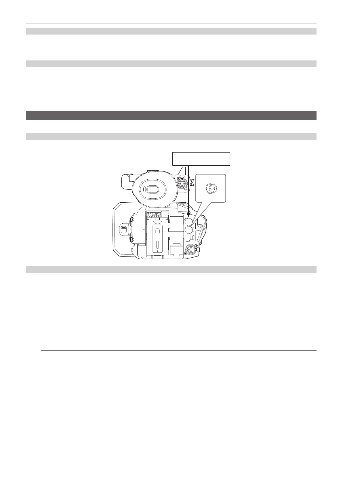
– 50 –
Chapter 3 Preparation — Setting of time data
Time code function during battery replacement
The operation of the time code generator will continue by the backup mechanism functioning even when replacing the battery.
The time code of the free run may shift when any item in the [SYSTEM] menu → [FREQUENCY], [FILE FORMAT], or [REC FORMAT] is changed. Set
the power to < j > (ON) again, conrm the time code, and set it again if necessary.
Time code in variable frame rate recording/super slow recording
The time code is xed to [REC RUN] when the variable frame rate recording function or the super slow recording function is enabled. The time code will
advance while recording at a speed corresponding to the ratio of the recording frame frequency of [REC FORMAT] and the setting values in the [SCENE
FILE] menu → [FRAME RATE].
As an example, the time code will advance 60/24 frames per second (two seconds 12 frames) when the recording frame frequency of [REC FORMAT] is
set to 23.98p and the [SCENE FILE] menu → [FRAME RATE] is set to [60fps].
f The time code output from the <TC IN/OUT> terminal or the <SDI OUT> terminal is advanced in 1x speed from the exact start of recording.
Presetting the time code to external
The internal time code generator of the camera can be slave locked in a simplied manner to an external generator.
Connection example of the camera and an external generator
Connect the reference time come to the <TC IN/OUT> terminal.
Reference time code
External lock
Externally lock the time code.
f Connect the camera to an external generator in advance.
1
Select the [RECORDING] menu → [TC/UB] → [FREE/REC RUN] → [FREE RUN].
2
Select the [RECORDING] menu → [TC/UB] → [TC IN/OUT SEL] → [TC IN].
3
Enter the external time code to the <TC IN/OUT> terminal.
[TCG] in the camera image screen will be displayed in black and white inversion.
Enter the time code matching the setting in the [SYSTEM] menu → [REC FORMAT] as the reference time code.
Enter the time code of the non-drop frame as well for 23.98p, 25.00p, 50.00p, and 50.00i.
@
NOTE
t Do not slave lock to the externally input time code but automatically advance with internal reference during recording or rec remote controlling of
the external recording device.
The time code value may overlap or drop out after recording or ending rec remote due to performing slave lock to the time code input from
external.
t Since this camera does not have a genlock system, the time code may shift one frame.
t Once the slave lock is performed, it will maintain the slave lock status even when the input from the <TC IN/OUT> terminal is gone. However, the
slave lock status will be cleared in following cases.
‑ When the time code is set in [TC PRESET]
‑ When the power is turned off
‑ When switched [DF]/[NDF]
‑ When set to [REC RUN]
‑ When the variable frame rate recording function or super slow recording function is enabled
t The pre-recording will be discarded once when the slave lock is performed during pre-recording.
t The number of frames for the record start time code may not be a multiple of four when the recording frame frequency of [REC FORMAT] is set to
23.98p.
t External locks by user bits are not supported.
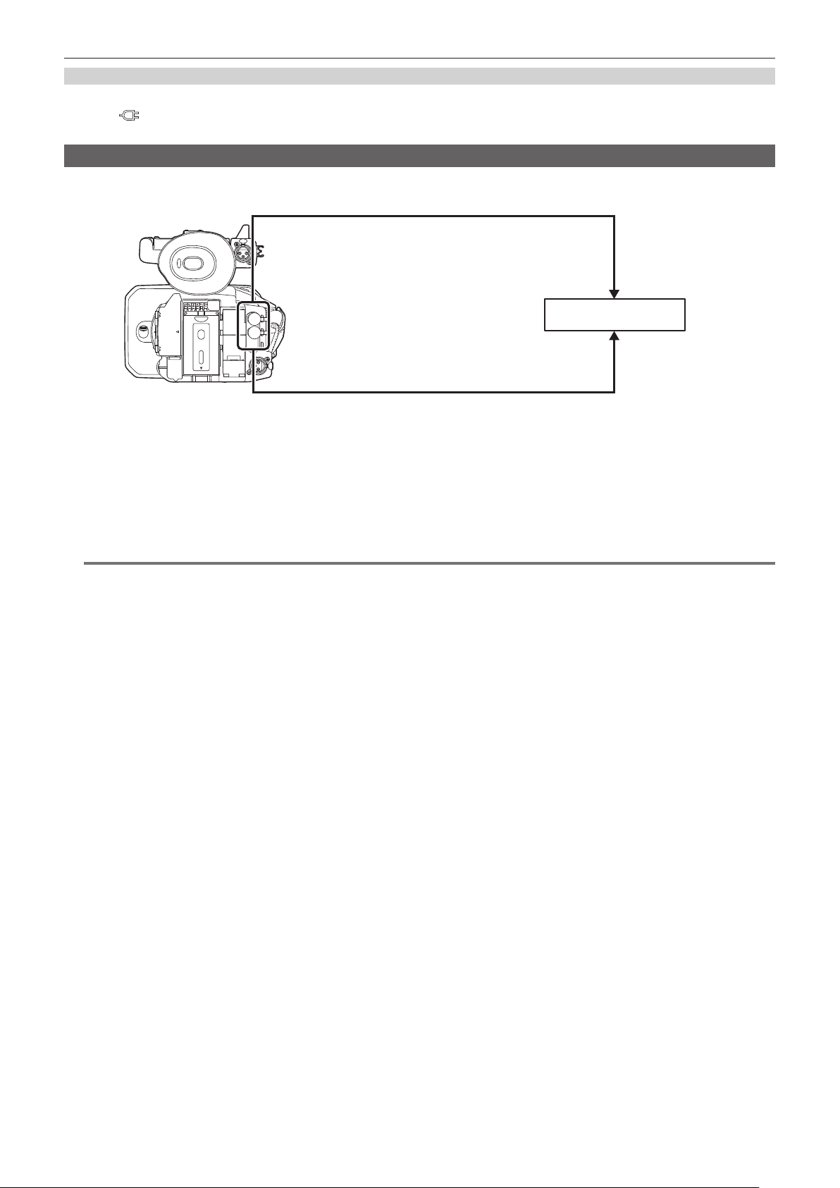
– 51 –
Chapter 3 Preparation — Setting of time data
Cautions when switching the power supply from the battery to the AC adaptor while an external lock is active
To maintain the continuity of the time code generator power, remove the battery only after the power status display in the camera image screen has
changed to
after connecting the AC adaptor to the <DC IN 12V> terminal. The continuity of the external lock of the time code is not guaranteed
when the battery is removed rst.
Supplying the time code externally
The time code output from the camera corresponding to the camera video or the playback video can be supplied to an external recording device.
<TC IN/OUT> terminal
<SDI OUT> terminal
SDI IN terminal
TC IN terminal
VTR, etc.
1
Select the [RECORDING] menu → [TC/UB] → [TC IN/OUT SEL] → [TC OUT].
2
Select the [RECORDING] menu → [TC/UB] → [TC OUT REF] → [RECORDING].
The same time code can be recorded to the video of the same time on two devices.
r To match the time code output from the <TC IN/OUT> terminal to the video of the SDI output or the monitor output
1
Select the [RECORDING] menu → [TC/UB] → [TC OUT REF] → [SDI OUT].
@
NOTE
t TCR is output during playback. TCG output during playback is not supported.
t The time code output may shift by 1 frame when the recording frame frequency of [REC FORMAT] is set to 23.98p.
t External locks by user bits are not supported.
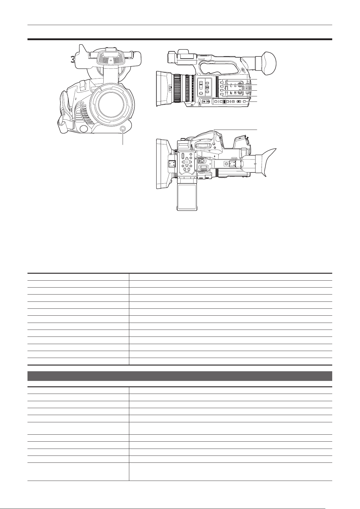
– 52 –
Chapter 3 Preparation — Assigning function to the USER buttons
Assigning function to the USER buttons
<USER 7> button
<USER 1> button
<USER 6> button
<USER 2> button
<USER 3> button
<USER 5> button
<USER 4> button
Selected function can be assigned to the USER buttons.
The USER buttons have seven USER buttons on the camera (<USER 1> to <USER 7> buttons) and ve USER button icons displayed on the LCD
monitor ([USER8] to [USER12] button icons).
The <USER 1> to <USER 7> buttons can be used as the USER buttons when the camera image screen is displayed.
The [USER8] to [USER12] button icons can be used as the USER buttons when the operation icon screen is displayed.
1
Select the function to assign to each in the [CAMERA] menu → [USER SW] → [USER1] to [USER12].
r Functions assigned to the USER buttons in the factory setting
USER button Function
<USER 1> button [O.I.S.]
<USER 2> button [ZEBRA]
<USER 3> button [WFM]
<USER 4> button [A.IRIS LEVEL]
<USER 5> button [SLOT SEL]
<USER 6> button [IRIS]
<USER 7> button [AWB]
[USER8] [IR REC]
[USER9] [FOCUS MACRO]
[USER10] [AREA]
[USER11] [ATW LOCK]
[USER12] [MENU]
Functions assigned to USER buttons
Item Description
[INHIBIT] Disables assignment of functions.
[AWB] Assigns the automatic white balance function.
[DRS] Assigns the dynamic range stretcher function.
[FBC] Enables/disables the ash band compensation function.
[ONE PUSH AF] Assigns the one-push auto focus function.
The same is performed when the <PUSH AUTO> button is pressed.
[S.GAIN] Assigns the function that increases the gain to 24 dB or more.
[AREA] Assigns the area function.
[AF AREA] Assigns the area auto focus function.
[ATW] Enables/disables the auto tracking white balance functions.
[ATW LOCK] Fixes the value of the white balance. Press the USER button again or touch the USER button icon to
resume the operation of the auto tracking white balance.
f Enable when the auto tracking white balance is operating.

– 53 –
Chapter 3 Preparation — Assigning function to the USER buttons
Item Description
[SPOTLIGHT] Enables/disables the auto iris control function for the spot light.
[BACKLIGHT] Enables/disables the auto iris control function for the backlight compensation.
[A.IRIS LEVEL] Enables/disables the auto iris level function.
[IRIS] Assigns the function that switches the auto iris and manual iris.
[Y GET] Assigns the function that displays the luminance level of the frame area displayed near the center.
[FOCUS MACRO] Switches the focus macro setting.
[O.I.S.] Enables/disables the optical image stabilizer function.
[i.ZOOM] Assigns the zoom function to minimize image distortion.
[D.ZOOM] Enables/disables the digital zoom. Zooms in on the eld angle by 2x, 5x, and 10x vertically and horizontally
each time the USER button is pressed or the USER button icon is touched.
[IR REC] Enables/disables the IR recording.
[FAST ZOOM] Speeds up the zoom speed when the zoom lever is pushed in all the way.
[PRE REC] Enables/disables the pre-recording.
[VFR] Enables/disables the variable frame rate recording function.
[SUPER SLOW] Enables/disables the super slow recording function.
[REC CHECK] Automatically plays back the last approximately three seconds of the previously shot clip.
[BACKGR PAUSE] Assigns the function that stops the background recording of card slot 2.
Press and hold the USER button to which [BACKGR PAUSE] is assigned for approximately ve seconds
or touch and hold the USER button icon for approximately ve seconds and release to stop background
recording.
[DEL LAST CLIP] Deletes the clip last shot.
[SLOT SEL] Selects the card slot with the memory card for recording inserted.
Or, switches the card slot for the clip to display in the thumbnail screen.
[EXPAND] Enables/disables the enlarged display function (focus assist function).
[PEAKING] Enables/disables the peaking display (focus assist function).
[WFM] Switches the display of the waveform monitor. The waveform display is selected in the [VIDEO OUT/LCD/
VF] menu → [EI ASSIST] → [WFM MODE].
[ZEBRA] Displays/hides zebra patterns.
[LEVEL GAUGE] Displays/hides the level gauge.
[LEVEL GAUGE SET] Sets the current horizontal and vertical direction as the reference value of the level gauge.
[LCD/VF HDR] Toggles output images from the LCD monitor between the high dynamic range and standard dynamic
range.
[VF ON/OFF] Forces images to be displayed in the viewnder.
[LCD/VF DETAIL] Adjusts the intensity for the contour of the video in the viewnder or LCD monitor to make it easier to
focus.
[AUDIO MON SEL] Switches the audio channel 1/2 and the audio channel 3/4 for the output audio (headphone terminal, built-
in speaker, <AV OUT> terminal) while the USER button is pressed or the USER button icon is touched.
Also, the display of the audio level meter is switched between the audio channel 1/2 and the audio channel
3/4.
[MENU] Switches display/hide of the menu.
[LOAD SETUP FILE] Selects the setup le saved on the memory card to load on the camera.
[LCD BACKLIGHT]
Switches the brightness of the LCD monitor. Toggles [0], [1], [2], and [−1] in order each time the USER
button is pressed or the USER button icon is touched.
[CARD READER MODE] Enables/disables the card reader mode function (USB mass storage function).
f Release the connection to enable the card reader mode when connected to a network via a wireless
LAN. (The camera returns to the original setting when the card reader mode is disabled.)
[STREAMING START] Starts/stops streaming from the camera.
Streaming starts only during RTMP streaming.
@
NOTE
t Following functions will be disabled when the camera is set to < h > (standby) and then turned on again.
[FBC], [S.GAIN], [AREA], [AF AREA], [ATW LOCK], [SPOTLIGHT], [BACKLIGHT], [Y GET], [D.ZOOM], [FAST ZOOM], [EXPAND], [PEAKING],
[WFM], [VF ON/OFF], [AUDIO MON SEL], [CARD READER MODE], [STREAMING START]
Checking the function assigned to the USER buttons
You can check the function assigned to the USER buttons in the SWITCH screen of the mode check. For details, refer to “Mode check display”
(page 166).

– 54 –
Chapter 3 Preparation — Adjusting and setting the LCD monitor
Adjusting and setting the LCD monitor
Using the LCD monitor
This camera is equipped with a 3.15-inch LCD monitor. Use either the viewnder or the LCD monitor depending on your purpose and the shooting
conditions.
Fig. 1 Fig. 2
1
Open the LCD monitor. (Fig. 1)
The light goes on when the LCD monitor is opened. The light goes off when it is closed.
2
Turn the LCD monitor to a comfortable viewing angle. (Fig. 2)
Turns 90° toward the lens and 180° toward you.
@
NOTE
t When closing the LCD monitor, be sure to close it rmly.
t Take care not to apply excessive force on the LCD monitor when it is opened. Doing so may result in a malfunction.
t Condensation sometimes forms on the LCD panel of the LCD monitor in locations subject to extreme temperature differences. If this happens, wipe
with a soft, dry cloth.
t If the camera is very cold, the LCD monitor will be slightly darker than normal immediately after the power is turned on. The brightness will return to
normal when the internal temperature increases.
t The image brightness and color hue seen on the viewnder and LCD monitor may be different from that seen on a TV monitor. The nal check of the
image should be done on a TV monitor.
Adjusting the LCD monitor
r Adjusting the brightness, contrast, and color level
[BRIGHTNESS] (brightness), [CONTRAST] (contrast), and [COLOR LEVEL] (color level) can be adjusted in the [VIDEO OUT/LCD/VF] menu → [LCD].
The adjustments of the LCD monitor do not affect the images output or recorded by the camera.
r Adjusting the backlight luminance
Switches the brightness of the LCD monitor backlight. There are the following two methods:
f Set with the [VIDEO OUT/LCD/VF] menu → [LCD] → [BACK LIGHT].
f Toggles [0], [1], [2], and [−1] in order each time the USER button to which [LCD BACKLIGHT] is assigned is pressed or the USER button icon is
touched.
Mirror shooting
When recording with the LCD monitor rotated towards the lens side, if the camera is set to the [VIDEO OUT/LCD/VF] menu → [LCD] → [SELF SHOOT]
→ [MIRROR], the image is displayed in reverse in left and right on the LCD monitor. This allows shooting as if looking at a mirror image. Note that only
the display of the LCD monitor is horizontally reversed. The settings for mirror shooting do not affect the images output or recorded by the camera.
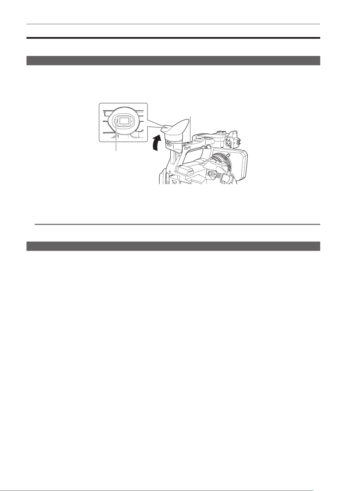
– 55 –
Chapter 3 Preparation — Adjusting and setting the viewnder
Adjusting and setting the viewnder
This camera is equipped with a 0.39-inch organic EL viewnder. Use either the viewnder or the LCD monitor depending on your purpose and the
shooting conditions.
Using the viewnder
When the LCD monitor is difcult to use because the surroundings are bright, you can check the image using the viewnder.
Positioning your eye near the viewnder will trigger the eye sensor to automatically display the image.
f The sensitivity of the eye sensor is set in the [VIDEO OUT/LCD/VF] menu → [VF] → [EYE SENSOR] → [HIGH] or [LOW].
f The eye sensor may not work properly depending on the shape of the eyeglasses you may be wearing, how you hold the camera, or by strong light
present in the vicinity of the eyepiece. If this happens, switch the image display by assigning [VF ON/OFF] to the USER button.
Diopter adjustment lever
Eye sensor
1
Move the viewfinder in the vertical direction to adjust the screen to a comfortable angle.
The viewnder can be lifted vertically to approximately 90 degrees.
2
Adjust the characters on the viewfinder screen so that they are clearly visible using the diopter adjustment lever.
@
NOTE
t The image brightness and color hue seen on the viewnder and LCD monitor may be different from that seen on a TV monitor. The nal check of the
image should be done on a TV monitor.
Adjusting the viewnder
r Adjusting the brightness, contrast, and color level
Adjust [BRIGHTNESS] (brightness), [CONTRAST] (contrast), and [COLOR LEVEL] (color level) in the [VIDEO OUT/LCD/VF] menu → [VF].
The adjustments for the viewnder do not affect the images output or recorded by the camera.
r Switching between color and monochrome
The viewnder screen can toggle between a color display and monochrome display. Set the display with the [VIDEO OUT/LCD/VF] menu → [VF] → [VF
COLOR].

– 56 –
Chapter 3 Preparation — Tally lamp
Tally lamp
The front tally lamp and the rear tally lamp can be illuminated during the shooting.
1
Select the [OTHERS] menu → [LED] → [TALLY LED] → [FRONT]/[REAR]/[BOTH].
f The tally lamp will ash when the camera is in the following status.
‑ When the remaining recording capacity of the memory card or the remaining battery level is low (one time per second)
‑ When the memory card has no more space to record (four times per second)
‑ When a warning such as a system error or a recording abnormality has occurred (four times per second)
@
NOTE
t The tally lamp will not illuminate or ash when the [OTHERS] menu → [LED] → [TALLY LED] → [OFF] is set.

This chapter describes how to operate the screen of this camera, how to operate the menu, the structure of the menu, and details of the menu.
Chapter 4 Operation
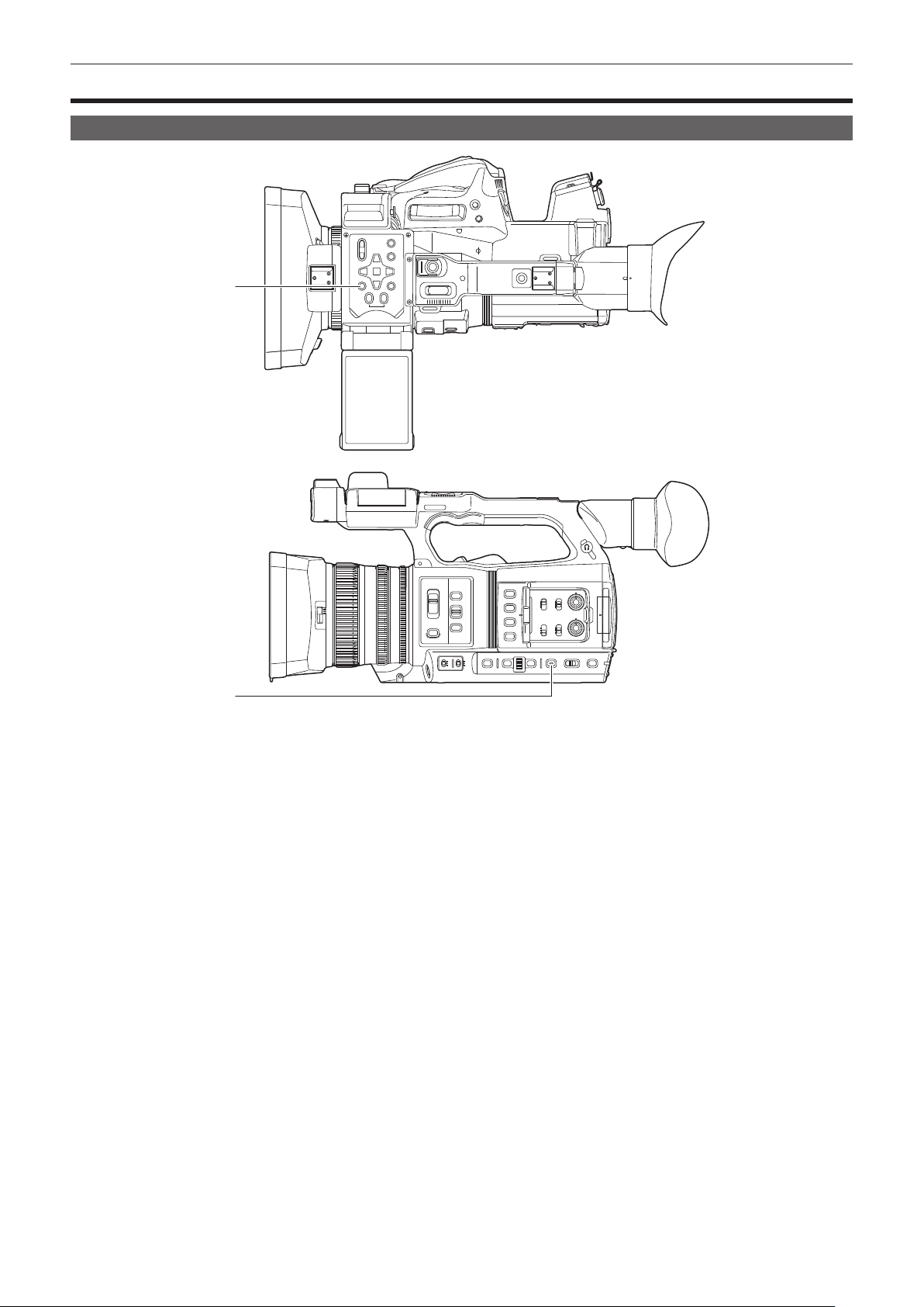
– 58 –
Chapter 4 Operation — Basic operation of the screen
Basic operation of the screen
Major button operation and screen display
1
2
1 <THUMBNAIL> button
2 <DISP/MODE CHK> button
r <THUMBNAIL> button
Displays the thumbnail screen.
Playback, copy, delete, or protect of a clip can be performed.
For details about the thumbnail screen, refer to “Thumbnail operation” (page 147).
r <DISP/MODE CHK> button
Press while the camera image screen is displayed to display or hide most of the items.
Press the <DISP/MODE CHK> button for one second or more while displaying the camera image screen to display the STATUS screen of the mode
check.
Each setting and the status of the camera can be conrmed.
For details about each screen of the mode check, refer to “Mode check display” (page 166).
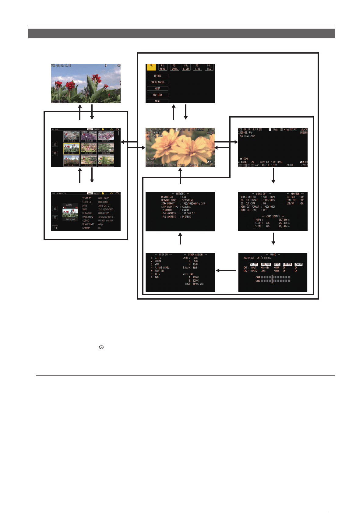
– 59 –
Chapter 4 Operation — Basic operation of the screen
Major button operation and switching screen
Switches the screen as follows when the <DISP/MODE CHK> button, <EXIT> button, <THUMBNAIL> button, <SET> button or <(> button is pressed.
3
3 4
1
7
1
1
1
1
6 4
4 8
2 5
Thumbnail screen
Playback screen Operation icon screen
Camera image screen Mode check STATUS screen
Mode check FUNCTION screen
Mode check AUDIO screenMode check SWITCH screen
Mode check NETWORK screen
Clip information
1 Press the <DISP/MODE CHK> button.
2 Press the <SET> button or multidial.
3 Press the <THUMBNAIL> button.
4 Press the <EXIT> button.
5 Press the <THUMBNAIL> button or the <(> button.
6 Press the multidial when the [
ICONS] is displayed.
7 Press the <DISP/MODE CHK> button for one second or more.
8 Select the [THUMBNAIL] menu → [CLIP] → [INFORMATION].
@
NOTE
t The camera image screen is displayed when the camera is turned on.
t The camera image screen is automatically displayed if recording starts while the thumbnail screen, playback screen or clip information is displayed.
t The playback screen is displayed if a clip is selected in the thumbnail screen.
t The thumbnail screen is displayed if the playback of the clip ends or playback is stopped.
t The operation icon screen is displayed if the LCD monitor is touched for one second or more while the camera image screen is displayed.
t The camera changes to the camera image screen if any area other than the icon in the operation icon screen is touched. The camera image screen is
displayed automatically after ve seconds without any operation of the multidial or touch operation in the operation icon screen.
t The camera image screen is automatically displayed after ve seconds without operation of the <DISP/MODE CHK> button in each screen of the
mode check.
The screen will not switch to the camera image screen while the <DISP/MODE CHK> button is pressed.
t The camera image is displayed in the operation icon screen and each screen for the mode check.

– 60 –
Chapter 4 Operation — Operating each screen
Operating each screen
Camera image screen
Displays the shooting screen.
For details about the camera image screen, refer to “Screen status display” (page 160).
Thumbnail screen
Playback, copy, delete, or protect of a clip can be performed.
For details about the thumbnail screen, refer to “Thumbnail operation” (page 147).
Operation icon screen
You can select the scene le or operate the functions assigned to [USER8] through [USER12].
For details about the operation icon screen, refer to “Operation icon screen display” (page 143).

– 61 –
Chapter 4 Operation — Basic operation of the menu
Basic operation of the menu
The setting of the camera can be changed with the menu in accordance to the shooting scene or recording contents.
Set data is written and saved in the camera memory.
f There are two methods of operation: a method to operate with the multidial, or a method to touch the LCD monitor.
Conguration of the menu
Menu types and how to open them
The [OPTION] menu is not displayed on AJ-UPX360ED.
Menu type Use How to open
Menu The menu is structured in categorized levels according to
intended use and setting frequency.
Displayed by pressing the <MENU> button.
[OPTION] menu A special menu is prepared considering additional
functions in the future.
Displayed by pressing the <MENU> button while holding
down the <EXIT> button.
Conguration of the menu
[THUMBNAIL] menu Performs conrmation or deleting of the recording clip.
This menu can be set when the thumbnail screen is displayed.
[CAMERA] menu Sets the basic function of the camera.
This menu cannot be set when the thumbnail screen is displayed.
[SCENE FILE] menu Sets the setting regarding scene le.
This menu sets the detailed image quality adjustment of the camera video. Also, selection of the scene le, writing the
scene le data to the camera memory, and loading from the camera memory can be performed.
This menu cannot be set when the thumbnail screen is displayed.
[AUDIO] menu Sets the input/output function of audio.
[VIDEO OUT/LCD/VF] menu Congures the settings for the external output, the information to display in the LCD monitor or viewnder and the output
format.
[RECORDING] menu Sets the various items in the recording function.
[NETWORK] menu Sets the setting regarding the network function.
[SYSTEM] menu Congures the settings regarding the recording format of video and audio.
[OTHERS] menu Congures the settings for writing/loading/initializing user les to the internal memory, and the basic camera settings.
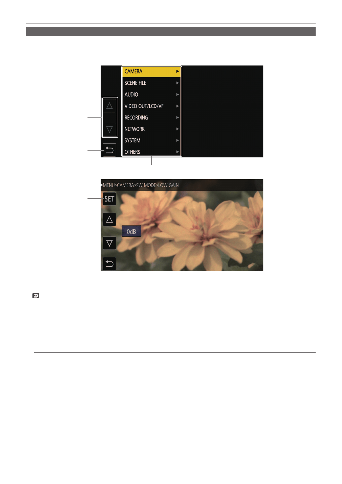
– 62 –
Chapter 4 Operation — Basic operation of the menu
Displaying the menu
Displays the menu, and select the menu or item to set.
1
Press the <MENU> button when not recording.
The menu is displayed.
4
5
1
2
3
1 [`]/[{]
Toggles the page or changes the value when selected.
These button icons are not available if they cannot be changed.
2
Returns to one level higher from the current menu when selected.
3 Menu
Moves to one level lower from the current menu, or to the setting screen when selected.
4 Level display
Displays the path of the menu to the currently displayed screen.
5 [SET]
Conrms the set value when selected.
@
NOTE
t The menu displayed in gray characters cannot be changed.
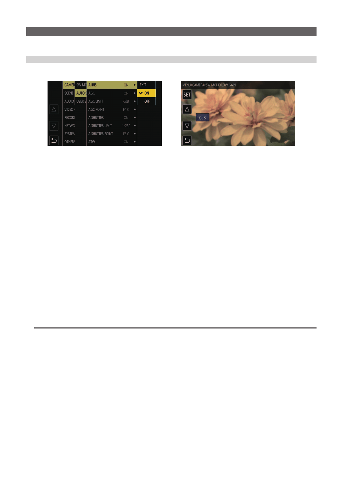
– 63 –
Chapter 4 Operation — Basic operation of the menu
Operating the menu
Various settings are possible from the menu.
There are two methods of operation: a method to operate with the multidial, or a method to touch the LCD monitor.
When operating with the multidial
Operate the multidial on the camera by turning it in vertical direction or pushing it.
Operations can also be performed by pressing the <%> button, <(> button, <)> button, <=/&> button and <SET> button.
Fig. 1 Fig. 2
1
Press the <MENU> button when not recording.
The menu is displayed.
2
Select the menu to set.
1) Turn the multidial to move the cursor to the menu to set.
The cursor can also be moved by pressing the <(> button and <=/&> button.
2) Press the multidial or the <SET> button.
The lower level menu is displayed.
f The conrmation screen is displayed depending on the menu.
f Perform the similar operation if there is next level.
f In some menus, a screen to set the numeric value is displayed in the camera image screen (Fig. 2).
f In some menus, a message is displayed if a menu cannot be executed.
f Press the <EXIT> button or the <%> button to return to one level higher.
3
Select the item to set.
1) Turn the multidial to move the cursor to the item to set.
The cursor can also be moved by pressing the <(> button and <=/&> button.
2) Press the multidial or the <SET> button.
A check mark is displayed at the left of the set item. (Fig. 1)
f Press the <EXIT> button or the <%> button to return to one level higher.
4
Press the <MENU> button to close the menu.
f Depending on the operating item, it will automatically return to the previous screen.
@
NOTE
t In the screen to set the numeric value (Fig. 2), press down and turn the multidial in the desired direction and x it, or press and hold the <(> button
and the <=/&> button to change the value at high speed.
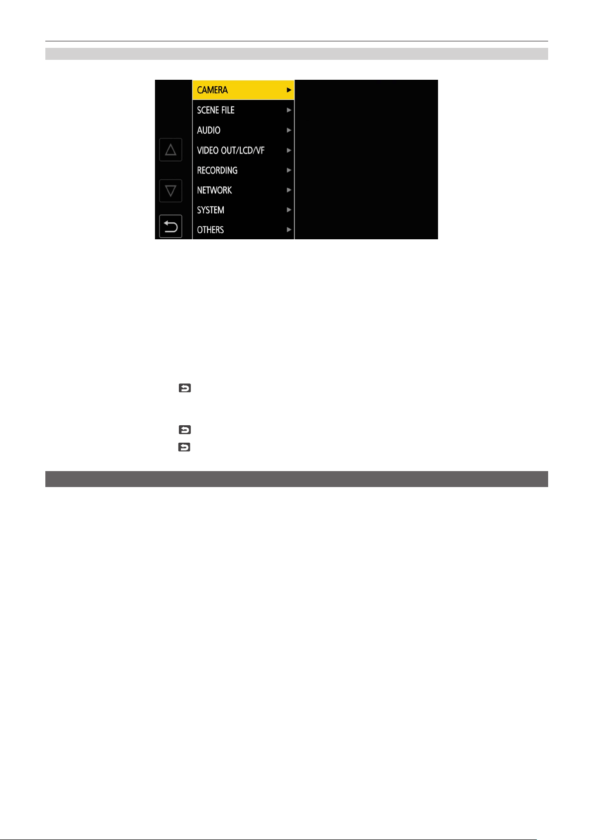
– 64 –
Chapter 4 Operation — Basic operation of the menu
When operating by touching the LCD monitor
Operate by touching the LCD monitor.
1
Press the <MENU> button when not recording.
The menu is displayed.
2
Select the menu to set.
f Touch the menu to set. The lower level menu is displayed.
f The conrmation screen is displayed depending on the menu.
f Perform the similar operation if there is next level.
f In some menus, a screen to set the numeric value is displayed in the camera image screen.
To change the numeric value, touch [`]/[{] and change the setting value.
f In some menus, a message is displayed if a menu cannot be executed.
f Touch [`]/[{] to toggle the pages.
The button icons cannot be touched if there are no more pages.
f To return to one level higher, touch
.
3
Select the item to set.
f Touch the item to set. A check mark is displayed at the left of the set item.
f To return to one level higher, touch
.
4
Exit from the menu by touching
, or pressing the <MENU> button.
f Depending on the operating item, it will automatically return to the previous screen.
Initializing the menu
The menu can be returned to the factory setting condition.
1
Select the [OTHERS] menu → [MENU INITIALIZE].
2
Select [YES] when the confirmation message is displayed.
The setting value of the menu is returned to the factory setting.
– 65 –
Chapter 4 Operation — Menu settings
Menu settings
[THUMBNAIL] menu
Performs conrmation or deleting of the recording clip.
This menu can be set when the thumbnail screen is displayed.
[PLAYBACK]
Sets the playback of recorded clips.
The clip selection is generally [ALL SLOT] when toggling the thumbnail screen from the camera image screen.
[CLIP SEL]
Selects a clip to be displayed on the thumbnail screen.
[ALL SLOT] Displays the clips recorded on all the memory cards in each card slot.
[SLOT1] Displays only the clips recorded on the memory card in card slot 1.
[SLOT2] Displays only the clips recorded on the memory card in card slot 2.
[SAME FORMAT] Displays only the clips recorded in the same format as the system format.
Clips recorded in the same format means that each item of [FREQUENCY], [FILE FORMAT], and [REC FORMAT] in the
[SYSTEM] menu matches the current setting status.
(Factory setting: [ALL SLOT])
[RESUME PLAY]
Select if the playback is to start from the position the playback has stopped or not.
[ON] Plays back from the position where playback has stopped.
[OFF] Always starts the playback from the beginning of the clip.
(Factory setting: [OFF])
[CLIP]
The clip can be protected or copied to a different memory card.
[PROTECT] [SELECT] Protect the clip so it is not mistakenly deleted.
Select the clip to protect, and set the protect.
[DELETE] [ALL] Deletes all the clips displayed in the thumbnail screen.
The clip that is not displayed in the thumbnail screen is not deleted.
[SELECT] Select the clip to delete, and delete it.
[COPY] [ALL] Copies all clips to a different memory card.
[SELECT] Selects the clip to copy, and copies the clip to a different memory card.
[REPAIR]
Repairs a clip displaying
caused by the sudden power loss, etc., during recording in
P2 format.
[INFORMATION] Displays the detailed information of the clip.
@
NOTE
t The clip recorded in P2 format cannot be protected.
t The clip recorded in MOV format cannot be copied.
[DISPLAY]
Sets the display of the thumbnail screen.
[DATA]
Selects the content to be displayed in the time code display area.
[START TC] Displays the time code value at the start of the recording.
[CLIP NAME] Displays clip names.
(Factory setting: [START TC])
[CAMERA] menu
Sets the basic camera function.
This menu cannot be set when the thumbnail screen is displayed.
[SW MODE]
[LOW GAIN]
Sets the gain value to be assigned to the <L> position of the <GAIN> switch. (The negative value of gain can be set only when [SYSTEM] menu →
[SHOOTING MODE] → [HIGH SENS.] is set.)
The items that can be set are as follows.
f [−3dB]…[18dB]

– 66 –
Chapter 4 Operation — Menu settings
(Factory setting: [0dB])
[MID GAIN]
Sets the gain value to be assigned to the <M> position of the <GAIN> switch.
The items that can be set are as follows.
f [−3dB]…[18dB]
(Factory setting: [6dB])
[HIGH GAIN]
Sets the gain value to be assigned to the <H> position of the <GAIN> switch.
The items that can be set are as follows.
f [−3dB]…[18dB]
(Factory setting: [12dB])
[SUPER GAIN]
Sets the super gain to be assigned to the USER button.
Toggles [24dB], [30dB], [36dB], and the normal gain in order each time the USER button is pressed or the USER button icon is touched when set to
[ALL].
The items that can be set are as follows.
f [24dB], [30dB], [36dB], [ALL]
(Factory setting: [36dB])
[O.I.S.]
Enables/disables the optical image stabilizer function.
If [O.I.S.] is assigned to the USER button, pressing the USER button switches [ON]/[OFF].
For details about optical image stabilizer, refer to “Optical image stabilizer function” (page 140).
[ON] Enables the optical image stabilizer function.
[OFF] Disables the optical image stabilizer function.
(Factory setting: [ON])
[HYBRID O.I.S.]
Enables/disables the hybrid optical image stabilizer function.
For details about optical image stabilizer, refer to “Optical image stabilizer function” (page 140).
[ON] Enables the hybrid optical image stabilizer function.
[OFF] Disables the hybrid optical image stabilizer function.
(Factory setting: [ON])
[O.I.S. MODE]
Switches the operation mode of the optical image stabilizer function.
[NORMAL] Species the standard setting for a good balance of correction for large and small camera shake.
[PAN/TILT] Species a setting appropriate for shooting that uses a lot of panning and tilting of the camera.
[STABLE] Species a setting appropriate for xing a composition to shoot a subject.
(Factory setting: [NORMAL])
[ATW]
Assigns the auto tracking white balance function to the <WHITE BAL> switch.
The items that can be set are as follows.
f [Ach], [Bch], [PRE], [OFF]
(Factory setting: [OFF])
[ATW SPEED]
Sets the control speed of the auto tracking white balance function.
The items that can be set are as follows.
f [FAST], [NORMAL], [SLOW]
(Factory setting: [NORMAL])
[ATW TARGET R]
Finely adjusts the Rch output for convergence with the auto tracking white balance operation.
The items that can be set are as follows.
f [−10]…[10]
(Factory setting: [0])
[ATW TARGET B]
Finely adjusts the Bch output for convergence with the auto tracking white balance operation.
The items that can be set are as follows.
f [−10]…[10]
(Factory setting: [0])

– 67 –
Chapter 4 Operation — Menu settings
[W.BAL PRESET]
Sets the color temperature to be assigned to the <PRST> position of the <WHITE BAL> switch.
The items that can be set are as follows.
f [3200K], [5600K], [VAR]
(Factory setting: [3200K])
[W.BAL VAR]
Sets the value of [VAR] in [W.BAL PRESET].
The setting can also be operated by the multidial button.
Enabled when [W.BAL PRESET] is set to [VAR] and the <WHITE BAL> switch is at <PRST>.
The items that can be set are as follows.
f [2000K]…[15000K]
(Factory setting: [3200K])
[H.ZOOM SPEED]
Sets the zoom speed of the handle zoom.
The items that can be set are as follows.
f [1]…[99]
(Factory setting: [50])
[i.ZOOM]
Keeps the image quality while performing digital zoom.
[ON] Enables the i.ZOOM function.
[OFF] Disables the i.ZOOM function.
(Factory setting: [OFF])
[MF ASSIST]
Sets whether to adjust the last focus automatically when in the manual focus mode.
If the image is largely out of focus, the focus may not be adjusted properly.
[ON] Adjusts the last focus automatically.
[OFF] Does not adjust the focus automatically.
(Factory setting: [OFF])
[MACRO]
Enables/disables the focus macro function.
If functions are assigned to the USER buttons, [ON]/[OFF] can be switched using the USER button operations.
[ON] Enables the focus macro function.
[OFF] Disables the focus macro function.
(Factory setting: [OFF])
[AF AREA WIDTH]
Adjusts the width of the area enable for the auto focus to match the size of the subject.
The items that can be set are as follows.
f [ON], [OFF]
(Factory setting: [OFF])
[A.IRIS SPEED]
Sets the control speed of the auto iris level function.
The items that can be set are as follows.
f [FAST], [NORMAL], [SLOW]
(Factory setting: [NORMAL])
[A.IRIS WINDOW]
Selects the auto iris detection window.
[NORMAL1] Window that is around center of the screen.
[NORMAL2] Window that is around bottom of the screen.
[CENTER] Window that is a spot around center of the screen.
(Factory setting: [NORMAL1])
[AREA MODE]
Assign the function that is performed within the area selected by touching the LCD monitor or pressing the <%> button, <(> button, <)> button,
or <=/&> button while shooting.
[INHIBIT] Disables assignment of functions.
[FOCUS] Assigns the auto focus function.
[IRIS] Assigns the auto iris function.
– 68 –
Chapter 4 Operation — Menu settings
[Y GET] Assigns the brightness display function.
[FOCUS/IRIS] Assigns the simultaneous operation of the [FOCUS] and [IRIS].
[FOCUS/Y GET] Assigns the simultaneous operation of the [FOCUS] and [Y GET].
(Factory setting: [INHIBIT])
[IR REC]
Enables/disables the IR recording.
The items that can be set are as follows.
f [ON], [OFF]
(Factory setting: [OFF])
[AUTO SW]
[A.IRIS]
Enables/disables the auto iris control.
[ON] Performs the auto iris control operation when in auto mode. The <IRIS> button does not work.
[OFF] Does not perform the auto iris control operation when in auto mode.
This activates the iris control selected with the <IRIS> button.
(Factory setting: [ON])
[AGC]
Sets the auto gain control operations when [ON] is selected in [A.IRIS].
[ON] Performs the operation of the [AGC] function that automatically adjusts camera gain when in auto mode.
[OFF] Does not perform the operation of the [AGC] function that automatically adjusts camera gain when in auto mode.
(Factory setting: [ON])
[AGC LIMIT]
Sets the maximum gain value during [AGC] operation.
The items that can be set are as follows.
f [3dB], [6dB], [12dB], [18dB]
(Factory setting: [6dB])
[AGC POINT]
Sets the F value to switch control from auto iris to [AGC] during [AGC] operation.
The items that can be set are as follows.
f [F4.0], [F5.6]
(Factory setting: [F4.0])
[A.SHUTTER]
Sets the auto shutter control operations when [ON] is selected in [A.IRIS].
[ON] Performs the operation of the auto shutter when in auto mode.
[OFF] Does not perform the operation of the auto shutter when in auto mode.
(Factory setting: [ON])
[A.SHUTTER LIMIT]
Sets the maximum shutter value during [A.SHUTTER] operation.
The items that can be set are as follows.
f [1/100], [1/120], [1/250]
(Factory setting: [1/250])
[A.SHUTTER POINT]
Sets the F value to switch control from auto iris to [A.SHUTTER] during [A.SHUTTER] operation.
The items that can be set are as follows.
f [F8.0], [F9.6]
(Factory setting: [F8.0])
[ATW]
Sets the operations of the auto tracking white balance function.
[ON] Activates the auto tracking white balance function when in auto mode. The [ATW] function cannot be switched between
enabled and disabled with the <WHITE BAL> switch or the USER buttons.
However, if [ATW LOCK] is assigned to the USER button, the white balance value can be xed with the USER button.
[OFF] Does not perform the [ATW] function operation in auto mode. Performs the operation of the white balance function selected
with the <WHITE BAL> switch.
(Factory setting: [ON])
– 69 –
Chapter 4 Operation — Menu settings
[AF]
Sets the operation of the auto focus.
[ON] Performs the operation of the auto focus when in auto mode.
The <FOCUS> switch does not work.
[OFF] Does not perform the operation of the auto focus when in auto mode.
Performs the operation of the focus selected with the <FOCUS> switch.
(Factory setting: [ON])
[USER SW]
Sets the function to assign to the <USER 1> to <USER 7> buttons or the [USER8] to [USER12] button icons.
For details, refer to “Assigning function to the USER buttons” (page 52).
Following functions can be assigned to [USER1] to [USER12].
f [INHIBIT], [AWB], [DRS], [FBC], [ONE PUSH AF], [S.GAIN], [AREA], [AF AREA], [ATW], [ATW LOCK], [SPOTLIGHT], [BACKLIGHT], [A.IRIS
LEVEL], [IRIS], [Y GET], [FOCUS MACRO], [O.I.S.], [i.ZOOM], [D.ZOOM], [IR REC], [FAST ZOOM], [PRE REC], [VFR], [SUPER SLOW], [REC
CHECK], [BACKGR PAUSE], [DEL LAST CLIP], [SLOT SEL], [EXPAND], [PEAKING], [WFM], [ZEBRA], [LEVEL GAUGE], [LEVEL GAUGE SET],
[LCD/VF HDR], [VF ON/OFF], [LCD/VF DETAIL], [AUDIO MON SEL], [MENU], [LOAD SETUP FILE], [LCD BACKLIGHT], [CARD READER MODE],
[STREAMING START]
[USER1] Sets the function to assign to the <USER 1> button.
(Factory setting: [O.I.S.])
[USER2] Sets the function to assign to the <USER 2> button.
(Factory setting: [ZEBRA])
[USER3] Sets the function to assign to the <USER 3> button.
(Factory setting: [WFM])
[USER4] Sets the function to assign to the <USER 4> button.
(Factory setting: [A.IRIS LEVEL])
[USER5] Sets the function to assign to the <USER 5> button.
(Factory setting: [SLOT SEL])
[USER6] Sets the function to assign to the <USER 6> button.
(Factory setting: [IRIS])
[USER7] Sets the function to assign to the <USER 7> button.
(Factory setting: [AWB])
[USER8] Sets the function to assign to the [USER8] button icon.
(Factory setting: [IR REC])
[USER9] Sets the function to assign to the [USER9] button icon.
(Factory setting: [FOCUS MACRO])
[USER10] Sets the function to assign to the [USER10] button icon.
(Factory setting: [AREA])
[USER11] Sets the function to assign to the [USER11] button icon.
(Factory setting: [ATW LOCK])
[USER12] Sets the function to assign to the [USER12] button icon.
(Factory setting: [MENU])
[SCENE FILE] menu
Sets the detailed image quality adjustment of the camera video.
This menu cannot be set when the thumbnail screen is displayed.
For the factory settings, refer to “Factory setting value of the scene le” (page 102).
[FILE SELECT]
Selects the scene le (1 to 6).
The items that can be set are as follows.
f [F1:], [F2:FLUO.], [F3:SPARK], [F4:B.STR], [F5:CINE], [F6:HLG]
[NAME EDIT]
Edits the name of the scene le selected in the scene le menu. (Maximum eight characters)
[LOAD/SAVE/INITIALIZE]
Loads/saves/initializes the setting values of the scene le assigned to the current scene le number (any one from 1 to 6).
[LOAD] Selects and loads the scene le saved in the internal memory of the camera.
[SAVE] Saves the current setting value as a scene le in the internal memory of the camera by specifying the title and the le
number.
[INITIALIZE] Initializes the selected scene les (1 to 6) to the factory settings.
[VFR]
Sets permission/prohibition of the variable frame rate (VFR).

– 70 –
Chapter 4 Operation — Menu settings
The items that can be set are as follows.
f [ON], [OFF]
[FRAME RATE]
Switches the shooting interval and exposure time when [VFR] is [ON].
The items that can be set are as follows.
f When the [SYSTEM] menu → [FREQUENCY] → [59.94Hz] is set
-[60fps], [54fps], [48fps], [44fps], [40fps], [36fps], [34fps], [32fps], [30fps], [28fps], [27fps], [26fps], [25fps], [24fps], [22fps], [21fps], [20fps], [18fps],
[15fps], [12fps], [9fps], [6fps], [4fps], [2fps], [1fps]
f When the [SYSTEM] menu → [FREQUENCY] → [50.00Hz] is set
-[50fps], [48fps], [45fps], [42fps], [37fps], [34fps], [32fps], [30fps], [28fps], [27fps], [26fps], [25fps], [24fps], [23fps], [22fps], [21fps], [20fps], [18fps],
[15fps], [12fps], [9fps], [6fps], [4fps], [2fps], [1fps]
[SYNC SCAN TYPE]
Switches the synchro scan display settings.
[sec] Displays in time.
[deg] Displays in the shutter aperture angle.
[SYNC SCAN]
Displays the speed of the synchro scan shutter that is used when shooting video for television etc.
The items that can be set are as follows.
f When [SYNC SCAN TYPE] is set to [sec] and the [SYSTEM] menu → [FREQUENCY] → [59.94Hz] is set
-59.94i/59.94p mode: [1/60.0] … [1/7200]
-29.97p mode: [1/30.0]…[1/7200]
-23.98p mode: [1/24.0]…[1/7200]
f When [SYNC SCAN TYPE] is set to [sec] and the [SYSTEM] menu → [FREQUENCY] → [50.00Hz] is set
-50i/50p mode: [1/50.0]…[1/7200]
-25p mode: [1/25.0]…[1/7200]
f When [SYNC SCAN TYPE] is set to [deg]
-[3.0d]…[360.0d]
[MASTER DTL]
Sets the level of the detail effect of the whole part.
The items that can be set are as follows.
f [−31]…[31]
[DTL CORING]
Sets the level of signal (including noise) that does not activate the detail effect.
The items that can be set are as follows.
f [0]…[60]
[DETAIL SETTING]
[DETAIL]
Sets [ON]/[OFF] of the detail function.
The items that can be set are as follows.
f [ON], [OFF]
[V.DTL LEVEL]
Sets the intensity of the detail level in the vertical direction.
The items that can be set are as follows.
f [−7]…[7]
[DTL FREQ.]
Sets the thickness of the detail.
The items that can be set are as follows.
f [−7]…[7]
[LEVEL DEPEND.]
When the detail of luminosity signal is emphasized, details in the darker areas are compressed.
Details of bright areas are compressed more when the value set for [LEVEL DEPEND.] is larger.
The items that can be set are as follows.
f [−7]…[7]
[KNEE APE LVL]
Sets the detail level of high luminosity areas (high-brightness areas).

– 71 –
Chapter 4 Operation — Menu settings
The items that can be set are as follows.
f [0]…[5]
[DTL GAIN(+)]
Sets the detail level of the plus direction (to make brighter).
The items that can be set are as follows.
f [−31]…[31]
[DTL GAIN(−)]
Sets the detail level of the minus direction (to make darker).
The items that can be set are as follows.
f [−31]…[31]
[SKIN TONE DTL A]
Selects the skin tone table that will display the skin tone detail.
Create the skin tone table with [DETECT TABLE]. You can shoot smoother skin tones by displaying the skin tone detail.
You can use only [SKIN TONE DTL A] or use a combination of [SKIN TONE DTL A] and [SKIN TONE DTL B] or a combination of [SKIN TONE DTL A]
and [SKIN TONE DTL C].
The items that can be set are as follows.
f [ON], [OFF]
[SKIN TONE DTL B]
Selects the skin tone table that will display the skin tone detail.
Create the skin tone table with [DETECT TABLE]. You can shoot smoother skin tones by displaying the skin tone detail.
You can use only [SKIN TONE DTL B] or use a combination of [SKIN TONE DTL B] and [SKIN TONE DTL A] or a combination of [SKIN TONE DTL B]
and [SKIN TONE DTL C].
The items that can be set are as follows.
f [ON], [OFF]
[SKIN TONE DTL C]
Selects the skin tone table that will display the skin tone detail.
Create the skin tone table with [DETECT TABLE]. You can shoot smoother skin tones by displaying the skin tone detail.
You can use only [SKIN TONE DTL C] or use a combination of [SKIN TONE DTL C] and [SKIN TONE DTL A] or a combination of [SKIN TONE DTL C]
and [SKIN TONE DTL B].
The items that can be set are as follows.
f [ON], [OFF]
[SKIN TONE ZEBRA]
Set to display a zebra pattern in the skin tone area displayed in the viewnder screen.
The zebra pattern is displayed when this item is set to [ON] and [SKIN TONE DTL A]/[SKIN TONE DTL B]/[SKIN TONE DTL C] is activated.
The zebra pattern displays the area selected in [SKIN TONE DTL SETTING].
The items that can be set are as follows.
f [ON], [OFF]
[SKIN TONE DTL SETTING]
[DETECT TABLE]
Selects the skin tone table of the subject that displays the skin tone detail.
The items that can be set are as follows.
f [A], [B], [C]
[SKIN DTL EFFECT]
Sets the effective level of the skin tone detail.
The items that can be set are as follows.
f [0]…[31]
[I CENTER]
Sets the center position of the upper I axis (setting the area that applies the skin tone).
The items that can be set are as follows.
f [0]…[255]
[I WIDTH]
Sets the width of the area that displays the skin tone of the upper I axis that focus on [I CENTER].
The items that can be set are as follows.
f [1]…[3]
[Q WIDTH]
Sets the width of the area that displays the skin tone of the upper Q axis that focus on [I CENTER].
– 72 –
Chapter 4 Operation — Menu settings
The items that can be set are as follows.
f [1]…[3]
[Q PHASE]
Sets the phase of the area that applies the skin tone related to the Q axis.
The items that can be set are as follows.
f [−128]…[127]
[RB GAIN CONTROL SETTING]
[R GAIN AWB PRE]
Sets the Rch gain when the <WHITE BAL> switch is at the <PRST> position.
The items that can be set are as follows.
f [−200]…[200]
[B GAIN AWB PRE]
Sets the Bch gain when the <WHITE BAL> switch is at the <PRST> position.
The items that can be set are as follows.
f [−200]…[200]
[R GAIN AWB A]
Sets the Rch gain when the <WHITE BAL> switch is at the <A> position.
The items that can be set are as follows.
f [−200]…[200]
[B GAIN AWB A]
Sets the Bch gain when the <WHITE BAL> switch is at the <A> position.
The items that can be set are as follows.
f [−200]…[200]
[R GAIN AWB B]
Sets the Rch gain when the <WHITE BAL> switch is at the <B> position.
The items that can be set are as follows.
f [−200]…[200]
[B GAIN AWB B]
Sets the Bch gain when the <WHITE BAL> switch is at the <B> position.
The items that can be set are as follows.
f [−200]…[200]
[AWB A GAIN OFFSET]
Sets the Rch gain and Bch gain when the <WHITE BAL> switch is at the <A> position and automatic white balance is performed.
[ON] Keeps the values set in [R GAIN AWB A] and [B GAIN AWB A].
[OFF] Sets the value of Rch gain and Bch gain to [0].
[AWB B GAIN OFFSET]
Sets the Rch gain and Bch gain when the <WHITE BAL> switch is at the <B> position and automatic white balance is performed.
[ON] Keeps the values set in [R GAIN AWB B] and [B GAIN AWB B].
[OFF] Sets the value of Rch gain and Bch gain to [0].
[COLOR TEMP Ach SETTING]
[COLOR TEMP]
Displays the color temperature when the <WHITE BAL> switch is at the <A> position and automatic white balance is working, or when it is preset.
Also, in automatic white balance operation, the color temperature can be changed by changing the output balance of Rch and Bch.
The items that can be set are as follows.
f [2000K]…[15000K]
[R GAIN]
Displays the output of Rch when the <WHITE BAL> switch is at the <A> position and automatic white balance is working, or when it is preset.
In the automatic white balance operation, the color can also be changed on the Rch axis by changing the output of Rch.
The items that can be set are as follows.
f [−400]…[400]
[B GAIN]
Displays the output of Bch when the <WHITE BAL> switch is at the <A> position and automatic white balance is working, or when it is preset.
In automatic white balance operation, the color can also be changed on the Bch axis by changing the output of Bch.

– 73 –
Chapter 4 Operation — Menu settings
The items that can be set are as follows.
f [−400]…[400]
[G AXIS]
Displays the output of G axis when the <WHITE BAL> switch is at the <A> position and automatic white balance is working, or when it is preset.
In the automatic white balance operation, the color can also be changed on the G axis by changing the output of Rch and Bch.
The items that can be set are as follows.
f [−400]…[400]
[COLOR TEMP Bch SETTING]
[COLOR TEMP]
Displays the color temperature when the <WHITE BAL> switch is at the <B> position and automatic white balance is working, or when it is preset.
Also, in automatic white balance operation, the color temperature can be changed by changing the output balance of Rch and Bch.
The items that can be set are as follows.
f [2000K]…[15000K]
[R GAIN]
Displays the output of Rch when the <WHITE BAL> switch is at the <B> position and automatic white balance is working, or when it is preset.
In automatic white balance operation, the color can also be changed on the Rch axis by changing the output of Rch.
The items that can be set are as follows.
f [−400]…[400]
[B GAIN]
Displays the output of Bch when the <WHITE BAL> switch is at the <B> position and automatic white balance is working, or when it is preset.
In automatic white balance operation, the color can also be changed on the Bch axis by changing the output of Bch.
The items that can be set are as follows.
f [−400]…[400]
[G AXIS]
Displays the output of G axis when the <WHITE BAL> switch is at the <B> position and automatic white balance is working, or when it is preset.
In the automatic white balance operation, the color can also be changed on the G axis by changing the output of Rch and Bch.
The items that can be set are as follows.
f [−400]…[400]
[CHROMA LEVEL]
Sets the chroma level of P
R
and P
B
signals.
The items that can be set are as follows.
f [−99%]…[99%], [OFF]
[CHROMA PHASE]
Finely adjusts the chroma phase of the P
R
signal and P
B
signal.
The items that can be set are as follows.
f [−31]…[31]
[MATRIX]
[MATRIX TYPE]
Selects the matrix table to display the color for shooting.
[NORMAL1] Displays the color suitable for shooting outdoors or under a halogen lamp.
[NORMAL2] Displays more vivid color than [NORMAL1].
[FLUO.] Displays the color suitable for shooting indoors under uorescent light.
[CINELIKE] Displays the color suitable for shooting cinematic video.
[ADAPTIVE MATRIX]
Enables/disables the function to control the linear matrix in accordance with the shooting condition.
The items that can be set are as follows.
f [ON], [OFF]
[MATRIX SETTING]
[R-G]
Adjusts the linear matrix. (Red - Green)
The items that can be set are as follows.
f [−63]…[63]
[R-B]
Adjusts the linear matrix. (Red - Blue)

– 74 –
Chapter 4 Operation — Menu settings
The items that can be set are as follows.
f [−63]…[63]
[G-R]
Adjusts the linear matrix. (Green - Red)
The items that can be set are as follows.
f [−63]…[63]
[G-B]
Adjusts the linear matrix. (Green - Blue)
The items that can be set are as follows.
f [−63]…[63]
[B-R]
Adjusts the linear matrix. (Blue - Red)
The items that can be set are as follows.
f [−63]…[63]
[B-G]
Adjusts the linear matrix. (Blue - Green)
The items that can be set are as follows.
f [−63]…[63]
[COLOR CORRECTION]
[R] ([SAT])
Corrects red color saturation.
The items that can be set are as follows.
f [−63]…[63]
[R] ([PHASE])
Corrects the red hue.
The items that can be set are as follows.
f [−63]…[63]
[R-R-Mg] ([SAT])
Corrects the color saturation between red and “colors between red and magenta”.
The items that can be set are as follows.
f [−63]…[63]
[R-R-Mg] ([PHASE])
Corrects the hue between red and “colors between red and magenta”.
The items that can be set are as follows.
f [−63]…[63]
[R-Mg] ([SAT])
Corrects the color saturation between red and magenta.
The items that can be set are as follows.
f [−63]…[63]
[R-Mg] ([PHASE])
Corrects the hue between red and magenta.
The items that can be set are as follows.
f [−63]…[63]
[Mg] ([SAT])
Corrects magenta color saturation.
The items that can be set are as follows.
f [−63]…[63]
[Mg] ([PHASE])
Corrects the magenta hue.
The items that can be set are as follows.
f [−63]…[63]
[Mg-B] ([SAT])
Corrects the color saturation between magenta and blue.
The items that can be set are as follows.
f [−63]…[63]

– 75 –
Chapter 4 Operation — Menu settings
[Mg-B] ([PHASE])
Corrects the hue between magenta and blue.
The items that can be set are as follows.
f [−63]…[63]
[B] ([SAT])
Corrects blue color saturation.
The items that can be set are as follows.
f [−63]…[63]
[B] ([PHASE])
Corrects the blue hue.
The items that can be set are as follows.
f [−63]…[63]
[B-Cy] ([SAT])
Corrects the color saturation between blue and cyan.
The items that can be set are as follows.
f [−63]…[63]
[B-Cy] ([PHASE])
Corrects the hue between blue and cyan.
The items that can be set are as follows.
f [−63]…[63]
[Cy] ([SAT])
Corrects cyan color saturation.
The items that can be set are as follows.
f [−63]…[63]
[Cy] ([PHASE])
Corrects the cyan hue.
The items that can be set are as follows.
f [−63]…[63]
[Cy-G] ([SAT])
Corrects the color saturation between cyan and green.
The items that can be set are as follows.
f [−63]…[63]
[Cy-G] ([PHASE])
Corrects the hue between cyan and green.
The items that can be set are as follows.
f [−63]…[63]
[G] ([SAT])
Corrects green color saturation.
The items that can be set are as follows.
f [−63]…[63]
[G] ([PHASE])
Corrects the green hue.
The items that can be set are as follows.
f [−63]…[63]
[G-Yl] ([SAT])
Corrects the color saturation between green and yellow.
The items that can be set are as follows.
f [−63]…[63]
[G-Yl] ([PHASE])
Corrects the hue between green and yellow.
The items that can be set are as follows.
f [−63]…[63]
[G-Yl-Yl] ([SAT])
Corrects the color saturation between “colors between green and yellow” and yellow.
The items that can be set are as follows.
f [−63]…[63]

– 76 –
Chapter 4 Operation — Menu settings
[G-Yl-Yl] ([PHASE])
Corrects the hue between “colors between green and yellow” and yellow.
The items that can be set are as follows.
f [−63]…[63]
[Yl] ([SAT])
Corrects yellow color saturation.
The items that can be set are as follows.
f [−63]…[63]
[Yl] ([PHASE])
Corrects the yellow hue.
The items that can be set are as follows.
f [−63]…[63]
[Yl-Yl-R] ([SAT])
Corrects the color saturation between yellow and “colors between yellow and red”.
The items that can be set are as follows.
f [−63]…[63]
[Yl-Yl-R] ([PHASE])
Corrects the hue between yellow and “colors between yellow and red”.
The items that can be set are as follows.
f [−63]…[63]
[Yl-R] ([SAT])
Corrects the color saturation between yellow and red.
The items that can be set are as follows.
f [−63]…[63]
[Yl-R] ([PHASE])
Corrects the hue between yellow and red.
The items that can be set are as follows.
f [−63]…[63]
[Yl-R-R] ([SAT])
Corrects the color saturation between “colors between yellow and red” and red.
The items that can be set are as follows.
f [−63]…[63]
[Yl-R-R] ([PHASE])
Corrects the hue between “colors between yellow and red” and red.
The items that can be set are as follows.
f [−63]…[63]
[MASTER PED]
Sets the master pedestal.
The items that can be set are as follows.
f [−200]…[200]
[RGB BLACK CONTROL SETTING]
[R PED]
Sets the Rch pedestal level.
The items that can be set are as follows.
f [−100]…[100]
[G PED]
Sets the Gch pedestal level.
The items that can be set are as follows.
f [−100]…[100]
[B PED]
Sets the Bch pedestal level.
The items that can be set are as follows.
f [−100]…[100]
[PEDESTAL OFFSET]
Sets the Rch, Gch, and Bch pedestal levels after adjusting the automatic black balance.
– 77 –
Chapter 4 Operation — Menu settings
[ON] Keeps each of the values set in [R PED], [G PED], and [B PED].
[OFF] Sets the pedestal level of Rch, Gch, and Bch to [0].
[GAMMA MODE SEL]
Selects the gamma mode.
[HD] Sets the gamma characteristics for HD (High Denition).
[SD] Increases gain in darker areas more than HD gamma.
[FILMLIKE1] Sets the characteristics that reproduce more highlight areas compared to HD gamma.
[FILMLIKE2] Sets the characteristics that reproduce more highlight areas compared to [FILMLIKE1].
[FILMLIKE3] Sets the characteristics that reproduce more highlight areas compared to [FILMLIKE2].
[FILM‑REC] Sets the cine gamma characteristics for lm.
[VIDEO‑REC] Sets the cine gamma characteristics for video.
[HLG] Sets the hybrid log gamma (HLG) characteristics.
[GAMMA SETTING]
[MASTER GAMMA]
Sets the master gamma in 0.01 steps.
The items that can be set are as follows.
f [0.30]…[0.75]
[F-REC DYNAMIC LVL]
When [FILM-REC] is selected in [GAMMA MODE SEL], dynamic range is set.
No settings are changed if an item other than [FILM-REC] is selected.
The items that can be set are as follows.
f [200%] … [600%] (100% step)
[F-REC BLACK STR LVL]
When [FILM-REC] is selected in [GAMMA MODE SEL], black stretch is set.
No settings are changed if an item other than [FILM-REC] is selected.
The items that can be set are as follows.
f [0%]…[30%]
[V-REC KNEE SLOPE]
When [VIDEO-REC] is selected in [GAMMA MODE SEL], knee slope is set.
No settings are changed if an item other than [VIDEO-REC] is selected.
The items that can be set are as follows.
f [150%] … [500%] (50% step)
[V-REC KNEE POINT]
When [VIDEO-REC] is selected in [GAMMA MODE SEL], knee point is set.
No settings are changed if an item other than [VIDEO-REC] is selected.
The items that can be set are as follows.
f [30%]…[107%]
[BLACK GAMMA]
Sets the gamma curves of dark areas.
[−8]…[−1]
Compresses the dark area.
[0] Standard state
[1]…[8] Expands dark areas.
[B.GAMMA RANGE]
Sets the maximum level of compression/expansion.
[1] Around 20%
[2] Around 30%
[3] Around 40%
[KNEE SETTING]
[KNEE MODE]
Sets the knee operation mode.
The items that can be set are as follows.
f [AUTO], [MANUAL], [OFF]

– 78 –
Chapter 4 Operation — Menu settings
[A.KNEE RESPONSE]
Sets the auto knee response speed. The smaller the setting value, the faster the response speed is.
The items that can be set are as follows.
f [1]…[8]
[KNEE POINT]
Sets the knee point position in 0.5% steps.
The items that can be set are as follows.
f [70.0%]…[107.0%]
[KNEE SLOPE]
Sets the knee inclination.
The items that can be set are as follows.
f [0]…[99]
[HLG KNEE SW]
Enables/disables the operation of knee for HLG.
The items that can be set are as follows.
f [ON], [OFF]
[HLG KNEE POINT]
Sets the position of the knee point for HLG.
The items that can be set are as follows.
f [55]…[100]
[HLG KNEE SLOPE]
Sets the inclination of knee for HLG.
The items that can be set are as follows.
f [0]…[100]
[WHITE CLIP SETTING]
[WHITE CLIP]
Turns the white clip function [ON]/[OFF]. The setting value of [WHITE CLIP LEVEL] is enabled when the function is [ON].
The items that can be set are as follows.
f [ON], [OFF]
[WHITE CLIP LEVEL]
Sets the white clip level.
The items that can be set are as follows.
f [90%]…[109%]
[DRS]
Enables/disables the dynamic range stretcher function.
If functions are assigned to the USER buttons, [ON]/[OFF] can be switched using the USER button operations.
The items that can be set are as follows.
f [ON], [OFF]
[DRS EFFECT DEPTH]
Sets the compression level of the high luminosity areas of the dynamic range stretcher function.
By compressing the video signal levels of the high luminosity areas that are blown out in normal shooting, the dynamic range can be expanded.
The items that can be set are as follows.
f [1]…[3]
[DNR]
Changes the noise reduction setting and adjusts the noise reduction effect.
The items that can be set are as follows.
f [OFF], [1], [2]
[A.IRIS LEVEL]
Enables/disables the auto iris level function.
If functions are assigned to the USER buttons, [ON]/[OFF] can be switched using the USER button operations.
The items that can be set are as follows.
f [ON], [OFF]
[A.IRIS LEVEL EFFECT]
Adjusts the brightness in the auto iris mode.
Increase the value to brighten, and decrease the value to darken the convergence of auto iris.

– 79 –
Chapter 4 Operation — Menu settings
The items that can be set are as follows.
f [−50]…[50]
[AUDIO] menu
Sets the input/output function of audio.
[INPUT SETTINGS]
[INPUT1 MIC LEVEL]
Sets the input level of the external microphone connected to the <AUDIO INPUT 1> terminal. Enabled when the external microphone is connected and
the <INPUT1> switch is set to <MIC> or <+48V>.
The items that can be set are as follows.
f [−40dB], [−50dB], [−60dB]
(Factory setting: [−50dB])
[INPUT2 MIC LEVEL]
Sets the input level of the external microphone connected to the <AUDIO INPUT 2> terminal. Enabled when the external microphone is connected and
the <INPUT2> switch is set to <MIC> or <+48V>.
The items that can be set are as follows.
f [−40dB], [−50dB], [−60dB]
(Factory setting: [−50dB])
[INPUT1 LINE LEVEL]
Sets the audio input level of the audio device connected to the <AUDIO INPUT 1> terminal. Enabled when the audio device is connected and the
<INPUT1> switch is set to <LINE>.
The items that can be set are as follows.
f [4dB], [0dB]
(Factory setting: [0dB])
[INPUT2 LINE LEVEL]
Sets the audio input level of the audio device connected to the <AUDIO INPUT 2> terminal. Enabled when the audio device is connected and the
<INPUT2> switch is set to <LINE>.
The items that can be set are as follows.
f [4dB], [0dB]
(Factory setting: [0dB])
[REC CH SETTINGS]
[CH1 LEVEL]
Sets if the recording level adjustment method for audio channel 1 is to be automatic or manual.
The items that can be set are as follows.
f [AUTO], [MANUAL]
(Factory setting: [AUTO])
[CH2 LEVEL]
Sets if the recording level adjustment method for audio channel 2 is to be automatic or manual.
The items that can be set are as follows.
f [AUTO], [MANUAL]
(Factory setting: [AUTO])
[CH3 LEVEL]
Sets if the recording level adjustment method for audio channel 3 is to be automatic or manual.
The items that can be set are as follows.
f [AUTO], [MANUAL]
(Factory setting: [AUTO])
[CH4 LEVEL]
Sets if the recording level adjustment method for audio channel 4 is to be automatic or manual.
The items that can be set are as follows.
f [AUTO], [MANUAL]
(Factory setting: [AUTO])
[CH3 LEVEL CONTROL]
The recording level can be manually adjusted when [CH3 LEVEL] adjusting the recording level of the audio channel 3 is set to [MANUAL].
The items that can be set are as follows.
f [0]…[100]
(Factory setting: [70])

– 80 –
Chapter 4 Operation — Menu settings
[CH4 LEVEL CONTROL]
The recording level can be manually adjusted when [CH4 LEVEL] adjusting the recording level of the audio channel 4 is set to [MANUAL].
The items that can be set are as follows.
f [0]…[100]
(Factory setting: [70])
[CH1 MIC LOWCUT]
Enables/disables the lowcut lter for audio channel 1.
The items that can be set are as follows.
f [ON], [OFF]
(Factory setting: [OFF])
[CH2 MIC LOWCUT]
Enables/disables the lowcut lter for audio channel 2.
The items that can be set are as follows.
f [ON], [OFF]
(Factory setting: [OFF])
[CH3 MIC LOWCUT]
Enables/disables the lowcut lter for audio channel 3.
The items that can be set are as follows.
f [ON], [OFF]
(Factory setting: [OFF])
[CH4 MIC LOWCUT]
Enables/disables the lowcut lter for audio channel 4.
The items that can be set are as follows.
f [ON], [OFF]
(Factory setting: [OFF])
[CH1 LIMITER]
Enables/disables the limiter when the method to adjust the audio input level for audio channel 1 is manual.
The items that can be set are as follows.
f [ON], [OFF]
(Factory setting: [OFF])
[CH2 LIMITER]
Enables/disables the limiter when the method to adjust the audio input level for audio channel 2 is manual.
The items that can be set are as follows.
f [ON], [OFF]
(Factory setting: [OFF])
[CH3 LIMITER]
Enables/disables the limiter when the method to adjust the audio input level for audio channel 3 is manual.
The items that can be set are as follows.
f [ON], [OFF]
(Factory setting: [OFF])
[CH4 LIMITER]
Enables/disables the limiter when the method to adjust the audio input level for audio channel 4 is manual.
The items that can be set are as follows.
f [ON], [OFF]
(Factory setting: [OFF])
[HEAD ROOM]
Sets the headroom (standard level).
The items that can be set are as follows.
f [12dB], [18dB], [20dB]
(Factory setting: [20dB] (when [AREA SETTINGS] is [AREA 1]/[AREA 2]/[AREA 3]), [18dB] (when [AREA SETTINGS] is [AREA 4]))
[OUTPUT SETTINGS]
[AUDIO OUT]
Sets the audio channel and the format to output from the <AV OUT> terminal, the headphone terminal, and the built-in speaker.
[CH1] Outputs the signal for audio channel 1 as monaural.
[CH2] Outputs the signal for audio channel 2 as monaural.
[CH1/2 STEREO] Outputs the signals of the audio channel 1 and the audio channel 2 as stereo. Outputs as monaural from the built-in speaker.
[CH1/2 MIX] Mixes the signals of the audio channel 1 and the audio channel 2 and outputs as monaural.

– 81 –
Chapter 4 Operation — Menu settings
[CH3] Outputs the signal for audio channel 3 as monaural. When [FILE FORMAT] is set to [AVCHD], it will operate in [CH1].
[CH4] Outputs the signal for audio channel 4 as monaural. When [FILE FORMAT] is set to [AVCHD], it will operate in [CH2].
[CH3/4 STEREO] Outputs the signals of the audio channel 3 and the audio channel 4 as stereo. Outputs as monaural from the built-in speaker.
When [FILE FORMAT] is set to [AVCHD], it will operate in [CH1/2 STEREO].
[CH3/4 MIX] Mixes the signals of the audio channel 3 and the audio channel 4 and outputs as monaural. When [FILE FORMAT] is set to
[AVCHD], it will operate in [CH1/2 MIX].
(Factory setting: [CH1/2 STEREO])
[ALARM]
[BATTERY END]
Sets whether to sound the alarm when the remaining battery level is exhausted.
The items that can be set are as follows.
f [HIGH], [MED], [LOW], [OFF]
(Factory setting: [OFF])
[MEDIA END]
Sets whether to sound the alarm when the remaining recording capacity of the memory card is exhausted.
The items that can be set are as follows.
f [HIGH], [MED], [LOW], [OFF]
(Factory setting: [OFF])
[WARNING]
Sets whether to sound the alarm when a system error or warning occurs.
The items that can be set are as follows.
f [HIGH], [MED], [LOW], [OFF]
(Factory setting: [OFF])
[VIDEO OUT/LCD/VF] menu
Congures the settings for the external output, the information to display in the LCD monitor or viewnder and the output format.
[VIDEO OUT SEL]
Switches the external output destination of the audio le.
[SDI+HDMI]
Outputs from the <SDI OUT> terminal and the <HDMI> terminal.
[AV+HDMI]
Outputs from the <AV OUT> terminal and the <HDMI> terminal.
(Factory setting: [SDI+HDMI])
[SDI OUT]
[OUTPUT SW]
Enables/disables the output from the <SDI OUT> terminal.
[ON] Outputs the video.
[OFF] Does not output the video.
(Factory setting: [ON])
[OUT FORMAT]
Selects the signal to output from the <SDI OUT> terminal. The items that can be selected differ depending on the [SYSTEM] menu → [FREQUENCY]/
[FILE FORMAT]/[REC FORMAT] setting.
[1920×1080p] Outputs in 1920×1080p.
[1920×1080i] Outputs in 1920×1080i.
[1920×1080PsF] Outputs in 1920×1080PsF.
[1280×720p] Outputs in 1280×720p.
[720×480i] Outputs in 720×480i.
[720×576i] Outputs in 720×576i.
(Factory setting: [1920×1080i])
@
NOTE
t For the combinations that can be set, refer to “Format that can be output from the <SDI OUT> terminal” (page 158).
[3G-SDI OUT]
Sets the format of the 3G SDI signal output from the <SDI OUT> terminal. Can be set when the 3G SDI signal is output.
[LEVEL‑A] Selects the LEVEL-A method.
[LEVEL‑B] Selects the LEVEL-B DL method.
(Factory setting: [LEVEL-B])

– 82 –
Chapter 4 Operation — Menu settings
[SD-SDI EDH]
Sets whether to superimpose EDH when output from the <SDI OUT> terminal is the SD signal (480i and 576i).
[ON] Superimposes.
[OFF] Does not superimpose.
(Factory setting: [ON])
[SDI REC REMOTE]
Sets if the recording operation against the external equipment connected to the <SDI OUT> terminal (such as recorder) is to be controlled or not.
[ON] Controls the recording operation of the external equipment.
[OFF] Does not control the recording operation of the external equipment.
(Factory setting: [OFF])
@
NOTE
t This cannot be set when the [RECORDING] menu → [REC FUNCTION] → [REC MODE] is set to [INTERVAL].
[SDI OUT CHAR]
Sets whether to superimpose the character to the output from the <SDI OUT> terminal.
[ON] Superimposes.
[OFF] Does not superimpose.
(Factory setting: [OFF])
[SDI OUT ZEBRA]
Sets whether to superimpose the zebra signal to the output from the <SDI OUT> terminal. The settings of the zebra signal follow the zebra signal
settings in the [VIDEO OUT/LCD/VF] menu → [EI ASSIST].
[ON] Superimposes.
[OFF] Does not superimpose.
(Factory setting: [OFF])
[SDI OUT HDR]
Sets the output image from the <SDI OUT> terminal.
[SDR] Outputs in the standard dynamic range.
[HDR] Outputs in the high dynamic range.
(Factory setting: [HDR])
@
NOTE
t The setting is xed to [SDR] when set to following menu.
‑ [SYSTEM] menu → [REC FORMAT] → [480-59.94i/AVCHD SA]
‑ [SYSTEM] menu → [REC FORMAT] → [576-50.00i/AVCHD SA]
‑ [VIDEO OUT/LCD/VF] menu → [SDI OUT] → [OUT FORMAT] → [720×480i]
‑ [VIDEO OUT/LCD/VF] menu → [SDI OUT] → [OUT FORMAT] → [720×576i]
t When the [SCENE FILE] menu → [GAMMA MODE SEL] is set to anything other than [HLG], the camera image is output in the standard dynamic
range.
[HDMI OUT]
[OUT FORMAT]
Selects the signal to output from the <HDMI> terminal. The items that can be selected differ depending on the [SYSTEM] menu → [FREQUENCY]/[FILE
FORMAT]/[REC FORMAT] setting.
[3840×2160p] Outputs in 3840×2160p (4:2:2/10-bit).
[3840×2160p(420/8bit)] Outputs in 3840×2160p (4:2:0/8-bit).
[1920×1080p] Outputs in 1920×1080p.
[1920×1080i] Outputs in 1920×1080i.
[1280×720p] Outputs in 1280×720p.
[720×480p] Outputs in 720×480p.
[720×576p] Outputs in 720×576p.
(Factory setting: [1920×1080p])
@
NOTE
t For the combinations that can be set, refer to “Format that can be output from the <HDMI> terminal” (page 158).
[HDMI TC OUT]
Sets if the time code information is output or not in the output from the <HDMI> terminal.
The items that can be set are as follows.
f [ON], [OFF]

– 83 –
Chapter 4 Operation — Menu settings
(Factory setting: [OFF])
[HDMI REC REMOTE]
Sets if the recording operation against the external equipment connected to the <HDMI> terminal (such as recorder) is to be controlled or not. This can
be set when [HDMI TC OUT] in [HDMI OUT] is enabled.
[ON] Controls the recording operation of the external equipment.
[OFF] Does not control the recording operation of the external equipment.
(Factory setting: [OFF])
@
NOTE
t This cannot be set when the [RECORDING] menu → [REC FUNCTION] → [REC MODE] is set to [INTERVAL].
[HDMI OUT CHAR]
Sets whether to superimpose the character to the output from the <HDMI> terminal.
[ON] Superimposes.
[OFF] Does not superimpose.
(Factory setting: [OFF])
[HDMI OUT ZEBRA]
Sets whether to superimpose the zebra signal to the output from the <HDMI> terminal. The settings of the zebra signal follow the zebra signal settings
in the [VIDEO OUT/LCD/VF] menu → [EI ASSIST].
[ON] Superimposes.
[OFF] Does not superimpose.
(Factory setting: [OFF])
[HDMI OUT HDR]
Sets the output image from the <HDMI> terminal.
[SDR] Outputs in the standard dynamic range.
[HDR] Outputs in the high dynamic range.
(Factory setting: [HDR])
@
NOTE
t The setting is xed to [SDR] when set to following menu.
‑ [SYSTEM] menu → [REC FORMAT] → [480-59.94i/AVCHD SA]
‑ [SYSTEM] menu → [REC FORMAT] → [576-50.00i/AVCHD SA]
‑ [VIDEO OUT/LCD/VF] menu → [HDMI OUT] → [OUT FORMAT] → [720×480p]
‑ [VIDEO OUT/LCD/VF] menu → [HDMI OUT] → [OUT FORMAT] → [720×576p]
t When the [SCENE FILE] menu → [GAMMA MODE SEL] is set to anything other than [HLG], the camera image is output in the standard dynamic
range.
[AV OUT]
[OUTPUT SW]
Enables/disables the output from the <AV OUT> terminal.
[ON] Outputs the video and audio.
[OFF] Does not output the video and audio.
(Factory setting: [ON])
[AV OUT CHAR]
Sets whether to superimpose the character to the output from the <AV OUT> terminal.
[ON] Superimposes.
[OFF] Does not superimpose.
(Factory setting: [ON])
[AV OUT ZEBRA]
Sets whether to superimpose the zebra signal to the output from the <AV OUT> terminal. The settings of the zebra signal follow the settings in the
[VIDEO OUT/LCD/VF] menu → [EI ASSIST] → [ZEBRA].
[ON] Superimposes.
[OFF] Does not superimpose.
(Factory setting: [OFF])
[SD DOWNCON MODE]
Sets the mode of the SD down converter output signal from an external output terminal.

– 84 –
Chapter 4 Operation — Menu settings
[SIDE CROP] Outputs an equal top and bottom width.
[LETTER BOX] Outputs an equal right and left width.
[SQUEEZE] Outputs by compressing in the horizontal direction to t the screen.
(Factory setting: [LETTER BOX])
[LCD]
[BRIGHTNESS]
Adjusts the brightness of the LCD monitor.
The items that can be set are as follows.
f [−15]…[15]
(Factory setting: [0])
[COLOR LEVEL]
Adjusts the color level of the LCD monitor.
The items that can be set are as follows.
f [−15]…[15]
(Factory setting: [0])
[CONTRAST]
Adjusts the contrast of the LCD monitor.
The items that can be set are as follows.
f [−30]…[30]
(Factory setting: [0])
[BACK LIGHT]
Adjusts the brightness of the LCD monitor backlight. [0] is the standard brightness.
The items that can be set are as follows.
f [−1], [0], [1], [2]
(Factory setting: [0])
[SELF SHOOT]
Sets the display of the LCD monitor when mirror shooting is performed.
[NORMAL] Does not invert the left and right sides.
[MIRROR] Inverts the left and right sides.
(Factory setting: [MIRROR])
[VF]
[BRIGHTNESS]
Adjusts the brightness of the viewnder.
The items that can be set are as follows.
f [−15]…[15]
(Factory setting: [0])
[COLOR LEVEL]
Adjusts the color level of the viewnder.
The items that can be set are as follows.
f [−15]…[15]
(Factory setting: [0])
[CONTRAST]
Adjusts the contrast of the viewnder.
The items that can be set are as follows.
f [−30]…[30]
(Factory setting: [0])
[VF COLOR]
Sets whether to display video in the viewnder in color or black and white.
[ON] Displays in color.
[OFF] Displays in black and white.
(Factory setting: [ON])
[EYE SENSOR]
Sets sensitivity of the eye sensor.
The items that can be set are as follows.
f [HIGH], [LOW]

– 85 –
Chapter 4 Operation — Menu settings
(Factory setting: [HIGH])
[LCD/VF HDR]
Sets the output image from the LCD monitor and viewnder.
[SDR] Outputs in the standard dynamic range.
[HDR] Outputs in the high dynamic range.
(Factory setting: [HDR])
@
NOTE
t The setting is xed to [SDR] when set to following menu.
‑ [SYSTEM] menu → [REC FORMAT] → [480-59.94i/AVCHD SA]
‑ [SYSTEM] menu → [REC FORMAT] → [576-50.00i/AVCHD SA]
t When the [SCENE FILE] menu → [GAMMA MODE SEL] is set to anything other than [HLG], the camera image is output in the standard dynamic
range.
[INDICATOR]
Selects the indicator to display in the output image.
[FULL AUTO]
Displays/hides the status when the <AUTO/MANUAL> switch is at <AUTO>.
The items that can be set are as follows.
f [ON], [OFF]
(Factory setting: [ON])
[SLOT1/2 STATUS]
Displays/hides the status of the card slot and remaining recording capacity.
The items that can be set are as follows.
f [ON], [OFF]
(Factory setting: [ON])
[2 SLOTS FUNC.]
Displays/hides the setting in the [RECORDING] menu → [2 SLOTS FUNC.].
The items that can be set are as follows.
f [ON], [OFF]
(Factory setting: [ON])
[STREAMING]
Displays/hides the streaming status.
The items that can be set are as follows.
f [ON], [OFF]
(Factory setting: [ON])
[NETWORK]
Displays/hides the wireless LAN and wired LAN connection status.
The items that can be set are as follows.
f [ON], [OFF]
(Factory setting: [ON])
[BATTERY REMAIN]
Displays/hides the power status.
The items that can be set are as follows.
f [ON], [OFF]
(Factory setting: [ON])
[REC FORMAT]
Displays/hides the recording format settings.
The items that can be set are as follows.
f [ON], [OFF]
(Factory setting: [ON])
[FRAME RATE]
Displays/hides the settings in the [SCENE FILE] menu → [FRAME RATE].
The items that can be set are as follows.
f [ON], [OFF]
(Factory setting: [ON])
[CLIP NAME]
Displays/hides the clip le name to be recorded. Up to eight characters from the beginning of the le name are displayed.

– 86 –
Chapter 4 Operation — Menu settings
The items that can be set are as follows.
f [ON], [OFF]
(Factory setting: [ON])
[REC REMOTE]
Displays/hides the control status of the recording start and recording stop on the external equipment connected to the <SDI OUT> terminal and the
<HDMI> terminal.
The items that can be set are as follows.
f [ON], [OFF]
(Factory setting: [ON])
[REC MODE]
Displays/hides the status of the interval recording.
The items that can be set are as follows.
f [ON], [OFF]
(Factory setting: [ON])
[FBC]
Toggles whether to display when the ash band compensation function is activated.
The items that can be set are as follows.
f [ON], [OFF]
(Factory setting: [ON])
[HDR/DRS]
Toggles whether to display when the high dynamic range recording function or dynamic range stretcher function is enabled.
The items that can be set are as follows.
f [ON], [OFF]
(Factory setting: [ON])
[O.I.S.]
Toggles whether to display when the optical image stabilizer function is enabled.
The items that can be set are as follows.
f [ON], [OFF]
(Factory setting: [ON])
[SCENE FILE]
Displays/hides scene le name.
The items that can be set are as follows.
f [ON], [OFF]
(Factory setting: [ON])
[AREA]
Toggles whether to display when the area mode function or auto focus area width adjustment function is enabled.
The items that can be set are as follows.
f [ON], [OFF]
(Factory setting: [ON])
[AUDIO LEVEL METER]
Displays/hides the audio level meter.
The items that can be set are as follows.
f [ON], [OFF]
(Factory setting: [ON])
[GAIN]
Displays/hides the gain value.
The items that can be set are as follows.
f [ON], [OFF]
(Factory setting: [ON])
[ND FILTER]
Displays/hides the ND lter transmittance.
The items that can be set are as follows.
f [ON], [OFF]
(Factory setting: [ON])
[SHUTTER]
Displays/hides the shutter speed.
The items that can be set are as follows.
f [ON], [OFF]
(Factory setting: [ON])

– 87 –
Chapter 4 Operation — Menu settings
[IRIS]
Displays/hides F value and auto iris control status.
The items that can be set are as follows.
f [ON], [OFF]
(Factory setting: [ON])
[ZOOM/FOCUS]
Switches the unit of zoom and focus values.
[NUMBER] Displays a position value for the zoom from [000] to [999] and focus from [00] to [99].
[mm/feet] Displays the zoom in units of millimeters and the focus in units of feet.
[mm/m] Displays the zoom in units of millimeters and the focus in units of meters.
[OFF] Does not display either the zoom or focus.
(Factory setting: [NUMBER])
[WHITE BALANCE]
Displays/hides the color temperature.
The items that can be set are as follows.
f [ON], [OFF]
(Factory setting: [ON])
[DATE/TIME]
Displays/hides the date and time.
The display for the year, month, and day follows the [DATE FORMAT] setting.
The date and time are not displayed when the time stamp function is enabled.
[OFF] Does not display the date and time.
[DATE] Displays only the date.
[TIME] Displays only the time.
[DATE&TIME] Displays the date and time.
(Factory setting: [OFF])
[SHOOTING MODE]
Displays/hides high-sensitivity mode.
The items that can be set are as follows.
f [ON], [OFF]
(Factory setting: [ON])
[MULTI MANUAL]
Displays/hides the multi manual function.
The items that can be set are as follows.
f [ON], [OFF]
(Factory setting: [ON])
[D.ZOOM]
Displays/hides the digital zoom ratio.
The items that can be set are as follows.
f [ON], [OFF]
(Factory setting: [ON])
[IR REC]
Displays/hides the settings in the [CAMERA] menu → [SW MODE] → [IR REC].
The items that can be set are as follows.
f [ON], [OFF]
(Factory setting: [ON])
[PLAYBACK STATUS]
Displays/hides the playback status.
The items that can be set are as follows.
f [ON], [OFF]
(Factory setting: [ON])
[MARKER]
[CENTER MARKER]
Switch the type of the center marker.
[1]
+ (large)
[2] Open center (large)
– 88 –
Chapter 4 Operation — Menu settings
[3]
+ (small)
[4] Open center (small)
[OFF] Does not display.
(Factory setting: [1])
[SAFETY MARKER]
Selects the type of frame for the safety zone marker.
[1] Box
[2] Corners
[OFF] Does not display.
(Factory setting: [2])
[SAFETY AREA]
Sets the size of the safety zone marker.
The items that can be set are as follows.
f [80%]…[100%]
(Factory setting: [90%])
[FRAME MARKER]
Sets the aspect ratio of the frame marker. The frame marker is not displayed when [OFF] is selected.
The items that can be set are as follows.
f [4:3], [13:9], [14:9], [1.85:1], [2.35:1], [OFF]
(Factory setting: [OFF])
[FRAME COLOR]
Sets the color of the frame marker.
The items that can be set are as follows.
f [WHITE], [BLACK], [RED], [GREEN], [BLUE], [YELLOW]
(Factory setting: [WHITE])
[FOCUS ASSIST]
[FOCUS ASSIST SW]
Sets the focus assist method of the <FOCUS ASSIST> button.
[EXPAND] Sets the enlarged display.
[PEAKING] Sets the peaking display.
(Factory setting: [EXPAND])
[EXPAND MODE]
Sets the enlargement display function mode.
[10SEC] Disables the enlarged display function after ten seconds have elapsed.
[HOLD] Enables the enlarged display function until the <FOCUS ASSIST> button assigned to [EXPAND] or the USER button is
pressed or the USER button icon is touched again.
[UNTIL REC] Enables the enlarged display function until performing recording operation.
(Factory setting: [10SEC])
[EXPAND VALUE]
Adjusts the enlargement factor of the enlarged display function.
The items that can be set are as follows.
f [×2], [×3], [×4]
(Factory setting: [×2])
[PEAKING LEVEL]
Sets the intensity of the peaking display.
The items that can be set are as follows.
f [LOW], [MID], [HIGH]
(Factory setting: [MID])
[PEAKING COLOR]
Sets the color of the peaking display.
The items that can be set are as follows.
f [RED], [GREEN], [WHITE]
(Factory setting: [RED])
[BLACK & WHITE]
Enables/disables the monochrome display.

– 89 –
Chapter 4 Operation — Menu settings
[ON] Enables the monochrome display.
[OFF] Disables the monochrome display.
[DURING PEAKING] Enables the monochrome display while the peaking display is enabled.
(Factory setting: [OFF])
[DETAIL]
Sets the intensity of the contour for the video to make it easier to focus.
The items that can be set are as follows.
f [ON], [OFF]
(Factory setting: [ON])
[DETAIL LEVEL]
Sets the intensity of the contours.
The items that can be set are as follows.
f [−3]…[3]
(Factory setting: [0])
[DETAIL FREQ.]
Adjusts the frequency of the contour highlights.
The items that can be set are as follows.
f [HIGH], [LOW]
(Factory setting: [LOW])
[EI ASSIST]
[ZEBRA]
Sets whether to superimpose the zebra signal to the output.
[MOMENT] Press the USER button to which [ZEBRA] is assigned or touch the USER button icon to superimpose the zebra signal for
approximately ve seconds.
[ON] Always superimposes the zebra signal. Press the USER button to which [ZEBRA] is assigned in the [ON] settings or touch
the USER button icon to set to [OFF].
[OFF] Does not superimpose the zebra signal. Press the USER button to which [ZEBRA] is assigned in the [OFF] settings or touch
the USER button icon to set to [ON].
(Factory setting: [OFF])
[ZEBRA1 DETECT]
Sets the detection level of zebra pattern 1.
The items that can be set are as follows.
f [0%]…[109%]
(Factory setting: [80%])
[ZEBRA2 DETECT]
Sets the detection level of zebra pattern 2.
The items that can be set are as follows.
f [0%]…[109%]
(Factory setting: [100%])
[ZEBRA2]
Enables/disables zebra pattern 2 and selects [SPOT].
The items that can be set are as follows.
f [ON], [SPOT], [OFF]
(Factory setting: [OFF])
[WFM MODE]
Sets the display of the waveform monitor. Displaying of the waveform and the vector can be switched.
[WAVE] Displays the waveform.
[VECTOR] Displays the vector.
[WAVE/VECTOR] Displays the waveform and the vector.
The waveform, vector or no display toggles in order each time the USER button to which [WFM] is assigned is pressed or the
USER button icon is touched.
(Factory setting: [WAVE])
[WFM TRANSPARENCE]
Sets the transmittance of the waveform monitor.
The items that can be set are as follows.
f [0%], [25%], [50%]
(Factory setting: [25%])

– 90 –
Chapter 4 Operation — Menu settings
[LEVEL GAUGE]
[LEVEL GAUGE]
Displays/hides the level gauge.
The items that can be set are as follows.
f [ON], [OFF]
(Factory setting: [ON])
[LEVEL GAUGE RESET]
Sets the horizontal and vertical reference value set by [LEVEL GAUGE SET] in the USER button to the factory setting.
The items that can be selected are as follows.
f [YES], [NO]
[RECORDING] menu
Sets the various items in the recording function.
[FORMAT MEDIA]
Formats the memory card in the specied card slot. Data deleted as a result of formatting cannot be restored. Always conrm the data before formatting.
The items that can be selected are as follows.
f [SLOT1], [SLOT2]
[CLIP NAME]
[CAM INDEX]
Sets the CAM INDEX used in the name for the MOV format le to be recorded. Set one upper case alphabetical character. This is used as a value to be
stored in the volume label of the memory card.
The items that can be set are as follows.
f [A]…[Z]
(Factory setting: [A])
[NEXT CARD COUNT]
Sets the CARD COUNT used in the name for the MOV format le to be recorded. In the following cases, the setting value in [NEXT CARD COUNT] is
stored in the volume label of the memory card together with the [CAM INDEX] setting value as CARD COUNT. Also, the setting value will increase one
after storing. ([001] returns after [999])
f When formatted the memory card
f When recorded to the memory card where CARD COUNT is not stored in the volume label
The items that can be set are as follows.
f [001]…[999]
(Factory setting: [001])
[FILE SPLIT]
Selects the split method of the le in P2 format to be recorded.
The items that can be selected are as follows.
f [ONE FILE], [SPLIT]
(Factory setting: [SPLIT])
@
NOTE
t When using a microP2 card with 32 GB or less, it is split every 4 GB regardless of selected item.
t A clip of 4 GB or more recorded by selecting [ONE FILE] cannot be copied to a microP2 card with 32 GB or less.
[2 SLOTS FUNC.]
Sets the recording function that uses two memory cards.
[OFF] Does not set.
[RELAY REC] Sets to the relay recording.
[SIMUL REC] Sets to the simultaneous recording.
[BACKGR REC] Sets to the background recording.
(Factory setting: [RELAY REC])
@
NOTE
t For the combinations and restrictions of the settings, refer to “Recording function that cannot be used simultaneously” (page 198).
[PRE REC]
Sets whether to perform pre-recording.
The pre-recording time varies depending on the setting of the [SYSTEM] menu → [REC FORMAT].

– 91 –
Chapter 4 Operation — Menu settings
[ON] Performs the pre-recording.
The pre-recording time is as follows.
f When [FILE FORMAT] is set to [P2]: Approximately 3 seconds
f When [FILE FORMAT] is set to [MOV], and [REC FORMAT] is set to [2160-29.97p/422ALL-I 400M], [2160-25.00p/422ALL-I
400M], or [2160-23.98p/422ALL-I 400M]: Approximately 3 seconds
f When [FILE FORMAT] is set to [MOV], and [REC FORMAT] is set to [2160-59.94p/HEVC LongGOP 200M], [2160-59.94p/
HEVC LongGOP 100M], [2160-59.94p/420LongGOP 150M], [2160-50.00p/HEVC LongGOP 200M], [2160-50.00p/HEVC
LongGOP 100M], [2160-50.00p/420LongGOP 150M], [2160-29.97p/HEVC LongGOP 150M], [2160-29.97p/422LongGOP
150M], [2160-29.97p/420LongGOP 100M], [2160-25.00p/HEVC LongGOP 150M], [2160-25.00p/422LongGOP 150M],
[2160-25.00p/420LongGOP100M], [2160-23.98p/HEVC LongGOP 150M], [2160-23.98p/422LongGOP 150M], or
[2160-23.98p/420LongGOP 100M]: Approximately 5 seconds
f When set to other than above: Approximately 10 seconds
[OFF] Does not perform the pre-recording.
(Factory setting: [OFF])
@
NOTE
t For the combinations and restrictions of the settings, refer to “Recording function that cannot be used simultaneously” (page 198).
[REC FUNCTION]
[REC MODE]
Selects the recording mode.
[NORMAL] Performs the standard recording.
[INTERVAL] Performs the interval recording. (A function to repeatedly perform the operation of one frame recording in set time interval.)
(Factory setting: [NORMAL])
@
NOTE
t For the combinations and restrictions of the settings, refer to “Recording function that cannot be used simultaneously” (page 198).
[REC MODE HOLD]
Selects whether to hold [REC MODE] settings.
[ON] Holds the settings.
[OFF] Does not hold the settings. It will always be [NORMAL] the next time when the power is turned on.
(Factory setting: [OFF])
[INTERVAL TIME]
Sets the interval duration for interval recording.
The items that can be set are as follows.
f [1s], [2s], [5s], [10s], [30s], [1min], [5min], [10min]
(Factory setting: [5min])
[TC/UB]
[TC PRESET]
Sets the default value of the time code to record.
Hour [00]…[23]
Minute [00]…[59]
Second [00]…[59]
Frame [00] … [23] (when [23.98p])
[00] … [24] (when [50.00i], [50.00p], or [25.00p] is set)
[00] … [29] (when [59.94i], [59.94p], or [29.97p] is set)
(Factory setting: [00]) (each item)
[UB PRESET]
Sets user bits.
Enabled only when [USER] is selected in [UB MODE] of [TC/UB].
Each digit can be set in following range.
f [00]…[FF]
(Factory setting: [00])
[FREE/REC RUN]
Sets the operation mode to advance the time code generator.
[FREE RUN] Advances regardless of the operation mode.
[REC RUN] Advances only while recording.
(Factory setting: [REC RUN])

– 92 –
Chapter 4 Operation — Menu settings
@
NOTE
t The setting is xed to [REC RUN] when the [SCENE FILE] menu → [VFR] → [ON] is set.
t The setting is xed to [REC RUN] when the [SYSTEM] menu → [SUPER SLOW] → [ON] is set.
t The setting is xed to [FREE RUN] when the [RECORDING] menu → [PRE REC] → [ON] is set.
t The setting is xed to [FREE RUN] when the [RECORDING] menu → [2 SLOTS FUNC.] → [BACKGR REC] is set.
t The setting is xed to [REC RUN] when the [RECORDING] menu → [REC FUNCTION] → [REC MODE] → [INTERVAL] is set.
[DF/NDF]
Sets the count method for the time code generator.
Enabled only when the recording frame frequency of the [SYSTEM] menu → [REC FORMAT] is set to 59.94i/59.94p/29.97p.
[DF] Uses the drop frame mode.
[NDF] Uses the non-drop frame mode.
(Factory setting: [DF])
@
NOTE
t The setting is xed to [NDF] when the [RECORDING] menu → [REC FUNCTION] → [REC MODE] → [INTERVAL] is set.
[UB MODE]
Selects the user bits mode. User bits information is recorded in the clip. Also, it is output as LTC UB, VITC UB of the SDI signal.
[FRAME RATE] Selects the image information (such as frame rate) of the camera.
[USER] Selects the user bits set in [UB PRESET].
[TIME] Selects the local time. (hh, mm, ss)
[DATE] Selects the local date and time. (YY, MM, DD, hh)
[TC] Records the time code value as user bits.
[CLIP NAME] Records the value that CAM INDEX (one character) and CARD COUNT (three-digit number) both converted to ASCII
character code.
Only enabled when the [SYSTEM] menu → [FILE FORMAT] → [MOV] is set.
(Factory setting: [USER])
[TC IN/OUT SEL]
Sets the input/output of the <TC IN/OUT> terminal.
[TC IN] Sets to the time code input.
[TC OUT] Sets to the time code output.
(Factory setting: [TC IN])
[TC OUT REF]
Sets the output delay of the time code that is output from the <TC IN/OUT> terminal.
[RECORDING] Outputs the recording time code without delay. This is used when performing simultaneous recording on two cameras with
the time code of this camera as the master.
[SDI OUT] Matches to output image from the <SDI OUT> terminal. Outputs without delay when video is not output from the <SDI OUT>
terminal.
(Factory setting: [RECORDING])
[REC COUNTER]
Sets operation of the counter for recording.
[TOTAL] Performs continuous counting until reset using the <RESET> button.
[CLIP] Clears the counter value at the start of recording and counts the time for each recording.
(Factory setting: [TOTAL])
[TIME STAMP]
Selects whether to superimpose the date and time on videos that are shot. The display for the year, month, and day follows the [DATE FORMAT]
setting.
[OFF] Does not superimpose the date and time.
[DATE] Superimposes only the date.
[TIME] Superimposes only the time.
[DATE&TIME] Superimposes the date and time.
(Factory setting: [OFF])
[NETWORK] menu
Sets the setting regarding the network function.
[DEVICE SEL]
Select the device that connects external equipment (computer, etc.) to the camera.

– 93 –
Chapter 4 Operation — Menu settings
The camera may restart when the setting is changed.
[LAN] Connects via a wired LAN.
[WLAN] Connects via a wireless LAN.
[OFF] Does not connect.
(Factory setting: [OFF])
[NETWORK FUNC]
Selects the network function of the camera.
[STREAMING] Enables the streaming function.
[NDI|HX] Enables the NDI|HX function.
[OFF] Does not use the network function.
(Factory setting: [OFF])
@
NOTE
t When [NDI|HX] is selected, recording and thumbnail display are not possible.
[IP REMOTE]
Perform settings for the IP remote. (remote operation by the CX ROP app)
[ENABLE/DISABLE]
Sets whether to enable the IP remote function.
The items that can be set are as follows.
f [ENABLE], [DISABLE]
(Factory setting: [DISABLE])
[USER ACCOUNT]
Registers a new user account to use for authentication in the network function of the camera. (Maximum of ten accounts)
The character limit of the user account name and password is as follows.
f User account name: Maximum of 31 characters
f Password: Between 8 to 15 characters
[ACCOUNT LIST]
Displays a list of registered users.
In addition, select the user and press the <SET> button to display the conrmation screen to delete a registered user.
[STREAMING]
Performs the settings for the streaming function.
[STREAMING FORMAT]
Species the streaming format.
The items that can be set are as follows.
f When [FILE FORMAT] is set to [P2] or [MOV], and [REC FORMAT] is set to 1080/50p
-[1920×1080-50fps 24M], [1920×1080-50fps 20M], [1920×1080-50fps 16M], [1280×720-50fps 14M], [1280×720-50fps 8M], [1280×720-50fps 3M],
[640×360-25fps 4M], [640×360-25fps 1.5M], [640×360-25fps 0.7M], [320×180-25fps 4M], [320×180-25fps 1.5M], [320×180-25fps 0.5M]
(Factory setting: [640×360-25fps 0.7M])
f When [FILE FORMAT] is set to [P2] or [MOV], and [REC FORMAT] is set to 1080/59.94p
-[1920×1080-60fps 24M], [1920×1080-60fps 20M], [1920×1080-60fps 16M], [1280×720-60fps 14M], [1280×720-60fps 8M], [1280×720-60fps 3M],
[640×360-30fps 4M], [640×360-30fps 1.5M], [640×360-30fps 0.7M], [320×180-30fps 4M], [320×180-30fps 1.5M], [320×180-30fps 0.5M]
(Factory setting: [640×360-30fps 0.7M])
f When [FILE FORMAT] is set to [P2] or [MOV], and [REC FORMAT] is set to 1080/50i or 1080/25p
-[1920×1080-25fps 14M], [1920×1080-25fps 6M], [1920×1080-25fps 1M], [1280×720-25fps 8M], [1280×720-25fps 2M], [1280×720-25fps 1M],
[640×360-25fps 4M], [640×360-25fps 1.5M], [640×360-25fps 0.7M], [320×180-25fps 4M], [320×180-25fps 1.5M], [320×180-25fps 0.5M]
(Factory setting: [640×360-25fps 0.7M])
f When [FILE FORMAT] is set to [P2] or [MOV], and [REC FORMAT] is set to 1080/59.94i or 1080/29.97p
-[1920×1080-30fps 14M], [1920×1080-30fps 6M], [1920×1080-30fps 1M], [1280×720-30fps 8M], [1280×720-30fps 2M], [1280×720-30fps 1M],
[640×360-30fps 4M], [640×360-30fps 1.5M], [640×360-30fps 0.7M], [320×180-30fps 4M], [320×180-30fps 1.5M], [320×180-30fps 0.5M]
(Factory setting: [640×360-30fps 0.7M])
f When [FILE FORMAT] is set to [P2] or [MOV], and [REC FORMAT] is set to 1080/23.98p
-[1920×1080-24fps 14M], [1920×1080-24fps 6M], [1920×1080-24fps 1M]
(Factory setting: [1920×1080-24fps 1M])
f When [FILE FORMAT] is set to [P2], and [REC FORMAT] is set to 720/50p
-[1280×720-50fps 14M], [1280×720-50fps 8M], [1280×720-50fps 3M], [640×360-25fps 4M], [640×360-25fps 1.5M], [640×360-25fps 0.7M],
[320×180-25fps 4M], [320×180-25fps 1.5M], [320×180-25fps 0.5M]
(Factory setting: [640×360-25fps 0.7M])
f When [FILE FORMAT] is set to [P2], and [REC FORMAT] is set to 720/59.94p

– 94 –
Chapter 4 Operation — Menu settings
-[1280×720-60fps 14M], [1280×720-60fps 8M], [1280×720-60fps 3M], [640×360-30fps 4M], [640×360-30fps 1.5M], [640×360-30fps 0.7M],
[320×180-30fps 4M], [320×180-30fps 1.5M], [320×180-30fps 0.5M]
(Factory setting: [640×360-30fps 0.7M])
@
NOTE
t Cannot be set when [FILE FORMAT] is set to [AVCHD] or [REC FORMAT] is set to UHD.
[START TRIGGER]
Sets whether to start streaming with operation of the camera or operation of the application software.
The items that can be set are as follows.
f [CAMERA], [RECEIVER], [RECEIVER(MULTICAST)]
(Factory setting: [RECEIVER])
[CONNECTION INFO.]
Selects the internal memory of the camera or the memory card as the reference location for the transfer destination when starting a stream with the
operation of the camera.
The items that can be set are as follows.
f [MEMORY], [SD CARD]
(Factory setting: [MEMORY])
[DATA TYPE]
Displays the type of the setting data. (Cannot be changed)
[GENERAL] General streaming settings
[P2CAST] P2 Cast setting
[RECEIVER URL]
Enter the destination URL in following format.
f rtmp://(server URL):(port number)/(path)/(stream key)
f rtmps://(server URL):(port number)/(path)/(stream key)
[MULTICAST ADDRESS]
Sets the address when using the streaming with the multicast.
(Factory setting: [239.192.0.20])
[MULTICAST PORT]
Sets the port number when using the streaming with the multicast.
(Factory setting: [37004])
[LOAD (SD CARD)]
Loads the settings le from the memory card and reects in the menu when [CONNECTION INFO.] is set to [MEMORY].
The items that can be selected are as follows.
f [YES], [NO]
[SAVE (SD CARD)]
Encrypts and saves the information of the destination URL to the memory card.
The items that can be selected are as follows.
f [YES], [NO]
[CLEAR (MEMORY)]
Clears the contents of the streaming setting set in the menu item.
The P2 Cast setting information is also cleared.
[START]
Starts streaming.
The items that can be set are as follows.
f [ON], [OFF]
(Factory setting: [OFF])
[NDI|HX]
Performs settings related to NDI|HX.
[ACTIVATION]
Displays whether the NDI|HX function is enabled. (Cannot be changed)
[‑‑] Not active.
[NDI|HX]
Active.
[STREAMING FORMAT]
Species the streaming format.

– 95 –
Chapter 4 Operation — Menu settings
The items that can be set are as follows.
f When [FILE FORMAT] is set to [P2] or [MOV], and [REC FORMAT] is set to 1080/50p
-[1920×1080-50fps 24M], [1920×1080-50fps 16M], [1920×1080-50fps 10M], [1920×1080-50fps 8M], [1280×720-50fps 14M], [1280×720-50fps 10M],
[1280×720-50fps 6M]
(Factory setting: [1920×1080-50fps 10M])
f When [FILE FORMAT] is set to [P2] or [MOV], and [REC FORMAT] is set to 1080/59.94p
-[1920×1080-60fps 24M], [1920×1080-60fps 16M], [1920×1080-60fps 10M], [1920×1080-60fps 8M], [1280×720-60fps 14M], [1280×720-60fps 10M],
[1280×720-60fps 6M]
(Factory setting: [1920×1080-60fps 10M])
f When [FILE FORMAT] is set to [P2] or [MOV], and [REC FORMAT] is set to 1080/50i or 1080/25p
-[1920×1080-25fps 14M], [1920×1080-25fps 10M], [1920×1080-25fps 6M], [1280×720-25fps 8M], [1280×720-25fps 4M], [1280×720-25fps 2M]
(Factory setting: [1920×1080-25fps 10M])
f When [FILE FORMAT] is set to [P2] or [MOV], and [REC FORMAT] is set to 1080/59.94i or 1080/29.97p
-[1920×1080-30fps 14M], [1920×1080-30fps 10M], [1920×1080-30fps 6M], [1280×720-30fps 8M], [1280×720-30fps 4M], [1280×720-30fps 2M]
(Factory setting: [1920×1080-30fps 10M])
f When [FILE FORMAT] is set to [P2], and [REC FORMAT] is set to 720/50p
-[1280×720-50fps 14M], [1280×720-50fps 10M], [1280×720-50fps 6M]
(Factory setting: [1280×720-50fps 10M])
f When [FILE FORMAT] is set to [P2], and [REC FORMAT] is set to 720/59.94p
-[1280×720-60fps 14M], [1280×720-60fps 10M], [1280×720-60fps 6M]
(Factory setting: [1280×720-60fps 10M])
@
NOTE
t Cannot be set when [FILE FORMAT] is set to [AVCHD] or [REC FORMAT] is set to UHD or 1080/23.98p.
[MULTICAST]
Enables/disables the multicast function.
(Factory setting: [DISABLE])
[MULTICAST ADDRESS]
Sets the address when using the streaming with the multicast.
(Factory setting: [239.192.0.20])
[MULTICAST PORT]
Sets the port number when using the streaming with the multicast.
(Factory setting: [37004])
[CLEAR ACTIVATION]
Clears the activation license information that is saved.
The items that can be selected are as follows.
f [YES], [NO]
[LAN PROPERTY]
Performs settings related to the wired LAN.
[MAC ADDRESS]
Displays the MAC address for the wired LAN of the camera. (Cannot be changed)
[IPv4 SETTING]
[DHCP] Sets whether to use the automatic acquisition through DHCP or to use the DHCP server function of the camera.
[OFF]: Does not use DHCP.
[CLIENT]: Performs automatic acquisition through DHCP.
The address from 192.168.0.10 through 192.168.0.255 is automatically assigned when the IP address cannot be acquired
automatically within one minute.
[SERVER]: Enables the DHCP server function of the camera.
f Factory setting: [OFF]
[IP ADDRESS]
Sets the IP address.
f Factory setting: [192.168.0.1]
@
NOTE
t Cannot be set when [LAN PROPERTY] → [IPv4 SETTING] → [DHCP] → [CLIENT] is selected.
[SUBNET MASK]
Sets the subnet mask.
f Factory setting: [255.255.255.0]
@
NOTE
t Cannot be set when [LAN PROPERTY] → [IPv4 SETTING] → [DHCP] → [CLIENT] is selected.
[DEFAULT GATEWAY]
Sets the default gateway.
f Factory setting: [192.168.0.254]
@
NOTE
t Cannot be set when [LAN PROPERTY] → [IPv4 SETTING] → [DHCP] → [CLIENT] is selected.

– 96 –
Chapter 4 Operation — Menu settings
[PRIMARY DNS] Sets the primary DNS server.
f Factory setting: [0.0.0.0]
[SECONDARY DNS] Sets the secondary DNS server.
f Factory setting: [0.0.0.0]
[IPv6 SETTING]
[ENABLE/DISABLE] Sets whether to use IPv6.
[ENABLE]: Uses IPv6.
[DISABLE]: Does not use IPv6.
f Factory setting: [DISABLE]
[DHCP] Sets whether to use automatic acquisition via DHCP.
[OFF]: Does not use DHCP.
[CLIENT]: Performs automatic acquisition through DHCP.
f Factory setting: [OFF]
[IP ADDRESS] Sets the IP address.
f Factory setting: [::]
[PREFIX LENGTH] Sets the prex length of the subnet.
f Factory setting: [64]
[DEFAULT GATEWAY] Sets the default gateway.
f Factory setting: [::]
[PRIMARY DNS] Sets the primary DNS server.
f Factory setting: [::]
[SECONDARY DNS] Sets the secondary DNS server.
f Factory setting: [::]
[WLAN PROPERTY]
Performs settings related to the wireless LAN.
[MAC ADDRESS]
Displays the wireless LAN MAC address of the camera. (Cannot be changed)
[TYPE]
Sets the connection method to the wireless LAN.
[DIRECT] It can connect directly without using a wireless access point to a device equipped with wireless LAN such as a tablet
terminal.
[INFRA(SELECT)] Connects to the wireless access point. The access point is selected from the list.
[INFRA(MANUAL)] Connects to the wireless access point. Wireless access point is entered manually.
(Factory setting: [DIRECT])
[SSID]
Enters or displays the network name of the camera (SSID). (32 characters or less)
(Factory setting: [AG-CX350]/[AJ-UPX360])
[BAND]
Switches between two communication methods ([2.4GHz] or [5GHz]) when the [NETWORK] menu → [WLAN PROPERTY] → [TYPE] → [DIRECT] is
selected.
The items that can be set are as follows.
f [2.4GHz], [5GHz]
(Factory setting: [2.4GHz])
[CHANNEL(2.4GHz)]
Sets the channel to be used when connected to the wireless LAN with following items set.
f The [NETWORK] menu → [WLAN PROPERTY] → [TYPE] → [DIRECT]
f The [NETWORK] menu → [WLAN PROPERTY] → [BAND] → [2.4GHz]
The items that can be set are as follows.
f [AUTO], [CH1], [CH6], [CH11]
(Factory setting: [AUTO])
[CHANNEL(5GHz)]
Sets the channel to be used when connected to the wireless LAN with following items set.
f The [NETWORK] menu → [WLAN PROPERTY] → [TYPE] → [DIRECT]
f The [NETWORK] menu → [WLAN PROPERTY] → [BAND] → [5GHz]
The items that can be set are as follows.
f [AUTO], [CH36], [CH40], [CH44], [CH48], [CH100], [CH104], [CH108], [CH112], [CH116], [CH132], [CH136], [CH140], [CH149], [CH153], [CH157],
[CH161], [CH165]
(Factory setting: [AUTO])
@
NOTE
t Some items may not be able to select depending on the used wireless module.

– 97 –
Chapter 4 Operation — Menu settings
[ENCRYPTION]
Sets the encryption method when the [NETWORK] menu → [WLAN PROPERTY] → [TYPE] → [INFRA(SELECT)]/[INFRA(MANUAL)] is selected.
The items that can be set are as follows.
f [WPA-TKIP], [WPA-AES], [WPA2-TKIP], [WPA2-AES], [NONE]
(Factory setting: [WPA2-AES])
@
NOTE
t The setting is xed to [WPA2-AES] when the [NETWORK] menu → [WLAN PROPERTY] → [TYPE] → [DIRECT] is set.
[ENCRYPT KEY]
Sets the encryption key. Set the key using a string of 8 to 63 characters or a hexadecimal number with 64 digits.
(Factory setting: [01234567890123456789abcdef])
[IPv4 SETTING]
[DHCP] Sets whether to use the automatic acquisition through DHCP or to use the DHCP server function of the camera.
[OFF]: Does not use DHCP.
[CLIENT]: Performs automatic acquisition through DHCP if connecting by setting [WLAN PROPERTY] → [TYPE] →
[INFRA(SELECT)]/[INFRA(MANUAL)].
[SERVER]: Enables the DHCP server function of the camera when connecting by setting [WLAN PROPERTY] → [TYPE] →
[DIRECT].
f Factory setting: [OFF]
[IP ADDRESS]
Sets the IP address.
f Factory setting: [192.168.0.1]
@
NOTE
t Cannot be set when [WLAN PROPERTY] → [IPv4 SETTING] → [DHCP] → [CLIENT] is selected.
[SUBNET MASK]
Sets the subnet mask.
f Factory setting: [255.255.255.0]
@
NOTE
t Cannot be set when [WLAN PROPERTY] → [IPv4 SETTING] → [DHCP] → [CLIENT] is selected.
[DEFAULT GATEWAY]
Sets the default gateway.
f Factory setting: [192.168.0.254]
@
NOTE
t If you do not use default gateway, set to [0.0.0.0].
t Cannot be set when [WLAN PROPERTY] → [IPv4 SETTING] → [DHCP] → [CLIENT] is selected.
t Disables the setting for the default gateway when [WLAN PROPERTY] → [TYPE] → [DIRECT] is selected.
[PRIMARY DNS]
Sets the primary DNS server.
f Factory setting: [0.0.0.0]
@
NOTE
t Disables the setting for the primary DNS server when [WLAN PROPERTY] → [TYPE] → [DIRECT] is selected.
[SECONDARY DNS]
Sets the secondary DNS server.
f Factory setting: [0.0.0.0]
@
NOTE
t Disables the setting for the secondary DNS server when [WLAN PROPERTY] → [TYPE] → [DIRECT] is selected.
[INFORMATION]
[STATUS]
Displays the status of the network function.
[UTILITY]
Performs the various operations related to the network function.
[NETWORK INITIALIZE]
Restores the network setting status to the factory settings.
[EASY IP SETTING]
Sets the time to accept EASY IP Setup Software.
The items that can be set are as follows.
f [DISABLE], [20 MIN.], [UNLIMITED]
(Factory setting: [DISABLE])
@
NOTE
t This is xed to [UNLIMITED] when [NDI|HX] is selected in [NETWORK FUNC].
[EASY IP CAMERA TITLE]
Congure the individual device names to display in EASY IP Setup Software. (15 characters or less)

– 98 –
Chapter 4 Operation — Menu settings
The camera title set here is also displayed as the individual device name in the NDI|HX compatible switcher.
(Factory setting: [AG-CX350]/[AJ-UPX360])
[SYSTEM] menu
Congure the settings regarding the recording format of video and audio.
[FREQUENCY]
Sets the system frequency.
The items that can be set are as follows.
f [59.94Hz], [50.00Hz]
(Factory setting: [59.94Hz] (when [AREA SETTINGS] is set to [AREA 1], [AREA 2], or [AREA 3]), [50.00Hz] (when [AREA SETTINGS] is set to [AREA
4]))
@
NOTE
t The camera will restart when the setting is changed.
[FILE FORMAT]
Sets the le format for recording.
[P2] Sets to record in the MXF le format of P2 format.
[MOV] Sets to record in the MOV le format of MOV format.
[AVCHD] Sets to record in the MTS le format of AVCHD format.
(Factory setting: [MOV])
[REC FORMAT]
Sets the signal format and codec mode for recording.
f When [FREQUENCY] is set to [50.00Hz], and [FILE FORMAT] is set to [P2]
The items that can be set are as follows.
-[1080-50.00p/AVC-I422], [1080-50.00p/AVC-G25], [1080-50.00p/AVC-G12], [1080-50.00i/AVC-G50], [1080-50.00i/AVC-G25], [1080-50.00i/
AVC-G12], [720-50.00p/AVC-G50], [720-50.00p/AVC-G25], [720-50.00p/AVC-G12]
f When [FREQUENCY] is set to [50.00Hz], and [FILE FORMAT] is set to [MOV]
The items that can be set are as follows.
-[2160-50.00p/420LongGOP 150M], [2160-50.00p/HEVC LongGOP 200M], [2160-50.00p/HEVC LongGOP 100M], [2160-25.00p/420LongGOP
100M], [2160-25.00p/HEVC LongGOP 150M], [2160-25.00p/422LongGOP 150M], [2160-25.00p/422ALL-I 400M], [1080-50.00p/422LongGOP
100M], [1080-50.00p/422ALL-I 200M], [1080-50.00i/422LongGOP 50M], [1080-50.00i/422ALL-I 100M], [1080-25.00p/422LongGOP 50M],
[1080-25.00p/422ALL-I 100M]
(Factory setting: [1080-50.00i/422ALL-I 100M])
f When [FREQUENCY] is [50.00Hz] and [FILE FORMAT] is [AVCHD]
The items that can be set are as follows.
-[1080-50.00p/AVCHD PS], [1080-50.00i/AVCHD PH], [1080-50.00i/AVCHD HA], [720-50.00p/AVCHD PM], [576-50.00i/AVCHD SA]
(Factory setting: [1080-50.00i/AVCHD PH])
f When [FREQUENCY] is set to [59.94Hz], and [FILE FORMAT] is set to [P2]
The items that can be set are as follows.
-[1080-59.94p/AVC-I422], [1080-59.94p/AVC-G25], [1080-59.94p/AVC-G12], [1080-59.94i/AVC-G50], [1080-59.94i/AVC-G25], [1080-59.94i/
AVC-G12], [720-59.94p/AVC-G50], [720-59.94p/AVC-G25], [720-59.94p/AVC-G12]
f When [FREQUENCY] is set to [59.94Hz], and [FILE FORMAT] is set to [MOV]
The items that can be set are as follows.
-[2160-59.94p/420LongGOP 150M], [2160-59.94p/HEVC LongGOP 200M], [2160-50.00p/HEVC LongGOP 100M], [2160-29.97p/420LongGOP
100M], [2160-29.97p/HEVC LongGOP 150M], [2160-29.97p/422LongGOP 150M], [2160-29.97p/422ALL-I 400M], [2160-23.98p/420LongGOP
100M], [2160-23.98p/HEVC LongGOP 150M], [2160-23.98p/422LongGOP 150M], [2160-23.98p/422ALL-I 400M], [1080-59.94p/422LongGOP
100M], [1080-59.94p/422ALL-I 200M], [1080-59.94i/422LongGOP 50M], [1080-59.94i/422ALL-I 100M], [1080-29.97p/422LongGOP 50M],
[1080-29.97p/422ALL-I 100M], [1080-23.98p/422LongGOP 50M], [1080-23.98p/422ALL-I 100M]
(Factory setting: [1080-59.94i/422ALL-I 100M])
f When [FREQUENCY] is [59.94Hz] and [FILE FORMAT] is [AVCHD]
The items that can be set are as follows.
-[1080-59.94p/AVCHD PS], [1080-59.94i/AVCHD PH], [1080-59.94i/AVCHD HA], [1080-23.98p/AVCHD PH], [720-59.94p/AVCHD PM], [480-59.94i/
AVCHD SA]
(Factory setting: [1080-59.94i/AVCHD PH])
[ASPECT]
Sets the aspect ratio of the video to record in the SD signal format (480i and 576i).
[4:3] Records using standard 4:3 mode. Cut both the left and right edges.
[16:9] Camera images are compressed in the horizontal direction when recording. Replaying recorded images on a TV monitor that
supports a wide screen will convert the images to an aspect ratio of 16:9.
(Factory setting: [4:3])
– 99 –
Chapter 4 Operation — Menu settings
[SUPER SLOW]
Sets the super slow recording. Enable this setting to shoot slow motion video.
The items that can be set are as follows.
f [ON], [OFF]
(Factory setting: [OFF])
@
NOTE
t This setting is xed to [OFF] when anything other than the [SYSTEM] menu → [FILE FORMAT] → [MOV] is set.
t This setting is xed to [OFF] when the [SYSTEM] menu → [REC FORMAT] is set to anything other than 1920×1080.
t This setting is xed to [OFF] when the [SYSTEM] menu → [REC FORMAT] is set to 59.94i/50.00i.
[SHOOTING MODE]
Sets the shooting mode according to the shooting environment.
[NORMAL] Selects the shooting mode for an environment at normal brightness.
[HIGH SENS.] Selects high-sensitivity. (Appropriate when shooting in a dark environment.) [H.SENS.] is displayed in the camera image
screen.
(Factory setting: [NORMAL])
[OTHERS] menu
Congures the settings for writing/loading/initializing user les to the internal memory and other settings of the camera.
[FILE]
Saves and loads the setting data.
For the saving and loading target, refer to “Target items for scene le/setup le/initialization” (page 105).
For details about saving and loading, refer to “Handling setting data” (page 112).
[SCENE FILE(SD CARD)]
Loads or saves scene les on a memory card.
[LOAD] Selects and loads the scene le saved on the memory card into the camera.
Can select if all of the scene les ([F1:] to [F6:]) are loaded, or individually loaded.
[SAVE] The setting values of the current scene le ([F1:] to [F6:]) are overwritten to the le selected from the list of scene les saved
in the memory card.
[SAVE AS] The setting values of the current scene le ([F1:] to [F6:]) is saved to the memory card as a new scene le by entering the le
name.
[SETUP FILE(SD CARD)]
Loads or saves setup les on a memory card.
[LOAD] Selects the setup le saved on the memory card to load on the camera.
[SAVE] Overwrites the le selected in the list of the setup les saved on the memory card with the current setting values of the
camera.
[SAVE AS] Enter a le name to save the current setting values in the camera as a new setup le in the memory card.
[SETUP FILE(MEMORY)]
Loads/saves/initializes setup les in the internal memory of the camera.
[LOAD] Loads setup data saved on the memory.
[SAVE] Saves the setup data to the memory.
[INITIALIZE] Restores the factory settings from the current settings for the menus in the setup data.
[SLOT FOR LOAD/SAVE]
Sets the card slot to load and save the scene le, setup le, and streaming setting le.
The items that can be set are as follows.
f [SLOT1], [SLOT2]
(Factory setting: [SLOT1])
[COLOR BARS]
[COLOR BARS TYPE]
Sets the color bar to be used.
[SMPTE] Uses the color bars in SMPTE standard.
[FULL] Uses the full color bars.
(Factory setting: [SMPTE])
– 100 –
Chapter 4 Operation — Menu settings
@
NOTE
t A smear may occur depending on the output resolution.
[TEST TONE]
Sets whether the audio test signal (tone signal with specication level 1 kHz) is output when the video is switched to the color bar.
The standard level varies depending on the setting of the [AUDIO] menu → [REC CH SETTINGS] → [HEAD ROOM].
The items that can be set are as follows.
f [ON], [OFF]
(Factory setting: [ON])
[LED]
[TALLY LED]
Sets whether the tally lamp is to illuminate or not.
[FRONT] The front tally lamp will illuminate.
[REAR] The rear tally lamp will illuminate.
[BOTH] Both the front and rear tally lamps will illuminate.
[OFF] The tally lamp will not illuminate.
(Factory setting: [BOTH])
[ACCESS LED]
Sets whether the card access lamp is to illuminate or not.
The items that can be set are as follows.
f [ON], [OFF]
(Factory setting: [ON])
[CLOCK]
[CLOCK SETTING]
Sets the calendar (date of the built-in clock) and time.
Year [2018]…[2037]
Month [JAN]…[DEC] ([1]…[12])
Day [1]…[31] ([28], [29], [30])
Hour [0]…[23]
Minute [0]…[59]
[TIME ZONE]
Sets the time zone. It will switch to the time with the time difference added when the time zone setting is changed.
The items that can be set are as follows.
f [−12:00]…[+12:30] (30 minutes steps), [+12:45], [+13:00]
(Factory setting: [+0:00])
[DATE FORMAT]
Sets the display order of the year, month, and date of the calendar (date of the built-in clock). This is reected to the date display of the clip information.
The items that can be set are as follows.
f [Y-M-D], [M-D-Y], [D-M-Y]
(Factory setting: [Y-M-D] (when [AREA SETTINGS] is set to [AREA 1] or [AREA 2]), [M-D-Y] (when [AREA SETTINGS] is set to [AREA 3]), [D-M-Y]
(when [AREA SETTINGS] is set to [AREA 4]))
[USB DEVICE]
[CARD READER MODE]
Switches the camera to the card reader mode. A computer or other device can be connected via USB to use as a card reader of the memory card.
The LCD monitor turns off after approximately ve to ten seconds when using the battery.
The screen will return to the card reader mode screen when the <%> button, <(> button, <)> button, or <=/&> button is pressed, or the
multidial is turned up or down.
The card reader mode is ended and the screen will display the camera image screen when the <SET> button is pressed or the multidial is pressed.
The items that can be selected are as follows.
f [YES], [NO]
[SERVICE MODE]
Switches the camera to the service mode.
You can also check software information (licenses) on a computer and other equipment. Conrm “LICENSE.TXT” for the external drive recognized by a
computer.
The LCD monitor turns off after approximately ve to ten seconds when using the battery.
The screen will return to the service mode screen when the <%> button, <(> button, <)> button, or <=/&> button is pressed, or the multidial is
turned up or down.
– 101 –
Chapter 4 Operation — Menu settings
The service mode is ended and the screen will display the camera image screen when the <SET> button is pressed or the multidial is pressed.
The items that can be selected are as follows.
f [YES], [NO]
[INFORMATION]
Displays the information of the camera.
[VERSION]
Displays the information of the camera.
[MODEL] Displays the product name of the camera.
[SERIAL NO.] Displays the serial number of the camera.
[NETWORK ID(MAC ADDRESS)] Displays the MAC address for the <LAN> terminal of the camera.
[VERSION] Displays the rmware version of the camera.
[OPERATION TIME]
[TOTAL OPERATION] Displays the total operation time.
[UPDATE]
Updates the rmware.
Insert the memory card where the update le is saved into card slot 1.
The items that can be selected are as follows.
f [YES], [NO]
[LANGUAGE]
Sets the display language.
This is not displayed when the [OPTION] menu → [AREA SETTINGS] → [AREA 2] is set.
f When [AREA SETTINGS] is set to [AREA 1]
[ ]
Japanese
[English] English
(Factory setting: [
])
f When [AREA SETTINGS] is set to [AREA 3]/[AREA 4]
[English] English
[Español] Spanish
[Français] French
(Factory setting: [English])
[MENU INITIALIZE]
Returns the setting value of the menu to the factory setting. The camera is restarted after executing.
The items that can be selected are as follows.
f [YES], [NO]
[OPTION] menu
A special menu is prepared considering additional functions in the future.
This is displayed by pressing the <MENU> button while holding down the <EXIT> button.
The [OPTION] menu is not displayed on AJ-UPX360ED.
[AREA SETTINGS]
Select the region in to be used before using the camera.
[AREA 1] Selects Japan.
[AREA 2] Selects Taiwan and South Korea.
[AREA 3] Selects United States of America, Canada, and Central and South America regions.
[AREA 4] Selects Asia region (excluding Japan, Taiwan, and South Korea), Oceana region, and India.
– 102 –
Chapter 4 Operation — Factory setting value of the scene le
Factory setting value of the scene le
[SCENE FILE] menu
The factory settings of the [SCENE FILE] menu and the items that can be selected differ depending on the [SCENE FILE] menu → [FILE SELECT]
setting.
f Meaning of the symbols used in the table are as follows.
(Factory setting: [F1:])
-—: Not a target.
Item
[FILE SELECT]
[F1:] [F2:FLUO.] [F3:SPARK] [F4:B.STR] [F5:CINE] [F6:HLG]
[VFR] [OFF] [OFF] [OFF] [OFF] [OFF] [OFF]
[FRAME RATE]
[24fps]*
1
[25fps]*
2
[24fps]*
1
[25fps]*
2
[24fps]*
1
[25fps]*
2
[24fps]*
1
[25fps]*
2
[24fps]*
1
[25fps]*
2
[24fps]*
1
[25fps]*
2
[SYNC SCAN TYPE] [sec] [sec] [sec] [sec] [sec] [sec]
[SYNC SCAN]
[1/60.0]*
3
[1/50.0]*
4
[180.0d]*
5
[1/60.0]*
3
[1/50.0]*
4
[180.0d]*
5
[1/60.0]*
3
[1/50.0]*
4
[180.0d]*
5
[1/60.0]*
3
[1/50.0]*
4
[180.0d]*
5
[1/60.0]*
3
[1/50.0]*
4
[180.0d]*
5
[1/60.0]*
3
[1/50.0]*
4
[180.0d]*
5
[MASTER DTL] [0] [0] [8] [0] [0] [0]
[DTL CORING] [15] [15] [25] [15] [15] [15]
[DETAIL SETTING]
[DETAIL] [ON] [ON] [ON] [ON] [ON] [ON]
[V.DTL LEVEL] [0] [0] [0] [0] [0] [0]
[DTL FREQ.] [0] [0] [0] [0] [0] [0]
[LEVEL DEPEND.] [0] [0] [0] [0] [0] [0]
[KNEE APE LVL] [2] [2] [2] [2] [2] [2]
[DTL GAIN(+)] [0] [0] [0] [0] [0] [0]
[DTL GAIN(−)]
[0] [0] [0] [0] [0] [0]
[SKIN TONE DTL A] [OFF] [OFF] [OFF] [OFF] [OFF] [OFF]
[SKIN TONE DTL B] [OFF] [OFF] [OFF] [OFF] [OFF] [OFF]
[SKIN TONE DTL C] [OFF] [OFF] [OFF] [OFF] [OFF] [OFF]
[SKIN TONE
ZEBRA]
[ON] [ON] [ON] [ON] [ON] [ON]
[SKIN TONE DTL SETTING]
[DETECT TABLE] [A] [A] [A] [A] [A] [A]
[SKIN DTL EFFECT] [16] [16] [16] [16] [16] [16]
[I CENTER] [35] [35] [35] [35] [35] [35]
[I WIDTH] [2] [2] [2] [2] [2] [2]
[Q WIDTH] [2] [2] [2] [2] [2] [2]
[Q PHASE] [0] [0] [0] [0] [0] [0]
[RB GAIN CONTROL SETTING]
[R GAIN AWB PRE] [0] [0] [0] [0] [0] [0]
[B GAIN AWB PRE] [0] [0] [0] [0] [0] [0]
[R GAIN AWB A] [0] [0] [0] [0] [0] [0]
[B GAIN AWB A] [0] [0] [0] [0] [0] [0]
[R GAIN AWB B] [0] [0] [0] [0] [0] [0]
[B GAIN AWB B] [0] [0] [0] [0] [0] [0]
[AWB A GAIN
OFFSET]
[OFF] [OFF] [OFF] [OFF] [OFF] [OFF]
[AWB B GAIN
OFFSET]
[OFF] [OFF] [OFF] [OFF] [OFF] [OFF]
[COLOR TEMP Ach SETTING]
[COLOR TEMP] [3200K] [3200K] [3200K] [3200K] [3200K] [3200K]
[R GAIN] [0] [0] [0] [0] [0] [0]
[B GAIN] [0] [0] [0] [0] [0] [0]
[G AXIS] [0] [0] [0] [0] [0] [0]
[COLOR TEMP Bch SETTING]
[COLOR TEMP] [3200K] [3200K] [3200K] [3200K] [3200K] [3200K]
[R GAIN] [0] [0] [0] [0] [0] [0]
[B GAIN] [0] [0] [0] [0] [0] [0]
[G AXIS] [0] [0] [0] [0] [0] [0]
[CHROMA LEVEL] [0%] [0%] [0%] [0%] [0%] [0%]
[CHROMA PHASE] [0] [0] [0] [0] [0] [0]
[MATRIX]
[MATRIX TYPE] [NORMAL1] [FLUO.] [NORMAL2] [NORMAL1] [CINELIKE] [NORMAL1]
[ADAPTIVE MATRIX] [OFF] [OFF] [OFF] [OFF] [OFF] [OFF]
[MATRIX SETTING]

– 103 –
Chapter 4 Operation — Factory setting value of the scene le
Item
[FILE SELECT]
[F1:] [F2:FLUO.] [F3:SPARK] [F4:B.STR] [F5:CINE] [F6:HLG]
[R‑G] [0] [0] [0] [0] [0] [0]
[R‑B] [0] [0] [0] [0] [0] [0]
[G‑R] [0] [0] [0] [0] [0] [0]
[G‑B] [0] [0] [0] [0] [0] [0]
[B‑R] [0] [0] [0] [0] [0] [0]
[B‑G] [0] [0] [0] [0] [0] [0]
[COLOR CORRECTION]
[R] ([SAT]) [0] [0] [0] [0] [0] [0]
[R] ([PHASE]) [0] [0] [0] [0] [0] [0]
[R‑R‑Mg] ([SAT]) [0] [0] [0] [0] [0] [0]
[R‑R‑Mg] ([PHASE]) [0] [0] [0] [0] [0] [0]
[R‑Mg] ([SAT]) [0] [0] [0] [0] [0] [0]
[R‑Mg] ([PHASE]) [0] [0] [0] [0] [0] [0]
[Mg] ([SAT]) [0] [0] [0] [0] [0] [0]
[Mg] ([PHASE]) [0] [0] [0] [0] [0] [0]
[Mg‑B] ([SAT]) [0] [0] [0] [0] [0] [0]
[Mg‑B] ([PHASE]) [0] [0] [0] [0] [0] [0]
[B] ([SAT]) [0] [0] [0] [0] [0] [0]
[B] ([PHASE]) [0] [0] [0] [0] [0] [0]
[B‑Cy] ([SAT]) [0] [0] [0] [0] [0] [0]
[B‑Cy] ([PHASE]) [0] [0] [0] [0] [0] [0]
[Cy] ([SAT]) [0] [0] [0] [0] [0] [0]
[Cy] ([PHASE]) [0] [0] [0] [0] [0] [0]
[Cy‑G] ([SAT]) [0] [0] [0] [0] [0] [0]
[Cy‑G] ([PHASE]) [0] [0] [0] [0] [0] [0]
[G] ([SAT]) [0] [0] [0] [0] [0] [0]
[G] ([PHASE]) [0] [0] [0] [0] [0] [0]
[G-Yl] ([SAT]) [0] [0] [0] [0] [0] [0]
[G-Yl] ([PHASE]) [0] [0] [0] [0] [0] [0]
[G-Yl-Yl] ([SAT]) [0] [0] [0] [0] [0] [0]
[G-Yl-Yl] ([PHASE]) [0] [0] [0] [0] [0] [0]
[Yl] ([SAT]) [0] [0] [0] [0] [0] [0]
[Yl] ([PHASE]) [0] [0] [0] [0] [0] [0]
[Yl-Yl-R] ([SAT]) [0] [0] [0] [0] [0] [0]
[Yl-Yl-R] ([PHASE]) [0] [0] [0] [0] [0] [0]
[Yl-R] ([SAT]) [0] [0] [0] [0] [0] [0]
[Yl-R] ([PHASE]) [0] [0] [0] [0] [0] [0]
[Yl-R-R] ([SAT]) [0] [0] [0] [0] [0] [0]
[Yl-R-R] ([PHASE]) [0] [0] [0] [0] [0] [0]
[MASTER PED] [16] [16] [16] [16] [16] [16]
[RGB BLACK CONTROL SETTING]
[R PED] [0] [0] [0] [0] [0] [0]
[G PED] [0] [0] [0] [0] [0] [0]
[B PED] [0] [0] [0] [0] [0] [0]
[PEDESTAL
OFFSET]
[OFF] [OFF] [OFF] [OFF] [OFF] [OFF]
[GAMMA MODE
SEL]
[HD] [HD] [HD] [HD] [FILMLIKE3] [HLG]
[GAMMA SETTING]
[MASTER GAMMA] [0.45] [0.45] [0.45] [0.45] [0.45] [0.45]
[F-REC DYNAMIC
LVL]
[600%] [600%] [600%] [600%] [600%] [600%]
[F‑REC BLACK STR
LVL]
[0%] [0%] [0%] [0%] [0%] [0%]
[V‑REC KNEE
SLOPE]
[500%] [500%] [500%] [500%] [500%] [500%]
[V‑REC KNEE
POINT]
[30%] [30%] [30%] [30%] [30%] [30%]
[BLACK GAMMA] [0] [0]
[−4]
[6] [0] [0]
[B.GAMMA RANGE] [1] [1] [2] [2] [1] [1]
[KNEE SETTING]
[KNEE MODE] [AUTO] [AUTO] [AUTO] [AUTO] [AUTO] [AUTO]

– 104 –
Chapter 4 Operation — Factory setting value of the scene le
Item
[FILE SELECT]
[F1:] [F2:FLUO.] [F3:SPARK] [F4:B.STR] [F5:CINE] [F6:HLG]
[A.KNEE
RESPONSE]
[4] [4] [4] [4] [4] [4]
[KNEE POINT] [93.0%] [93.0%] [93.0%] [93.0%] [93.0%] [93.0%]
[KNEE SLOPE] [99] [99] [99] [99] [99] [99]
[HLG KNEE SW] [OFF] [OFF] [OFF] [OFF] [OFF] [OFF]
[HLG KNEE POINT] [55] [55] [55] [55] [55] [55]
[HLG KNEE SLOPE] [10] [10] [10] [10] [10] [10]
[WHITE CLIP SETTING]
[WHITE CLIP] [ON] [ON] [ON] [ON] [ON] [ON]
[WHITE CLIP
LEVEL]
[109%] [109%] [109%] [109%] [109%] [109%]
[DRS] [OFF] [OFF] [OFF] [OFF] [OFF] [OFF]
[DRS EFFECT
DEPTH]
[1] [1] [1] [1] [1] [1]
[DNR] [1] [1] [1] [1] [1] [1]
[A.IRIS LEVEL] [ON] [ON] [ON] [ON] [ON] [ON]
[A.IRIS LEVEL
EFFECT]
[0] [0] [0] [0] [0] [0]
*1 When the [SYSTEM] menu → [FREQUENCY] is set to [59.94Hz]
*2 When the [SYSTEM] menu → [FREQUENCY] is set to [50.00Hz]
*3 When the [SCENE FILE] menu → [SYNC SCAN TYPE] is set to [sec] and the [SYSTEM] menu → [FREQUENCY] is set to [59.94Hz]
*4 When the [SCENE FILE] menu → [SYNC SCAN TYPE] is set to [sec] and the [SYSTEM] menu → [FREQUENCY] is set to [50.00Hz]
*5 When the [SCENE FILE] menu → [SYNC SCAN TYPE] is set to [deg]
– 105 –
Chapter 4 Operation — Target items for scene le/setup le/initialization
Target items for scene le/setup le/initialization
f SCENE: Items saved in scene les.
f SETUP: Items saved in setup les.
f INITIALIZE: Items that are initialized with the [OTHERS] menu → [MENU INITIALIZE].
f Meaning of the symbols used in the table are as follows.
-l: Is a target.
-—: Not a target.
[THUMBNAIL] menu
Item SCENE SETUP INITIALIZE
[PLAYBACK] [CLIP SEL] — —
l
[RESUME PLAY] —
l l
[CLIP] [PROTECT] — — —
[DELETE] — — —
[COPY] — — —
[REPAIR] — — —
[INFORMATION] — — —
[DISPLAY] [DATA] —
l l
[CAMERA] menu
Item SCENE SETUP INITIALIZE
[SW MODE] [LOW GAIN] —
l l
[MID GAIN] —
l l
[HIGH GAIN] —
l l
[SUPER GAIN] —
l l
[O.I.S.] —
l l
[HYBRID O.I.S.] —
l l
[O.I.S. MODE] —
l l
[ATW] —
l l
[ATW SPEED] —
l l
[ATW TARGET R] —
l l
[ATW TARGET B] —
l l
[W.BAL PRESET] —
l l
[W.BAL VAR] —
l l
[H.ZOOM SPEED] —
l l
[i.ZOOM] —
l l
[MF ASSIST] —
l l
[MACRO] —
l l
[AF AREA WIDTH] —
l l
[A.IRIS SPEED] —
l l
[A.IRIS WINDOW] —
l l
[AREA MODE] —
l l
[IR REC] —
l l
[AUTO SW] [A.IRIS] —
l l
[AGC] —
l l
[AGC LIMIT] —
l l
[AGC POINT] —
l l
[A.SHUTTER] —
l l
[A.SHUTTER LIMIT] —
l l
[A.SHUTTER POINT] —
l l
[ATW] —
l l
[AF] —
l l
[USER SW] [USER1] —
l l
[USER2] —
l l
[USER3] —
l l
[USER4] —
l l
[USER5] —
l l
[USER6] —
l l
[USER7] —
l l
[USER8] —
l l

– 106 –
Chapter 4 Operation — Target items for scene le/setup le/initialization
Item SCENE SETUP INITIALIZE
[USER9] —
l l
[USER10] —
l l
[USER11] —
l l
[USER12] —
l l
[SCENE FILE] menu
Item SCENE SETUP INITIALIZE
[NAME EDIT]
l
—
l
[LOAD/SAVE/INITIALIZE] — — —
[VFR]
l
—
l
[FRAME RATE]
l
—
l
[SYNC SCAN TYPE]
l
—
l
[SYNC SCAN]
l
—
l
[MASTER DTL]
l
—
l
[DTL CORING]
l
—
l
[DETAIL SETTING] [DETAIL]
l
—
l
[V.DTL LEVEL]
l
—
l
[DTL FREQ.]
l
—
l
[LEVEL DEPEND.]
l
—
l
[KNEE APE LVL]
l
—
l
[DTL GAIN(+)]
l
—
l
[DTL GAIN(−)]
l
—
l
[SKIN TONE DTL A]
l
—
l
[SKIN TONE DTL B]
l
—
l
[SKIN TONE DTL C]
l
—
l
[SKIN TONE ZEBRA]
l
—
l
[SKIN TONE DTL
SETTING]
[DETECT TABLE]
l
—
l
[SKIN DTL EFFECT]
l
—
l
[I CENTER]
l
—
l
[I WIDTH]
l
—
l
[Q WIDTH]
l
—
l
[Q PHASE]
l
—
l
[RB GAIN CONTROL
SETTING]
[R GAIN AWB PRE]
l
—
l
[B GAIN AWB PRE]
l
—
l
[R GAIN AWB A]
l
—
l
[B GAIN AWB A]
l
—
l
[R GAIN AWB B]
l
—
l
[B GAIN AWB B]
l
—
l
[AWB A GAIN OFFSET]
l
—
l
[AWB B GAIN OFFSET]
l
—
l
[COLOR TEMP Ach
SETTING]
[COLOR TEMP]
l
—
l
[R GAIN]
l
—
l
[B GAIN]
l
—
l
[G AXIS]
l
—
l
[COLOR TEMP Bch
SETTING]
[COLOR TEMP]
l
—
l
[R GAIN]
l
—
l
[B GAIN]
l
—
l
[G AXIS]
l
—
l
[CHROMA LEVEL]
l
—
l
[CHROMA PHASE]
l
—
l
[MATRIX] [MATRIX TYPE]
l
—
l
[ADAPTIVE MATRIX]
l
—
l
[MATRIX SETTING] [R‑G]
l
—
l
[R‑B]
l
—
l
[G‑R]
l
—
l
[G‑B]
l
—
l

– 107 –
Chapter 4 Operation — Target items for scene le/setup le/initialization
Item SCENE SETUP INITIALIZE
[B‑R]
l
—
l
[B‑G]
l
—
l
[COLOR CORRECTION] [R] ([SAT])
l
—
l
[R] ([PHASE])
l
—
l
[R‑R‑Mg] ([SAT])
l
—
l
[R‑R‑Mg] ([PHASE])
l
—
l
[R‑Mg] ([SAT])
l
—
l
[R‑Mg] ([PHASE])
l
—
l
[Mg] ([SAT])
l
—
l
[Mg] ([PHASE])
l
—
l
[Mg‑B] ([SAT])
l
—
l
[Mg‑B] ([PHASE])
l
—
l
[B] ([SAT])
l
—
l
[B] ([PHASE])
l
—
l
[B‑Cy] ([SAT])
l
—
l
[B‑Cy] ([PHASE])
l
—
l
[Cy] ([SAT])
l
—
l
[Cy] ([PHASE])
l
—
l
[Cy‑G] ([SAT])
l
—
l
[Cy‑G] ([PHASE])
l
—
l
[G] ([SAT])
l
—
l
[G] ([PHASE])
l
—
l
[G-Yl] ([SAT])
l
—
l
[G-Yl] ([PHASE])
l
—
l
[G-Yl-Yl] ([SAT])
l
—
l
[G-Yl-Yl] ([PHASE])
l
—
l
[Yl] ([SAT])
l
—
l
[Yl] ([PHASE])
l
—
l
[Yl-Yl-R] ([SAT])
l
—
l
[Yl-Yl-R] ([PHASE])
l
—
l
[Yl-R] ([SAT])
l
—
l
[Yl-R] ([PHASE])
l
—
l
[Yl-R-R] ([SAT])
l
—
l
[Yl-R-R] ([PHASE])
l
—
l
[MASTER PED]
l
—
l
[RGB BLACK CONTROL
SETTING]
[R PED]
l
—
l
[G PED]
l
—
l
[B PED]
l
—
l
[PEDESTAL OFFSET]
l
—
l
[GAMMA MODE SEL]
l
—
l
[GAMMA SETTING] [MASTER GAMMA]
l
—
l
[F-REC DYNAMIC LVL]
l
—
l
[F‑REC BLACK STR LVL]
l
—
l
[V‑REC KNEE SLOPE]
l
—
l
[V‑REC KNEE POINT]
l
—
l
[BLACK GAMMA]
l
—
l
[B.GAMMA RANGE]
l
—
l
[KNEE SETTING] [KNEE MODE]
l
—
l
[A.KNEE RESPONSE]
l
—
l
[KNEE POINT]
l
—
l
[KNEE SLOPE]
l
—
l
[HLG KNEE SW]
l
—
l
[HLG KNEE POINT]
l
—
l
[HLG KNEE SLOPE]
l
—
l
[WHITE CLIP SETTING] [WHITE CLIP]
l
—
l
[WHITE CLIP LEVEL]
l
—
l
[DRS]
l
—
l
[DRS EFFECT DEPTH]
l
—
l
[DNR]
l
—
l
– 108 –
Chapter 4 Operation — Target items for scene le/setup le/initialization
Item SCENE SETUP INITIALIZE
[A.IRIS LEVEL]
l
—
l
[A.IRIS LEVEL EFFECT]
l
—
l
[AUDIO] menu
Item SCENE SETUP INITIALIZE
[INPUT SETTINGS] [INPUT1 MIC LEVEL] —
l l
[INPUT2 MIC LEVEL] —
l l
[INPUT1 LINE LEVEL] —
l l
[INPUT2 LINE LEVEL] —
l l
[REC CH SETTINGS] [CH1 LEVEL] —
l l
[CH2 LEVEL] —
l l
[CH3 LEVEL] —
l l
[CH4 LEVEL] —
l l
[CH3 LEVEL CONTROL] —
l l
[CH4 LEVEL CONTROL] —
l l
[CH1 MIC LOWCUT] —
l l
[CH2 MIC LOWCUT] —
l l
[CH3 MIC LOWCUT] —
l l
[CH4 MIC LOWCUT] —
l l
[CH1 LIMITER] —
l l
[CH2 LIMITER] —
l l
[CH3 LIMITER] —
l l
[CH4 LIMITER] —
l l
[HEAD ROOM] —
l l
[OUTPUT SETTINGS] [AUDIO OUT] —
l l
[ALARM] [BATTERY END] —
l l
[MEDIA END] —
l l
[WARNING] —
l l
[VIDEO OUT/LCD/VF] menu
Item SCENE SETUP INITIALIZE
[VIDEO OUT SEL] —
l l
[SDI OUT] [OUTPUT SW] —
l l
[OUT FORMAT] —
l l
[3G‑SDI OUT] —
l l
[SD‑SDI EDH] —
l l
[SDI REC REMOTE] —
l l
[SDI OUT CHAR] —
l l
[SDI OUT ZEBRA] —
l l
[SDI OUT HDR] —
l l
[HDMI OUT] [OUT FORMAT] —
l l
[HDMI TC OUT] —
l l
[HDMI REC REMOTE] —
l l
[HDMI OUT CHAR] —
l l
[HDMI OUT ZEBRA] —
l l
[HDMI OUT HDR] —
l l
[AV OUT] [OUTPUT SW] —
l l
[AV OUT CHAR] —
l l
[AV OUT ZEBRA] —
l l
[SD DOWNCON MODE] —
l l
[LCD] [BRIGHTNESS] —
l l
[COLOR LEVEL] —
l l
[CONTRAST] —
l l
[BACK LIGHT] —
l l
[SELF SHOOT] —
l l
[VF] [BRIGHTNESS] —
l l
[COLOR LEVEL] —
l l
[CONTRAST] —
l l

– 109 –
Chapter 4 Operation — Target items for scene le/setup le/initialization
Item SCENE SETUP INITIALIZE
[VF COLOR] —
l l
[EYE SENSOR] —
l l
[LCD/VF HDR] —
l l
[INDICATOR] [FULL AUTO] —
l l
[SLOT1/2 STATUS] —
l l
[2 SLOTS FUNC.] —
l l
[STREAMING] —
l l
[NETWORK] —
l l
[BATTERY REMAIN] —
l l
[REC FORMAT] —
l l
[FRAME RATE] —
l l
[CLIP NAME] —
l l
[REC REMOTE] —
l l
[REC MODE] —
l l
[FBC] —
l l
[HDR/DRS] —
l l
[O.I.S.] —
l l
[SCENE FILE] —
l l
[AREA] —
l l
[AUDIO LEVEL METER] —
l l
[GAIN] —
l l
[ND FILTER] —
l l
[SHUTTER] —
l l
[IRIS] —
l l
[ZOOM/FOCUS] —
l l
[WHITE BALANCE] —
l l
[DATE/TIME] —
l l
[SHOOTING MODE] —
l l
[MULTI MANUAL] —
l l
[D.ZOOM] —
l l
[IR REC] —
l l
[PLAYBACK STATUS] —
l l
[MARKER] [CENTER MARKER] —
l l
[SAFETY MARKER] —
l l
[SAFETY AREA] —
l l
[FRAME MARKER] —
l l
[FRAME COLOR] —
l l
[FOCUS ASSIST] [FOCUS ASSIST SW] —
l l
[EXPAND MODE] —
l l
[EXPAND VALUE] —
l l
[PEAKING LEVEL] —
l l
[PEAKING COLOR] —
l l
[BLACK & WHITE] —
l l
[DETAIL] —
l l
[DETAIL LEVEL] —
l l
[DETAIL FREQ.] —
l l
[EI ASSIST] [ZEBRA] —
l l
[ZEBRA1 DETECT] —
l l
[ZEBRA2 DETECT] —
l l
[ZEBRA2] —
l l
[WFM MODE] —
l l
[WFM TRANSPARENCE] —
l l
[LEVEL GAUGE] [LEVEL GAUGE] —
l l
[LEVEL GAUGE RESET] — — —
[RECORDING] menu
Item SCENE SETUP INITIALIZE
[FORMAT MEDIA] — — —
[CLIP NAME] [CAM INDEX] — —
l
– 110 –
Chapter 4 Operation — Target items for scene le/setup le/initialization
Item SCENE SETUP INITIALIZE
[NEXT CARD COUNT] — —
l
[FILE SPLIT] —
l l
[2 SLOTS FUNC.] —
l l
[PRE REC] —
l l
[REC FUNCTION] [REC MODE] —
l l
[REC MODE HOLD] —
l l
[INTERVAL TIME] —
l l
[TC/UB] [TC PRESET] — — —
[UB PRESET] — — —
[FREE/REC RUN] —
l l
[DF/NDF] —
l l
[UB MODE] —
l l
[TC IN/OUT SEL] —
l l
[TC OUT REF] —
l l
[REC COUNTER] —
l l
[TIME STAMP] —
l l
[NETWORK] menu
Item SCENE SETUP INITIALIZE
[DEVICE SEL] —
l l
[NETWORK FUNC] —
l l
[IP REMOTE] [ENABLE/DISABLE] —
l l
[USER ACCOUNT] — —
l
[ACCOUNT LIST] — —
l
[STREAMING] [STREAMING FORMAT] —
l l
[START TRIGGER] —
l l
[CONNECTION INFO.] —
l l
[DATA TYPE] — — —
[RECEIVER URL] —
l l
[MULTICAST ADDRESS] —
l l
[MULTICAST PORT] —
l l
[LOAD (SD CARD)] — — —
[SAVE (SD CARD)] — — —
[CLEAR (MEMORY)] — — —
[START] — —
l
[NDI|HX]
[ACTIVATION] — — —
[STREAMING FORMAT] —
l l
[MULTICAST] —
l l
[MULTICAST ADDRESS] —
l l
[MULTICAST PORT] —
l l
[CLEAR ACTIVATION] — — —
[LAN PROPERTY] [MAC ADDRESS] — — —
[IPv4 SETTING] [DHCP] —
l l
[IP ADDRESS] —
l l
[SUBNET MASK] —
l l
[DEFAULT GATEWAY] —
l l
[PRIMARY DNS] —
l l
[SECONDARY DNS] —
l l
[IPv6 SETTING] [ENABLE/DISABLE] —
l l
[DHCP] —
l l
[IP ADDRESS] —
l l
[PREFIX LENGTH] —
l l
[DEFAULT GATEWAY] —
l l
[PRIMARY DNS] —
l l
[SECONDARY DNS] —
l l
[WLAN PROPERTY] [MAC ADDRESS] — — —
[TYPE] —
l l
[SSID] — —
l
[BAND] —
l l
– 111 –
Chapter 4 Operation — Target items for scene le/setup le/initialization
Item SCENE SETUP INITIALIZE
[CHANNEL(2.4GHz)] —
l l
[CHANNEL(5GHz)] —
l l
[ENCRYPTION] —
l l
[ENCRYPT KEY] — —
l
[IPv4 SETTING] [DHCP] —
l l
[IP ADDRESS] —
l l
[SUBNET MASK] —
l l
[DEFAULT GATEWAY] —
l l
[PRIMARY DNS] —
l l
[SECONDARY DNS] —
l l
[INFORMATION] [STATUS] — — —
[UTILITY] [NETWORK INITIALIZE] — — —
[EASY IP SETTING] — —
l
[EASY IP CAMERA TITLE] —
l l
[SYSTEM] menu
Item SCENE SETUP INITIALIZE
[FREQUENCY] —
l l
[FILE FORMAT] —
l l
[REC FORMAT] —
l l
[ASPECT] —
l l
[SUPER SLOW] —
l l
[SHOOTING MODE] —
l l
[OTHERS] menu
Item SCENE SETUP INITIALIZE
[FILE] [SCENE FILE(SD CARD)] — — —
[SETUP FILE(SD CARD)] — — —
[SETUP FILE(MEMORY)] — — —
[SLOT FOR LOAD/SAVE] —
l l
[COLOR BARS] [COLOR BARS TYPE] —
l l
[TEST TONE] —
l l
[LED] [TALLY LED] —
l l
[ACCESS LED] —
l l
[CLOCK] [CLOCK SETTING] — — —
[TIME ZONE] — — —
[DATE FORMAT] —
l l
[USB DEVICE] [CARD READER MODE] — — —
[SERVICE MODE] — — —
[INFORMATION] [VERSION] — — —
[OPERATION TIME] — — —
[UPDATE] — — —
[LANGUAGE] —
l l
[MENU INITIALIZE] — — —
[OPTION] menu
The [OPTION] menu is not displayed on AJ-UPX360ED.
Item SCENE SETUP INITIALIZE
[AREA SETTINGS] — — —
– 112 –
Chapter 4 Operation — Handling setting data
Handling setting data
Scene les
File structure of the setting data
The scene les of [F1:] to [F6:] can be saved in the camera memory in accordance to the scene le number.
What can be saved as a scene le is the setting contents of the [SCENE FILE] menu.
In addition, the current setting values of the scene les of [F1:] to [F6:] can be saved as a le to the camera memory and the memory card, and that data
can be loaded and used in the camera.
Setting data le structure of the camera is as follows.
*1 *1 *1 *1 *1
*2 *2 *2 *2 *2
*1
*2
*3
(Factory setting)
The camera
(Current value)
(Value saved on the camera)
Memory card
Scene file 1
Scene file n
[F1:] [F2:] [F3:] [F4:] [F5:] [F6:]
[F6:]
[F6:]
[F6:]
[F6:]
[F1:] [F2:] [F3:] [F4:] [F5:]
[F1:] [F2:] [F3:] [F4:] [F5:]
[F1:] [F2:] [F3:] [F4:] [F5:]
[F1:] [F2:] [F3:] [F4:] [F5:]
*1 The scene le can be initialized.
Select the [SCENE FILE] menu → [LOAD/SAVE/INITIALIZE] → [INITIALIZE].
*2 Current setting value of each scene le can be individually saved in the camera body. Also, the scene les saved in the camera memory can be loaded.
Select the [SCENE FILE] menu → [LOAD/SAVE/INITIALIZE] → [LOAD]/[SAVE].
*3 The scene le can be saved to the memory card in card slot 1. Also, the scene les saved in the memory card can be loaded.
Saving the scene le
Saving the scene le into the camera memory
Saves the current setting value of the camera into the camera memory.
1
Select the [SCENE FILE] menu → [LOAD/SAVE/INITIALIZE] → [SAVE].
Saving the scene le to the memory card
The scene le can be overwritten to a le on the memory card in card slot 1, or saved as a new le.
r Saving the scene le as a new le to the memory card
Specify a le name to save the current setting values of the camera to the memory card in card slot 1 as a new le.
1
Select the [OTHERS] menu → [FILE] → [SCENE FILE(SD CARD)] → [SAVE AS].
The le name entry screen and the keyboard are displayed.
2
Enter the text to set with the keyboard.
3
Select [Enter].
A conrmation screen is displayed.
4
Select [SET].
The le is saved.
f An error message may be displayed. For details about the error message, refer to “Cases indicated by error messages” (page 194).

– 113 –
Chapter 4 Operation — Handling setting data
r Saving the scene le by overwriting a le on the memory card
Overwrite the le selected in the list of scene les saved in the memory card in card slot 1 with the current setting values of the camera.
1
Select the [OTHERS] menu → [FILE] → [SCENE FILE(SD CARD)] → [SAVE].
The list of scene les saved in the memory card in card slot 1 is displayed.
2
Select the file to overwrite from the list of scene files.
The le name entry screen and the keyboard are displayed. Leave it as is when overwriting.
3
Select [Enter].
A conrmation screen is displayed.
4
Select [SET].
The le is saved.
Loading the scene le
Load the scene les saved to the camera memory or the memory card in card slot 1.
Loading the scene le from the camera memory
1
Select the [SCENE FILE] menu → [LOAD/SAVE/INITIALIZE] → [LOAD].
Loading the scene le from the memory card
1
Select the [OTHERS] menu → [FILE] → [SCENE FILE(SD CARD)] → [LOAD].
The list of scene les stored in the specied folder of the memory card in card slot 1 is displayed.
2
Select the file name for the file to load.
3
Selects if all of the scene files ([F1:] to [F6:]) are loaded, or individually loaded.
f To load all, select [ALL].
To load individually, select the scene number to load.
4
Select [SET].
The le is loaded.
f An error message may be displayed. For details about the error message, refer to “Cases indicated by error messages” (page 194).
Initialization of the scene le
Initializes the scene le saved in the camera memory.
1
Select the scene file to return to the factory setting in the [SCENE FILE] menu → [FILE SELECT].
2
Select the [SCENE FILE] menu → [LOAD/SAVE/INITIALIZE] → [INITIALIZE].
The conrmation screen is displayed.
3
Select [YES].
The selected scene le returns to the factory setting.
Changing the scene le name
Changes the name of the scene le saved in the camera memory.
Only changeable part is the title section of the scene le name. As an example, if the scene le name is [F6:HLG], only the “HLG” part can be changed.
1
Select the scene file to change the name in the [SCENE FILE] menu → [FILE SELECT].
2
Select the [SCENE FILE] menu → [NAME EDIT].
The le name entry screen and the keyboard are displayed.
3
Enter the text to set with the keyboard. (Maximum eight characters)
4
Select [Enter].
The le name is updated.
Setup le
The menu that is specied can be saved to the camera memory or the memory card in card slot 1, or loaded to the camera from the memory card.
Saving the setup le
The setup le can be overwritten to a le on the camera memory or memory card in card slot 1, or saved as a new le.
Saving the setup le as a new le to the memory card
Specify a le name to save the current setting values of the camera to the memory card in card slot 1 as a new le.
1
Select the [OTHERS] menu → [FILE] → [SETUP FILE(SD CARD)] → [SAVE AS].
The le name entry screen and the keyboard are displayed.

– 114 –
Chapter 4 Operation — Handling setting data
2
Enter the text to set with the keyboard.
3
Select [Enter].
A conrmation screen is displayed.
4
Select [SET].
The le is saved.
f An error message may be displayed. For details about the error message, refer to “Cases indicated by error messages” (page 194).
Saving the setup le by overwriting a le on the memory card
Overwrites the le selected in the list of the setup les saved on the memory card with the current setting values of the camera.
1
Select the [OTHERS] menu → [FILE] → [SETUP FILE(SD CARD)] → [SAVE].
The list of setup les saved on the memory card in card slot 1 is displayed.
2
Select the file to overwrite from the list of setup files.
The le name entry screen and the keyboard are displayed. Leave it as is when overwriting.
3
Select [Enter].
A conrmation screen is displayed.
4
Select [SET].
The le is saved.
Saving the setup le to the camera memory
Saves the current setting value of the camera into the camera memory.
1
Select the [OTHERS] menu → [FILE] → [SETUP FILE(MEMORY)] → [SAVE].
Loading the setup le
Loading setup les from the memory card
Loads the setup le saved on the memory card in card slot 1.
1
Select the [OTHERS] menu → [FILE] → [SETUP FILE(SD CARD)] → [LOAD].
The list of setup les stored in the specied folder of the memory card in card slot 1 is displayed.
2
Select the file name for the file to load.
3
Select [SET].
Loading of the le is started. The camera is restarted after loading.
f An error message may be displayed. For details about the error message, refer to “Cases indicated by error messages” (page 194).
f The le saved by a camera with different rmware version may not be able to load.
Loading setup les from the camera memory
Loads the setup le saved on the camera memory.
1
Select the [OTHERS] menu → [FILE] → [SETUP FILE(MEMORY)] → [LOAD].
Loading of the le is started. The camera is restarted after loading.

This chapter describes the basic procedure for recording. This chapter also describes the special recording method.
Chapter 5 Shooting

– 116 –
Chapter 5 Shooting — Shooting
Shooting
For shooting, use the following steps.
21
3
1 REC button (on the handle)
2 REC button (on the grip)
3 <AUTO/MANUAL> switch
1
Set the video settings and the audio input.
f Before shooting, the followings must be set or adjusted.
‑ Image settings for the brightness function (iris, gain, shutter) and the white balance adjustment function, etc.
‑ Audio input settings for audio recording.
‑ Adjusting audio recording level
2
Select shooting mode with the <AUTO/MANUAL> switch.
<AUTO>: auto mode
f [A] is displayed at the upper part of the viewnder and LCD monitor.
f Focus, iris, gain, shutter, and white balance are automatically adjusted.
f You can set the operations specied for the auto mode in the [CAMERA] menu → [AUTO SW].
<MANUAL>: manual mode
f To adjust focus, iris, gain, shutter speed, and white balance manually, set the camera to manual mode.
f To adjust the brightness, adjust the iris and ND lter. (page 119)
f To focus manually, use the focus operation. (page 119)
f To adjust the white balance, adjust the white balance and black balance. (page 121)
f To adjust the setting of the audio input and the recording level, switch audio input. (page 130)
3
Start the recording by pressing the REC button.
f One REC button is located on both the handle and the grip.
f The tally lamp is illuminated in red while recording.
4
Press the REC button again to stop.
5
Check videos recorded.
After recording ends, pressing the <REC CHECK> button automatically plays back approximately the last three seconds of the last recorded clip.
In this way, you can check whether video has been recorded properly.
f Returns to recording standby after checking.
REC check will not operate in following cases.
f When the power is turned ON/OFF
f When restarted
f When the <THUMBNAIL> button is pressed
f When the memory card is inserted/ejected
f When formatted the memory card
f When the card slot to record is switched by pressing the USER button to which [SLOT SEL] is assigned or by touching the USER button icon
f When switched to [CARD READER MODE] or [SERVICE MODE]
f When the [RECORDING] menu → [2 SLOTS FUNC.] → [SIMUL REC]/[BACKGR REC] is set
f When either of the following settings are changed
‑ [SYSTEM] menu → [FREQUENCY]
‑ [SYSTEM] menu → [FILE FORMAT]
‑ [SYSTEM] menu → [REC FORMAT]
‑ [RECORDING] menu → [2 SLOTS FUNC.]

– 117 –
Chapter 5 Shooting — Shooting
Selecting the resolution, codec, and frame rate for recording video
The resolution, codec, and frame rate of the recording video can be selected.
f [SYSTEM] menu → [FREQUENCY]: System frequency
f [SYSTEM] menu → [FILE FORMAT]: File format for recording
f [SYSTEM] menu → [ASPECT]: Aspect ratio of the video to record in the signal format of the SD resolution (480i and 576i)
f [SYSTEM] menu → [SUPER SLOW]: Super slow recording settings
f [SYSTEM] menu → [SHOOTING MODE]: Shooting mode settings according to the shooting environment
f [REC FORMAT]: Sets the signal format and codec mode for recording.
f [SCENE FILE] menu → [VFR]: Variable frame rate recording function (variable frame rate range)
When [FILE FORMAT] is set to [P2]
r Video
Resolution [FREQUENCY] [REC FORMAT] VFR
1920×1080
[59.94Hz] [1080-59.94p/AVC-I422]
[1080-59.94p/AVC-G25]
[1080-59.94p/AVC-G12]
[1080-59.94i/AVC-G50]
[1080-59.94i/AVC-G25]
[1080-59.94i/AVC-G12]
—
[50.00Hz] [1080-50.00p/AVC-I422]
[1080-50.00p/AVC-G25]
[1080-50.00p/AVC-G12]
[1080-50.00i/AVC-G50]
[1080-50.00i/AVC-G25]
[1080-50.00i/AVC-G12]
1280×720
[59.94Hz] [720-59.94p/AVC-G50]
[720-59.94p/AVC-G25]
[720-59.94p/AVC-G12]
[50.00Hz] [720-50.00p/AVC-G50]
[720-50.00p/AVC-G25]
[720-50.00p/AVC-G12]
r Audio
Codec Number of channels Number of quantizing bits Sampling frequency
LPCM 4ch 24 bits (anything other than AVC-G12)
16 bits (only AVC-G12)
48 kHz
When [FILE FORMAT] is set to [MOV]
r Video
Resolution [FREQUENCY] [REC FORMAT] VFR*
3840×2160
[59.94Hz] [2160-59.94p/420LongGOP 150M]
[2160-59.94p/HEVC LongGOP 200M]
[2160-59.94p/HEVC LongGOP 100M]
[2160-29.97p/420LongGOP 100M]
[2160-23.98p/420LongGOP 100M]
[2160-29.97p/HEVC LongGOP 150M]
[2160-23.98p/HEVC LongGOP 150M]
1fps to 60fps
[2160-29.97p/422LongGOP 150M]
[2160-29.97p/422ALL-I 400M]
[2160-23.98p/422LongGOP 150M]
[2160-23.98p/422ALL-I 400M]
1fps to 30fps
[50.00Hz] [2160-50.00p/420LongGOP 150M]
[2160-50.00p/HEVC LongGOP 200M]
[2160-50.00p/HEVC LongGOP 100M]
[2160-25.00p/420LongGOP 100M]
[2160-25.00p/HEVC LongGOP 150M]
1fps to 50fps
[2160-25.00p/422LongGOP 150M]
[2160-25.00p/422ALL-I 400M]
1fps to 25fps
– 118 –
Chapter 5 Shooting — Shooting
Resolution [FREQUENCY] [REC FORMAT] VFR*
1920×1080
[59.94Hz] [1080-59.94p/422LongGOP 100M]
[1080-59.94p/422ALL-I 200M]
[1080-29.97p/422LongGOP 50M]
[1080-29.97p/422ALL-I 100M]
[1080-23.98p/422LongGOP 50M]
[1080-23.98p/422ALL-I 100M]
1fps to 60fps, 120fps (during
super slow recording)
[1080-59.94i/422LongGOP 50M]
[1080-59.94i/422ALL-I 100M]
—
[50.00Hz] [1080-50.00p/422LongGOP 100M]
[1080-50.00p/422ALL-I 200M]
[1080-25.00p/422LongGOP 50M]
[1080-25.00p/422ALL-I 100M]
1fps to 50fps, 100fps (during
super slow recording)
[1080-50.00i/422LongGOP 50M]
[1080-50.00i/422ALL-I 100M]
—
* For the range of the frame rate that can be set, refer to “[FRAME RATE]” (page 70).
r Audio
Codec Number of channels Number of quantizing bits Sampling frequency
LPCM 4ch 24 bits 48 kHz
When [FILE FORMAT] is set to [AVCHD]
r Video
Resolution [FREQUENCY] [REC FORMAT] VFR
1920×1080
[59.94Hz] [1080-59.94p/AVCHD PS]
[1080-59.94i/AVCHD PH]
[1080-59.94i/AVCHD HA]
—
[1080-23.98p/AVCHD PH] —
[50.00Hz] [1080-50.00p/AVCHD PS]
[1080-50.00i/AVCHD PH]
[1080-50.00i/AVCHD HA]
—
1280×720
[59.94Hz] [720-59.94p/AVCHD PM] —
[50.00Hz] [720-50.00p/AVCHD PM] —
720×480
[59.94Hz] [480-59.94i/AVCHD SA] —
720×576
[50.00Hz] [576-50.00i/AVCHD SA] —
r Audio
Codec Number of channels Number of quantizing bits Sampling frequency
Dolby Audio
TM
2ch 16 bits 48 kHz

– 119 –
Chapter 5 Shooting — Adjustable settings when shooting
Adjustable settings when shooting
Adjust the iris and gain when shooting.
Iris
1
Switch to manual mode with the <AUTO/MANUAL> switch. (page 116)
2
Press the <IRIS> button to switch the adjustment method for the lens aperture.
Auto iris: Adjusts the iris setting automatically.
Manual iris: Adjust the lens iris manually.
3
When on manual iris, rotate the iris ring to adjust the lens iris.
When the auto iris level function for auto iris is enabled, the target value of the auto iris level can be adjusted by turning the iris ring. However, the
value is not applied to the setting in the [SCENE FILE] menu → [A.IRIS LEVEL EFFECT].
Gain
If the camera screen is dark, increase the gain to brighten the screen.
1
Switch to manual mode with the <AUTO/MANUAL> switch. (page 116)
2
Switch gain with the <GAIN> switch.
<L>: Normally set to this position. (Factory setting is 0 dB)
<M>: Increases the gain of the camera image amp. (Factory setting is 6 dB)
<H>: Increases the gain of the camera image amp. (Factory setting is 12 dB)
The gain values for <L>, <M>, and <H> can be changed in the [CAMERA] menu → [SW MODE] → [LOW GAIN], [MID GAIN], and [HIGH GAIN].
(page 65)
When in auto mode, selecting the [CAMERA] menu → [AUTO SW] → [AGC] → [ON] will set the camera to auto gain regardless of the position of the
<GAIN> switch. (page 68)
Super gain
When shooting in dark locations, you can set super gain regardless of whether the camera is in auto mode or manual mode.
Select either [24dB], [30dB], [36dB], or [ALL] in the [CAMERA] menu → [SW MODE] → [SUPER GAIN].
Press the USER button to which [SUPER GAIN] is assigned or touch the USER button icon to toggle the gain that is selected. (page 52)
Toggles [24dB], [30dB], [36dB], and the normal gain in order each time the USER button is pressed or the USER button icon is touched when set to
[ALL].
Brightness adjustment
When the external light is strong, you can switch the ND lter (brightness adjustment lter) to use with the <ND FILTER> switch.
1
Change the setting of the <ND FILTER> switch.
<1/64>: Reduces the amount of light entering the MOS sensor to 1/64.
<1/16>: Reduces the amount of light entering the MOS sensor to 1/16.
<1/4>: Reduces the amount of light entering the MOS sensor to 1/4.
<CLR>: Does not use the ND lter.
Macro
Macro function can be switched [ON]/[OFF].
1
Press the USER button to which [MACRO] is assigned or touch the USER button icon.
f When [ON] is set,
is displayed at the top of the focus display on the viewnder or LCD monitor.
@
NOTE
t This can also be set with the [CAMERA] menu → [SW MODE] → [FOCUS MACRO].
Focusing (manual focus)
1
Switch the method of controlling the focus with the <FOCUS> switch.
<A>: Changes to the auto focus mode. The auto focus mode adjusts the focus automatically.
<M>: Changes to the manual focus mode. Control the focus ring manually to adjust the focus.
<c>: Changes to the manual focus mode after the focus distance is set to innity.
This switch is the spring switch. Even when the <FOCUS> switch is pushed towards the <c> side, the switch returns to the <M> position.
@
NOTE
t Since the auto focus control may not operate properly if there is a icker, select a shutter speed that is appropriate to the light.
t If you set the camera to auto focus mode at times other than 60i (50i) and 60P (50P), the time required for the focus control will be slightly longer than
when in normal focus mode.
t When the [CAMERA] menu → [AUTO SW] → [AF] → [ON] is selected while the camera is in auto mode, auto focusing is performed regardless of the
position of the <FOCUS> switch.

– 120 –
Chapter 5 Shooting — Adjustable settings when shooting
Auto focusing
Performs automatic focusing while the <PUSH AUTO> button is pressed during manual focus mode.
Manual focus assist mode
You can switch from the manual focus mode to the manual focus assist mode by setting the [CAMERA] menu → [SW MODE] → [MF ASSIST] → [ON].
f Compared to the manual focus mode, you can adjust the focus (course adjustment) by rotating the focus ring approximately a half-turn.
f After adjusting with the focus ring, the focus is automatically adjusted (ne adjustment).
f When the focus deviation is great, it may not be in focus.
f After executing auto adjustment, it will not adjust automatically until you move the focus ring again.
Area mode function
Touch the subject to apply various effects tailored to the subject that is touched.
f Area auto focus function
Adjusts the focus automatically tailored to the subject that is touched.
f Area auto iris level function
Adjusts the iris automatically tailored to the subject that is touched.
f Area brightness display
Displays the luminance level of the subject that is touched.
Operation function settings
Sets the operation to be assigned to the area mode function from the [CAMERA] menu.
1
Select the desired function in the [CAMERA] menu → [SW MODE] → [AREA MODE].
f [INHIBIT]: Does not assign a function.
f [FOCUS]: Sets the area focus function
f [IRIS]: Area iris function
f [Y GET]: Area brightness display
f [FOCUS/IRIS]: Simultaneous operation of the area focus function and area iris function
f [FOCUS/Y GET]: Simultaneous operation of the area focus function and area brightness display
Operation of area mode function
The function set in the [CAMERA] menu → [SW MODE] → [AREA MODE] can be used by performing the following operation when shooting or while in
shooting standby.
1
Press the USER button to which the function set in the [CAMERA] menu → [SW MODE] → [AREA MODE] is assigned or touch the
USER button icon.
f The area frame is displayed, and the
is displayed on the right side of the screen.
f When the area brightness display is activated, the brightness display in the center does not operate.
2
Touch the shooting screen.
f The area frame is displayed in the area that is touched to apply the effects set in the menu.
3
Press the USER button or the USER button icon again.
f The area frame disappears and the camera exits the area mode function.
@
NOTE
t The area mode function is cancelled when the power is turned off or when the thumbnail screen is displayed.
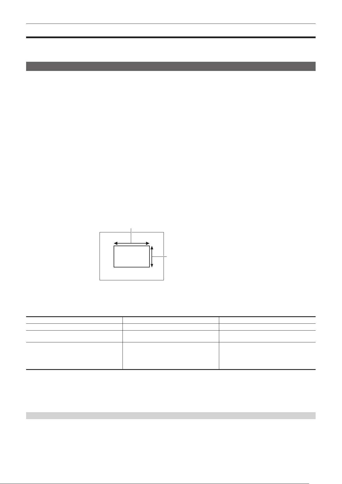
– 121 –
Chapter 5 Shooting — Adjusting the white and black balance
Adjusting the white and black balance
To obtain high-quality video at all times using the camera, the white and black balance must be adjusted according to conditions.
Adjust the AWB (white balance adjustment), ABB (black balance adjustment), and AWB (white balance adjustment) in order to obtain higher image
quality.
White balance adjustment
The white balance must be adjusted again when the lighting conditions change. Follow the steps below to adjust the white balance automatically.
r When storing in <A> of the <WHITE BAL> switch
1
Switch to manual mode with the <AUTO/MANUAL> switch. (page 116)
2
Set the <GAIN> switch.
Normally, set this to 0 dB. If it is too dark, set the gain to an appropriate value.
3
Set the <WHITE BAL> switch to <A>.
4
Change the <ND FILTER> switch settings according to the light conditions.
For setting examples for the <ND FILTER> switch, refer to “Brightness adjustment” (page 119).
5
Place the white pattern at a point where the light conditions match those for the light source for the subject, and zoom in on the
white pattern so that the white color appears in the screen.
6
Adjust the lens aperture.
Adjust the iris so that the brightness of Y GET is approx. 70%.
7
Press the <AWB> button.
White balance is automatically adjusted.
r White pattern
f A white object (cloth or wall) near the subject may also be used for the white pattern.
f Required size of white pattern is as follows.
1/2 or more of the screen width
1/2 or more of the screen height
f Keep bright spotlights out of the screen.
f The white pattern must be placed at the center of the screen.
r Messages displayed in the viewnder and LCD monitor
f When the auto tracking white balance (ATW) function is operating, white balance cannot be adjusted.
Status Message Remark
During adjustment [AWB A ACTIVE]
Adjustment completed [AWB A OK 3200K]
f The adjusted value is automatically stored in the
specied memory (A or B).
When the color temperature of the subject is lower
than 2000 K or higher than 15000 K
[AWB NG <COLOR TEMP LOW>]
[AWB NG <COLOR TEMP HIGH>]
f [AWB NG <COLOR TEMP LOW>] indicates
that the temperature is lower than the displayed
temperature. [AWB NG <COLOR TEMP HIGH>]
indicates that the temperature is higher than the
displayed color temperature.
r [COLOR TEMP Ach SETTING]/[COLOR TEMP Bch SETTING] setting
f The color hue can be changed after the white balance has been adjusted automatically, after setting each item in the [SCENE FILE] menu → [COLOR
TEMP Ach SETTING]/[COLOR TEMP Bch SETTING].
f Adjusting either one of [COLOR TEMP], [R GAIN], [B GAIN], and [G AXIS] changes the other three values.
f Performing the automatic white balance again resets [COLOR TEMP], [R GAIN], [B GAIN], and [G AXIS].
When having no time to adjust the white balance
Set the <WHITE BAL> switch to <PRST>.
f [3200K], [5600K], and the values set in the [CAMERA] menu → [SW MODE] → [W.BAL VAR] toggle in order each time the <AWB> button is pressed.
When [VAR] is selected, turning the multidial can set any white balance value between [2000K] and [15000K].
f The value displayed as [VAR] is not always assured. Use it as a reference value.

– 122 –
Chapter 5 Shooting — Adjusting the white and black balance
When the white balance has not been automatically adjusted
When the white balance has not been successfully adjusted, an error message is displayed on the viewnder screen and LCD monitor displays.
Error message Meaning Remedy
[AWB NG <LOW LIGHT>] There is insufcient light. Increase the amount of light or increase gain.
[AWB NG <LEVEL OVER>] There is too much light. Decrease the amount of light or decrease gain.
[AWB NG <COLOR TEMP LOW>] or [AWB NG
<COLOR TEMP HIGH>]
The color temperature is too high, or too low. Use the appropriate lter or light source.
Manual setting of color temperature
The color temperature of white balance can be adjusted by the setting menu.
1
Press the <AWB> button to select the [W.BAL VAR] mode.
2
In the [CAMERA] menu → [SW MODE] → [W.BAL VAR], set the color temperature.
This can be set from [2000K] to [15000K].
@
NOTE
t The color temperature can also be operated by the multidial button. For details, refer to “Setting the variable value for the white balance” (page 144).
Viewnder and LCD monitor screen displays relating to white balance
For details, refer to “Screen status display” (page 160).
Settings of the auto tracking white balance (ATW) function
The camera is equipped with the Auto Tracking White Balance (ATW) function that automatically tracks the white balance of images according to the
lighting conditions.
The auto tracking white balance function can be assigned to <A>, <B>, and <PRST> of the <WHITE BAL> switch. Set the function with the [CAMERA]
menu → [SW MODE] → [ATW].
Note that if the auto tracking white balance function is assigned to the USER button, the function follows the operation of the USER button.
For details, refer to “Assigning function to the USER buttons” (page 52).
Canceling the auto tracking white balance
Press again the USER button to which the auto tracking white balance function is assigned, touch the USER button icon again, or change the position of
the <WHITE BAL> switch. Note that if the auto tracking white balance function is set to the <WHITE BAL> switch, the function cannot be canceled with
the USER button.
@
NOTE
t This function does not guarantee 100% accuracy for the white balance. Note that the tracking performance relative to changes in ambient lighting and
white balance performance has been given a certain degree of latitude.
Black balance adjustment
Black balance must be adjusted in the following instances:
f When the camera is used for the rst time
f When used after a long period of time without use
f When the ambient temperature has changed considerably
f When super gain is set with the USER button
f When changing the gain switch values
f When toggling items in the [SYSTEM] menu → [REC FORMAT].
To shoot optimum video, we recommend adjusting the black balance immediately before shooting.
Before adjusting the black balance, prepare the conditions for adjusting the white balance.
1
Switch to manual mode with the <AUTO/MANUAL> switch. (page 116)
2
Set the <WHITE BAL> switch to <A> or <B>.
3
Press and hold the <AWB> button for approximately two seconds.
Black balance is adjusted after the white balance.
r Messages displayed in the viewnder and LCD monitor
Status Message Remark
During adjustment [ABB ACTIVE] —
Adjustment completed [ABB OK]
f The adjusted value is automatically stored in
memory.
@
NOTE
t During black balance adjustment, the aperture is set to automatically shut out light.
t During recording, black balance cannot be adjusted.
t Video is not recorded to the memory card even if the REC button is pressed while executing the automatic black balance.

– 123 –
Chapter 5 Shooting — Adjusting the white and black balance
t The gain switching circuit is automatically switched during black balance adjustment. Flicker or noise sometimes appears on the viewnder screen and
LCD monitor. This is not a malfunction.
Black balance memory
Values stored to memory are saved even if the camera is turned off.
– 124 –
Chapter 5 Shooting — Using the zoom function
Using the zoom function
Adjust the angle of view you want to shoot.
The camera has a 20x optical zoom.
This can be expanded up to approximately 32 times (approximately 24 times in UHD recording) when the [CAMERA] menu → [SW MODE] → [i.ZOOM]
→ [ON] is set.
The zoom ratio can be conrmed between [Z000]/[iZ000] (maximum wide angle) to [Z999]/[iZ999] (maximum telephoto) on the screen display. The value
becomes higher as the the camera zooms in and smaller as the camera zooms out.
The zoom ratio is displayed as [iZ000] to [iZ999] when [i.ZOOM] is set to [ON]. Background of the character “i” is displayed in white when the i.ZOOM
function is enabled.
The zoom can be operated at the following three locations:
f Zoom lever (on the grip)
f Zoom lever (on the handle)
f Zoom ring on the lens
Adjusting the zoom position
Adjust the zoom with the zoom lever.
<T>: Zoom in the image.
<W>: Zoom out the image.
Lightly pressing the zoom lever on the grip will operate the zoom at low speed. Pressing strongly will operate the zoom at high speed.
You can also operate the zoom manually with the zoom ring.
Zoom lever (on the handle)
Zoom ring Zoom lever (on the grip)
@
NOTE
t Press the USER button to which [FAST ZOOM] is assigned in the [CAMERA] menu → [USER SW] or touch the USER button icon to enable/disable
[FAST ZOOM] when you want to operate the zoom at a higher speed.
t When [FAST ZOOM] is enabled, the motorized zoom can operated with higher speed if the zoom lever is pushed to the end. However, the zoom
sound becomes louder than usual. Disable [FAST ZOOM] if the sound of the motorized zoom is obtrusive.
r Using the zoom lever on the handle
Performs the zoom operation with the speed set in the [CAMERA] menu → [SW MODE] → [H.ZOOM SPEED].

– 125 –
Chapter 5 Shooting — Image quality adjustment
Image quality adjustment
The image quality of the video to record can be set in the [SCENE FILE] menu. Measurement equipment such as a vector scope is necessary to change
“Advanced settings”.
Detail function
This function thickens or weakens the outlines of images. It effectively softens or sharpens images, but in some cases, the whole image may become
rough due to emphasized noise and edges. To avoid such problems, it is necessary not to add this effect on parts where emphasizing is not needed and
keep the details of the parts.
r General settings
[MASTER DTL]: Sets the level of the detail effect as a whole.
[DTL CORING]: Sets the level of signal (including noise) so that the detail effect does not activate.
r Advanced settings
Set with the [SCENE FILE] menu → [DETAIL SETTING].
[DETAIL]: Sets [ON]/[OFF] of the detail function.
[V.DTL LEVEL]: Sets the intensity of the detail level in the vertical direction.
[DTL FREQ.]: Sets the thickness of the detail.
[LEVEL DEPEND.]: Compresses details in the darker areas when the detail of luminosity signal is emphasized. Details of bright areas are also
compressed more when the value set for [LEVEL DEPEND.] is larger.
[KNEE APE LVL]: Sets the detail level of high luminosity areas (high-brightness areas).
[DTL GAIN(+)]: Sets the detail level of the + direction (to make brighter).
[DTL GAIN(−)]: Sets the detail level of − direction (to make darker).
Skin tone function
This function makes human skin look smoother in images.
R-Y
0
255
255
R
Mg
B
G
Cy
Yl
B-Y/0°
Q axis
I axis
Fig. 1
[I CENTER]
[Q WIDTH]
[Q PHASE]
[I WIDTH]
r General settings
[SKIN TONE DTL A]/[SKIN TONE DTL B]/[SKIN TONE DTL C]: Selects the skin color where the skin tone detail function should operate from three
types of data: [SKIN TONE DTL A]/[SKIN TONE DTL B]/[SKIN TONE DTL C]. [SKIN TONE DTL A]/[SKIN TONE DTL B]/[SKIN TONE DTL C] can be set
independently or in combination.
[SKIN TONE ZEBRA]: Displays the zebra pattern in the selected skin color eld when [SKIN TONE DTL A]/[SKIN TONE DTL B]/[SKIN TONE DTL C]
are enabled. The zebra pattern displays the area selected in [SKIN TONE DTL SETTING].
r Advanced settings
Set with the [SCENE FILE] menu → [SKIN TONE DTL SETTING].
[DETECT TABLE]: Selects the skin color table of the object on which the skin tone table is applied.
[SKIN DTL EFFECT]: Sets the effect level of the skin tone detail.
f The color composition of video signal (R/G/B) can be converted to color difference signal (R-Y/B-Y) as in (Fig. 1). Within those ranges, set the area on
which the following skin tone is applied, using the axis across red and cyan (I axis) and the axis across green and magenta (Q axis).
[I CENTER]: Sets the center position on the I axis (the area where the skin tone applied).
[I WIDTH]: Sets the area width where the skin tone is applied, along the I axis with [I CENTER] in the center.
[Q WIDTH]: Sets the area width where the skin tone is applied, along the Q axis with [I CENTER] in the center.
[Q PHASE]: Sets the phase where the skin tone is applied, with the Q axis being the reference.
RB gain control function
This function makes settings to add or reduce the intensity of red and blue colors according to the position of the <WHITE BAL> switch.
The function works when the switch is at the <PRST> position or when automatic white balance is active. It does not work when auto tracking white
balance is activated.
– 126 –
Chapter 5 Shooting — Image quality adjustment
r General settings
Use the camera with the factory settings.
r Advanced settings
Set with the [SCENE FILE] menu → [RB GAIN CONTROL SETTING].
f When the <WHITE BAL> switch is at the <PRST> position
[R GAIN AWB PRE]: Sets to add or reduce the intensity of the red color.
[B GAIN AWB PRE]: Sets to add or reduce the intensity of the blue color.
f When the <WHITE BAL> switch is at the <A> position
[R GAIN AWB A]: Sets to add or reduce the intensity of the red color.
[B GAIN AWB A]: Sets to add or reduce the intensity of the blue color.
f When the <WHITE BAL> switch is at the <B> position
[R GAIN AWB B]: Sets to add or reduce the intensity of the red color.
[B GAIN AWB B]: Sets to add or reduce intensity of the blue color.
f When performing automatic white balance by setting the <WHITE BAL> switch to the <A> position
[AWB A GAIN OFFSET]: Sets whether to keep or reset the values set for [R GAIN AWB A] and [B GAIN AWB A].
f When performing automatic white balance by setting the <WHITE BAL> switch to the <B> position
[AWB B GAIN OFFSET]: Sets whether to keep the values set for [R GAIN AWB B] and [B GAIN AWB B] or reset them.
Chroma setting function
This function sets color saturation and phase. It applies effects on whole images. It cannot be set to individual color hue.
r General settings
[CHROMA LEVEL]: Sets the chroma level of the P
R
signal and P
B
signal. When the vector scope is used, the distance from the center (no color) is
increased or decreased for the entire image.
[CHROMA PHASE]: Finely adjusts the chroma phase of the P
R
signal and P
B
signal. When the vector scope is used, the whole image rotates clockwise
or counter-clockwise.
r Advanced settings
No setting items are provided.
Matrix function
This function sets the image color representation by selecting the matrix table. If the settings are changed, the representation of all the colors in the
image will also be changed.
The change in color against each axis of matrix is as following gure.
f The bold line in the gure is the reference line for each axis of matrix. The color above the bold line does not change.
R Mg
G Cy
BYl
R Mg
G Cy
BYl
R Mg
G Cy
BYl
R Mg
G Cy
BYl
R Mg
G Cy
BYl
R Mg
G Cy
BYl
(R‑G)
(R‑G)
(G‑B)
(G‑B)
(B‑R)
(B‑R)
(R‑B)
(G‑R)
(G‑R)
(B‑G)
(B‑G)
(R‑B)
r General settings
[MATRIX TYPE]: Selects the matrix table to represent the color for shooting.
r Advanced settings
Set with the [SCENE FILE] menu → [MATRIX SETTING].

– 127 –
Chapter 5 Shooting — Image quality adjustment
Performs ne adjustment relatively on the matrix table selected in [MATRIX TYPE].
Since the ne adjustment is performed relatively, if the matrix table selected in [MATRIX TYPE] differs, the color representation may differ even when
the same value is set.
[ADAPTIVE MATRIX]: Controls the color collapse under intense blue light source.
Color correction function
This function sets color saturation and phase. These settings affect each of the 16 phases of the video individually. It can be set to individual color hue.
R
Mg
G
Cy
B
Yl
P10
P9
P8
P7P6
P5
P4
P3
P2
P1
SAT(‑)
PHASE(+)
R: Red
P1: (Yl‑R)‑R
P2: (Yl‑R)
P3: Yl‑(Yl‑R)
YI: Yellow
P4: (G‑Yl)‑Yl
P5: (G‑Yl)
G: Green
P6: (Cy‑G)
Cy: Cyan
P7: (B‑Cy)
B: Blue
P8: (Mg‑B)
Mg: Magenta
P9: (R‑Mg)
P10: R‑(R‑Mg)
(‑)
(+)
(Axis to operate)
r General settings
Use the camera with the factory settings.
r Advanced settings
[R] ([PHASE])/[R-R-Mg] ([PHASE])/[R-Mg] ([PHASE])/[Mg] ([PHASE])/[Mg-B] ([PHASE])/[B] ([PHASE])/[B-Cy] ([PHASE])/[Cy] ([PHASE])/[Cy-G]
([PHASE])/[G] ([PHASE])/[G-Yl] ([PHASE])/[G-Yl-Yl] ([PHASE])/[Yl] ([PHASE])/[Yl-Yl-R] ([PHASE])/[Yl-R] ([PHASE])/[Yl-R-R] ([PHASE]): Changes
the phases. + rotates clockwise and − rotates counter-clockwise.
[R] ([SAT])/[R-R-Mg] ([SAT])/[R-Mg] ([SAT])/[Mg] ([SAT])/[Mg-B] ([SAT])/[B] ([SAT])/[B-Cy] ([SAT])/[Cy] ([SAT])/[Cy-G] ([SAT])/[G] ([SAT])/[G-Yl]
([SAT])/[G-Yl-Yl] ([SAT])/[Yl] ([SAT])/[Yl-Yl-R] ([SAT])/[Yl-R] ([SAT])/[Yl-R-R] ([SAT]): Changes the saturation.
Black control function
This function sets the black level that is to be the reference of luminance.
r General settings
[MASTER PED]: Sets the reference black level. RGB also changes by changing this setting. − makes the black color darker, and + makes it less dark.
r Advanced settings
Set with the [SCENE FILE] menu → [RGB BLACK CONTROL SETTING].
[R PED]: Sets the pedestal level of Rch.
[G PED]: Sets the pedestal level of Gch.
[B PED]: Sets the pedestal level of Bch.
[PEDESTAL OFFSET]: Sets whether to keep the values set for each item of [R PED], [G PED], and [B PED] or reset them when automatic black
balance adjustment is performed.
Gamma function
This function optimizes the tone of images.
r General settings
[GAMMA MODE SEL]: Selects a gamma mode from eight types.
r Advanced settings
Set with the [SCENE FILE] menu → [GAMMA SETTING].
[MASTER GAMMA]: Sets the master gamma in 0.01 steps.
f When [FILM-REC] is selected in [GAMMA MODE SEL]
[F-REC DYNAMIC LVL]: Sets dynamic range.
[F-REC BLACK STR LVL]: Sets black stretch.
f When [VIDEO-REC] is selected in [GAMMA MODE SEL]
[V-REC KNEE SLOPE]: Sets knee slope.
[V-REC KNEE POINT]: Sets knee point.
[BLACK GAMMA]: Sets the gamma curve compression and expansion of dark areas.
[B.GAMMA RANGE]: Sets the maximum level to perform compression/expansion.

– 128 –
Chapter 5 Shooting — Image quality adjustment
Knee function
This function sets the compression of video signals to prevent halation in images.
r General settings
Use the camera with the factory settings.
r Advanced settings
Set with the [SCENE FILE] menu → [KNEE SETTING].
[KNEE MODE]: Sets the operation mode of knee function ([AUTO]/[MANUAL]/[OFF]).
f When [AUTO] is selected in [KNEE SETTING]
[A.KNEE RESPONSE]: Sets the speed of response. The smaller the setting value, the faster the response speed is.
f When [MANUAL] is selected in [KNEE SETTING]
[KNEE POINT]: Sets the knee point position in 0.5% steps.
[KNEE SLOPE]: Sets the knee inclination.
White clip function
This function sets the brightest part of video signals to be not brighter than a certain level.
r General settings
Use the camera with the factory settings.
r Advanced settings
Set with the [SCENE FILE] menu → [WHITE CLIP SETTING].
[WHITE CLIP]: Turns the white clip function [ON]/[OFF]. This enables the [WHITE CLIP LEVEL] setting value when the function is [ON].
[WHITE CLIP LEVEL]: Sets the white clip level.

– 129 –
Chapter 5 Shooting — Variable frame rate (VFR) recording function/super slow recording function
Variable frame rate (VFR) recording function/super slow recording function
It is possible to acquire smooth slow motion or quick motion vide by shooting with a different frame rate from the frame rate to play back.
Variable frame rate (VFR)
Allows the high-speed shooting from 1fps to maximum of 60fps.
1
In the [SYSTEM] menu → [FREQUENCY]/[FILE FORMAT]/[REC FORMAT], select the resolution and codec for recording video and
the frequency for the reference frame rate.
f For the combinations that can be set, refer to “Selecting the resolution, codec, and frame rate for recording video” (page 117).
The range of the frame rate that can perform high-speed shooting differs depending on the setting.
2
Select the [SCENE FILE] menu → [VFR] → [ON].
f This can also be set even with the USER button. Refer to “Functions assigned to USER buttons” (page 52).
3
Set the frame rate in accordance with the shooting condition in the [SCENE FILE] menu → [FRAME RATE].
f This can also be set with the multi manual function. Refer to “Multi manual function” (page 144).
4
Press the REC button.
Variable frame rate recording is started.
Super slow
This allows high-speed shooting of 120fps/100fps.
1
In the [SYSTEM] menu → [FREQUENCY]/[FILE FORMAT]/[REC FORMAT], select the resolution and codec for recording video and
the frequency for the reference frame rate.
f For the combinations that can be set, refer to “Selecting the resolution, codec, and frame rate for recording video” (page 117).
2
Select the [SYSTEM] menu → [SUPER SLOW] → [ON].
f This can also be set even with the USER button.
Refer to “Functions assigned to USER buttons” (page 52).
3
Press the REC button.
Super slow recording starts.
@
NOTE
t Audio cannot be recorded with the variable frame rate recording and super slow recording. However, audio is also recorded if the frame rate same as
the recording frame frequency of [REC FORMAT] is set when using variable frame rate recording.
t The screen may be disrupted or become dark when the frame rate setting is changed.
t The frame rate cannot be changed while recording.
t The [RECORDING] menu → [TC/UB] → [FREE/REC RUN] is xed to [REC RUN].
t The recording is paused when ten hours has past from the time the recording was started. The recording is automatically resumed after few seconds.
When performing high-speed shooting, the recording time will be shorter than 10 hours depending on the ratio of the frame rate of the recording
format and the variable frame rate. The recording will stop in 5 hours when the recording frame frequency of [REC FORMAT] is set to 23.98p and the
[SCENE FILE] menu → [FRAME RATE] is set to [48fps].
t For recording limitations of variable frame rate recording or super slow recording, refer to “Recording function that cannot be used simultaneously”
(page 198).
t It may take time to stop recording even if recording is stopped right after recording is started.
When the recording frame frequency of [REC FORMAT] is set to 59.94p and the [SCENE FILE] menu → [FRAME RATE] is set to [1fps], recording is
continued for a maximum of one minute until the length of the clip after shooting becomes one second.
– 130 –
Chapter 5 Shooting — Audio input
Audio input
The camera can record four channels of audio.
(However, two channels when AVCHD is selected as the recording le format)
The audio to input to each channel can be switched to the built-in microphone, an external microphone, or a connected audio device.
Switching the audio input
r Audio recording format
The audio recording format such as compression format varies depending on the recording mode.
Recording mode Recording format Sampling rate/bit
P2 Linear PCM (LPCM) 48 kHz/24 bit*
MOV Linear PCM (LPCM) 48 kHz/24 bit
AVCHD Dolby Audio
TM
48 kHz/16 bit
* When the [REC FORMAT] is set to following, it will be 48 kHz/16 bit.
[1080-59.94p/AVC-G12]
[1080-50.00p/AVC-G12]
[1080-59.94i/AVC-G12]
[1080-50.00i/AVC-G12]
[720-59.94p/AVC-G12]
[720-50.00p/AVC-G12]
r Selecting audio input signals
Selects the audio signal to record in the audio channel 1/audio channel 2.
Audio signal to record in the audio channel 3/audio channel 4 is automatically set with the settings of the <CH1 SELECT> switch and the <CH2
SELECT> switch.
Item Input signal to be recorded
<CH1 SELECT> <CH2 SELECT> Audio channel 1 Audio channel 2 Audio channel 3 Audio channel 4
<INT(L)> <INT(R)> Built-in microphone <L> Built-in microphone <R> <AUDIO INPUT 1>
terminal
<AUDIO INPUT 2>
terminal
<INPUT1> Built-in microphone <L> <AUDIO INPUT 1>
terminal
<AUDIO INPUT 1>
terminal
Built-in microphone <R>
<INPUT2> Built-in microphone <L> <AUDIO INPUT 2>
terminal
<AUDIO INPUT 1>
terminal
Built-in microphone <R>
<INPUT1> <INT(R)> <AUDIO INPUT 1>
terminal
Built-in microphone <R> Built-in microphone <L> <AUDIO INPUT 2>
terminal
<INPUT1> <AUDIO INPUT 1>
terminal
<AUDIO INPUT 1>
terminal
Built-in microphone <L> Built-in microphone <R>
<INPUT2> <AUDIO INPUT 1>
terminal
<AUDIO INPUT 2>
terminal
Built-in microphone <L> Built-in microphone <R>
<INPUT2> <INT(R)> <AUDIO INPUT 2>
terminal
Built-in microphone <R> Built-in microphone <L> <AUDIO INPUT 2>
terminal
<INPUT1> <AUDIO INPUT 2>
terminal
<AUDIO INPUT 1>
terminal
Built-in microphone <L> Built-in microphone <R>
<INPUT2> <AUDIO INPUT 2>
terminal
<AUDIO INPUT 2>
terminal
Built-in microphone <L> Built-in microphone <R>
When using the built-in microphone
1
Set the <CH1 SELECT> switch to the <INT(L)> position.
The audio signal of the built-in microphone <L> is recorded in the audio channel 1.
2
Set the <CH2 SELECT> switch to the <INT(R)> position.
The audio signal of the built-in microphone <R> is recorded in the audio channel 2.
@
NOTE
t To decrease the wind noise of the microphone, select the [AUDIO] menu → [REC CH SETTINGS] → [CH1 MIC LOWCUT]/[CH2 MIC LOWCUT]/[CH3
MIC LOWCUT]/[CH4 MIC LOWCUT] → [ON].
When using an audio device or an external microphone
1
Connect an audio device or an external microphone to the <AUDIO INPUT 1>/<AUDIO INPUT 2> terminal.
2
Switch the connected audio input with the <INPUT1>/<INPUT2> switch.
Connected device
Menu settings (you can set each channel individually)
<INPUT1>/<INPUT2>
[INPUT1 MIC LEVEL]/[INPUT2 MIC
LEVEL]*
1
[INPUT1 LINE LEVEL]/[INPUT2 LINE
LEVEL]*
2
Audio device <LINE> Disabled [4dB], [0dB]

– 131 –
Chapter 5 Shooting — Audio input
Connected device
Menu settings (you can set each channel individually)
<INPUT1>/<INPUT2>
[INPUT1 MIC LEVEL]/[INPUT2 MIC
LEVEL]*
1
[INPUT1 LINE LEVEL]/[INPUT2 LINE
LEVEL]*
2
External microphone <MIC>
[−40dB], [−50dB], [−60dB]
Disabled
External microphone (with power
supply)
<+48V> [−40dB], [−50dB], [−60dB]
Disabled
*1 Factory setting: [−50dB]
*2 Factory setting: [0dB]
@
NOTE
t When using a super-directional microphone AG-MC200G (optional), set [INPUT1 MIC LEVEL]/[INPUT2 MIC LEVEL] to [−50dB].
Adjusting the audio recording level
There are manual adjustment and automatic adjustment as the adjustment method of the audio recording level.
Automatic adjustment of the recording level
1
Select the [AUDIO] menu → [REC CH SETTINGS] → [CH1 LEVEL]/[CH2 LEVEL]/[CH3 LEVEL]/[CH4 LEVEL] → [AUTO].
f Audio channel 1 to audio channel 4 can be individually set.
f Following settings are disabled when the [AUDIO] menu → [REC CH SETTINGS] → [CH1 LEVEL]/[CH2 LEVEL] → [AUTO] is selected.
‑ Adjustment of the recording level by the <AUDIO LEVEL CH1>/<AUDIO LEVEL CH2> dial
‑ [AUDIO] menu → [REC CH SETTINGS] → [CH1 LIMITER]/[CH2 LIMITER] setting
f Following settings are disabled when the [AUDIO] menu → [REC CH SETTINGS] → [CH3 LEVEL]/[CH4 LEVEL] → [AUTO] is selected.
‑ [AUDIO] menu → [REC CH SETTINGS] → [CH3 LEVEL CONTROL]/[CH4 LEVEL CONTROL] setting
‑ [AUDIO] menu → [REC CH SETTINGS] → [CH3 LIMITER]/[CH4 LIMITER] setting
Manual adjustment of the recording level
r Audio channel 1/audio channel 2 settings
1
Select the [AUDIO] menu → [REC CH SETTINGS] → [CH1 LEVEL]/[CH2 LEVEL] → [MANUAL].
2
Adjust the recording level with the <AUDIO LEVEL CH1>/<AUDIO LEVEL CH2> dial.
f When the input level of audio exceeds 0 dB, the level display exceeding 0 dB is displayed in red in the camera image screen and the audio level
meter in the AUDIO screen of the the mode check. This is indicating that the input volume is too high.
Adjust so that the maximum value of the audio level does not exceed 0 dB.
r Audio channel 3/audio channel 4 settings
1
Select the [AUDIO] menu → [REC CH SETTINGS] → [CH3 LEVEL]/[CH4 LEVEL] → [MANUAL].
2
Adjust the recording level with the [AUDIO] menu → [REC CH SETTINGS] → [CH3 LEVEL CONTROL]/[CH4 LEVEL CONTROL].
The larger the value, the larger the level.
@
NOTE
t Following setting is enabled when the [AUDIO] menu → [REC CH SETTINGS] → [CH1 LEVEL]/[CH2 LEVEL]/[CH3 LEVEL]/[CH4 LEVEL] →
[MANUAL] is selected.
‑ [AUDIO] menu → [REC CH SETTINGS] → [CH1 LIMITER]/[CH2 LIMITER]/[CH3 LIMITER]/[CH4 LIMITER] setting
Recording standard level
The recording standard level can be set.
1
Select the [AUDIO] menu → [REC CH SETTINGS] → [HEAD ROOM] → [12dB]/[18dB]/[20dB].
[20dB]: Select this when matching the recording standard level with the Panasonic broadcasting AJ series camera.
[12dB]: Select this when matching the recording standard level with the Panasonic professional AG-UX series camera.
Conrming the audio input level
The input level of the audio can be conrmed in the camera image screen and the AUDIO screen of the mode check.
Monitoring the audio
Audio recorded with the camera can be heard with a speaker or headphones.
Audio is not output from the speaker during shooting.
Setting the output audio
Sets the audio channel and the format to be output from the headphone terminal.
1
Select the [AUDIO] menu → [OUTPUT SETTINGS] → [AUDIO OUT].
2
Select the type of audio.
[CH1]: Outputs the signal for audio channel 1 as monaural.

– 132 –
Chapter 5 Shooting — Audio input
[CH2]: Outputs the signal for audio channel 2 as monaural.
[CH1/2 STEREO]: Outputs the signals of the audio channel 1 and the audio channel 2 as stereo.
[CH1/2 MIX]: Mixes the signals of the audio channel 1 and the audio channel 2 and outputs as monaural.
[CH3]: Outputs the signal for audio channel 3 as monaural.
[CH4]: Outputs the signal for audio channel 4 as monaural.
[CH3/4 STEREO]: Outputs the signals of the audio channel 3 and the audio channel 4 as stereo.
[CH3/4 MIX]: Mixes the signals of the audio channel 3 and the audio channel 4 and outputs as monaural.
@
NOTE
t The audio channel of the output audio (audio channel 1/2 and audio channel 3/4) is switched while the USER button to which [AUDIO MON SEL] is
assigned is pressed or the USER button icon is touched.
Conrming audio input setting
The setting for the audio input can be conrmed in the AUDIO screen of the mode check.
For details, refer to “Mode check display” (page 166).
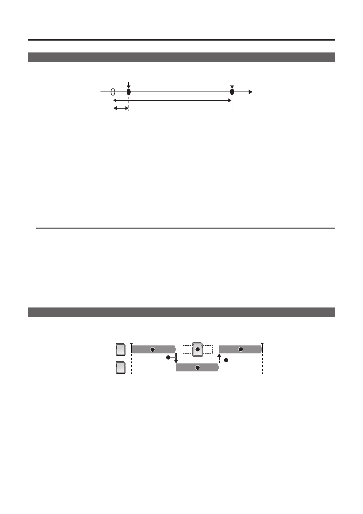
– 133 –
Chapter 5 Shooting — Special recording function
Special recording function
Special recording such as pre-recording or relay recording is possible by setting the menu.
Pre-recording
Records the video and audio from specic time before the operation to start the recording.
Operation to start recording Operation to stop recording
Actual recording time
Pre-recording time
(Time)
The pre-recording time varies depending on the setting of the [SYSTEM] menu → [FILE FORMAT]/[REC FORMAT].
f When [FILE FORMAT] is set to [P2]: Approximately 3 seconds
f When [FILE FORMAT] is set to [MOV], and [REC FORMAT] is set to [2160-29.97p/422ALL-I 400M], [2160-25.00p/422ALL-I 400M], or
[2160-23.98p/422ALL-I 400M]: Approximately 3 seconds
f When [FILE FORMAT] is set to [MOV], and [REC FORMAT] is set to [2160-59.94p/HEVC LongGOP 200M], [2160-59.94p/HEVC LongGOP 100M],
[2160-59.94p/420LongGOP 150M], [2160-50.00p/HEVC LongGOP 200M], [2160-50.00p/HEVC LongGOP 100M], [2160-50.00p/420LongGOP 150M],
[2160-29.97p/HEVC LongGOP 150M], [2160-29.97p/422LongGOP 150M], [2160-29.97p/420LongGOP 100M], [2160-25.00p/HEVC LongGOP 150M],
[2160-25.00p/422LongGOP 150M], [2160-25.00p/420LongGOP100M], [2160-23.98p/HEVC LongGOP 150M], [2160-23.98p/422LongGOP 150M], or
[2160-23.98p/420LongGOP 100M]: Approximately 5 seconds
f When set to other than above: Approximately 10 seconds
1
Select the [RECORDING] menu → [PRE REC] → [ON].
[P] is displayed in the recording status display of the camera image screen.
2
Press the REC button.
@
NOTE
t The video and audio may not be able to record for specic time before in following cases.
‑ Immediately after the power is set to < j > (ON)
‑ Immediately after opening the menu
‑ Immediately after the memory card is inserted
‑ Immediately after playing back the recorded video
‑ Immediately after closing the thumbnail screen
‑ When [ON]/[OFF] are toggled in the [SCENE FILE] menu → [VFR] or [SCENE FILE] menu → [FRAME RATE] is set
‑ During the time from recording stop until completion of writing to the memory card
t When [PRE REC] is set to [ON], the [RECORDING] menu → [TC/UB] → [FREE/REC RUN] is xed to [FREE RUN].
t The pre-recording is canceled once when three hours has past without starting the recording.
t For recording limitations of the pre-recording, refer to “Recording function that cannot be used simultaneously” (page 198).
t Pre-recording cannot be performed if the remaining recording capacity of the memory card is less than one minute.
Relay recording
When inserting memory cards into the two card slots, recording can continue on the second memory card if the remaining recording capacity of the
other memory card is exhausted.
1
13
1
2
2
Card slot 1
Start shooting
Pause
Card slot 2
1 During recording
2 Automatically switch the recording target card slot
3 Replace with a different recordable memory card
1
Select the [RECORDING] menu → [2 SLOTS FUNC.] → [RELAY REC].
[RELAY] is displayed in the two slot function display of the camera image screen.
A slanted line is displayed on the [RELAY] display when the relay recording is not possible, such as when a memory card is not inserted in either of
the two card slots.
2
Press the REC button.
f The recording target switches to another memory card when the remaining recording capacity of one of the memory cards is exhausted during
recording and relay recording starts. The number of the card slot that became the recording target is displayed with black and white inverted.
Recording can be performed on three or more memory cards. Replace the memory card with no more remaining recording capacity after the
recording target has switched.
f To change the recording target card slot before starting the recording, press the <SLOT SEL> button. This will not operate during recording.
– 134 –
Chapter 5 Shooting — Special recording function
@
NOTE
t It may take some time to recognize the memory card when the memory card is inserted. When recording to three or more memory cards by replacing
a memory card while recording, replace the memory card with recording capacity sufciently left on the memory card that is recording.
t The recording target cannot be switched when the remaining recording capacity of the relay memory card is less than one minute.
t The maximum continuous recording time for relay recording is ten hours.
t The recording is stopped once when the recording time of relay recording exceeds ten hours. The recording is automatically resumed after few
seconds.
t For recording limitations of the relay recording, refer to “Recording function that cannot be used simultaneously” (page 198).
Simultaneous recording
Insert memory cards into two card slots to record the same video onto two memory cards.
Card slot 1
Card slot 2
A clip
A clip
Stand-by
Stand-by
B clip
B clip
Start recording
End recording
Start recording
C clip
End recording (no remaining space)
Memory card recording time
1
Select the [RECORDING] menu → [2 SLOTS FUNC.] → [SIMUL REC].
[SIMUL] is displayed in the two slot function display of the camera image screen.
A slanted line is displayed on the [SIMUL] display when simultaneous recording is not possible, such as when a memory card is not inserted in either
of the two card slots.
2
Press the REC button.
f The simultaneous recording will stop when the remaining recording capacity of one of the memory cards is exhausted.
A slanted line is displayed in the [SIMUL] display when simultaneous recording is not possible.
To start the simultaneous recording again, replace the memory card that has run out of the recording capacity with another memory card, and then
press the REC button.
f When the REC button is pressed without replacing the memory card, standard recording is performed to the memory card with remaining recording
capacity.
@
NOTE
t Use of memory cards with the same Speed Class or capacity for simultaneous recording is recommended.
The recording may stop due to insufcient speed when memory cards with different Speed Classes or capacities are used. If the recording is stopped,
the video right before stopping may become invalid recording.
t Start the recording after both of the two memory cards have been recognized. When the recording starts before both memory cards are recognized,
the camera performs standard recording on one of the memory cards that has been recognized. The camera conrms the status of the memory card
every time the recording is completed. If both cards are recognized at that time, it will perform the simultaneous recording from the next recording.
t When recording to one of the memory cards stops due to a recording error during simultaneous recording, recording to the other memory card
continues.
t If there is remaining recording capacity on one of the memory cards after completing the simultaneous recording, the memory card with remaining
recording capacity automatically becomes the recording target. Standard recording will start when the REC button is pressed.
t Standard recording is performed when only one memory card is inserted even if the camera is set to simultaneous recording.
t Once the simultaneous recording is completed, [DEL LAST CLIP] (nal clip delete function) assigned to the USER button will not operate.
t For the folder name and the le name when performing simultaneous recording in MOV format, refer to “Handling the recording data” (page 44).
t For recording limitations of the simultaneous recording, refer to “Recording function that cannot be used simultaneously” (page 198).
– 135 –
Chapter 5 Shooting — Special recording function
Background recording
If the memory cards are inserted into two card slots, set the background recording mode and then press the REC button to start recording
simultaneously on card slot 1 and card slot 2. On card slot 1, recording can be repeatedly started and stopped as necessary by operating the REC
button. On card slot 2, the recording operation continues as background recording.
By performing background recording on card slot 2, you will not miss important scenes while recording is stopped.
For recording limitations of background recording, refer to “Recording function that cannot be used simultaneously” (page 198).
REC REC REC STOP
REC PAUSE
REC
REC PAUSE
Card slot 1
(Main recording)
REC button operations
Button operation for background
recording stop*
Card slot 2
(Background recording)
A clip
A clip
B clip
No remaining space on card slot 1
Continues recording to card slot 2
Stand-by
Memory card recording time
*USER button assigned to [BACKGR PAUSE]
Starting background recording
1
Select the [RECORDING] menu → [2 SLOTS FUNC.] → [BACKGR REC].
[BACKGR] is displayed in the two slot function display of the camera image screen.
A slanted line is displayed on the [BACKGR] display when background recording is not possible, such as when a memory card is not inserted in the
card slot 2.
2
Press the REC button.
Recording starts simultaneously on card slot 1 and card slot 2.
Start or stop recording on card slot 1 with REC button operations.
On card slot 2, the recording operation continues as background recording.
@
NOTE
t Records on both card slot 1 and card slot 2 in the format set in the [SYSTEM] menu.
t Background recording cannot be performed in the following cases.
‑ When the [RECORDING] menu → [REC FUNCTION] → [REC MODE] is set to anything other than [NORMAL]
t The lighting status of the tally lamp changes according to start or stop of recording on card slot 1.
t Time code is xed to free run.
t Control of recording operation of the external equipment (such as recorder) connected to the <SDI OUT> terminal and the <HDMI> terminal is linked
to the start/stop recording of the card slot 1.
t In background recording mode, deleting last clip function is disabled.
t The memory card in card slot 1 can be replaced even while background recording is performed on card slot 2 if recording on card slot 1 is stopped.
t In the background recording mode, standard recording can be performed on card slot 1 if a memory card for recording is not inserted in card slot 2 or
the remaining recording capacity of the memory card in card slot 2 has run out.
Ending background recording
1
Press and hold the USER button to which [BACKGR PAUSE] is assigned for approximately five seconds or touch and hold the
USER button icon for approximately five seconds and release.
The background recording stops on card slot 2.
The background recording on card slot 2 can also be stopped by pressing and holding the <EXIT> button for approximately ve seconds.
@
NOTE
t The background recording on card slot 2 cannot end while recording is performed on card slot 1. End the background recording while recording is
stopped on card slot 1.
t The background recording on card slot 2 ends in the following cases.
‑ When the power is turned off
‑ When the remaining recording capacity of the memory card has run out
‑ When an error has occurred when writing to the memory card

– 136 –
Chapter 5 Shooting — Special recording function
Interval recording
The camera will record one frame at each set time interval.
1 frame recording 1 frame recording 1 frame recording
(Time)
Time set in [INTERVAL TIME] Time set in [INTERVAL TIME]
1
Select the [RECORDING] menu → [REC FUNCTION] → [REC MODE] → [INTERVAL].
[INTRVL] is displayed in the special recording function display of the camera image screen.
f This cannot be selected when the recording mode is set to AVCHD.
2
Set the time in the [RECORDING] menu → [REC FUNCTION] → [INTERVAL TIME].
3
Press the REC button.
f [I-REC] is displayed in red in the special recording function display of the camera image screen.
f The camera will repeat the operation of one frame recording at set time interval.
f To stop recording, press the REC button.
f Set [NORMAL] in the [RECORDING] menu → [REC FUNCTION] → [REC MODE] to clear the setting.
f Set whether to keep the settings after turning off the power in the [RECORDING] menu → [REC FUNCTION] → [REC MODE HOLD].
@
NOTE
t Audio is not recorded.
t Recorded data (data recorded until recording was stopped) is included in one clip.
t The [RECORDING] menu → [TC/UB] → [FREE/REC RUN] is xed to [REC RUN].
t The [RECORDING] menu → [TC/UB] → [DF/NDF] is xed to [NDF].
t [SDI REC REMOTE] and [HDMI REC REMOTE] will not operate.
t If the length of the clip is less than three seconds when the recording is stopped, the image of the nal frame will be recorded to make the length of the
clip to three seconds.
t The recording is stopped once when the length of the clip exceeds ten hours in the interval recording. The recording is automatically resumed after
few seconds.
t For recording limitations of the interval recording, refer to “Recording function that cannot be used simultaneously” (page 198).
IR recording
A night time shooting using the IR light can be performed.
r Assigning [IR REC] to the USER button
1
Select the [CAMERA] menu → [USER SW] → [USER1] to [USER12] → [IR REC].
Set so enable/disable of the IR recording can be switched with an arbitrary USER button.
r Performing IR recording
1
Press the USER button to which [IR REC] is assigned or touch the USER button icon.
The camera will enter the IR recording mode.
2
Press the REC button.
IR recording is started.
@
NOTE
t This can also be set with the [CAMERA] menu → [SW MODE] → [IR REC].
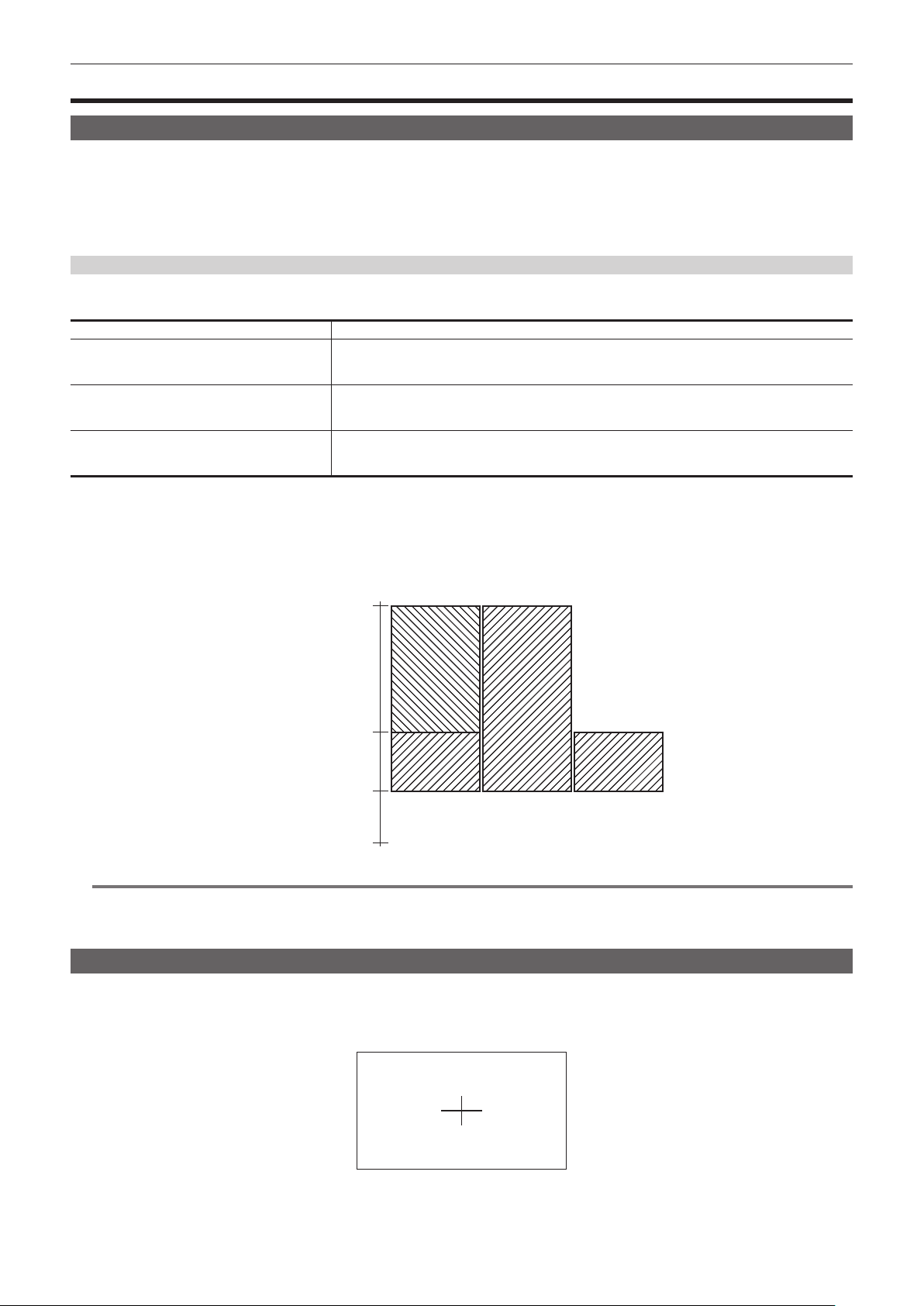
– 137 –
Chapter 5 Shooting — Convenient shooting functions
Convenient shooting functions
Zebra patterns display
The camera can display two types of zebra patterns to the output image from the LCD monitor.
1
Select the [VIDEO OUT/LCD/VF] menu → [EI ASSIST] → [ZEBRA] → [ON].
f Select [MOMENT]. The zebra pattern is displayed for approximately ve seconds when the the USER button to which [ZEBRA] is assigned is
pressed or the USER button icon is touched.
f Factory setting: [OFF]
Setting the detection level
1
Set each item in the [VIDEO OUT/LCD/VF] menu → [EI ASSIST].
Item Description of settings
[ZEBRA1 DETECT] Sets the detection level of zebra pattern 1.
[0%]…[109%]
(Factory setting: [80%])
[ZEBRA2 DETECT] Sets the detection level of zebra pattern 2.
[0%]…[109%]
(Factory setting: [100%])
[ZEBRA2] Enables/disables zebra pattern 2 and selects [SPOT].
[ON], [SPOT], [OFF]
(Factory setting: [OFF])
r Display area of the zebra pattern
The display area of the zebra pattern varies depending on the [VIDEO OUT/LCD/VF] menu → [EI ASSIST] setting.
When [SPOT] is selected in [ZEBRA2], the area corresponding to the [ZEBRA1 DETECT] setting value to the [ZEBRA2 DETECT] setting value is
displayed in zebra pattern.
[ZEBRA2]
[ON] [OFF] [SPOT]
[109%]
[ZEBRA2 DETECT]
[ZEBRA1 DETECT]
[0%]
@
NOTE
t The zebra pattern cannot be recorded.
t The zebra pattern is not displayed while displaying the color bars.
The zebra pattern is not displayed when the [SCENE FILE] menu → [GAMMA MODE SEL] → [HLG] is selected.
Displaying the center marker
A center marker can be displayed.
1
Select the type of the center marker in the [VIDEO OUT/LCD/VF] menu → [MARKER] → [CENTER MARKER].
f The center marker is not displayed when [OFF] is selected.

– 138 –
Chapter 5 Shooting — Convenient shooting functions
Displaying the safety zone marker
A safety zone marker can be displayed.
1
Select the type of the frame in the [VIDEO OUT/LCD/VF] menu → [MARKER] → [SAFETY MARKER].
f The safety zone marker is not displayed when [OFF] is selected.
Setting the size of the frame.
1
Select the size of the frame in the [VIDEO OUT/LCD/VF] menu → [MARKER] → [SAFETY AREA].
Displaying frame marker
A frame marker can be displayed.
1
Select the angle of the view in the [VIDEO OUT/LCD/VF] menu → [MARKER] → [FRAME MARKER].
f The frame marker is not displayed when [OFF] is selected.
@
NOTE
t This is xed to [OFF] when the [SYSTEM] menu → [REC FORMAT] → [480-59.94i/AVCHD SA]/[576-50.00i/AVCHD SA] and the [SYSTEM] menu →
[ASPECT] → [4:3] are set.
Setting the display color
1
Select the display color in the [VIDEO OUT/LCD/VF] menu → [MARKER] → [FRAME COLOR].
@
NOTE
t The marker cannot be recorded.
t The marker is not displayed while displaying the color bars when the enlarged display function of the focus assist function is enabled.
Focus assist function
The focus assist function enables you to focus the target easily.
The recording image on the LCD monitor and the viewnder can be displayed enlarged, or the focused area can be visually enhanced.
Enlarged display function
Center of the recording image is displayed enlarged to make it easier to focus.
To enable the enlarged display function, press the <FOCUS ASSIST> button, press the USER button to which [EXPAND] is assigned, or touch the
USER button icon.
When enabling the enlarged display function by pressing the <FOCUS ASSIST> button
r Assigning [EXPAND] to the <FOCUS ASSIST> button
Set to enable/disable the enlarged display function by toggling the setting with the <FOCUS ASSIST> button.
1
Select the [VIDEO OUT/LCD/VF] menu → [FOCUS ASSIST] → [FOCUS ASSIST SW] → [EXPAND].
r Using the enlarged display function
1
Press the <FOCUS ASSIST> button.
Press the <FOCUS ASSIST> button again to return to the normal display.
When enabling the enlarged display function by pressing the USER button or touching the USER button icon
r Assigning [EXPAND] to the USER button
Set so enable/disable of the enlarged display function can be switched with an arbitrary USER button.
1
Select the [CAMERA] menu → [USER SW] → [USER1] to [USER12] → [EXPAND].
r Using the enlarged display function
1
Press the USER button to which [EXPAND] is assigned or touch the USER button icon.
Press the USER button or touch the USER button icon again to return to the normal display.
Pressing the <EXIT> button also returns to the normal display.
Setting the mode for enlarged display function
1
Select the mode for the enlarged display function in the [VIDEO OUT/LCD/VF] menu → [FOCUS ASSIST] → [EXPAND MODE].
[10SEC]: Disables the enlarged display function after ten seconds have elapsed.
[HOLD]: Enables the enlarged display function until the <FOCUS ASSIST> button assigned to [EXPAND] or the USER button is pressed or the
USER button icon is touched again.
[UNTIL REC]: Enables the enlarged display function until starting the recording operation.
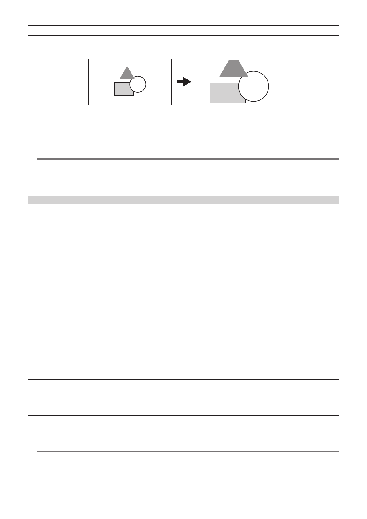
– 139 –
Chapter 5 Shooting — Convenient shooting functions
Setting the enlargement rate
1
Select the enlargement rate in the [VIDEO OUT/LCD/VF] menu → [FOCUS ASSIST] → [EXPAND VALUE].
f The enlargement rate can be selected from [×2], [×3], or [×4].
Setting the enlargement position
The enlargement position can be selected from nine positions when the enlarged display function is enabled.
In the case of the multidial: Turn the multidial to move the enlarged position. It will return to center when the multidial is pressed.
Operations can also be performed by pressing the <%> button, <(> button, <)> button, <=/&> button and <SET> button.
In case of touching the LCD monitor: The enlarged position will move by touching the vertical and horizontal arrow markers on the LCD monitor.
@
NOTE
t The enlarged display cannot be recorded.
t It will not perform enlarged display while displaying the color bars.
t Some of the displays such as marker will be hidden temporarily during enlarged display.
t The enlarged display and peaking display can be enabled at the same time by assigning each function to the <FOCUS ASSIST> button and USER
button.
Peaking display
The peaking display will outline the contour of the focused image in red, green, or white.
To enable the peaking display, press the <FOCUS ASSIST> button, press the USER button to which [PEAKING] is assigned, or touch the USER button
icon.
When enabling the peaking display by pressing the <FOCUS ASSIST> button
r Assigning [PEAKING] to the <FOCUS ASSIST> button
Set to enable/disable the peaking display by toggling the setting with the <FOCUS ASSIST> button.
1
Select the [VIDEO OUT/LCD/VF] menu → [FOCUS ASSIST] → [FOCUS ASSIST SW] → [PEAKING].
r Displaying the peaking display
1
Press the <FOCUS ASSIST> button.
Press the <FOCUS ASSIST> button again to return to the normal display.
When enabling the peaking display by pressing the USER button or touching the USER button icon
r Assigning [PEAKING] to the USER button
Enable/disable the peaking display with an arbitrary USER button.
1
Select the [CAMERA] menu → [USER SW] → [USER1] to [USER12] → [PEAKING].
r Displaying the peaking display
1
Press the USER button to which [PEAKING] is assigned or touch the USER button icon.
Press the USER button or touch the USER button icon again to return to the normal display.
Peaking display setting
1
Select the type of display in the [VIDEO OUT/LCD/VF] menu → [FOCUS ASSIST] → [FOCUS ASSIST SW].
[PEAKING]: Enables the peaking display.
[EXPAND]: Enables the enlarged display.
Setting the color for peaking display
Sets the color of the peaking display.
1
Select the color of the peaking display in the [VIDEO OUT/LCD/VF] menu → [FOCUS ASSIST] → [PEAKING COLOR].
f The color of the peaking display can be selected from [RED], [GREEN], or [WHITE].
@
NOTE
t The peaking display cannot be recorded.
t The peaking display is not displayed while displaying the color bars.
t The enlarged display and peaking display can be enabled at the same time by assigning each function to the <FOCUS ASSIST> button and USER
button.

– 140 –
Chapter 5 Shooting — Convenient shooting functions
Monochrome display
1
Select the [VIDEO OUT/LCD/VF] menu → [FOCUS ASSIST] → [BLACK & WHITE] → [ON].
@
NOTE
t The monochrome display can be enabled while the peaking display is functioning.
Select the [VIDEO OUT/LCD/VF] menu → [FOCUS ASSIST] → [BLACK & WHITE] → [DURING PEAKING].
Highlighting the outlines of images
It is easier to focus if the contours of images on the LCD monitor and viewnder are highlighted.
The intensity of contours on the LCD monitor does not affect the images output or recorded by the camera.
Set the intensity of contours in the [VIDEO OUT/LCD/VF] menu → [FOCUS ASSIST] → [DETAIL] → [ON] and adjust the [VIDEO OUT/LCD/VF] menu →
[FOCUS ASSIST] → [DETAIL LEVEL]/[DETAIL FREQ.].
Optical image stabilizer function
Camera shake can be reduced by using the optical image stabilizer function when shooting while holding the camera by hand.
You can use the hybrid optical image stabilizer function.
The hybrid optical image stabilizer function is an optical image stabilizer that combines optical and electronic methods.
Enabling/disabling the optical image stabilizer function
1
Select the [CAMERA] menu → [SW MODE] → [O.I.S.] → [ON].
f You can enable or disable the optical image stabilizer function by pressing the <O.I.S.> button.
Enabling/disabling the hybrid optical image stabilizer function
1
Select the [CAMERA] menu → [SW MODE] → [HYBRID O.I.S.] → [ON].
Enable the hybrid optical image stabilizer function for more powerful image stabilization when holding the camera and shooting a subject far away
with zoom.
When the hybrid optical image stabilizer function is enabled,
is displayed on the LCD monitor.
Optical image stabilizer settings according to shooting conditions
You can set the optical image stabilizer settings according to the shooting conditions.
1
Select the [CAMERA] menu → [SW MODE] → [O.I.S. MODE] → [NORMAL]/[PAN/TILT]/[STABLE].
[NORMAL]: Species the standard setting for a good balance of correction for large and small camera shake.
[PAN/TILT]: Species a setting appropriate for shooting that uses a lot of panning and tilting of the camera.
[STABLE]: Species a setting appropriate for xing a composition to shoot a subject.
@
NOTE
t Stabilization may not be possible when the camera has a large amount of shake.
t When using a tripod, disabling the optical image stabilizer function will allow you to obtain natural images.
Dynamic range stretcher function
By compressing the video signal levels of the high luminosity areas that are blown out in normal shooting while maintaining the contrast, the dynamic
range can be expanded.
The knee function, black gamma function, and the gamma mode function do not operate while the dynamic range stretcher function is enabled.
Enabling/disabling the dynamic range stretcher function
1
Select the [SCENE FILE] menu → [DRS] → [ON].
f The dynamic range stretcher function can be enabled or disabled by pressing the USER button to which [DRS] is assigned, or touching the USER
button icon.
Setting the dynamic range stretcher effect
1
Select the compression level with the [SCENE FILE] menu → [DRS EFFECT DEPTH].
Time stamp function
You can record the date and time of shooting on the images.
1
Select the information to record in the [RECORDING] menu → [TIME STAMP].
[OFF]: Does not superimpose the date and time.
[DATE]: Superimposes only the date.
[TIME]: Superimposes only the time.
[DATE&TIME]: Superimposes the date and time.
The date and time of recording is displayed in the bottom-center of the LCD monitor.

– 141 –
Chapter 5 Shooting — Convenient shooting functions
@
NOTE
t The order to display the year, month, and day of the time stamp follows the settings in the [OTHERS] menu → [CLOCK] → [DATE FORMAT].
t The display of the month for the time stamp to record on the image is in English.
t The size of the characters and the display position of the time stamp varies depending on the recording format.
t The time stamp is not recorded in the following cases.
‑ When the [SYSTEM] menu → [REC FORMAT] → [480-59.94i/AVCHD SA]/[576-50.00i/AVCHD SA] is set
‑ When the [SCENE FILE] menu → [VFR] → [ON] is set
‑ When the [SYSTEM] menu → [SUPER SLOW] → [ON] is set
‑ When the [NETWORK] menu → [NETWORK FUNC] → [STREAMING]/[NDI|HX] is set
t The position to display the time stamp can not be changed.
t The time stamp is displayed even in the screen of the LCD monitor, the image of the viewnder, and the image output from the <SDI
OUT>/<HDMI>/<AV OUT> terminals.
When set to the [SYSTEM] menu → [REC FORMAT] → [720-59.94p/AVCHD PM]/[720-50.00p/AVCHD PM], the time stamp displayed on the video in
the LCD monitor screen/viewnder will have different size of the characters and display position as the recorded time stamp.
t The external output is delayed by one frame when superimposing the time stamp.
t The [VIDEO OUT/LCD/VF] menu → [INDICATOR] → [DATE/TIME] setting is disabled when superimposing the time stamp.
t The time stamp is an image signal recorded superimposed to the subject. Therefore, the peaking display of the focus assist function and zebra pattern
detection are enabled also to the time stamp display. The time stamp is also displayed horizontally inverted when set to the [VIDEO OUT/LCD/VF]
menu → [LCD] → [SELF SHOOT] → [MIRROR].
Waveform monitor function
Waveform of the image can be displayed.
r Assigning [WFM] to the USER button
Set this function so that the waveform monitor can be displayed/hidden with an arbitrary USER button.
1
Select the [CAMERA] menu → [USER SW] → [USER1] to [USER12] → [WFM].
f [WFM] is assigned to the <USER 3> button in the factory settings.
r Displaying the waveform monitor
1
Press the USER button assigned to [WFM] or touch the USER button icon.
Press the USER button or touch the USER button icon again to return to the normal display.
f The display switches each time the USER button is pressed or the USER button icon is touched when the [VIDEO OUT/LCD/VF] menu → [EI
ASSIST] → [WFM MODE] → [WAVE/VECTOR] is set.
Setting the displaying of the waveform monitor
Displaying of the waveform and the vector can be switched.
1
Select the display of the waveform monitor in the [VIDEO OUT/LCD/VF] menu → [EI ASSIST] → [WFM MODE].
[WAVE]: Displays the waveform.
[VECTOR]: Displays the vector.
[WAVE/VECTOR]: Displays the waveform and the vector. The waveform, vector or no display toggles in order each time the USER button to which
[WFM] is assigned is pressed or the USER button icon is touched.
Setting the transmittance
The transmittance of the waveform monitor can be set.
1
Select the transmittance in the [VIDEO OUT/LCD/VF] menu → [EI ASSIST] → [WFM TRANSPARENCE].
f The transmittance can be selected from [0%], [25%], or [50%].
@
NOTE
t The waveform monitor cannot be recorded.
t The waveform monitor is not displayed when using enlarged display function in the focus assist function.
t The waveform monitor is automatically displayed when setting some of the menu to perform the image quality adjustment.
Digital zoom function
r Assigning [D.ZOOM] to the USER button
Set so enable/disable of the digital zoom function can be switched with an arbitrary USER button.
1
Select the [CAMERA] menu → [USER SW] → [USER1] to [USER12] → [D.ZOOM].

– 142 –
Chapter 5 Shooting — Convenient shooting functions
r Using the digital zoom function
1
Press the USER button to which [D.ZOOM] is assigned or touch the USER button icon.
The enlargement rate toggles from 2x, 5x, 10x and disabled in order each time the USER button is pressed or the USER button icon is touched.
@
NOTE
t The image quality decreases the higher the enlargement ratio when using the digital zoom.
t The digital zoom is cancelled when the power is turned off.
Level gauge
A level gauge that indicates the horizontal and vertical inclinations of the camera can be displayed on the LCD monitor.
The line of the level gauge is displayed in orange while the camera is inclined. The line of the level gauge will change from orange to light blue, and then
to white when the inclination of the camera is corrected. It will indicate up to approximately 30° in horizontal direction, and 30° in vertical direction.
1
Select the [VIDEO OUT/LCD/VF] menu → [LEVEL GAUGE] → [LEVEL GAUGE] → [ON].
@
NOTE
t The display of level gauge cannot be recorded.
t The level gauge is not displayed when the enlarged display function of the focus assist function is enabled, or when displaying the color bars.
t The level gauge may not display correctly while moving the camera.
t The level gauge may not display correctly when shooting with the camera inclined excessively upward or downward.
t Press the USER button to which [LEVEL GAUGE] is assigned or touch USER button icon to display or hide the level gauge.
t Press the USER button to which [LEVEL GAUGE SET] is assigned or touch the USER button icon to set the current horizontal and vertical directions
as the reference value of the level gauge. Restore the set value in the [VIDEO OUT/LCD/VF] menu → [LEVEL GAUGE] → [LEVEL GAUGE RESET].
Color bars
Color bars can be displayed. This is useful for image quality adjustment of a TV or an external monitor.
1
Press the <BARS> button.
Press the <BARS> button again to return to the normal display.
Setting the type of color bars
1
Select the type of color bars in the [OTHERS] menu → [COLOR BARS] → [COLOR BARS TYPE].
f The type of color bars can be selected from [SMPTE] or [FULL].
@
NOTE
t A smear may occur depending on the output resolution.
Setting the audio test signal output
Sets if the audio test signal (tone signal of rating level 1 kHz) can be output or not when the color bars are displayed.
1
Select the [OTHERS] menu → [COLOR BARS] → [TEST TONE] → [ON].
– 143 –
Chapter 5 Shooting — Operation icon screen display
Operation icon screen display
You can select the scene le or execute the functions assigned to [USER8] through [USER12].
Displaying the operation icon screen
1
Press the multidial or the <SET> button while [ ICONS] is displayed in the LCD monitor, or touch the LCD monitor for one
second or longer while the camera image screen is displayed.
f The operation icon screen is displayed.
The camera returns to the camera image screen from the operation icon screen in the following cases.
‑ When the <EXIT> button is pressed
‑ When anything other than the icon is touched
‑ When the touch operation of the LCD monitor and button operation of the <%> button, <(> button, <)> button, <=/&> button, or <SET>
button are not performed for approximately ve seconds
F1:
************************************************
F2: F3: F4: F5: F6:
1
2
USER8
USER9
USER10
USER11
USER12
1 Scene le (1 to 6) icon
Align the cursor and press the multidial or the <SET> button, or touch the icon to select each scene le.
The name of each scene le is displayed on the second line of the icon.
2 [USER8] to [USER12] icon
Align the cursor and press the multidial or the <SET> button, or touch the icon to execute the function assigned to [USER8] through [USER12].
Each function assigned to [USER8] through [USER12] is displayed in the icon.
– 144 –
Chapter 5 Shooting — Multi manual function
Multi manual function
Operate the multidial to change settings and perform other operations without displaying the menu.
Operations can also be performed by pressing the <=/&> button, <(> button, <SET> button, and <EXIT> button.
You can execute the following functions.
Display of the camera image screen Function
[
ICONS]
Displays the operation icon screen.
[
WB]
Sets the variable value for the white balance.
[
SHUTTER]
Sets the shutter speed.
[
SYNCHRO]
Sets the synchro scan shutter speed.
[
FRAME RATE]
Sets the frame rate of the variable frame rate recording function.
[
AREA]
Adjusts the area size/area position of the area mode function.
[
AF AREA]
Adjusts the width of the auto focus area.
Displaying the operation icon screen
1
Turn the multidial to display the [ ICONS].
2
Press the multidial.
The operation icon screen is displayed.
Setting the variable value for the white balance
1
Turn the multidial to display the [ WB].
2
Press the multidial.
The white balance display is highlighted in orange.
3
Turn the multidial to select the color temperature.
4
Press the multidial.
The setting changes to the value displayed and exits.
Press the <EXIT> button to exit without changing the setting.
@
NOTE
t [
WB] is only displayed when the following conditions are satised.
‑ The <WHITE BAL> switch is in the <PRST> position
‑ The [CAMERA] menu → [SW MODE] → [W.BAL PRESET] is set to [VAR]
‑ The auto tracking white balance function is disabled
‑ IR recording is disabled
Setting the shutter speed
1
Turn the multidial to display the [ SHUTTER].
2
Press the multidial.
The shutter speed display is highlighted in orange.
3
Turn the multidial to select the shutter speed.
4
Press the multidial.
The setting changes to the value displayed and exits.
The synchro scan settings start when the shutter speed display is a decimal.
Press the <EXIT> button to exit without changing the setting.
@
NOTE
t [
SHUTTER] is displayed when the shutter function is enabled and set to manual shutter.
t Press the <SHUTTER> button to enable/disable the shutter function.
Setting the synchro scan shutter speed
1
Turn the multidial to display the [ SHUTTER].
2
Press the multidial.
The shutter speed display is highlighted in orange.
3
Turn the multidial to select the shutter speed of the decimal display.

– 145 –
Chapter 5 Shooting — Multi manual function
4
Press the multidial.
[
SYNCHRO] is displayed.
5
Turn the multidial to select the synchro scan shutter speed.
6
Press the multidial.
The setting changes to the value displayed and ends.
Press the <EXIT> button to exit without changing the setting.
Setting the frame rate of the variable frame rate recording function
1
Turn the multidial to display the [ FRAME RATE].
2
Press the multidial.
The frame rate display is highlighted in orange.
3
Turn the multidial to select the frame rate.
4
Press the multidial.
The setting changes to the value displayed and exits.
Press the <EXIT> button to exit without changing the setting.
When the REC button is pressed while it is possible to record, exits from the setting after changing the setting to the displayed value, and then the
recording is started.
@
NOTE
t [
FRAME RATE] is displayed when the [SCENE FILE] menu → [VFR] → [ON] and the [SYSTEM] menu → [SUPER SLOW] → [OFF] are set.
Adjusting the area size/area position of the area mode function
1
Turn the multidial to display the [ AREA].
2
Press the multidial.
3
Turn the multidial to change the size of the area frame.
4
Press the <%> button, <(> button, <)> button, or <=/&> button to change the position of the area frame.
5
Press the multidial.
The setting is changed to the displayed size/position and exits.
The setting is changed and exits also by pressing the <EXIT> button.
@
NOTE
t [
AREA] is displayed when the area mode function is enabled.
Adjusting the width of the auto focus area
Adjusts the width of the area that auto focus is enabled according to the size of the subject.
1
Press the USER button assigned to [AF AREA] or touch the USER button icon while the camera image screen is displayed.
[
AF AREA] is displayed in the camera image screen.
2
Turn the multidial to adjust the auto focus area frame.
3
Press the multidial.
The setting changes to the width displayed and exits.
Press the <EXIT> button to exit without changing the setting.
To release the setting, press the USER button to which [AF AREA] is assigned or touch the USER button icon.
To adjust the setting again, press the multidial when [
AF AREA] is displayed in yellow and perform Steps 2 to 3.
@
NOTE
t The width of the auto focus area frame can be adjusted even if the [CAMERA] menu → [SW MODE] → [AF AREA WIDTH] → [ON] is set and the
menu is closed.

Data including additional information such as image, audio, and meta data that are recorded by single shooting is saved as a clip. Playback, copy, etc.,
of the clip can be performed on the camera.
Chapter 6 Playback
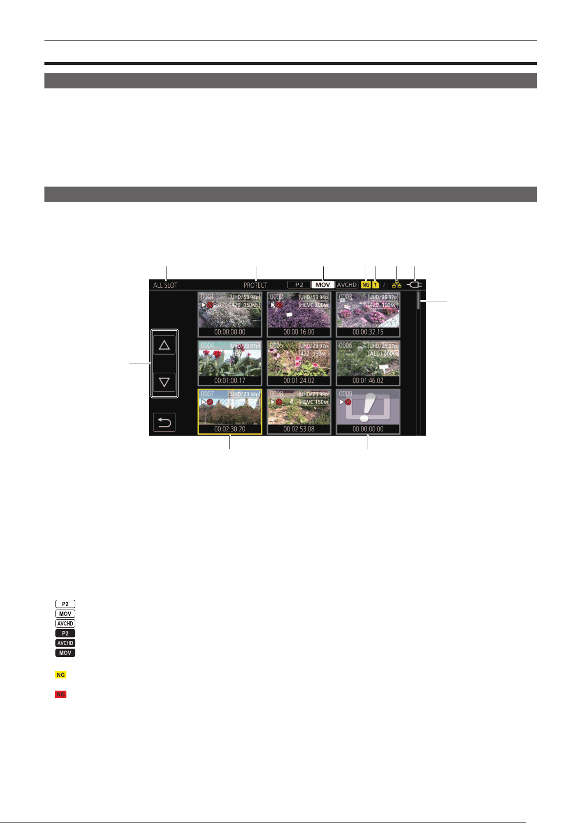
– 147 –
Chapter 6 Playback — Thumbnail operation
Thumbnail operation
Thumbnail operation overview
A clip is a group of data recorded by a single shooting, which includes additional information such as image, audio, and meta data.
The following operations can be performed while viewing the clip thumbnails displayed on the LCD monitor.
f Playback
f Delete
f Protect (only the clips recorded in MOV/AVCHD)
f Copy (only the clips recorded in P2/AVCHD)
f The two methods of operation are the method to operate with the multidial or the <%> button, <(> button, <)> button and <=/&> button, or a
method to operate by touching the LCD monitor.
Thumbnail screen
Press the <THUMBNAIL> button to display the thumbnail screen while displaying the camera image screen.
Press the <THUMBNAIL> button again to display the camera image screen.
The clips in the recording le format (P2/MOV/AVCHD) selected in the [SYSTEM] menu → [FILE FORMAT] are displayed in the thumbnail screen.
Also, menu in the thumbnail screen can be operated by pressing the <MENU> button while the thumbnail screen is displayed.
1
11
2 3 4 5 6 7
10
8 9
1 Clip status display
[ALL SLOT]: Displays all the clips recorded on every memory card in each card slot. Displays in [ALL SLOT] when the thumbnail screen is displayed
from the camera image screen.
[SLOT1]: Displays only the clips recorded on the memory card in card slot 1.
[SLOT2]: Displays only the clips recorded on the memory card in card slot 2.
[SLOT1→SLOT2]: Displayed when copying from the memory card in card slot 1 to the memory card in card slot 2.
[SLOT2→SLOT1]: Displayed when copying from the memory card in card slot 2 to the memory card in card slot 1.
[SAME FORMAT]: Displays only the clips recorded in the same format as the system format.
Clips recorded in the same format match the current settings for each item of the [SYSTEM] menu → [FREQUENCY]/[FILE FORMAT]/[REC
FORMAT].
2 Function display
This is displayed during the operation of copy, delete, protect, etc.
3 Recording mode
: Displayed when P2 is selected as the recording le format.
: Displayed when MOV is selected as the recording le format.
: Displayed when AVCHD is selected as the recording le format.
: Displayed when MOV or AVCHD is selected as the recording le format and there is at least one P2 clip on any of the memory cards.
: Displayed when P2 or MOV is selected as the recording le format and there is at least one AVCHD clip on any of the memory cards.
: Displayed when P2 or AVCHD is selected as the recording le format and there is at least one MOV clip on any of the memory cards.
4 Defective clip status
: Displayed when P2 is selected as the recording le format and there is at least one defective P2 clip that may be repaired in the thumbnail
screen.
: Displayed when P2 is selected as the recording le format and there is at least one defective P2 clip that cannot be repaired in the thumbnail
screen.
(No display): There is no defective P2 clip in the thumbnail screen.
5 Media status display
The card slot number of the memory card where the clip in the cursor position is recorded is displayed in yellow.
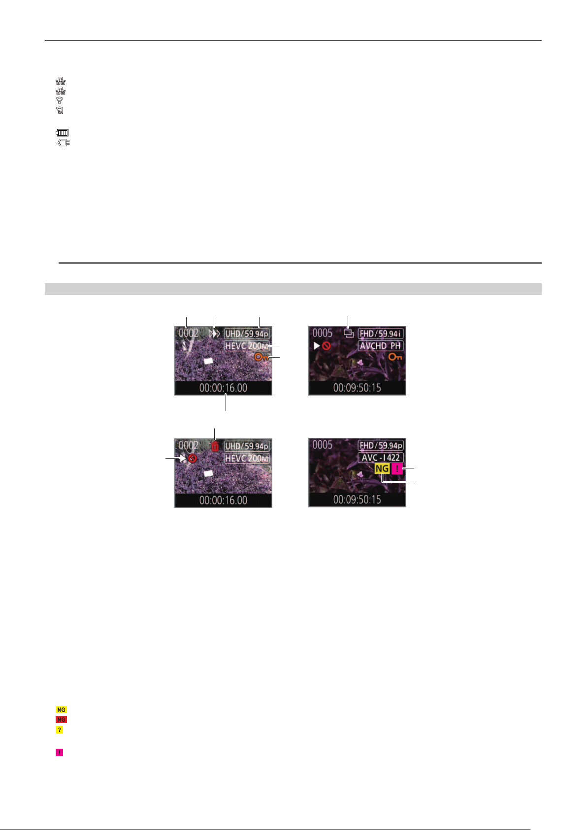
– 148 –
Chapter 6 Playback — Thumbnail operation
6 Displaying the connection status of the wired LAN/wireless LAN
Displays the connection status of the wired LAN and wireless LAN.
(No display): It is not connected to the wired LAN or wireless LAN. It is set to the [NETWORK] menu → [DEVICE SEL] → [OFF].
: A status where the wired LAN is set and ROP is not connected.
: A status where the wired LAN is set and ROP is connected.
: A status where the wireless LAN is set and ROP is not connected.
: A status where the wireless LAN is set and ROP is connected.
7 Power status display
: Displays the remaining battery level while powered with the battery.
: Displayed when powered with the AC adaptor.
8 Cursor
9 Clip that cannot be played back
Displays when the clip cannot be played back in the camera such as standard violation.
10 Page switching button
Switches the page of the thumbnail screen.
[`]: Moves to previous page
[{]: Moves to next page
11 Scroll bar
Indicates which part of the whole thumbnail is currently being viewed.
@
NOTE
t When P2 is selected as the recording le format, a clip recorded over multiple memory cards is displayed as one clip.
Display of the clips in the thumbnail screen
2
7
1
8
9
3
4
6
5
11
10
1 Thumbnail number
Displays the thumbnail number in [0001] to [9999].
Normally, the number assigned to the clip in the order of recording is displayed.
2 Resume play status
3 Number of recording pixels, system frequency
4 Recording le format, recording codec
5 Protection status of the clip
This is displayed when the clip is protected.
6 Standard time code/clip name
The rst eight digits for the time code when starting shooting of a clip or the le name of the clip are displayed in alphanumeric.
The information to display is set in the [THUMBNAIL] menu → [DISPLAY] → [DATA].
7 Delete selection status
8 Clip that cannot be played back
This is displayed when the clip cannot be played back with the camera because the system frequency is different, etc.
9 Copy selection status
This is displayed when the clip is selected.
10 Defective clip/unknown clip
: This is displayed for a defective P2 clip that may be repaired.
: This is displayed for a defective P2 clip that cannot be repaired.
: This is displayed for a P2 clip with a different format for P2 standard.
11 Incomplete clip
: This is displayed for a P2 clip when the clip is recorded over multiple memory cards, and any of those memory cards are not inserted.
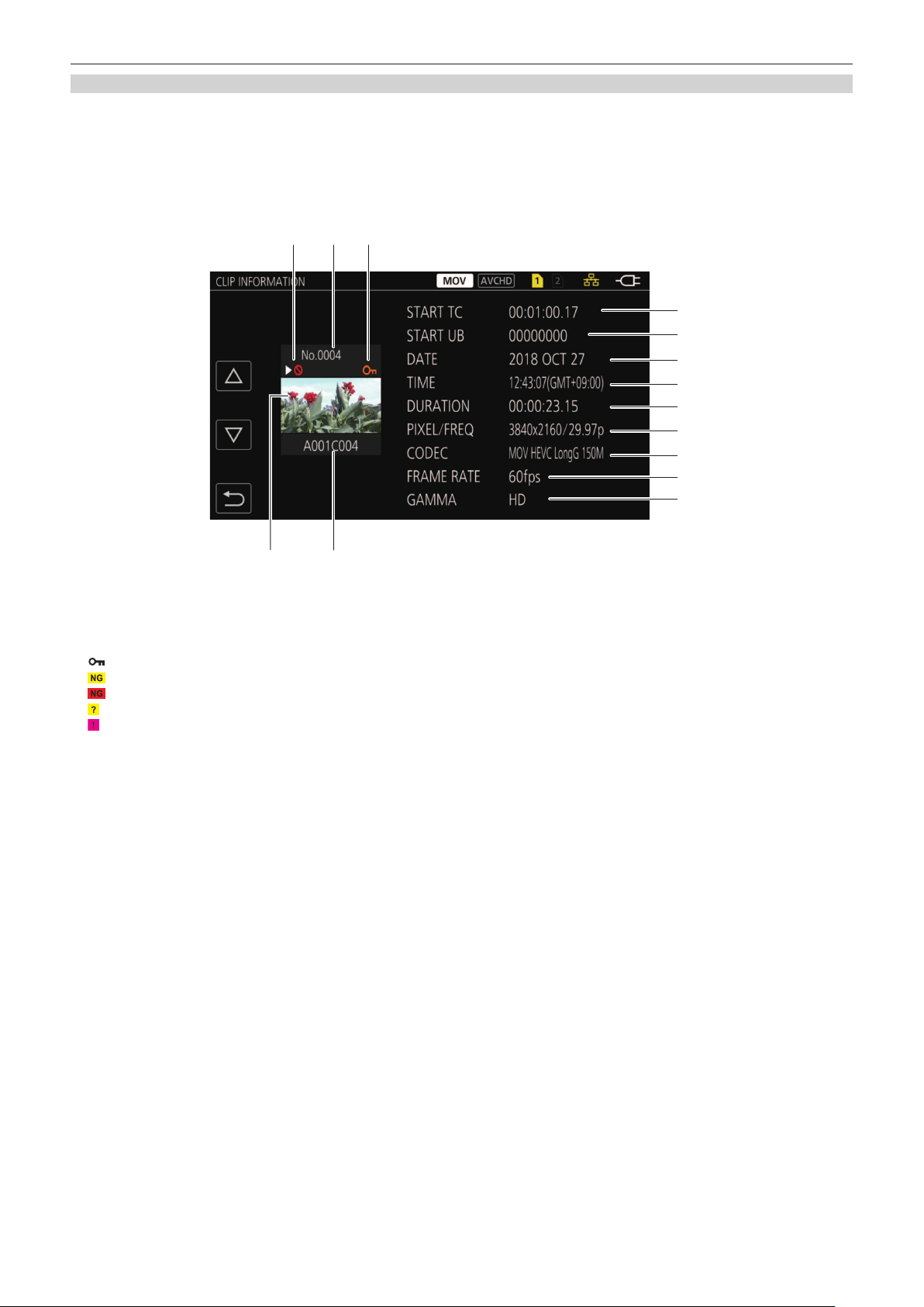
– 149 –
Chapter 6 Playback — Thumbnail operation
Display of clip information
Displays the information of the clip where the cursor is positioned.
1
Move the yellow cursor to the clip to display the clip information.
2
Select the [THUMBNAIL] menu → [CLIP] → [INFORMATION].
The clip information is displayed.
r Clip information
1 2 3
6
4 5
7
8
9
10
11
12
13
14
1 Clip that cannot be played back
This is displayed when the clip cannot be played back with the camera because the system frequency is different, etc.
2 Thumbnail number
3 Protect status of the clip/defective clip/unknown clip/incomplete clip
: This is displayed when the clip is protected.
: This is displayed for a defective P2 clip that may be repaired.
: This is displayed for a defective P2 clip that cannot be repaired.
: This is displayed for a P2 clip with a different format for P2 standard.
: This is displayed for a P2 clip when the clip is recorded over multiple memory cards, and any of those memory cards are not inserted.
4 Thumbnail image
5 Clip name
6 [START TC]
Displays the time code value at the start of the recording.
7 [START UB]
Displays the user bits value at the start of the recording.
8 [DATE]
Displays the date of the recording.
9 [TIME]
Displays the time at the start of recording.
10 [DURATION]
Displays the time length of the clip.
11 [PIXEL/FREQ]
Displays the recording format of the clip.
12 [CODEC]
Displays the recording le format and the recording codec of the clip.
13 [FRAME RATE]
Displays the recording frame rate of the clip.
Displays when the variable frame rate recording function is enabled and the clip is recorded in a frame rate different from the system frequency.
14 [GAMMA]
Displays the gamma of the clip.
Displays when the [SYSTEM] menu → [FILE FORMAT] → [P2]/[MOV] is set and recording is performed..
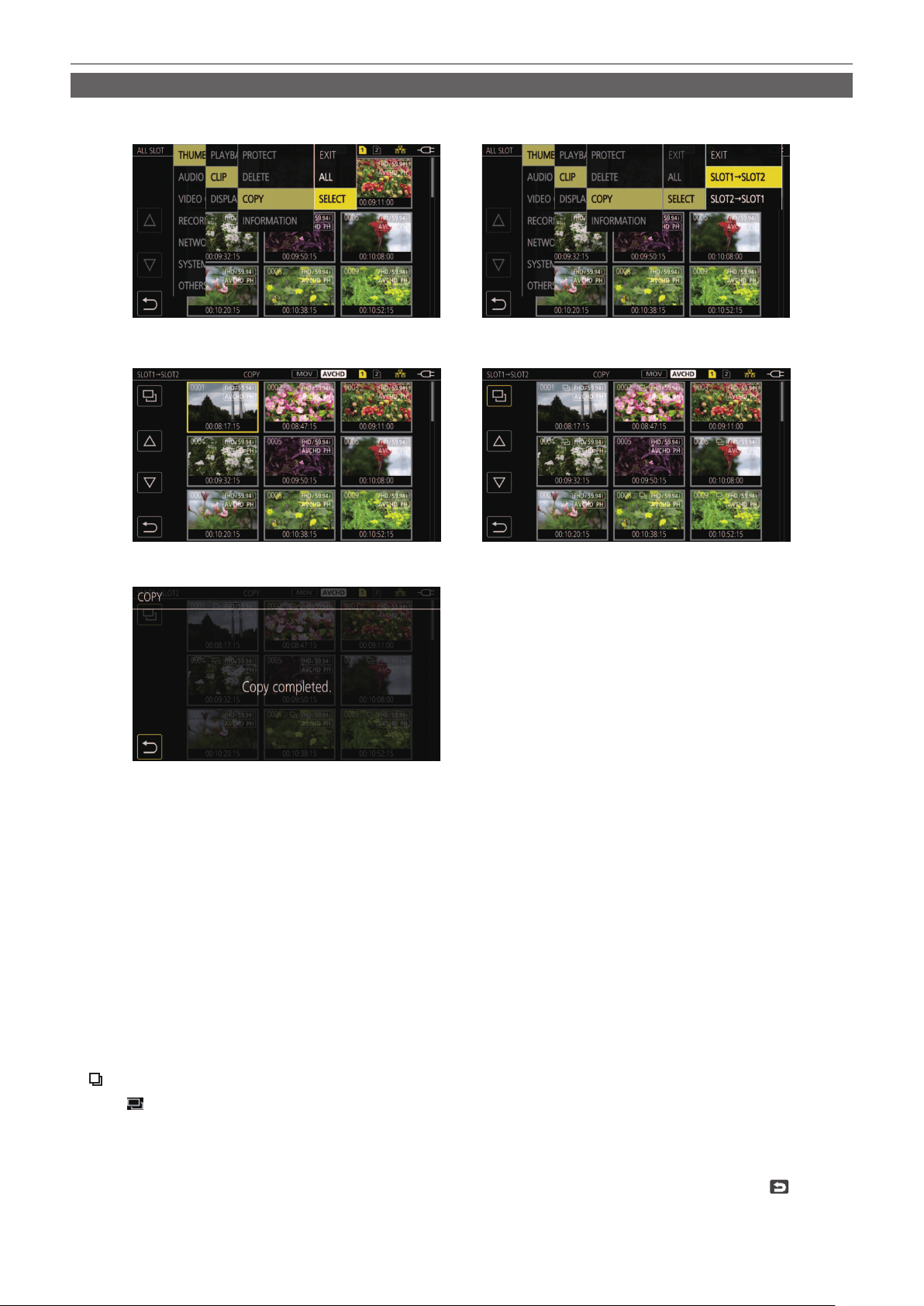
– 150 –
Chapter 6 Playback — Thumbnail operation
Copying clips
Clips can be copied between memory cards.
Only the clip recorded in P2 or AVCHD can be copied.
Fig. 1 Fig. 2
Fig. 4Fig. 3
Fig. 5
1
Press the <THUMBNAIL> button.
The thumbnail screen is displayed.
2
Press the <MENU> button while the thumbnail screen is displayed.
The menu is displayed.
3
Select the [THUMBNAIL] menu → [CLIP] → [COPY].
4
Select [SELECT]. (Fig. 1)
f Selecting [ALL] copies all the clips between the memory cards.
5
Select the card slot for the copy destination. (Fig. 2)
The clips on the memory card of the copy source is displayed in the thumbnail screen. (Fig. 3)
f [SLOT1→SLOT2]: Copies clips from the memory card in card slot 1 to the memory card in card slot 2.
f [SLOT2→SLOT1]: Copies clips from the memory card in card slot 2 to the memory card in card slot 1.
6
Select the clip to copy in the thumbnail screen.
is displayed on the selected clip.
7
Select
. (Fig. 4)
f This can also be selected by pressing and holding the multidial.
8
When the confirmation message is displayed, select [SET].
Progress bar is displayed, and the copy of the clip starts.
[OVERWRITE?] is displayed when there is a same P2 clip in the copy destination. Select [SET] when overwriting the clip, and select
when not
overwriting the clip.
f To cancel the copy midway, select [CANCEL].
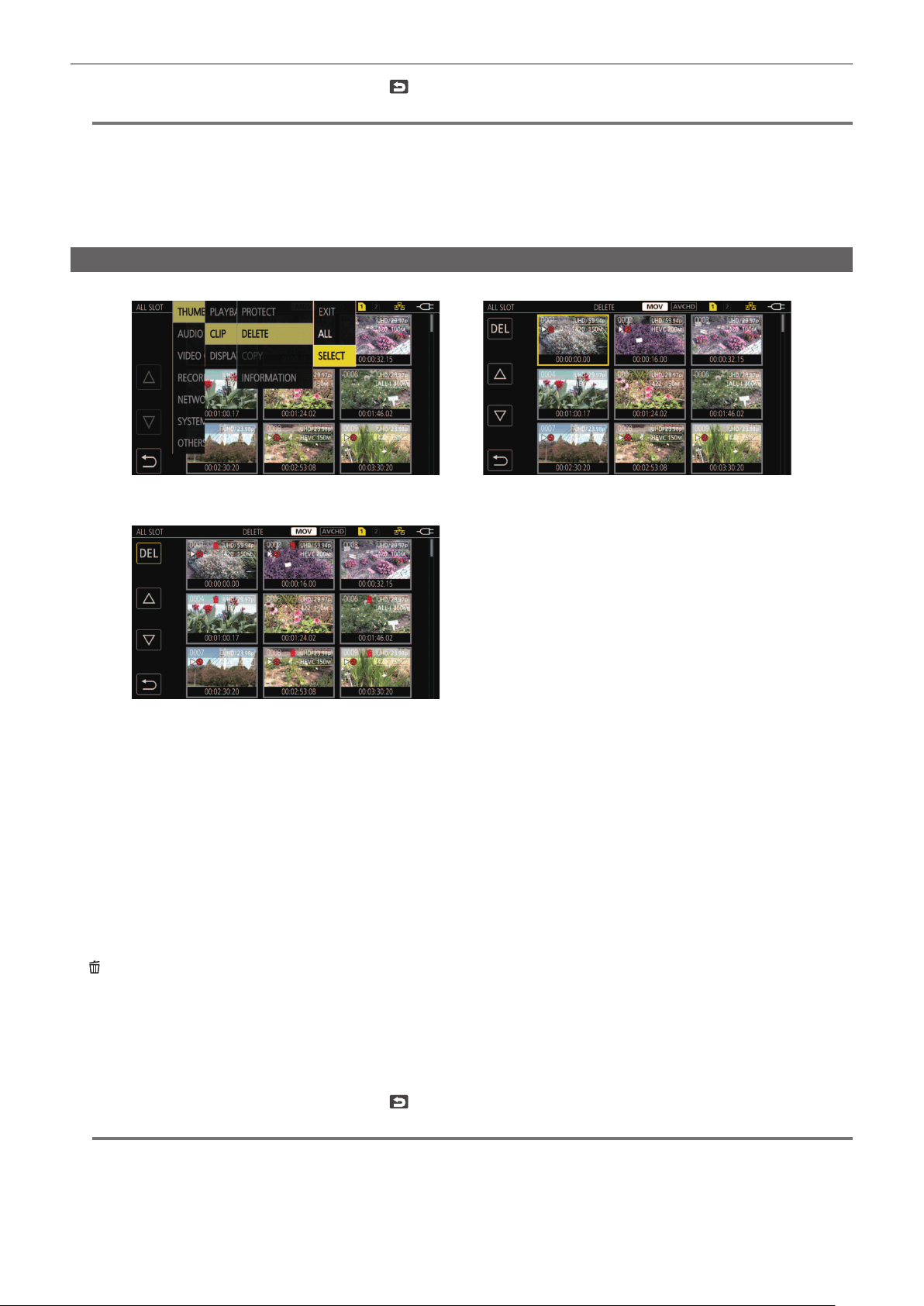
– 151 –
Chapter 6 Playback — Thumbnail operation
9
When the completion message is displayed, select . (Fig. 5)
@
NOTE
t The clip whose recording le format is MOV cannot be copied.
t The copy is not possible when the volume of the selected clip is larger than the available card capacity of the destination.
t It cannot copy when the copy destination card is write protected.
t The copy is not possible when the maximum number of the clips will exceed.
t The copy is not possible when the maximum number of the playlist will exceed.
t The P2 clip exceeding 4 GB cannot be copied to a memory card of 32 GB or less.
t The P2 clip recorded over multiple memory cards cannot be copied to a same memory card.
Deleting clips
Deletes the clip.
Fig. 1 Fig. 2
Fig. 3
1
Press the <THUMBNAIL> button.
The thumbnail screen is displayed.
2
Press the <MENU> button while the thumbnail screen is displayed.
The menu is displayed.
3
Select the [THUMBNAIL] menu → [CLIP] → [DELETE].
4
Select [SELECT]. (Fig. 1)
The thumbnail screen is displayed. (Fig. 2)
f When [ALL] is selected, all the clips displayed in the thumbnail screen are deleted.
The clip that is not displayed in the thumbnail screen is not deleted.
5
Select the clip to delete in the thumbnail screen.
is displayed on the selected clip.
6
Select [DEL]. (Fig. 3)
f This can also be selected by pressing and holding the multidial.
7
When the confirmation message is displayed, select [SET].
Progress bar is displayed, and the deleting of the clip starts.
f To cancel midway, select [CANCEL].
8
When the completion message is displayed, select
.
@
NOTE
t The protected clip cannot be deleted.
t It cannot delete when the card with the clip to delete is write protected.
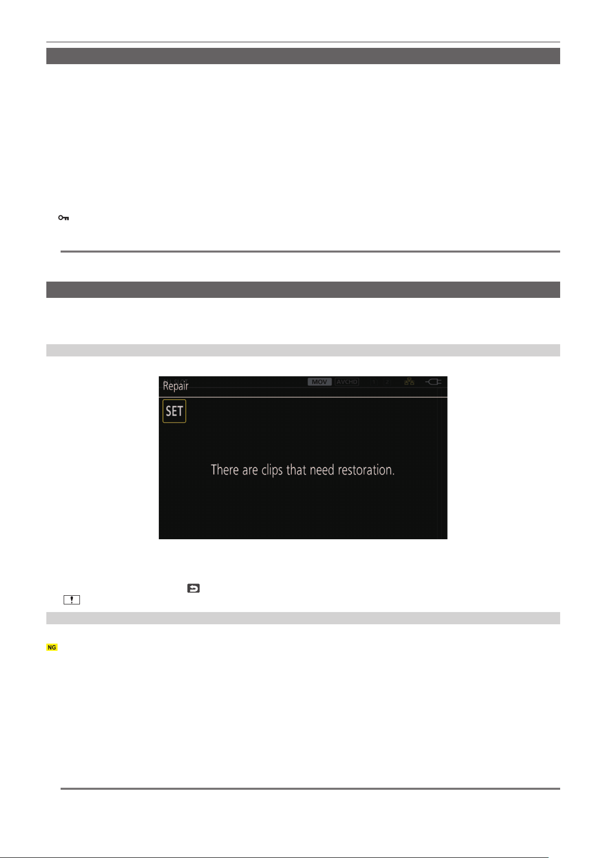
– 152 –
Chapter 6 Playback — Thumbnail operation
Protecting clips
The clip recorded in MOV or AVCHD can be protected.
1
Press the <THUMBNAIL> button.
The thumbnail screen is displayed.
2
Press the <MENU> button while the thumbnail screen is displayed.
The menu is displayed.
3
Select the [THUMBNAIL] menu → [CLIP] → [PROTECT].
4
Select [SELECT].
The thumbnail screen is displayed.
5
Select the clip to protect in the thumbnail screen.
is displayed on the selected clip.
f Protect is canceled when the protected clip is selected.
@
NOTE
t It cannot protect when the card with the clip to protect is write protected.
t The clip whose recording le format is P2 cannot be protected.
Restoring clips
In following cases, restoration of the clip may be required depending on the condition. It may take some time to restore depending on the error.
f When the memory card in the card slot that is ashing is removed while the card 1 access lamp or the card 2 access lamp is ashing
f When the power is turned off by removing the battery or the AC adaptor while recording or performing record completion process
Restoring a clip (MOV format/AVCHD format)
An error as in following gure is displayed when MOV or AVCHD is selected as the recording le format.
COPY
Fig. 1
1
Select [SET] in the error message screen. (Fig. 1)
f Once the repair is completed, select
in the conrmation message. It will return to the previous screen.
f
is displayed on the clip when an abnormal management information is detected while displaying the thumbnail.
Restoring a clip (P2 format)
An error message is not displayed when P2 is selected as the recording le format.
is displayed in the thumbnail screen when there is at least one defective P2 clip that may be repaired in the thumbnail screen. In such case, the clip
can be repaired in following procedure.
1
Press the <THUMBNAIL> button.
The thumbnail screen is displayed.
2
Press the <MENU> button while the thumbnail screen is displayed.
The menu is displayed.
3
Select the [THUMBNAIL] menu → [CLIP] → [REPAIR].
4
Select [YES].
All the defective P2 clips that may be repaired in the thumbnail screen are repaired.
@
NOTE
t Do not remove the memory card in the card slot that is ashing, or do not remove the battery or the AC adaptor when the card 1 access lamp/card 2
access lamp is ashing in orange. Doing so will cause damage to the memory card.
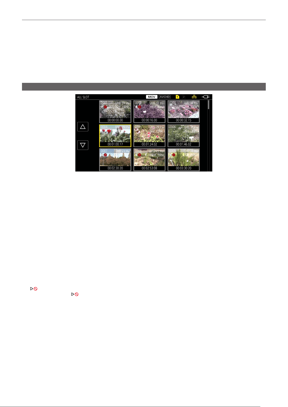
– 153 –
Chapter 6 Playback — Thumbnail operation
t Use a sufciently charged battery or AC adaptor.
t It may not be possible to completely repair depending on the condition of the data.
t To restore the clips, it is necessary that the clips are recorded for more than a certain amount of time. Especially in the following cases, the clips may
not be restored, because the number of frames to be recorded is small.
‑ When the variable frame rate recording function is enabled, and the frame rate lower than the system frequency is set.
‑ When the interval recording function is enabled.
t The clips shot before the power was turned off will not be able playback if the repair fails.
Also, it may not be possible to record any more.
t If data recorded with other device is repaired, it may not be able to play back on the camera or other device.
t If the repair failed, turn off the camera, and turn it back on after waiting for a while. If the repair fails repeatedly, format with the camera. All data will be
erased when it is formatted, and it cannot be restored.
t Display of the thumbnail become slower when the thumbnail information is repaired.
Playing back clips
1
In the [SYSTEM] menu → [FREQUENCY], select the system frequency to play back.
2
In the [SYSTEM] menu → [FILE FORMAT], select the file format to play back.
3
In the [SYSTEM] menu → [REC FORMAT], select the signal format and codec mode to play back.
4
Press the <THUMBNAIL> button.
The thumbnail screen is displayed.
5
Press the <MENU> button while the thumbnail screen is displayed.
The menu is displayed.
6
In the [THUMBNAIL] menu → [PLAYBACK] → [CLIP SEL], select the card slot of the memory card to play back.
[ALL SLOT]: Displays all the clips recorded on every memory card in each card slot.
Displays in the order of the clips in card slot 1, and then clips in the card slot 2 when MOV or AVCHD is selected as the recording le format.
Displays the clips in all the card slots in the order of the recording date and time when P2 is selected as the recording le format.
[SLOT1]: Displays only the clips recorded on the memory card in card slot 1.
[SLOT2]: Displays only the clips recorded on the memory card in card slot 2.
[SAME FORMAT]: Displays only the clips recorded in the same format as the system format.
Clips recorded in the same format match the current settings for each item of the [SYSTEM] menu → [FREQUENCY]/[FILE FORMAT]/[REC
FORMAT].
7
Select the clip to play back.
f
is displayed on the clip that cannot be played back.
f To play back the clip with
displayed, check the information of the clip with the clip information, and try operating from the beginning again.

– 154 –
Chapter 6 Playback — Thumbnail operation
Playback from button operations and operation icons
TCR 12:59:59:23
CH1
CH2
Direct playback bar
Playback operation Operating procedure
Playback/pause
Touch
/ or press the <=/&> button.
Fast-reverse playback
Touch
or press the <%> button. Touch twice to increase the speed.
Fast-forward playback
Touch
or press the <)> button. Touch twice to increase the speed.
Stop (return to thumbnail screen)
Touch
or press the <(> button.
Skip playback
(cue up of the clip)
Touch the LCD monitor while playing back, and slide from right to left (left to right).
When sliding from left to right, the clip skips to the beginning of the previous clip if the current playback
position of the clip is at less than three seconds from the beginning. The clip skips to the beginning of the
current clip if the current playback position of the clip is at three seconds or more from the beginning.
Skip playback is also possible by pressing the <)> button or <%> button while paused.
Slow playback
Touch and hold
or press and hold <+> of the <AUDIO MON/ADV> button while paused.
(
or <−> of the <AUDIO MON/ADV> button for reverse slow playback)
Touch
or press and hold the <+> of the <AUDIO MON/ADV> button for continuous frame-by-frame
playback.
f Touch
/ or press the <=/&> button to return to normal playback.
f The frame-by-frame interval and the display time for each frame for the reverse slow playback differ
depending on the type of the clip.
Frame-by-frame playback
Touch
or press <+> of the <AUDIO MON/ADV> button while paused.
(
or <−> of the <AUDIO MON/ADV> button for reverse frame-by-frame playback)
f Touch
/ or press the <=/&> button to return to normal playback.
f The frame-by-frame interval for reverse frame-by-frame playback differs depending on the type of the
clip.
Direct playback Touch the direct playback bar, or slide it while touching.
f The playback video is paused during the operation. Playback is started by releasing the nger.
@
NOTE
t Operations of the camera or some performance may become slow for the clip with large le size.
t Operations of the camera or some performance may become slow when there are large number of clips on the memory card.
t Playback will stop once by switching the card slot when MOV or AVCHD is selected as the recording le format, and the [THUMBNAIL] menu →
[PLAYBACK] → [CLIP SEL] → [ALL SLOT]/[SAME FORMAT] is set, and then the clips of all the memory cards are displayed. Playback is not possible
across two memory cards.
t Playback stops when the memory card is removed during playback.

– 155 –
Chapter 6 Playback — Useful playback function
Useful playback function
Resume play
When the playback of a clip is stopped midway, it will start the playback from the position that stopped the playback when it is played back the next time.
1
Select the [THUMBNAIL] menu → [PLAYBACK] → [RESUME PLAY] → [ON].
When the playback of a clip is stopped midway, [L] is displayed on the clip in the thumbnail screen.
@
NOTE
t Resume playback is canceled in following cases.
‑ When the power is turned off
‑ When the thumbnail screen is canceled by pressing the <THUMBNAIL> button
‑ When the [SYSTEM] menu → [REC FORMAT] is changed

– 156 –
Chapter 6 Playback — Still image recording function
Still image recording function
One frame of the recorded video can be recorded as a still image.
Number of pixels of the still image to be recorded is same as the number of pixels of the recorded video.
1
Select by touching
or pressing the multidial at the scene to be recorded as a still image while playing back.
The still image is recorded in the memory card being played back.
@
NOTE
t The playback will pause when a still image is recorded.
t Recorded still image cannot be displayed in thumbnail, played back, copied, or deleted in the camera.
t [INVALID] is displayed when the still image cannot be recorded in cases such as there is not enough remaining recording capacity in the memory card.
t Still image cannot be recorded for the clip recorded by setting the [SYSTEM] menu → [REC FORMAT] to [480-59.94i/AVCHD SA] or [576-50.00i/
AVCHD SA].

This chapter describes the screen displayed on the output video and LCD monitor.
Chapter 7 Output and Screen Display
– 158 –
Chapter 7 Output and Screen Display — Output format
Output format
The format to be output differs depending on the setting in the [SYSTEM] menu → [FREQUENCY]/[REC FORMAT].
Format that can be output from the <SDI OUT> terminal
The format that can be output from the <SDI OUT> terminal differs with following combination of the settings.
f [SYSTEM] menu → [FREQUENCY]
f [SYSTEM] menu → [REC FORMAT]
f [VIDEO OUT/LCD/VF] menu → [SDI OUT] → [OUT FORMAT]
Item
Output Format
[OUT FORMAT]
[FREQUENCY]
[REC FORMAT]
Resolution Frequency
[59.94Hz]
3840×2160
59.94p
1920×1080 59.94p
1920×1080 59.94i (Factory setting)
29.97p
1920×1080 29.97PsF
23.98p
1920×1080 23.98PsF
1920×1080
59.94p
1920×1080 59.94p
1920×1080 59.94i (Factory setting)
720×480 59.94i
59.94i
1920×1080 59.94i (Factory setting)
720×480 59.94i
29.97p
1920×1080 29.97p (Factory setting)
720×480 59.94i
23.98p
1920×1080 23.98p (Factory setting)
720×480 59.94i
1280×720
59.94p
1280×720 59.94p (Factory setting)
720×480 59.94i
720×480
59.94i
720×480 59.94i
[50.00Hz]
3840×2160
50.00p
1920×1080 50.00p
1920×1080 50.00i (Factory setting)
25.00p
1920×1080 25.00PsF
1920×1080
50.00p
1920×1080 50.00p
1920×1080 50.00i (Factory setting)
720×576 50.00i
50.00i
1920×1080 50.00i (Factory setting)
720×576 50.00i
25.00p
1920×1080 25.00PsF (Factory setting)
720×576 50.00i
1280×720
50.00p
1280×720 50.00p (Factory setting)
720×576 50.00i
720×576
50.00i
720×576 50.00i
@
NOTE
t The 3840×2160 output is not supported.
t [OUT FORMAT] restores the factory settings when the settings of [FREQUENCY] and [REC FORMAT] change and the current setting values of [OUT
FORMAT] cannot be acquired.
t The output format when playing back from the thumbnail screen is as follows.
‑ It will be the value set in [OUT FORMAT] when the recording resolution of the playback clip is the same as [REC FORMAT].
‑ It will be factory setting of [OUT FORMAT] when the recording resolution of the playback clip is different from [REC FORMAT].
Format that can be output from the <HDMI> terminal
The format that can be output from the <HDMI> terminal differs with following combination of the settings.
f [SYSTEM] menu → [FREQUENCY]
f [SYSTEM] menu → [REC FORMAT]
f [VIDEO OUT/LCD/VF] menu → [HDMI OUT] → [OUT FORMAT]
Item
Output format
[OUT FORMAT]
[FREQUENCY]
[REC FORMAT]
Resolution Frequency
[59.94Hz]
3840×2160
59.94p
3840×2160 59.94p
3840×2160 59.94p (4:2:0/8-bit)
1920×1080 59.94p (Factory setting)
1920×1080 59.94i
29.97p
3840×2160 29.97p
1920×1080 29.97p (Factory setting)
23.98p
3840×2160 23.98p
1920×1080 23.98p (Factory setting)
1920×1080
59.94p
1920×1080 59.94p (Factory setting)
1920×1080 59.94i

– 159 –
Chapter 7 Output and Screen Display — Output format
Item
Output format
[OUT FORMAT]
[FREQUENCY]
[REC FORMAT]
Resolution Frequency
59.94i
1920×1080 59.94i
29.97p
1920×1080 29.97p
23.98p
1920×1080 23.98p
1280×720
59.94p
1280×720 59.94p
720×480
59.94i
720×480 59.94p
[50.00Hz]
3840×2160
50.00p
3840×2160 50.00p
3840×2160 50.00p (4:2:0/8-bit)
1920×1080 50.00p (Factory setting)
1920×1080 50.00i
25.00p
3840×2160 25.00p
1920×1080 25.00p (Factory setting)
1920×1080
50.00p
1920×1080 50.00p (Factory setting)
1920×1080 50.00i
50.00i
1920×1080 50.00i
25.00p
1920×1080 25.00p
1280×720
50.00p
1280×720 50.00p
720×576
50.00i
720×576 50.00p
@
NOTE
t [OUT FORMAT] restores the factory settings when the settings of [FREQUENCY] and [REC FORMAT] change and the current setting values of [OUT
FORMAT] cannot be acquired.
t The output format when playing back from the thumbnail screen is as follows.
‑ It will be the value set in [OUT FORMAT] when the recording resolution of the playback clip is the same as [REC FORMAT].
‑ It will be factory setting of [OUT FORMAT] when the recording resolution of the playback clip is different from [REC FORMAT].
‑ Audio output from the <HDMI> terminal is two channels (xed to audio channel 1/audio channel 2).
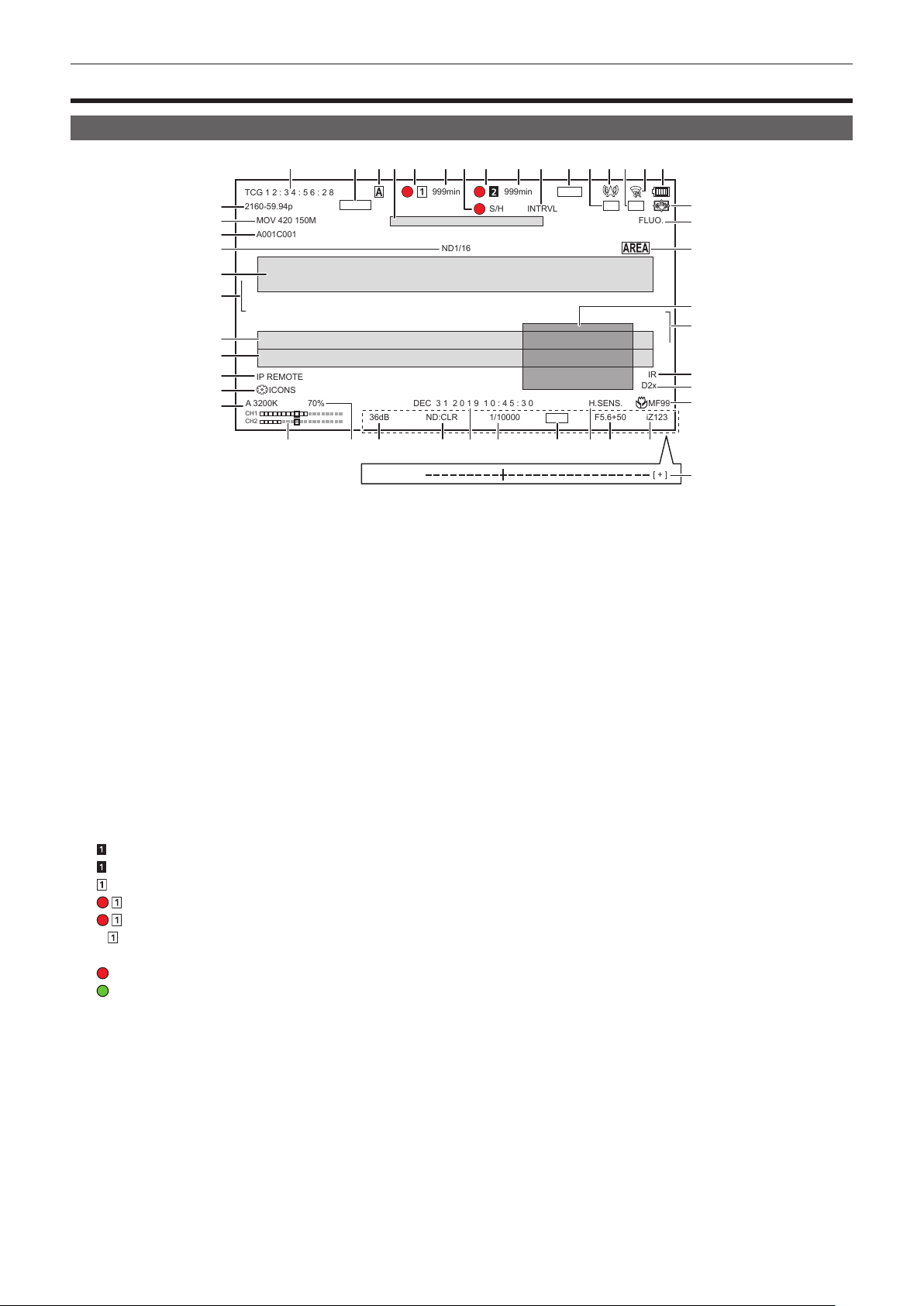
– 160 –
Chapter 7 Output and Screen Display — Screen status display
Screen status display
Screen display during shooting
TCG 1 2 : 3 4 : 5 6 : 2 8
2160‑59.94p
MOV 420 150M
A001C001
A 3200K
IP REMOTE
36dB
ND:CLR
1/10000
F5.6+50
H.SENS.
DEC 3 1 2 0 1 9 1 0 : 4 5 : 3 0
iZ123
MF99
D2x
IR
70%
S/H
INTRVL
ND1/16
FLUO.
999min
999min
S.SLOW120
FBC
RELAY
HDR
STD
CH1
CH2
[ + ]
ICONS
VOLUME [ ‑ ]
1 2 3 5 6 7 8 9 10 11 12 13
17 18 19 20 21 22 23 24 25 26
38
28
30
32
41
42
43
29
27
31
39
40
32
44
45
33
34
35
36
37
4 14
15 16
1 Time code
The display will toggle to the next display or no display every time the <COUNTER> button is pressed.
f [TCG **:**:**:**]: Displays the time code. [TCR **:**:**:**] will be displayed during playback.
[TCG] is displayed with black and white inverted during the slave lock into the external input time code.
f [UBG ** ** ** **]: Displays the user bits. [UBR ** ** ** **] will be displayed during playback.
f [CLIP *:**:**:**]: Displays the counter value of each clip. This is displayed when the [RECORDING] menu → [REC COUNTER] is set to
[CLIP]. Displays the counter value of the clip being played back during playback.
f [*:**:**:**]: Displays the cumulative counter value from the reset position. This is displayed when the [RECORDING] menu → [REC
COUNTER] → [TOTAL] is set.
2 Frame rate
f [**fps]: Frame rate is displayed when set to the [SCENE FILE] menu → [VFR] → [ON].
f [S.SLOW120]: Displayed when set to the [SYSTEM] menu → [SUPER SLOW] → [ON] and the [SYSTEM] menu → [FREQUENCY] → [59.94Hz].
f [S.SLOW100]: Displayed when set to the [SYSTEM] menu → [SUPER SLOW] → [ON] and the [SYSTEM] menu → [FREQUENCY] → [50.00Hz].
f (No display): It is not displayed when set to the [SCENE FILE] menu → [VFR] → [OFF] and the [SYSTEM] menu → [SUPER SLOW] → [OFF].
3 <AUTO/MANUAL> switch
Displayed when the <AUTO/MANUAL> switch is set to <AUTO>.
4 Message display area for stop of cooling fan
Displays a message when the cooling fan has stopped.
5 Recording status (card slot 1)
Displays the recording status of the memory card in card slot 1.
f
: Not target for recording.
f
(ashing): Recognizing the memory card.
f
: The recording is stopped while the recording target memory card is inserted.
f
: Recording.
f
(Flashing red dot): Processing to stop the recording.
f [P
]: Recording is stopped with pre-recording is enabled and the recording target memory card is inserted.
f [P]: Pre-recording is enabled, and the memory card is not inserted in the card slot, or the memory card is not recognized.
f
: The tally lamp is instructed to illuminate in red via network.
f
: The tally lamp is instructed to illuminate in green via network while the recording is stopped.
f (No display): It is in one of the following conditions.
-A memory card has not been inserted.
-The memory card cannot be recognized.
-The tally lamp is not instructed to illuminate in red/green via network, and the [NETWORK] menu → [NETWORK FUNC] → [NDI|HX] is set.
6 Remaining recording capacity and status of the memory card (card slot 1)
Displays the remaining recording capacity and status of the memory card in card slot 1.
f [0min] to [999min]: Remaining recording capacity (999 minutes or more is displayed as [999min])
-The display will ash when the remaining recording capacity becomes two minutes or less.
-The recording capacity available for simultaneous recording (recording capacity for the memory card of the two memory cards with less recording
capacity) is displayed when simultaneous recording is performed.
f [WP]: Write protected (the write protection switch of the memory card is set to the LOCK side)
f [END]: No remaining recording capacity (no remaining recording capacity on the memory card)
f [ERR]: A memory card that cannot record is inserted (the card is recognized but cannot record due to a format error, a card other than a memory
card being inserted, etc.)

– 161 –
Chapter 7 Output and Screen Display — Screen status display
f [!SDXC]: The SDXC memory card is not inserted for MOV recording
f (No display): It is in one of the following conditions.
-A memory card has not been inserted.
-The memory card cannot be recognized.
-The [NETWORK] menu → [NETWORK FUNC] → [NDI|HX] is set.
7 External equipment recording operation control status (<SDI OUT>/<HDMI> terminal)
Displays the control status of the recording start and recording stop on the external equipment connected to the <SDI OUT> terminal and the
<HDMI> terminal.
f [
S/H]: Recording instruction is output to the output from the <SDI OUT> terminal and <HDMI> terminal.
f [S/H]: Pause instruction is output to the output from the <SDI OUT> terminal and <HDMI> terminal.
f [
SDI]: Recording instruction is output to the output from the <SDI OUT> terminal.
f [SDI]: Pause instruction is output to the output from the <SDI OUT> terminal.
f [
HDMI]: Recording instruction is output to the output from the <HDMI> terminal.
f [HDMI]: Pause instruction is output to the output from the <HDMI> terminal.
8 Recording status (card slot 2)
Displays the recording status of the memory card in card slot 2.
f
: Not target for recording.
f
(ashing): Recognizing the memory card.
f
: The recording is stopped while the recording target memory card is inserted.
f
: Recording.
f
(Flashing red dot): Processing to stop the recording.
f [P
]: Recording is stopped with pre-recording is enabled and the recording target memory card is inserted.
f (No display): It is in one of the following conditions.
-A memory card has not been inserted.
-The memory card cannot be recognized.
-The [NETWORK] menu → [NETWORK FUNC] → [NDI|HX] is set.
9 Remaining recording capacity and status of the memory card (card slot 2)
Displays the remaining recording capacity and status of the memory card in card slot 2.
f [0min] to [999min]: Remaining recording capacity (999 minutes or more is displayed as [999min])
-The display will ash when the remaining recording capacity becomes two minutes or less.
-The recording capacity available for simultaneous recording (recording capacity for the memory card of the two memory cards with less recording
capacity) is displayed when simultaneous recording is performed.
f [WP]: Write protected (the write protection switch of the memory card is set to the LOCK side)
f [END]: No remaining recording capacity (no remaining recording capacity on the memory card)
f [ERR]: A memory card that cannot record is inserted (the card is recognized but cannot record due to a format error, a card other than a memory
card being inserted, etc.)
f [!SDXC]: The SDXC memory card is not inserted for MOV recording
f (No display): It is in one of the following conditions.
-A memory card has not been inserted.
-The memory card cannot be recognized.
-The [NETWORK] menu → [NETWORK FUNC] → [NDI|HX] is set.
10 Special recording function
Displays the status of special recording function.
f [INTRVL]: The interval recording is stopped.
f [I-REC]: The interval recording is in progress. (Displayed in red)
11 Two-slot function
Displays the setting status of the recording function using two memory cards.
It is displayed with a slanted line if it is in a condition that cannot perform two-slot recording even if each function is enabled.
f [RELAY]: When the relay recording is enabled
f [SIMUL]: When the simultaneous recording is enabled
f [BACKGR]: When the background recording is enabled
f (No display): During standard recording (when set to the [NETWORK] menu → [NETWORK FUNC] → [NDI|HX], [NDI|HX] is displayed)
12 Flash band compensation function
f [FBC]: Displayed when the ash band compensation function is operating.
13 Streaming status
Displays the streaming status.
f
: When the camera is connected to a device to receive the streaming video, and the streaming video is distributed
f
(ashing): When the camera is being connected to a device to receive the streaming video
f
: When the streaming function is enabled, it is in condition to operate properly, and the streaming video is not distributed
f
: When there is an error in the streaming function and cannot operate
f (No display): When the streaming function is disabled
14 High dynamic range recording function/dynamic range stretcher function
f [HDR]: When set to the [SCENE FILE] menu → [GAMMA MODE SEL] → [HLG]
f [DRS]: When the dynamic range stretcher function is operating
15 Connection status of the wireless LAN/wired LAN
Displays the connection status of the wireless LAN or wired LAN.
f
: When set to the wireless LAN and the ROP is not connected

– 162 –
Chapter 7 Output and Screen Display — Screen status display
f
: When set to the wireless LAN and the ROP is connected
f
: When set to the wireless LAN and the wireless LAN is not operating properly
f
: When set to the wired LAN and the ROP is not connected
f
: When set to the wired LAN and the ROP is connected
f
: When set to the wired LAN and the wired LAN is not operating properly
f (No display): When both the wireless LAN and the wired LAN are disabled
16 Power status
: Displays the remaining battery level while powered with the battery. (The battery status display will change as → → → →
→
while the remaining battery level gets lower. It will ash in red when the remaining battery level is zero.)
: Displayed when powered with the AC adaptor.
17 Audio level meter
Displays the audio level meter.
When P2 or MOV is set as the recording format, the audio channel displayed in the audio level meter follows the setting in the [AUDIO] menu →
[OUTPUT SETTINGS] → [AUDIO OUT].
f Displays the audio channel 1 and audio channel 2 when set to [CH1]/[CH2]/[CH1/2 STEREO]/[CH1/2 MIX].
f Displays the audio channel 3 and audio channel 4 when set to [CH3]/[CH4]/[CH3/4 STEREO]/[CH3/4 MIX].
f Switches the audio channel to display in the audio level meter (audio channel 1/2 and audio channel 3/4) while the USER button to which [AUDIO
MON SEL] is assigned is pressed or the USER button icon is touched.
A white frame is displayed at the position of the reference level set in the [AUDIO] menu → [REC CH SETTINGS] → [HEAD ROOM]. (Eighth from
the left when set to [20dB], ninth from the left when set to [18dB], and 12th from the left when set to [12dB])
f
: Displayed when audio cannot be recorded. (Such as when the variable frame rate recording function is enabled, and the frame rate is set
different from the system frequency.)
18 Luminance of Y GET
Displays the luminance level in 0% through 109% when the Y GET function is operating.
19 Gain
Displays the gain value.
f [AGC]: Displayed when the auto gain control is operating.
20 ND lter
Displays the transmittance of the selected ND lter.
f [ND1/64]: Reduces the amount of light entering the MOS sensor to 1/64.
f [ND1/16]: Reduces the amount of light entering the MOS sensor to 1/16.
f [ND1/4]: Reduces the amount of light entering the MOS sensor to 1/4.
f [ND:CLR]: The ND lter is not used.
21 Date and time information
Displays the date and time information. It is not displayed when the time stamp function is enabled.
The display contents follow the setting in the [VIDEO OUT/LCD/VF] menu → [INDICATOR] → [DATE/TIME]. (page 87)
The display order for the year, month, and date follows the setting in the [OTHERS] menu → [CLOCK] → [DATE FORMAT].
Displays in the yyyy mmm dd hh:mm:ss format when set to [Y-M-D].
Displays in the mmm dd yyyy hh:mm:ss format when set to [M-D-Y].
Displays in the dd mmm yyyy hh:mm:ss format when set to [D-M-Y].
f mmm: Month (JAN (January), FEB (February), MAR (March), APR (April), MAY (May), JUN (June), JUL (July), AUG (August), SEP (September),
OCT (October), NOV (November), DEC (December))
f dd: Date
f yyyy: Year
f hh: Hour
f mm: Minute
f ss: Second
22 Shutter speed
Displays the shutter speed.
Display of [sec] and [deg] can be switched with the [SCENE FILE] menu → [SYNC SCAN TYPE] during synchro scan. Displayed in time (minutes)
display when set to [sec], and in aperture angle when set to [deg].
It is not displayed when the shutter function is disabled.
f [A.SHTR]: Displayed when the auto shutter is operating.
23 Auto iris control status
Displays the control status of the auto iris.
f [STD]: Standard auto iris control
f [SPOT]: Auto iris control for spot light
f [BACK]: Auto iris control for the backlight compensation
24 High-sensitivity mode
f [H.SENS.]: Displayed when set to the [SYSTEM] menu → [SHOOTING MODE] → [HIGH SENS.].
25 Iris
Displays the F value.
Displays the target value of the auto iris level when the auto iris level function is enabled in the auto iris.

– 163 –
Chapter 7 Output and Screen Display — Screen status display
26 Zoom
Displays the zoom value.
The display of the zoom value follows the setting in the [VIDEO OUT/LCD/VF] menu → [INDICATOR] → [ZOOM/FOCUS].
Displays in the position value from [000] to [999] when set to [NUMBER].
Displays in millimeter unit when set to [mm/feet] or [mm/m].
Displays [i] when i.ZOOM is enabled.
[i] is displayed with black and white inverted when i.ZOOM is operating.
[Z] is displayed with black and white inverted when [FAST ZOOM] is enabled.
27 System resolution/system frequency
Displays the system resolution and the system frequency set in the [SYSTEM] menu → [REC FORMAT].
f [2160-59.94p]
f [2160-50.00p]
f [2160-29.97p]
f [2160-25.00p]
f [2160-23.98p]
f [1080-59.94p]
f [1080-50.00p]
f [1080-29.97p]
f [1080-25.00p]
f [1080-23.98p]
f [1080-59.94i]
f [1080-50.00i]
f [720-59.94p]
f [720-50.00p]
f [480-59.94i]
f [576-50.00i]
28 Recording format
Displays the le format and the recording codec set in the [SYSTEM] menu → [FILE FORMAT] and [REC FORMAT].
It is not displayed when set to the [NETWORK] menu → [NETWORK FUNC] → [NDI|HX].
f [P2 AVC-I422]
f [P2 AVC-G50]
f [P2 AVC-G25]
f [P2 AVC-G12]
f [MOV 420 150M]
f [MOV 420 100M]
f [MOV 422 150M]
f [MOV 422 100M]
f [MOV 422 50M]
f [MOV HEVC 200M]
f [MOV HEVC 150M]
f [MOV HEVC 100M]
f [MOV ALL-I 400M]
f [MOV ALL-I 200M]
f [MOV ALL-I 100M]
f [AVCHD PS]
f [AVCHD PH]
f [AVCHD HA]
f [AVCHD PM]
f [AVCHD SA]
29 Clip name
Displays the name of the clip being recorded with up to eight characters from the beginning.
30 Recommended ND lter
Displays the ND lter recommended in the current shooting condition.
31 Message display area
Displays the message such as the camera status or the warning.
Displays the warning status of the camera in the STATUS screen for the mode check.
32 Level gauge
Tilt in horizontal direction or vertical direction can be checked.
Displayed only on the LCD monitor and the viewnder.
33 Error display of auto white balance
Displays the error status of the auto white balance.
34 Error display of auto black balance
Displays the error status of the auto black balance.
35 Remote control status in an IP connection
f [IP REMOTE]: Displayed when the remote control is possible in the IP connection.
f [IP REMOTE] (ashing): Displayed when waiting for the connection in the IP connection.
– 164 –
Chapter 7 Output and Screen Display — Screen status display
36 Multi manual function
Displays the contents of the multi manual function. For details, refer to “Multi manual function” (page 144).
37 Color temperature
Displays the position and color temperature selected with the <WHITE BAL> switch. It is not displayed when the IR recording is enabled.
f [ATW]: Displayed when the auto tracking white balance is operating.
f [LOCK]: Displayed when the auto tracking white balance is locked.
38 Optical image stabilizer function
f
: Displayed when the optical image stabilizer function is operating.
f
: Displayed when the hybrid optical image stabilizer function is operating.
39 Scene le name
Displays the name of the selected scene le.
40 Area mode function/auto focus area width adjustment function
f [AREA]: Displayed when the area mode function is operating.
f [AF AREA]: Displayed when the auto focus area width adjustment function is operating.
41 Waveform monitor
Displays the video status in waveform or vector.
Displayed only on the LCD monitor and the viewnder.
42 IR recording
f [IR]: Displayed when the IR recording is enabled.
43 Digital zoom
Displays the digital zoom ratio.
f [D2×]: Two times
f [D5×]: Five times
f [D10×]: Ten times
44 Focus
Displays the focus value.
The display of the focus value follows the setting in the [VIDEO OUT/LCD/VF] menu → [INDICATOR] → [ZOOM/FOCUS].
Displays in the position value from [00] to [99] when set to [NUMBER].
Displays in feet unit when set to [mm/feet].
Displays in meter unit when set to [mm/m].
f
: Displayed when the focus macro is enabled.
f [AF]: Displayed when set to auto focus. Displayed with black and white inverted when focus macro is operating.
f [MA]: Displayed when the manual focus assist is enabled in the manual focus. Displayed with black and white inverted when focus macro is
operating.
f [MF]: Displayed when the manual focus assist is disabled in the manual focus. Displayed with black and white inverted when focus macro is
operating.
45 Audio monitor volume adjustment
Displayed when the <AUDIO MON/ADV> button is operated to adjust the volume of the speaker or the headphones. The display is cleared
approximately three seconds after the operation.
Screen display during playback
TCR 12:59:59:23
A001C001
3
5
6
1 2
4
CH1
CH2
1 Time code display
Every time the <COUNTER> button is pressed, the display is toggled in the order of [TCR **:**:**:**], [UBR ** ** ** **],
[CLIP *:**:**:**], and no display.
2 Clip name
Displays the name of the clip being played back with up to eight characters from the beginning.
3 Playback status
Displays the status of playback.
Displays only during playback.
– 165 –
Chapter 7 Output and Screen Display — Screen status display
f : Stop
f
: Playback
f
: Pause
f
: Frame-by-frame rewind
f
: Frame-by-frame
f
: Fast-forward playback (10x speed)
f
: Fast-forward playback (20x speed)
f
: Fast-reverse playback (10x speed)
f
: Fast-reverse playback (20x speed)
f
: Slow playback
f
: Reverse slow playback
4 Still picture recording icon
Touching the icon while playing back or while paused records the scene as a still picture.
5 Direct playback bar
Displays the general position that is being played back.
6 Playback navigation icon
Operates by touching the icon.
f
: Fast-forward playback
f
: Fast-reverse playback
f
: Stop
f
/ : Playback/pause
Checking and displaying shooting status
The screen to check the setting and status of the camera can be displayed.
Press the <DISP/MODE CHK> button while the camera image screen is displayed to hide most of the items.
Press the <DISP/MODE CHK> button for one second or more while the camera image screen is displayed to display the STATUS screen of the mode
check and check the shooting status.
For details about each item that can be displayed in the mode check, refer to “Mode check display” (page 166).
The following table indicates each item to display/hide in each screen.
f “l” indicates displaying and “—” indicates hiding.
f You can select to display or hide each item in the [VIDEO OUT/LCD/VF] menu → [INDICATOR].
No Item
Camera image
screen
When the <DISP/
MODE CHK> button
is pressed
STATUS Playback screen
1 Time code
l l l l
2 Frame rate
l
—
l
—
3 <AUTO/MANUAL> switch
l
—
l
—
4 Message display area for stop of cooling fan
l l l l
5 Recording status (card slot 1)
l l*
1
l
—
6 Remaining recording capacity and status of the
memory card (card slot 1)
l
—*
2
l
—
7 External equipment recording operation control
status (<SDI OUT>/<HDMI> terminal)
l
—
l
—
8 Recording status (card slot 2)
l l*
1
l
—
9 Remaining recording capacity and status of the
memory card (card slot 2)
l
—*
2
l
—
10 Special recording function
l
—
l
—
11 Two‑slot function
l
—
l
—
12 Flash band compensation function
l
—
l
—
13 Streaming status
l
—
l
—
14 High dynamic range recording function/dynamic
range stretcher function
l
—
l
—
15 Connection status of the wireless LAN/wired
LAN
l
—
l
—
16 Power status
l
—*
2
l l
17 Audio level meter
l
—
l l
18 Luminance of Y GET
l l l
—
19 Gain
l
—
l
—
20 ND lter
l
—
l
—
21 Date and time information
l
—
l
—
22 Shutter speed
l
—
l
—
23 Auto iris control status
l
—
l
—
24 High-sensitivity mode
l
—
l
—
25 Iris
l
—
l
—
– 166 –
Chapter 7 Output and Screen Display — Screen status display
No Item
Camera image
screen
When the <DISP/
MODE CHK> button
is pressed
STATUS Playback screen
26 Zoom
l
—
l
—
27 System resolution/system frequency
l
—
l
—
28 Recording format
l
—
l
—
29 Clip name
l
—
l l*
3
30 Recommended ND lter
l l l
—
31 Message display area
l l l l
32 Level gauge
l l l
—
33 Error display of auto white balance — —
l
—
34 Error display of auto black balance — —
l
—
35 Remote control status in an IP connection — —
l
—
36 Multi manual function
l
—*
4
l
—
37 Color temperature
l
—
l
—
38 Optical image stabilizer function
l
—
l
—
39 Scene le name
l
—
l
—
40 Area mode function/auto focus area width
adjustment function
l
—
l
—
41 Waveform monitor
l l
— —
42 IR recording
l
—
l
—
43 Digital zoom
l
—
l
—
44 Focus
l
—
l
—
45 Audio monitor volume adjustment
l l l l
*1 This is not displayed in the status where
/ is not displayed.
*2 Displays when the remaining recording capacity of the memory card or remaining battery level gets low.
*3 The display position differs in the playback screen. Refer to Screen display during playback (page 164).
*4 Displays when the multidial, <=/&> button, <(> button, or <SET> button is pressed. The display is cleared approximately three seconds after the operation.
Mode check display
The camera settings and status can be displayed on the viewnder or LCD monitor screen for check.
Press the <DISP/MODE CHK> button for one second or more while displaying the camera image screen to display the STATUS screen of the mode
check.
The display toggles in the order of the STATUS screen, FUNCTION screen, AUDIO screen, SWITCH screen, NETWORK screen and the camera image
screen each time the <DISP/MODE CHK> button is pressed.
Each screen of the mode check is displayed for approximately ve seconds.
The screen does not switch while the <DISP/MODE CHK> button is pressed.
Press the <EXIT> button while each screen is displayed to return to the camera image screen.
FUNCTION screen
Displays the video output settings and information of the recording media.
Item Description
[VIDEO OUT] [VIDEO OUT SEL] Displays the output destination of the video and audio with [SDI + HDMI]/[AV +
HDMI].
[SDI OUT FORMAT]/[AV OUT
FORMAT]
Displays as follows depending on the setting for the output destination of video
and audio.
f When set to [SDI + HDMI]:
The signal output from the <SDI OUT> terminal is displayed with
[1920×1080p][1920×1080i]/[1920×1080PsF]/[1280×720p]/[720×480i]/
[720×576i].
f When set to [AV + HDMI]:
The signal output from the <AV OUT> terminal is displayed with [720×480i]/
[720×576i].
[SDI OUT CHAR]/[AV OUT CHAR] Displays as follows depending on the setting for the output destination of video
and audio.
f When set to [SDI + HDMI]:
Displays whether to superimpose the character to the output from the <SDI
OUT> terminal with [ON]/[OFF].
f When set to [AV + HDMI]:
Displays whether to superimpose the character to the output from the <AV
OUT> terminal with [ON]/[OFF].
[HDMI OUT FORMAT]
The signal output from the <HDMI> terminal is displayed with [3840×2160p]/
[3840×2160p(420/8bit)]/[1920×1080p]/[1920×1080i]/[1280×720p]/[720×480p]/
[720×576p].
[HDMI OUT CHAR] Displays whether to superimpose the character to the output from the <HDMI>
terminal with [ON]/[OFF].

– 167 –
Chapter 7 Output and Screen Display — Screen status display
Item Description
[HDR/SDR] [SDI OUT]/[AV OUT] Displays as follows depending on the setting for the output destination of video
and audio.
f When set to [SDI + HDMI]:
The output image from the <SDI OUT> terminal is displayed with [HDR]/
[SDR].
f When set to [AV + HDMI]:
The output image from the <AV OUT> terminal is displayed with [SDR].
[HDMI OUT] The output image from the <HDMI> terminal is displayed with [HDR]/[SDR].
[LCD/VF] Displays the output image from the LCD monitor and the viewnder with [HDR]/
[SDR].
[CARD STATUS] — Displays the status, remaining recording capacity, and the total capacity of the
memory card inserted in the card slot.
It is not displayed when set to the [NETWORK] menu → [NETWORK FUNC] →
[NDI|HX].
The status of the memory card that is displayed are following types.
f [NO CARD]: Memory card is not inserted.
f [UNSUPPORTED]: Memory card is not supported.
f [FORMAT ERROR]: Memory card cannot be used. (Format error)
f [PROTECTED]: It is write protected. (The write-protection switch of the
memory card is set to the LOCK side)
f [NO REMAIN]: There is no remaining recording capacity.
f [NOT SDXC]: SDXC memory card is not inserted in the MOV recording.
f Cases other than above: The remaining recording capacity is displayed in 0%
through 100%.
[TOTAL] Displays the remaining recording capacity/total capacity of the memory cards in
the card slot 1 and the card slot 2.
[SLOT1] Displays the status and remaining recording capacity/total capacity of the
memory card in card slot 1.
[SLOT2] Displays the status and remaining recording capacity/total capacity of the
memory card in card slot 2.
AUDIO screen
Displays the audio input/output settings and the audio level meter.
When P2 or MOV is set as the recording format, the audio channel displayed in the audio level meter follows the setting in the [AUDIO] menu →
[OUTPUT SETTINGS] → [AUDIO OUT].
f Displays the audio channel 1 and audio channel 2 when set to [CH1]/[CH2]/[CH1/2 STEREO]/[CH1/2 MIX].
f Displays the audio channel 3 and audio channel 4 when set to [CH3]/[CH4]/[CH3/4 STEREO]/[CH3/4 MIX].
f Switches the audio channel to display in the audio level meter (audio channel 1/2 and audio channel 3/4) while the USER button to which [AUDIO
MON SEL] is assigned is pressed or the USER button icon is touched.
Item Description
[AUDIO] [AUDIO OUT] Displays the audio channel and the format output from the <AV OUT> terminal,
headphone terminal, and the built-in speaker with [CH1]/[CH2]/[CH1/2
STEREO]/[CH1/2 MIX]/[CH3]/[CH4]/[CH3/4 STEREO]/[CH3/4 MIX].
[SELECT] [CH1] - [CH4] The audio to be recorded in each channel is displayed with [INT(L)]/[INT(R)]/
[INPUT1]/[INPUT2].
[LINE/MIC] [CH1] - [CH4] The audio input signal of each channel is displayed with [LINE]/[MIC]/
[MIC+48V].
Displays [---] when [INT(L)] or [INT(R)] is selected as the audio to be recorded.
[LEVEL] [CH1] - [CH4] Displays the adjustment method of the recording level of the audio for each
channel with [AUTO]/[MANU].
[LIMITER] [CH1] - [CH4] Displays enable/disable of limiter for each channel with [ON]/[OFF].
Displays [---] when the adjustment method of the recording level of the audio is
set to [AUTO].
[LOWCUT] [CH1] - [CH4] Displays enable/disable of low-cut lter for each channel with [ON]/[OFF].
SWITCH screen
Displays the function assigned to the USER switch, <GAIN> switch, and <WHITE BAL> switch as well as the setting value.
Item Description
[USER SW] [1] - [7] Displays the function assigned to <USER 1> through <USER 7> buttons.
[OTHER ASSIGN] [GAIN L] Displays the gain value assigned to the <L> position of the <GAIN> switch.
[GAIN M] Displays the gain value assigned to the <M> position of the <GAIN> switch.
[GAIN H] Displays the gain value assigned to the <H> position of the <GAIN> switch.
[S.GAIN] Displays the list of gain values assigned as a super gain.
[WHITE BAL A] Displays the color temperature assigned to the <A> position of the <WHITE
BAL> switch.
Displays [ATW] when the auto tracking white balance function is assigned.

– 168 –
Chapter 7 Output and Screen Display — Screen status display
Item Description
[WHITE BAL B] Displays the color temperature assigned to the <B> position of the <WHITE
BAL> switch.
Displays [ATW] when the auto tracking white balance function is assigned.
[WHITE BAL PRST] Displays the color temperature assigned to the <PRST> position of the
<WHITE BAL> switch.
Displays [ATW] when the auto tracking white balance function is assigned.
Color temperature and [VAR] are displayed when [VAR] is assigned.
NETWORK screen
Displays the settings of the network function.
Item Description
[NETWORK] [DEVICE SEL] Displays the device that connects an external equipment (computer, etc.) and
the camera with [LAN]/[WLAN]/[OFF].
[NETWORK FUNC]
Displays the network function of the camera with [STREAMING]/[NDI|HX]/
[OFF].
[STRM FORMAT] Displays the streaming format.
It is not displayed when set to the [NETWORK] menu → [NETWORK FUNC]
→ [OFF].
[STRM DATA TYPE] Displays the type of the streaming connection information.
It is not displayed when set to anything other than the [NETWORK] menu →
[NETWORK FUNC] → [STREAMING].
[IP REMOTE] Displays enable/disable of the IP remote function with [ENABLE]/[DISABLE].
[IPv4 ADDRESS] Displays the IP address of IPv4.
It is not displayed when set to the [NETWORK] menu → [DEVICE SEL] →
[OFF].
[IPv6 ADDRESS] Displays the IP address of IPv6.
[DISABLE] is displayed when the [NETWORK] menu → [LAN PROPERTY] →
[IPv6 SETTING] → [ENABLE/DISABLE] → [DISABLE] is set.
It is not displayed when set to anything other than the [NETWORK] menu →
[DEVICE SEL] → [LAN].

This chapter describes the external devices that can be connected to the camera.
Chapter 8 Connecting to External Devices
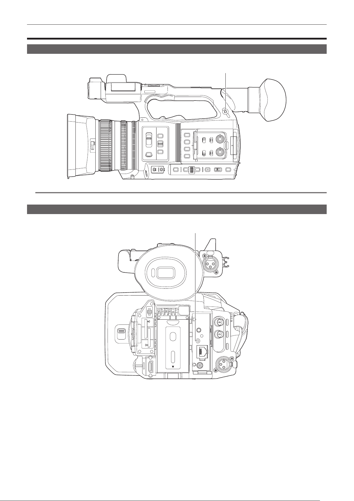
– 170 –
Chapter 8 Connecting to External Devices — Connecting with headphones and TV/monitor
Connecting with headphones and TV/monitor
Headphones
Headphones (optional) can be connected to the headphone terminal (3.5 mm stereo mini jack).
Headphone terminal
@
NOTE
t Audio is not output from the built-in speaker when headphones are connected to the headphone terminal.
Remote control
Connect the remote control unit (optional) to the <REMOTE> terminal (2.5 mm diameter super mini jack) to operate some of the functions remotely.
<REMOTE> terminal
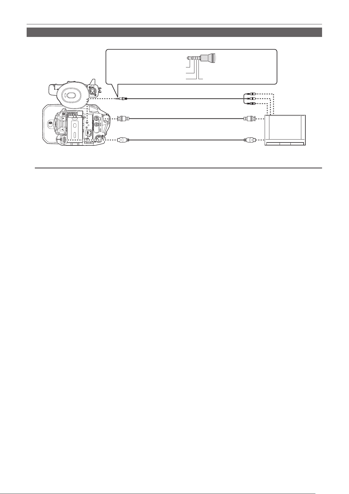
– 171 –
Chapter 8 Connecting to External Devices — Connecting with headphones and TV/monitor
TV/monitor
A TV or monitor can be connected as shown in the following gure.
TV/monitor
BNC cable (optional)
HDMI cable (optional)
3.5 mm diameter video/audio cord 4-pole mini plug:
Commercial product
Audio (Left audio: White)
Video (Yellow)
Ground Audio (Right audio: Red)
@
NOTE
t VIERA Link is not supported on the camera. Note that the VIERA Link of other device may not properly operate when connected to the VIERA Link
compatible device with a HDMI cable (optional).
t The SD resolution signal output from the <HDMI> terminal is output as a progressive signal (480P, 576P).
t For the BNC cable (optional) connected to the <SDI OUT> terminal, prepare a double-shielded cable equivalent to 5C-FB.
t Use the double shielded cable supporting 4K/60P as the HDMI cable (optional). Also, it is recommended to use the Panasonic HDMI cable compatible
to 4K/60P as the HDMI cable.

– 172 –
Chapter 8 Connecting to External Devices — Connection function via the <USB3.0 DEVICE>/<USB2.0 HOST> terminal
Connection function via the <USB3.0 DEVICE>/<USB2.0 HOST> terminal
Connection with a computer in card reader mode
Connect the camera to a computer via the USB type C cable to use the camera as a card reader for the memory card.
Connecting to a computer
USB type C cable (optional)
Computer
Type C
1
Connect the USB cable to the <USB3.0 DEVICE> terminal.
2
Select the [OTHERS] menu → [USB DEVICE] → [CARD READER MODE].
3
Select [YES] when the confirmation message is displayed.
During USB connection, [USB connected. Please operate via PC.] is displayed in the center of the viewnder or LCD monitor.
If the USB connection is being moved or it is not connected properly, [Connect this unit to PC using USB cable.] is displayed.
4
Exit the card reader mode.
There are following methods.
f Turn the power switch of the camera to < h > (standby).
f Press the <EXIT> button.
After exiting the card reader mode, returns to camera shooting status in approximately ve seconds.
@
NOTE
t A USB type C cable is not supplied with this camera. Prepare a commercial USB type C cable (double-shielded for noise suppression).
t Using a USB cable within 1.5 m as much as possible is recommended.
t When connecting the camera to a computer via USB, ensure that no other device is connected to the computer via USB.
t Do not remove the memory card when connecting the camera via USB.
t The card access lamp while connected to USB will turn off unless accessing.
t When the camera is operating in the card reader mode, camera shooting, recording/playback operation, or thumbnail operation of the clip is not
allowed.
t When the camera is operating in the card reader mode, the remaining recording capacity and status of the memory card are not displayed. Also,
video/audio cannot be output or displayed.
t The LCD monitor lights up by touching the monitor if it has turned out to save energy.

– 173 –
Chapter 8 Connecting to External Devices — Remote operation by iPhone/iPad or Android terminal
Remote operation by iPhone/iPad or Android terminal
The camera can be connected to the wireless LAN by connecting a wireless module (optional) compatible to the camera to the <USB2.0 HOST>
terminal of camera.
Some of the functions can be remotely operated by connecting the camera with iPhone/iPad or Android terminal with the CX ROP app installed.
(page 182)

This chapter describes how to use the camera by connecting to a network.
Chapter 9 Network Connection
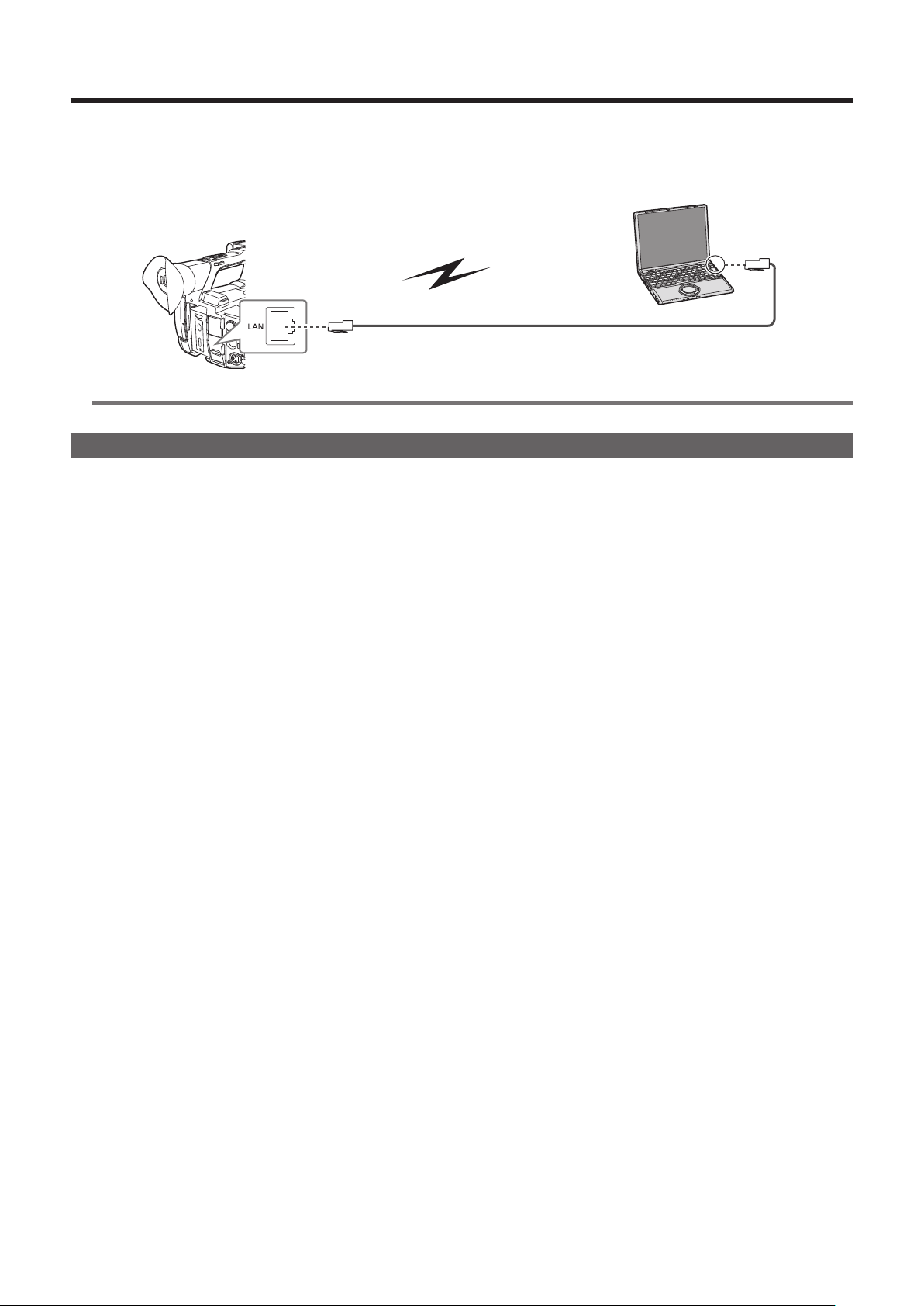
– 175 –
Chapter 9 Network Connection — Network connection
Network connection
The camera can be connected to a network via a wireless LAN or wired LAN.
For details on wireless modules that can be connected, refer to the support desk at the following website:
https://pro-av.panasonic.net/
Attach the wireless module (optional) to the <USB2.0 HOST> terminal to use a wireless LAN.
Connect a LAN cable to the <LAN> terminal on the rear side to use wired LAN.
1000BASE-T/100BASE-TX/10BASE-T
IEEE802.11a/g/n/ac
@
NOTE
t For the cable to be connected to the <LAN> terminal, use Category 6 or higher LAN cable.
Available functions
When the camera is connected to a network, the following functions are available.
f Connecting to CX ROP application
f Streaming function
f NDI|HX function
f P2 Cast link
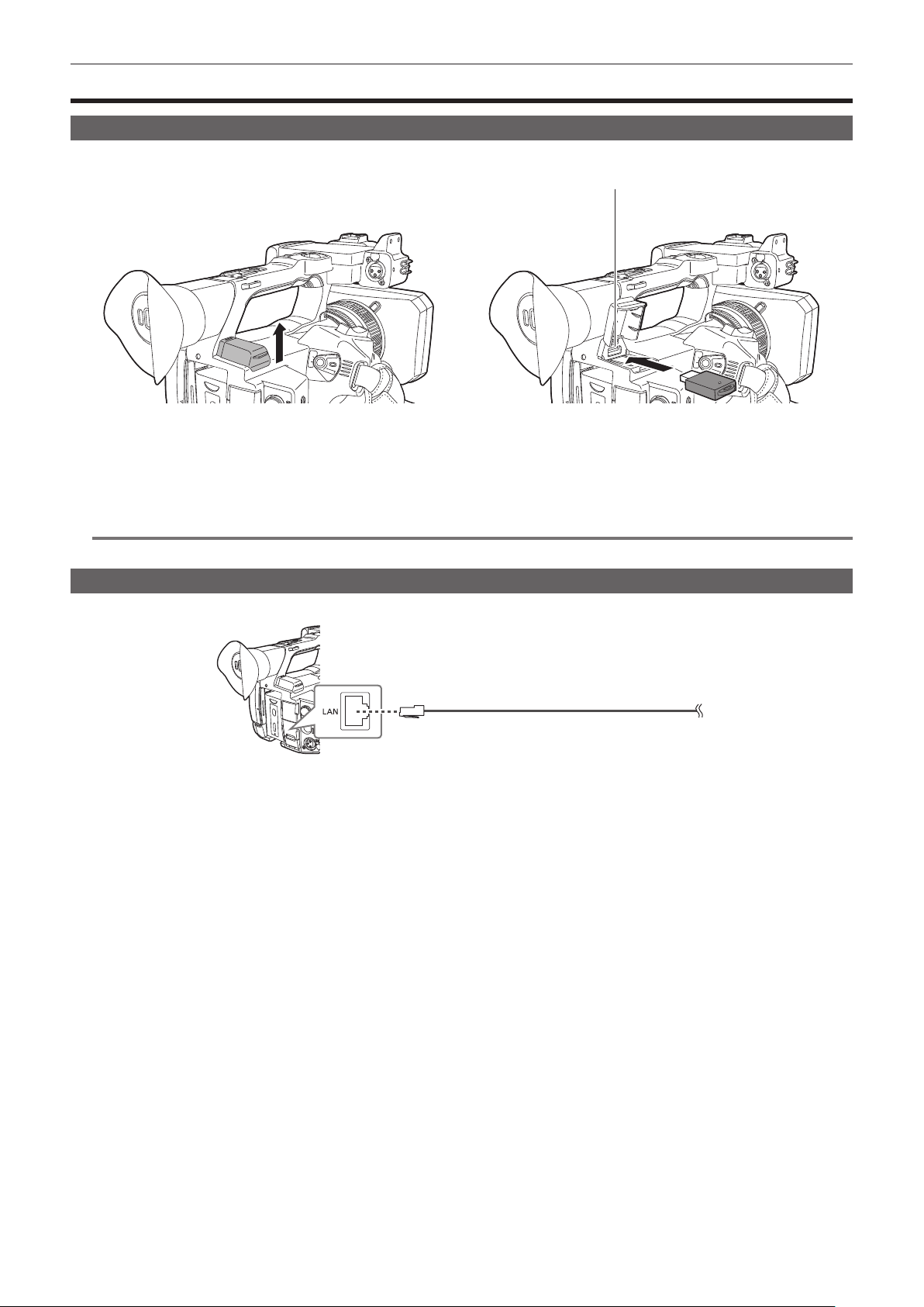
– 176 –
Chapter 9 Network Connection — Preparing for connection
Preparing for connection
For the wireless module
Mount the wireless module (optional) to the camera.
Fig. 1
<USB2.0 HOST> terminal
Fig. 2
1
Open the <USB2.0 HOST> terminal cover on the top-back side. (Fig. 1)
2
Connect the wireless module to the <USB2.0 HOST> terminal. (Fig. 2)
Insert it all the way.
@
NOTE
t When removing the wireless module, pull it out straight.
For the wired LAN
Connect a LAN cable.
1000BASE-T/100BASE-TX/10BASE-T
1
Insert the LAN cable into the <LAN> terminal on the rear side.

– 177 –
Chapter 9 Network Connection — Network settings
Network settings
Wireless LAN settings
This is the setting to connect with the iPhone/iPad or the Android terminal directly or to connect to the wireless access point via wireless LAN.
Direct connection ([DIRECT])
This is the setting to connect the camera to the iPhone/iPad or Android terminal directly.
The camera may restart if necessary when the setting is changed.
1
Select the [NETWORK] menu → [DEVICE SEL] → [WLAN].
2
Select the [NETWORK] menu → [WLAN PROPERTY] → [TYPE] → [DIRECT].
3
In the [NETWORK] menu → [WLAN PROPERTY], set each item as necessary.
f For details about the settings, refer to “Setting items in [WLAN PROPERTY] when set to [DIRECT]” (page 177).
4
Select the SSID of the camera from the SSID list in the iPhone/iPad or Android terminal, and enter the password (encryption key).
Display the wireless access point list screen in wireless LAN setting, and select SSID of the camera.
f Factory setting: [AG-CX350]/[AJ-UPX360]
When the password conrmation screen appears, enter the password (encryption key).
For details, refer to the operating instruction of the iPhone/iPad or Android terminal.
f Factory setting: [01234567890123456789abcdef]
5
Close the menu or return to the level of the [NETWORK] menu.
6
Check the network connection.
Once connected,
is displayed on the screen of the camera.
r Setting items in [WLAN PROPERTY] when set to [DIRECT]
[SSID] Network name of the camera (SSID)
(Factory setting: [AG-CX350]/[AJ-UPX360])
[BAND] Setting to switch between two communication method ([2.4GHz] or [5GHz])
(Factory setting: [2.4GHz])
[CHANNEL(2.4GHz)] Channel to be used when [BAND] is set to [2.4GHz]
(Factory setting: [AUTO])
[CHANNEL(5GHz)] Channel to be used when [BAND] is set to [5GHz]
(Factory setting: [AUTO])
[ENCRYPT KEY] WPA2 encryption key
(Factory setting: [01234567890123456789abcdef])
[IPv4 SETTING] [DHCP] Setting the DHCP function
f [OFF]: Does not use DHCP.
f [CLIENT]: Automatically acquired with the DHCP when connected by setting
[TYPE] to [INFRA(SELECT)] or [INFRA(MANUAL)]. (Cannot be selected.)
f [SERVER]: Enables the DHCP server function of the camera when
connecting with [TYPE] set to [DIRECT].
(Factory setting: [OFF])
[IP ADDRESS] IP address of the camera
(Factory setting: [192.168.0.1])
[SUBNET MASK] Subnet mask
(Factory setting: [255.255.255.0])
@
NOTE
t The startup time after turning on the power may be longer due to starting of the network.
t When changing the settings of [DEVICE SEL], the changes will not be reected until the camera is restarted. Also, the setting screen termination may
take some time due to the restart of the network service after the setting is changed.
t Some of the items not included in the table cannot be set.
t [ENCRYPTION] will be xed to [WPA2-AES].
t Depending on the used wireless module, some of the items in [BAND], [CHANNEL(2.4GHz)], and [CHANNEL(5GHz)] may not be able to select.
Connecting to the wireless access point ([INFRA(SELECT)]/[INFRA(MANUAL)])
This is the setting to connect the camera to a wireless access point.
When connecting by searching the wireless access point (SSID)
1
Select the [NETWORK] menu → [DEVICE SEL] → [WLAN].
2
Select the [NETWORK] menu → [WLAN PROPERTY] → [TYPE] → [INFRA(SELECT)].
3
In the [NETWORK] menu → [WLAN PROPERTY], set each item as necessary.
f For details about the setting items, refer to “[WLAN PROPERTY] setting items when set to [INFRA(SELECT)] or [INFRA(MANUAL)]” (page 178).
– 178 –
Chapter 9 Network Connection — Network settings
4
Select the SSID of the searched wireless access point.
Setting is completed when the [ENCRYPT KEY] (encryption key, password) is not set.
5
If the [ENCRYPT KEY] is set, enter the password, and select [Enter].
6
Close the menu or return to the level of the [NETWORK] menu.
7
Check the network connection.
Once connected,
is displayed on the screen of the camera.
When entering the wireless access point (SSID) manually
1
Select the [NETWORK] menu → [DEVICE SEL] → [WLAN].
2
Select the [NETWORK] menu → [WLAN PROPERTY] → [TYPE] → [INFRA(MANUAL)].
3
In the [NETWORK] menu → [WLAN PROPERTY], set each item as necessary.
f For details about the setting items, refer to “[WLAN PROPERTY] setting items when set to [INFRA(SELECT)] or [INFRA(MANUAL)]” (page 178).
4
In the [NETWORK] menu → [WLAN PROPERTY] → [SSID], enter the SSID of the wireless access point to connect.
Setting is completed when the [ENCRYPT KEY] (encryption key, password) is not set.
5
If the [ENCRYPT KEY] is set, enter the password, and select [Enter].
6
Close the menu or return to the level of the [NETWORK] menu.
7
Check the network connection.
Once connected,
is displayed on the screen of the camera.
r [WLAN PROPERTY] setting items when set to [INFRA(SELECT)] or [INFRA(MANUAL)]
[ENCRYPTION] [WPA-TKIP], [WPA-AES], [WPA2-TKIP], [WPA2-AES], [NONE]
(Factory setting: [WPA2-AES])
[ENCRYPT KEY] WPA/WPA2 encryption key
(Factory setting: [01234567890123456789abcdef])
[IPv4 SETTING] [DHCP] Setting the DHCP function
f [OFF]: Does not use DHCP.
f [CLIENT]: Automatically acquired with the DHCP when connected by setting
[TYPE] to [INFRA(SELECT)] or [INFRA(MANUAL)].
f [SERVER]: When connecting by setting [TYPE] to [DIRECT], enable the
DHCP server function of the camera. (Cannot be selected.)
(Factory setting: [OFF])
[IP ADDRESS] IP address of the camera
(Factory setting: [192.168.0.1])
[SUBNET MASK] Subnet mask
(Factory setting: [255.255.255.0])
[DEFAULT GATEWAY] Default gateway
(Factory setting: [192.168.0.254])
[PRIMARY DNS] Primary DNS server setting
(Factory setting: [0.0.0.0])
[SECONDARY DNS] Secondary DNS server setting
(Factory setting: [0.0.0.0])
@
NOTE
t The startup time after turning on the power may be longer due to starting of the network.
t When changing the settings of [DEVICE SEL], the changes will not be reected until the camera is restarted. Also, the setting screen termination may
take some time due to the restart of the network service after the setting is changed.
t ENCRYPTION in WEP is not supported.
t Some items cannot be set depending on the settings such as [DHCP].
t When [DHCP] is set to [CLIENT], some of the information acquired automatically with DHCP is displayed in the menu.
For details of the network status, conrm by selecting the [NETWORK] menu → [INFORMATION] → [STATUS].
t All of the IP address, subnet mask, and default gateway must be correctly set.
For details, contact the network administrator.
t When the default gateway or DNS is not to be used, set to [0.0.0.0].
However, DNS cannot be disabled when [DHCP] is set to [CLIENT].
t Depending on the network environment, even if [DHCP] is set to [CLIENT], entry of the DNS value manually may be required. When invalid DNS value
is entered in any other cases, the automatic assignment by DHCP will not operate properly.
Wired LAN settings
These are the settings when using a wired LAN.
1
Select the [NETWORK] menu → [DEVICE SEL] → [LAN].
2
In the [NETWORK] menu → [LAN PROPERTY], set each item as necessary.
f For details about the setting items, refer to “Setting items in [LAN PROPERTY] when set to [LAN]” (page 179).

– 179 –
Chapter 9 Network Connection — Network settings
3
Close the menu or return to the level of the [NETWORK] menu.
4
Configure the settings of the wired LAN on your device such as a computer.
For more information, refer to the operating instructions or help for the connection device.
r Setting items in [LAN PROPERTY] when set to [LAN]
[MAC ADDRESS] MAC address of the wired LAN (cannot be changed)
[IPv4 SETTING] [DHCP] Setting the DHCP function
f [OFF]: Does not use DHCP.
f [CLIENT]: Acquires automatically with DHCP.
f [SERVER]: Enables the DHCP server function of the camera.
(Factory setting: [OFF])
[IP ADDRESS] IP address of the camera
(Factory setting: [192.168.0.1])
[SUBNET MASK] Subnet mask
(Factory setting: [255.255.255.0])
[DEFAULT GATEWAY] Default gateway
(Factory setting: [192.168.0.254])
[PRIMARY DNS] Primary DNS server setting
(Factory setting: [0.0.0.0])
[SECONDARY DNS] Secondary DNS server setting
(Factory setting: [0.0.0.0])
[IPv6 SETTING] [ENABLE/DISABLE] IPv6 setting
f [ENABLE]: Uses IPv6.
f [DISABLE]: Does not use IPv6.
(Factory setting: [DISABLE])
[DHCP] Setting the DHCP function
f [OFF]: Does not use DHCP.
f [CLIENT]: Acquires automatically with DHCP.
(Factory setting: [OFF])
[IP ADDRESS] IP address of the camera
(Factory setting: [::])
[PREFIX LENGTH] Prex length settings of the subnet
(Factory setting: [64])
[DEFAULT GATEWAY] Default gateway
(Factory setting: [::])
[PRIMARY DNS] Primary DNS server
(Factory setting: [::])
[SECONDARY DNS] Secondary DNS server
(Factory setting: [::])
@
NOTE
t Some items cannot be selected depending on the settings such as [DHCP].
t The startup time after turning on the power may be longer due to starting of the network.
t When changing the settings of [DEVICE SEL], the changes will not be reected until the camera is restarted. Also, the setting screen termination may
take some time due to the restart of the network service after the setting is changed.
t All of the IP address, subnet mask, and default gateway must be correctly set.
For details, contact the network administrator.
t Set [0.0.0.0] or [::] when not using the default gateway or DNS.
However, DNS cannot be disabled when [DHCP] is set to [CLIENT].
t Depending on the network environment, even if [DHCP] is set to [CLIENT], entry of the DNS value manually may be required. When invalid DNS value
is entered in any other cases, the automatic assignment by DHCP will not operate properly.
t DHCP and DNS may not function properly depending on the network environment.
t The IP address cannot be automatically acquired depending on the connection timing with network devices if [LAN PROPERTY] → [IPv6 SETTING] →
[DHCP] → [CLIENT] is set.
In this case, reconnect the LAN cable or contact your network administrator.
Specifying the network settings using the settings tool
Camera settings
1
From the [NETWORK] menu → [UTILITY] → [EASY IP SETTING], select anything other than [DISABLE].
2
Select the [NETWORK] menu → [UTILITY] → [EASY IP CAMERA TITLE].
3
Enter the name (nickname) of the camera.
Entered name will be the name to be displayed on the EASY IP Setup Software screen.
Installing software
Download and install EASY IP Setup Software (EasyIPSetup.exe) from the following website. (Windows)
https://pro-av.panasonic.net/
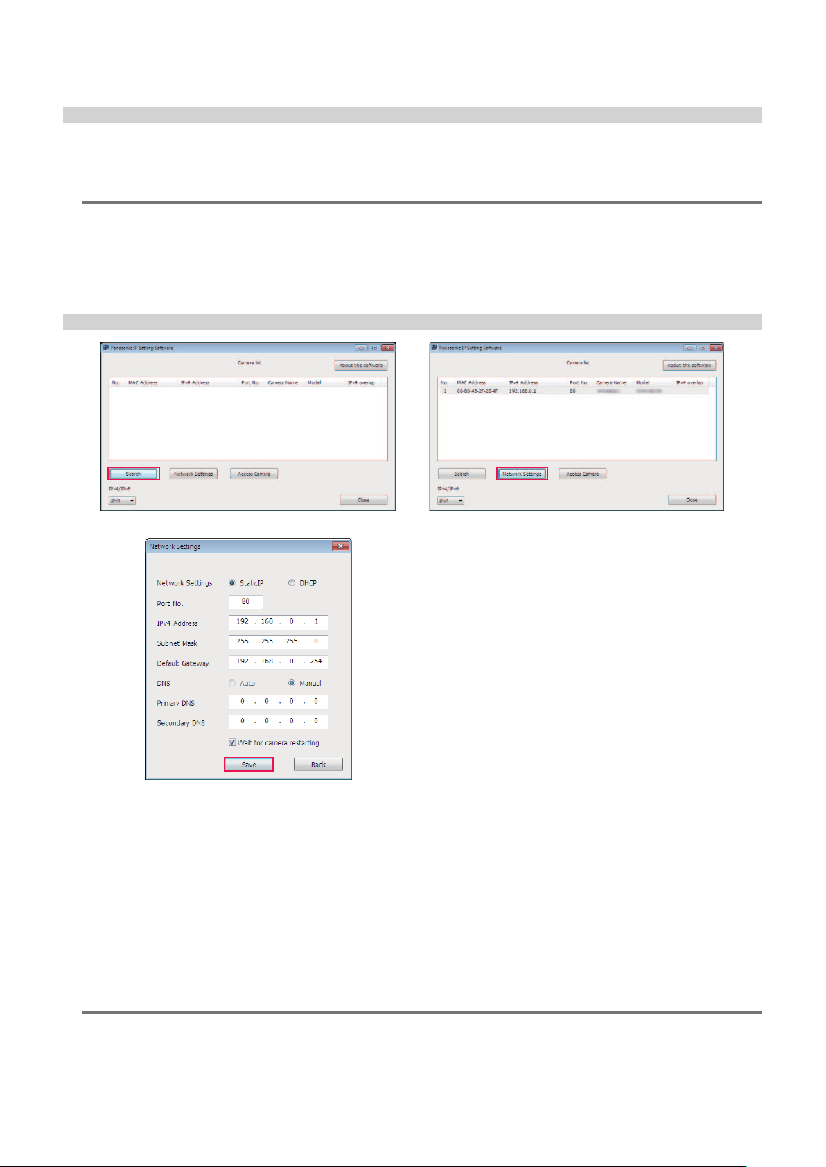
– 180 –
Chapter 9 Network Connection — Network settings
r EASY IP Setup Software (EasyIPSetup.exe)
Congure the network settings of the camera.
Performing settings of the camera using EASY IP Setup Software
The settings for the camera network can be performed using EASY IP Setup Software.
The settings for multiple cameras need to be performed on each camera.
If the settings cannot be specied using EASY IP Setup Software, specify the settings of the camera in the [NETWORK] menu.
@
NOTE
t EASY IP Setup Software can be used only when all of the following conditions are satised.
‑ The [NETWORK] menu → [UTILITY] → [EASY IP SETTING] is set to anything other than [DISABLE]
‑ The [NETWORK] menu → [DEVICE SEL] → [LAN] is set
t The camera will not operate properly after the network settings are specied if the IP address is the same as another device on the same network.
Set a unique IP address for the camera.
t EASY IP Setup Software cannot be used from a different subnet via a router.
t Use Ver.4.25R00 or later for EASY IP Setup Software.
Setting procedure
Fig. 1
Fig. 3
Fig. 2
1
Start EASY IP Setup Software.
2
Click [Search]. (Fig. 1)
3
Click the MAC address/IPv4 address of the camera to set, and then click [Network settings]. (Fig. 2)
f When there are overlapping IP addresses, overlapping camera numbers are displayed in the [Duplicate IPv4 address] eld of the corresponding
camera.
4
Enter each of the network setting items, and then click [Save]. (Fig. 3)
f The connection mode of the camera only supports [Fixed IP]. DHCP and other protocols are not supported. Do not specify these settings.
f It may take approximately two minutes to complete the setting of the camera after clicking [Save].
The settings become invalid if the AC adaptor or LAN cable is disconnected before the settings are complete. Specify the settings again.
@
NOTE
t The IP address assigned to the camera can be checked by clicking [Search] of EASY IP Setup Software when using the DHCP server.
t The camera does not support the IPv6 setting due to EASY IP Setup Software.
t Allow access to all of the ports for UDP when implementing a rewall (including software).
t Some of the items cannot be set on this camera.
t [View Camera Screen] displayed on Fig. 1 and Fig. 2 does not function on this camera.

– 181 –
Chapter 9 Network Connection — Network settings
Conrming the network status
The status of the camera network can be checked using the following operations.
1
Select the [NETWORK] menu → [INFORMATION] → [STATUS].
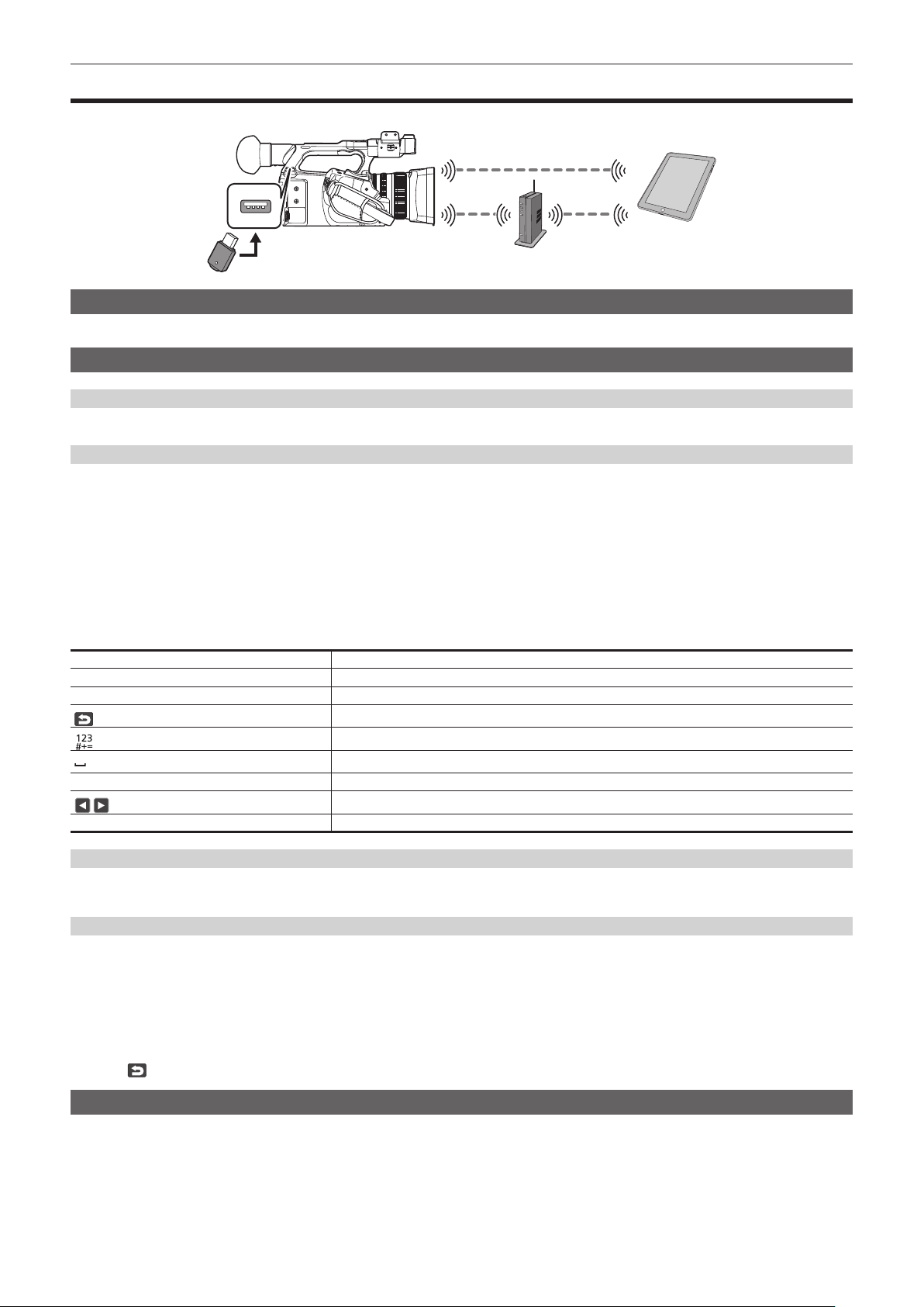
– 182 –
Chapter 9 Network Connection — Connecting to the iPhone/iPad or Android terminal
Connecting to the iPhone/iPad or Android terminal
The camera can be operated from the iPhone/iPad or Android terminal.
Mounting the wireless module
Mount the wireless module (optional) to the camera. (page 176)
Camera settings
Specifying the network settings
Specify the network settings. (page 177)
Setting the user account name and the password
1
Select the [NETWORK] menu → [IP REMOTE] → [USER ACCOUNT].
2
Enter the user account name and select [Enter].
f Enter the user account name with 31 characters or less.
3
Enter the password and select [Enter].
f Enter a password between 8 characters and 15 characters.
r To enter a character
Operation is the same as entering with a keyboard.
Icon Description of operation
[A‑a] Switches between upper case and lower case. (Displayed during the text entry mode)
[@‑#] Switches the type of the symbols. (Displayed during the symbol entry mode)
Returns to the previous screen. Entered character is not reected.
Switches the character to symbol/number.
Enters space (blank).
[BS] Deletes the character. Previous character is deleted when the cursor position is empty.
/
Moves the cursor to right or left.
[Enter] Completes the character entry.
Enabling the IP remote function
1
Select the [NETWORK] menu → [IP REMOTE] → [ENABLE/DISABLE] → [ENABLE].
Checking/deleting user accounts
1
Select the [NETWORK] menu → [IP REMOTE] → [ACCOUNT LIST].
The list of registered user accounts is displayed.
f Proceed to Step
3 to only check user accounts.
2
Select the user account to delete, and then select [SET].
A conrmation message appears.
3
Select
and end the operation.
Preparing the CX ROP app
Install the CX ROP app to the iPhone/iPad or Android terminal.
r For iPhone/iPad
f Download the CX ROP app from the App Store.
r For Android terminal
f Download the CX ROP app from the Google Play Store.

– 183 –
Chapter 9 Network Connection — Connecting to the iPhone/iPad or Android terminal
@
NOTE
t For information such as the supported OS of the CX ROP app, refer to the App Store or the Google Play Store download page.
Connecting to the CX ROP application
Connect to the camera following the CX ROP app guide.
@
NOTE
t The camera cannot connect with the CX ROP app while the menu or thumbnail screen is displayed.
Operation while the CX ROP app is connected
r Operation of the camera that is connected
Following buttons and dial cannot be used.
f <MENU> button
f <THUMBNAIL> button
r Recording and playback operation while connected
f Recording can be operated by either the camera or the CX ROP app.
f Playback operation is not possible.
@
NOTE
t The content set with the remote operation using the CX ROP app is reected to the camera.

– 184 –
Chapter 9 Network Connection — Streaming function
Streaming function
You can perform streaming of audio and video currently shot with the camera over a network (wired LAN/wireless LAN).
Streaming can be performed using the camera, an application software of a device connected via a network, or a server that is capable of receiving
streaming video sent from the camera.
There are two ways to start streaming: streaming from an application software and streaming from the camera. This section describes the camera's
network connection method for each method.
Camera settings
Specifying the network settings
Specify the network settings. (page 177)
Settings for the streaming function
1
Set the [SYSTEM] menu → [FREQUENCY]/[REC FORMAT].
f For details about the setting items, refer to “Settings when using the streaming function” (page 184).
2
Select the [NETWORK] menu → [NETWORK FUNC] → [STREAMING].
Streaming function is enabled.
3
In the [NETWORK] menu → [STREAMING] → [STREAMING FORMAT], set the format when streaming.
f For details about the setting items, refer to “Settings when using the streaming function” (page 184).
@
NOTE
t The streaming function can be used when all of the following conditions are satised.
‑ The [SYSTEM] menu → [FILE FORMAT] is set to anything other than [AVCHD]
‑ The [SYSTEM] menu → [SUPER SLOW] → [OFF] is set
‑ The menu has been set according to “Settings when using the streaming function” (page 184)
(This cannot be used when set to UHD)
‑ VFR and some special recording functions are disabled
r Settings when using the streaming function
[SYSTEM] menu
[NETWORK] menu → [STREAMING]
[FREQUENCY] [REC FORMAT] [STREAMING FORMAT]
[59.94Hz] [1080-59.94p/AVC-I422]
[1080-59.94p/AVC-G25]
[1080-59.94p/AVC-G12]
[1080-59.94p/422LongGOP 100M]
[1080-59.94p/422ALL-I 200M]
[1920×1080-60fps 24M]
[1920×1080-60fps 20M]
[1920×1080-60fps 16M]
[1280×720-60fps 14M]
[1280×720-60fps 8M]
[1280×720-60fps 3M]
[640×360-30fps 4M]
[640×360-30fps 1.5M]
[640×360-30fps 0.7M] (Factory setting)
[320×180-30fps 4M]
[320×180-30fps 1.5M]
[320×180-30fps 0.5M]
[1080-59.94i/AVC-G50]
[1080-59.94i/AVC-G25]
[1080-59.94i/AVC-G12]
[1080-29.97p/422LongGOP 50M]
[1080-29.97p/422ALL-I 100M]
[1080-59.94i/422LongGOP 50M]
[1080-59.94i/422ALL-I 100M]
[1920×1080-30fps 14M]
[1920×1080-30fps 6M]
[1920×1080-30fps 1M]
[1280×720-30fps 8M]
[1280×720-30fps 2M]
[1280×720-30fps 1M]
[640×360-30fps 4M]
[640×360-30fps 1.5M]
[640×360-30fps 0.7M] (Factory setting)
[320×180-30fps 4M]
[320×180-30fps 1.5M]
[320×180-30fps 0.5M]
[1080-23.98p/422LongGOP 50M]
[1080-23.98p/422ALL-I 100M]
[1920×1080-24fps 14M]
[1920×1080-24fps 6M]
[1920×1080-24fps 1M] (Factory setting)
[720-59.94p/AVC-G50]
[720-59.94p/AVC-G25]
[720-59.94p/AVC-G12]
[1280×720-60fps 14M]
[1280×720-60fps 8M]
[1280×720-60fps 3M]
[640×360-30fps 4M]
[640×360-30fps 1.5M]
[640×360-30fps 0.7M] (Factory setting)
[320×180-30fps 4M]
[320×180-30fps 1.5M]
[320×180-30fps 0.5M]

– 185 –
Chapter 9 Network Connection — Streaming function
[SYSTEM] menu
[NETWORK] menu → [STREAMING]
[FREQUENCY] [REC FORMAT] [STREAMING FORMAT]
[50.00Hz] [1080-50.00p/AVC-I422]
[1080-50.00p/AVC-G25]
[1080-50.00p/AVC-G12]
[1080-50.00p/422LongGOP 100M]
[1080-50.00p/422ALL-I 200M]
[1920×1080-50fps 24M]
[1920×1080-50fps 20M]
[1920×1080-50fps 16M]
[1280×720-50fps 14M]
[1280×720-50fps 8M]
[1280×720-50fps 3M]
[640×360-25fps 4M]
[640×360-25fps 1.5M]
[640×360-25fps 0.7M] (Factory setting)
[320×180-25fps 4M]
[320×180-25fps 1.5M]
[320×180-25fps 0.5M]
[1080-50.00i/AVC-G50]
[1080-50.00i/AVC-G25]
[1080-50.00i/AVC-G12]
[1080-25.00p/422LongGOP 50M]
[1080-25.00p/422ALL-I 100M]
[1080-50.00i/422LongGOP 50M]
[1080-50.00i/422ALL-I 100M]
[1920×1080-25fps 14M]
[1920×1080-25fps 6M]
[1920×1080-25fps 1M]
[1280×720-25fps 8M]
[1280×720-25fps 2M]
[1280×720-25fps 1M]
[640×360-25fps 4M]
[640×360-25fps 1.5M]
[640×360-25fps 0.7M] (Factory setting)
[320×180-25fps 4M]
[320×180-25fps 1.5M]
[320×180-25fps 0.5M]
[720-50.00p/AVC-G50]
[720-50.00p/AVC-G25]
[720-50.00p/AVC-G12]
[1280×720-50fps 14M]
[1280×720-50fps 8M]
[1280×720-50fps 3M]
[640×360-25fps 4M]
[640×360-25fps 1.5M]
[640×360-25fps 0.7M] (Factory setting)
[320×180-25fps 4M]
[320×180-25fps 1.5M]
[320×180-25fps 0.5M]
Starting streaming with an operation from the application software
1
Select the [NETWORK] menu → [STREAMING] → [START TRIGGER] → [RECEIVER].
2
Specify the IP address and the path of the camera with the application software as follows, and start streaming.
rtsp://(IP address)/stream
@
NOTE
t Perform an operation from the application software to stop streaming.
t Only RTSP is available when starting streaming with an operation from application software.
t For details about the operations to start streaming from the application software, please see the manual for each application software.
t Streaming stops when performing operations such as displaying the thumbnail screen or playing back clips on the camera.
t Streaming may stop when the date/time is set while streaming.
Streaming with multicast
One streaming can be distributed to multiple receivers via supported router, etc., when the multicast function is used.
1
Select the [NETWORK] menu → [STREAMING] → [START TRIGGER] → [RECEIVER(MULTICAST)].
2
Select the [NETWORK] menu → [STREAMING], and specify [MULTICAST ADDRESS] and [MULTICAST PORT].
f Set [MULTICAST ADDRESS] within following range.
IPv4: 224.0.1.0 to 239.255.255.254
IPv6: Multicast address starting with FF
f Set [MULTICAST PORT] within the range of 1024 to 50000.
3
Specify the address of the camera and start streaming with the application software.
@
NOTE
t Multicast cannot start streaming with the operation on the camera.
t Disable the LAN card not to be used when receiving the multicast image to be displayed on a computer with multiple LAN cards installed.
Starting streaming with an operation on the camera
1
Select the [NETWORK] menu → [STREAMING] → [START TRIGGER] → [CAMERA].
2
Set the destination.
For details of setting the destination, refer to “Setting the destination for streaming in the menu of the camera” (page 186) or “Referring to the
memory card for the destination of streaming” (page 186).

– 186 –
Chapter 9 Network Connection — Streaming function
3
Select the [NETWORK] menu → [STREAMING] → [START] → [ON].
If the camera is connected to the transmission destination through a network, the camera starts the transmission of streaming video.
@
NOTE
t [START] menu cannot be selected when the streaming cannot be started due to reasons such as the network is not connected, etc.
t Starting/stopping of the streaming from the camera can be assigned to the USER button. (page 52)
Streaming cannot be started by pressing the USER button or touching the USER button icon when the menu or the thumbnail screen is displayed.
t Only RTMP and RTMPS are available when starting streaming with an operation from the camera. In such case, IPv6 cannot be used.
t For settings such as URL, refer to the manual for each streaming service.
t Streaming may not be possible depending on the operating condition of the streaming service.
t Streaming stops when performing operations such as displaying the thumbnail screen or playing back clips on the camera.
t Streaming may stop when the date/time is set while streaming.
Setting the destination for streaming in the menu of the camera
1
Select the [NETWORK] menu → [STREAMING] → [CONNECTION INFO.] → [MEMORY].
2
Enter the destination URL in the [NETWORK] menu → [STREAMING] → [RECEIVER URL].
f Enter the destination URL in following format.
‑ rtmp://(server URL):(port number)/(path)/(stream key)
‑ rtmps://(server URL):(port number)/(path)/(stream key)
@
NOTE
t In general, a parameter for the stream key is required with RTMP, but the stream key may be contained as a part of the path depending on the service.
For details, refer to the manual for each streaming service.
t Setting of [RECEIVER URL] is not possible when [DATA TYPE] is set to [P2CAST]. Set this after performing the operation for [CLEAR (MEMORY)]
once.
Referring to the memory card for the destination of streaming
1
Insert the memory card with the destination information saved into card slot 1.
2
Select the [NETWORK] menu → [STREAMING] → [CONNECTION INFO.] → [SD CARD].
Management of destination information
Destination information can be saved and loaded between the menu of the camera and the memory card.
r Saving the destination information on the memory card
1
Insert a memory card formatted with the camera into card slot 1.
2
Select the [NETWORK] menu → [STREAMING] → [SAVE (SD CARD)].
3
Select [YES] when the confirmation message is displayed.
@
NOTE
t The name of the le in the memory card to save the destination information cannot be changed.
t The le with the destination information saved on the memory card is encrypted.
t Save is not possible when [DATA TYPE] is set to [P2CAST].
t Save is not possible when the starting character string of the [RECEIVER URL] (“rtmp://”, etc.) is not set correctly.
r Loading destination information from the memory card
1
Insert the memory card with the destination information saved into card slot 1.
2
Select the [NETWORK] menu → [STREAMING] → [LOAD (SD CARD)].
3
Select [YES] when the confirmation message is displayed.
@
NOTE
t The name of the le to load destination information saved on the memory card cannot be selected.
t The setting information that can be loaded (referenced) by the camera is as follows.
‑ Information saved with the camera
‑ Setting le created with the P2 Network Setting software (page 187)
‑ Prole downloaded with P2 Cast (page 190)
Clearing the destination information
1
Select the [NETWORK] menu → [STREAMING] → [CLEAR (MEMORY)].
f The setting information for P2 Cast is also cleared.
f The destination URL information set in P2 Cast is also cleared. (page 190)
f The setting related to multicast is not cleared.
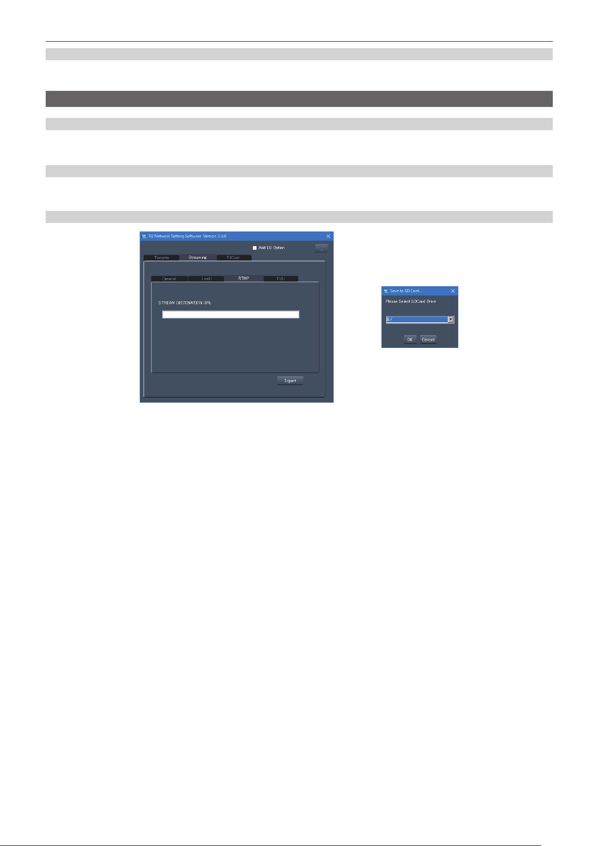
– 187 –
Chapter 9 Network Connection — Streaming function
Stopping streaming of video
1
Select the [NETWORK] menu → [STREAMING] → [START] → [OFF].
Entering the setting using the setting tool
Installing software
Download and expand the P2 Network Setting software for Windows from the following website.
https://pro-av.panasonic.net/
Creating the SDXC memory card for setting using the P2 Network Setting software
The SDXC memory card created with this software can be used as the reference destination when loading into the camera menu or when the
[NETWORK] menu → [STREAMING] → [CONNECTION INFO.] → [SD CARD] is selected.
Setting procedure
Fig. 1 Fig. 2
1
Start the P2 Network Setting software. (Fig. 1)
2
Select the Streaming tab → RTMP tab.
3
Enter the destination URL in STREAM DESTINATION URL.
4
Click Export and select the destination in the drive selection dialog (Fig. 2), and then click OK.
f This cannot be saved to anything other than a removable drive.

– 188 –
Chapter 9 Network Connection — NDI|HX function
NDI|HX function
The camera can be connected to a NDI|HX compatible switches made by NewTek.
@
NOTE
t Purchasing of the activation key is required to use the NDI|HX function. For details, refer to the website of NewTek.
t For details of each operation, refer to the operating instruction of the NDI|HX compatible switcher.
t The following functions cannot be used when the NDI|HX function is enabled. Some of the menu items related to those functions cannot be selected
as well.
‑ Recording function
‑ Functions of the playback system including the thumbnail display
‑ Wireless LAN
Camera settings
Specifying the network settings
Sets the wired LAN setting. (page 178)
Setting for the NDI|HX function
1
Set the [SYSTEM] menu → [FREQUENCY]/[REC FORMAT].
f For details about the setting items, refer to “Settings when using the NDI|HX function” (page 188).
2
Select the [NETWORK] menu → [NETWORK FUNC] → [NDI|HX].
The NDI|HX function is selected. The camera will automatically restart.
3
Set the streaming format with the [NETWORK] menu → [NDI|HX] → [STREAMING FORMAT].
This cannot be used when set to UHD.
@
NOTE
t The NDI|HX function can be used when all of the following conditions are satised.
‑ The [SYSTEM] menu → [FILE FORMAT] is set to anything other than [AVCHD]
‑ The [SYSTEM] menu → [SUPER SLOW] → [OFF] is set
‑ The menu has been set according to “Settings when using the NDI|HX function” (page 188)
‑ VFR and some special recording functions are disabled
t The [NETWORK] menu → [UTILITY] → [EASY IP SETTING] is switched to [UNLIMITED] when the NDI|HX function is enabled.
r Settings when using the NDI|HX function
[SYSTEM] menu
[NETWORK] menu → [NDI|HX]
[FREQUENCY] [REC FORMAT] [STREAMING FORMAT]
[59.94Hz] [1080-59.94p/AVC-I422]
[1080-59.94p/AVC-G25]
[1080-59.94p/AVC-G12]
[1080-59.94p/422LongGOP 100M]
[1080-59.94p/422ALL-I 200M]
[1920×1080-60fps 24M]
[1920×1080-60fps 16M]
[1920×1080-60fps 10M] (Factory setting)
[1920×1080-60fps 8M]
[1280×720-60fps 14M]
[1280×720-60fps 10M]
[1280×720-60fps 6M]
[1080-59.94i/AVC-G50]
[1080-59.94i/AVC-G25]
[1080-59.94i/AVC-G12]
[1080-29.97p/422LongGOP 50M]
[1080-29.97p/422ALL-I 100M]
[1080-59.94i/422LongGOP 50M]
[1080-59.94i/422ALL-I 100M]
[1920×1080-30fps 14M]
[1920×1080-30fps 10M] (Factory setting)
[1920×1080-30fps 6M]
[1280×720-30fps 8M]
[1280×720-30fps 4M]
[1280×720-30fps 2M]
[720-59.94p/AVC-G50]
[720-59.94p/AVC-G25]
[720-59.94p/AVC-G12]
[1280×720-60fps 14M]
[1280×720-60fps 10M] (Factory setting)
[1280×720-60fps 6M]
[50.00Hz] [1080-50.00p/AVC-I422]
[1080-50.00p/AVC-G25]
[1080-50.00p/AVC-G12]
[1080-50.00p/422LongGOP 100M]
[1080-50.00p/422ALL-I 200M]
[1920×1080-50fps 24M]
[1920×1080-50fps 16M]
[1920×1080-50fps 10M] (Factory setting)
[1920×1080-50fps 8M]
[1280×720-50fps 14M]
[1280×720-50fps 10M]
[1280×720-50fps 6M]
[1080-50.00i/AVC-G50]
[1080-50.00i/AVC-G25]
[1080-50.00i/AVC-G12]
[1080-25.00p/422LongGOP 50M]
[1080-25.00p/422ALL-I 100M]
[1080-50.00i/422LongGOP 50M]
[1080-50.00i/422ALL-I 100M]
[1920×1080-25fps 14M]
[1920×1080-25fps 10M] (Factory setting)
[1920×1080-25fps 6M]
[1280×720-25fps 8M]
[1280×720-25fps 4M]
[1280×720-25fps 2M]
[720-50.00p/AVC-G50]
[720-50.00p/AVC-G25]
[720-50.00p/AVC-G12]
[1280×720-50fps 14M]
[1280×720-50fps 10M] (Factory setting)
[1280×720-50fps 6M]

– 189 –
Chapter 9 Network Connection — NDI|HX function
Enabling the NDI|HX function
Perform the setting for the NDI|HX function, and then enable the NDI|HX function referring to the information in the NewTek website, etc. [NDI|HX] is
displayed in the [NETWORK] menu → [NDI|HX] → [ACTIVATION] when the NDI|HX function is enabled.
@
NOTE
t The NDI|HX function will remain enabled once it has been set, unless the activation information saved on the camera is deleted.
t To enable the NDI|HX function of the camera using the tool from NewTek, it is necessary to select [NDI|HX] in the [NETWORK] menu → [NETWORK
FUNC].
Streaming with multicast
One streaming can be distributed to multiple NDI|HX compatible switchers via supported router, etc., when the multicast function is used.
1
Select the [NETWORK] menu → [NDI|HX] → [MULTICAST] → [ENABLE].
2
Select the [NETWORK] menu → [NDI|HX], and specify [MULTICAST ADDRESS] and [MULTICAST PORT].
f Set [MULTICAST ADDRESS] within following range.
IPv4: 224.0.1.0 to 239.255.255.254
IPv6: Multicast address starting with FF
f Set [MULTICAST PORT] within the range of 1024 to 50000.
@
NOTE
t One that has added + 1 to the end of the specied multicast address is also used for NDI|HX.
t Disable the LAN card not to be used when receiving the multicast video to be displayed on a computer with multiple LAN cards installed.
Using the NDI|HX function
Control the camera by operating the NDI|HX compatible switcher.
@
NOTE
t Streaming may stop when the date/time is set while streaming.
Disabling the NDI|HX function
1
Select the [NETWORK] menu → [NDI|HX] → [CLEAR ACTIVATION].
The activation information saved to the camera is deleted.
After the activation information is deleted, the NDI|HX function cannot be used until the NDI|HX function is enabled again.

– 190 –
Chapter 9 Network Connection — Using P2 Cast
Using P2 Cast
r P2 Cast
By using P2 Cast, the status of the camera operating in the remote area can be conrmed and the RTMP streaming can be remotely operated.
For details, refer to the following website.
https://pro-av.panasonic.net/
@
NOTE
t A contract is required to use P2 Cast. For details, consult your dealer.
t Some of the functions of P2 Cast cannot be used with this camera.
t There are some functions that cannot be used depending on the P2 Cast server being used.
Procedure for using
For details, refer to the P2 Cast documents.
1
Login to P2 Cast, and download the profile.
2
Decompress the downloaded file.
3
Save the decompressed PRIVATE folder in the root directory of the SDXC memory card.
4
Perform the setting of the camera as follows.
f Select the [NETWORK] menu → [STREAMING] → [START TRIGGER] → [CAMERA].
f Insert a SDXC memory card into the card slot 1, and load the prole into the camera with one of the following.
1) Select the [NETWORK] menu → [STREAMING] → [CONNECTION INFO.] → [MEMORY], and load the content of SD with the [NETWORK]
menu → [STREAMING] → [LOAD (SD CARD)].
2) Select the [NETWORK] menu → [STREAMING] → [CONNECTION INFO.] → [SD CARD].
5
Perform each operation with P2 Cast.
Streaming from P2 Cast
f Remote operation of the RTMP streaming is not possible when the menu or the thumbnail screen is displayed on the camera.
f Once the operation to start streaming from P2 Cast or setting of the destination URL is performed, the destination URL is recorded inside the camera.
Streaming to the same destination can be performed with the operation from the camera after that. (page 185)
f The recorded destination URL cannot be viewed on the camera.
f The recorded destination URL information is also cleared when the destination information is cleared.
For details on clearing the destination information, refer to “Clearing the destination information” (page 186).

Maintenance of the camera or frequently asked questions are described.
Chapter 10 Notes

– 192 –
Chapter 10 Notes — Frequently asked questions
Frequently asked questions
Power supply
r What is the power supply voltage supported by the supplied AC adaptor?
f AC 100 V-240 V
r Can the supplied AC adaptor used while the battery is mounted?
f It can be used. Supplying of the power is automatically switched to the AC adaptor side when the power is set to < j > (ON) and the AC adaptor is
connected while the battery is mounted.
The power status display in the LCD monitor will change from the
mark to the mark.
r The camera cannot be operated even when the power is set to < j > (ON).
f Remove the power supply (the battery or the AC adaptor), and connect it again after approximately one minute.
Battery
r The battery gets exhausted quickly, so is there any way to improve?
f Charge the battery sufciently.
f The operating time becomes shorter in low temperature.
f If the time is short after sufcient charging, the battery life has expired.
r Can the battery that was used in the previous models used?
f VW-VBD58 (optional) can be used.
It is recommended to use the following Panasonic genuine batteries.
-AG-VBR59 (supplied/optional, 7.28 V, 5900 mAh)
-AG-VBR89 (optional, 7.28 V, 8850 mAh)
-AG-VBR118 (optional, 7.28 V, 11800 mAh)
r Can the supplied battery be charged with the battery charger AG-B23 (DE-A88) (optional)?
f It can perform normal charging. It cannot perform quick charging.
Battery charger
r Can the previous battery charged with the supplied charger?
f It can perform normal charging.
f To perform quick charging, use the quick charging compatible battery. The camera is compatible to following quick charging compatible batteries.
-AG-VBR59 (supplied/optional, 7.28 V, 5900 mAh)
-AG-VBR89 (optional, 7.28 V, 8850 mAh)
-AG-VBR118 (optional, 7.28 V, 11800 mAh)
Memory card
r Operation is not accepted even when a memory card is inserted into the card slot.
f The memory card to use with the camera should always be formatted on the camera.
The memory card formatted on a computer cannot be used in the camera.
Shooting
r The focus is not adjusted automatically.
f Is the manual focus mode set? Set the auto focus mode to adjust the focus automatically.
f Are you shooting in conditions which focusing is difcult with the auto focus mode? Auto focus has trouble focusing under certain conditions. In this
case, the manual focus mode can be used to focus the camera.
Under following conditions, focus may not be adjusted properly:
-Shooting subjects that is in long and short distances at the same time
-Shooting a subject through a dirty glass
-Shooting in a dark place
-With a glittering object nearby
-Shooting a fast-moving subject
-Shooting a low contrast subject
r The shooting stops by itself, and cannot shoot.
f Use the SDXC memory card, the microP2 card B series or the 64 GB microP2 card A series when the recording format is set to MOV format. The
camera cannot record data in MOV format to the SDHC memory card or the 32 GB microP2 card A series.
f Use the memory card with the required Speed Class in accordance with the recording bit rate. (page 41)
r Audio cannot be recorded.
f Audio cannot be recorded in the following cases.
-When the variable frame rate recording function is enabled, and the frame rate is set different from the system frequency

– 193 –
Chapter 10 Notes — Frequently asked questions
-When the super slow recording function is enabled
-When the interval recording function is enabled
f
is displayed in the camera image screen when audio cannot be recorded.
Playback
r The clip cannot be played back.
f The clip displaying
in the thumbnail screen cannot be played back.
is displayed on following clips.
-A clip shot with other device, a clip edited by an editing software
-Corrupted clip
f
is displayed on the clip in the thumbnail screen for the clips with different system frequency. Change the system frequency.
f The clip with different recording le format (P2/MOV/AVCHD) is not displayed in the thumbnail screen. Change the recording le format.
r The clip cannot be erased.
f Cancel the protect on the clip.
f The clip displaying
in the thumbnail screen may not be able to erase.
Format the memory card if the clip is unnecessary.
All the data recorded on the memory will be erased when formatted. Save the necessary data into a computer, etc.
r Can the contents shot with AG-DVX200 or AG-UX180 be played back?
f The contents recorded in MOV format/MP4 format cannot be played back.
f The contents recorded in AVCHD format can be played back. Contents recorded in the format that cannot be recorded with the camera cannot be
played back.
r Hot swap playback cannot be performed.
f This camera does not support hot swap playback.
Others
r The memory card is not recognized.
f Is the memory card formatted correctly? Format the card with the camera.
r The camera clatters when tilted forward/backward.
f When the power switch is set to < h > (standby), the camera may clatter due to the camera part mechanism. This is not a malfunction.
r A short click sound occurs when the power is turned on.
f This is an initial operation of the startup of the lens of the camera. This is due to the camera mechanism and is not a malfunction.
r Which lens lter can be attached?
f 67 mm diameter lter can be attached.
r Can the wired remote control used with AG-DVX200 series be used?
f The controlling format is different, so it cannot be used.
– 194 –
Chapter 10 Notes — Warning system
Warning system
When an error is detected right after the camera is turned on or during the operation, the occurrence of the error is notied in the camera image screen
of the LCD monitor or by the tally lamp. Deal with the error by following the indications.
Cases indicated by error messages
System error
Screen display
Description Behavior and cause
Camera image screen
[SYSTEM ERROR] An error in the standard signal or communication error has
occurred.
All the tally lamps and the card access lamps (orange) will
ash four times a second, and an alarm is sounded.
f Set the power to < h > (standby).
Warning
Screen display
Description Behavior and cause
Camera image screen
[LOW BATTERY] Remaining battery level is insufcient. All the tally lamps and the card access lamps (orange) will
ash four times a second, and an alarm is sounded.
The power status display becomes
, and it will ash
once every second in red.
f The power is turned off in approximately ve seconds.
f Replace with a fully charged battery, or connect the AC
adaptor.
[HIGH TEMPERATURE] Displayed when the internal temperature of the camera has
risen above assumed.
All the tally lamps and the card access lamps (orange) will
ash four times a second, and an alarm is sounded.
f The power is turned off in approximately ve seconds.
f Turn on the power again and check recording and
playback operations. If the problem persists, consult the
dealer.
[REC WARNING] An error of the recording data has occurred during
recording, and the recording has stopped.
All the tally lamps and the card access lamps (orange) will
ash four times a second, and an alarm is sounded.
f Recording is stopped.
It has tried to record exceeding the maximum number of
clips during recording.
All the tally lamps and the card access lamps (orange) will
ash four times a second, and an alarm is sounded.
f Recording is stopped.
f [REC WARNING] [<OVER MAX NUM. OF CLIPS>] is
displayed in the warning display eld of the STATUS
screen for the mode check.
f Replace the memory card or delete unnecessary clips.
[CARD ERROR <SLOT 1>]/[CARD
ERROR <SLOT 2>]
A data error caused by the memory card has occurred
during recording or playback.
f When it was recording
All the tally lamps and the card access lamps (orange)
will ash four times a second, and an alarm is sounded.
Recording is stopped.
The memory card where the error has occurred is write
protected after recording stops. Replace the memory
card in the card slot where the error has occurred.
f When it was playing back
Playback is stopped.
[END]
(Memory card status display)
The remaining recording capacity of the memory card has
exhausted during recording.
All the tally lamps and the card access lamps (orange) will
ash four times a second, and an alarm is sounded.
f Recording is stopped.
f Replace the memory card or delete unnecessary clips.
(Once every second, ash in red)
Battery is almost consumed. All the tally lamps will ash once every second.
f The current operation will continue.
f Replace with a fully charged battery, or connect the AC
adaptor.
Remaining recording capacity display
of the memory card
(Flashes once every second during
recording)
The remaining recording capacity of the memory card is
getting low.
f Recording will continue.
f Replace the memory card as necessary.

– 195 –
Chapter 10 Notes — Warning system
Alert
Screen display
Description Behavior and cause
Camera image screen
[SIMUL REC WARNING <SLOT 1>]/
[SIMUL REC WARNING <SLOT 2>]
An error has occurred in one of the memory cards during
simultaneous recording.
A message is displayed for approximately ve seconds.
f Recording to the other memory card will continue.
[SIMUL REC WARNING <SLOT 1>]/
[SIMUL REC WARNING <SLOT 2>]
Recording has been attempted while the number of clips
has exceeded the limit on one of the memory cards during
simultaneous recording.
A message is displayed for approximately ve seconds.
f Recording to the other memory card will continue.
f [SIMUL REC WARNING <SLOT 1>] [<OVER MAX
NUM. OF CLIPS>]/[SIMUL REC WARNING <SLOT 2>]
[<OVER MAX NUM. OF CLIPS>] is displayed in the
warning display eld of the STATUS screen for the mode
check.
f Replace the memory card or delete unnecessary clips.
[BACKGROUND REC WARNING
<SLOT 1>]/[BACKGROUND REC
WARNING <SLOT 2>]
An error has occurred in one of the memory cards during
background recording.
A message is displayed for approximately ve seconds.
f Recording to the other memory card will continue.
[BACKGROUND REC WARNING
<SLOT 1>]/[BACKGROUND REC
WARNING <SLOT 2>]
Recording has been attempted while the number of clips
has exceeded the limit on one of the memory cards during
background recording.
A message is displayed for approximately ve seconds.
f Recording to the other memory card will continue.
f [BACKGROUND REC WARNING <SLOT 1>] [<OVER
MAX NUM. OF CLIPS>]/[BACKGROUND REC
WARNING <SLOT 2>] [<OVER MAX NUM. OF CLIPS>]
is displayed in the warning display eld of the STATUS
screen for the mode check.
f Replace the memory card or delete unnecessary clips.
[FAN STOPPED] The fan has stopped. A message is displayed.
f The current operation will continue.
f Stop the use immediately when the fan has stopped, and
consult the dealer.
f If the fan has stopped, temperature of the camera will
rise. Therefore, do not use the camera for a long period
of time.
[REINSERT OR CHECK CARD
<SLOT 1>]/[REINSERT OR CHECK
CARD <SLOT 2>]
The memory card cannot be recognized properly because
a recording medium which is not supported has been
inserted or there is dirt on the terminal of the memory card.
A message is displayed for approximately ve seconds.
f Check the memory card that is inserted.
f Insert the memory card again if displayed when inserting
a memory card.
[FORMAT ERROR CARD <SLOT 1>]/
[FORMAT ERROR CARD <SLOT 2>]
A memory card with management information out of
specications has been inserted.
(Include when the system frequency (59.94 Hz system or
50.00 Hz system) for the AVCHD format of the memory
card is different from the setting in the [SYSTEM] menu →
[FREQUENCY])
A message is displayed for approximately ve seconds.
f Insert a memory card that can record.
f The system frequency information for the AVCHD format
is conrmed at the time of formatting or at the rst
recording.
[NOT SDXC CARD <SLOT 1>]/[NOT
SDXC CARD <SLOT 2>]
A SDHC memory card that cannot record the MOV format
data or a 32 GB microP2 card is inserted when [FILE
FORMAT] is set to MOV format.
A message is displayed for approximately ve seconds.
f Insert a SDXC memory card or 64 GB microP2 card.
[INCOMPATIBLE CARD <SLOT 1>]/
[INCOMPATIBLE CARD <SLOT 2>]
A memory card that may not be able to record due to slow
writing speed has been inserted.
A message is displayed for approximately ve seconds.
f The current operation will continue.
f Use a memory card with sufcient writing speed.
[DIR NG CARD <SLOT 1>]/[DIR NG
CARD <SLOT 2>]
A microP2 card with inappropriate directory placement is
inserted when [FILE FORMAT] is set to P2 format
A message is displayed for approximately ve seconds.
f The current operation will continue.
f Take a backup of the card immediately, and use again
after formatting.
[RUN DOWN CARD <SLOT 1>]/[RUN
DOWN CARD <SLOT 2>]
A microP2 card exceeding the specied number of
overwrites is inserted.
A message is displayed for approximately ve seconds.
f The current operation will continue.
f Replacement of the microP2 card is recommended.
[SD CARD <SLOT 1>]/[SD CARD
<SLOT 2>]
SDHC/SDXC memory card is inserted when [FILE
FORMAT] is set to P2 format.
A message is displayed for approximately ve seconds.
f The current operation will continue.
f Recording to a microP2 card is recommended.
[BACKUP BATT EMPTY] Voltage lowering of the backup battery for internal clock
was detected when the power is set to < j > (ON).
A message is displayed for approximately ve seconds.
f The current operation will continue.
f Set the date/time again after charging the built-in battery.

– 196 –
Chapter 10 Notes — Warning system
Message
Screen display
Description Behavior and cause
Camera image screen
[CANNOT PLAY.] This is a clip that cannot be played back.
(When it cannot be played back due to difference of the
system frequency, etc.)
An error has occurred during playback, and the playback
has stopped.
A message is displayed.
f Conrm if the system frequency of the clip is the same as
the system frequency of the camera.
f Check the clip.
[CANNOT DELETE.] This is a clip that cannot be deleted. A message is displayed.
f Match the device and content versions.
[CANNOT RECORD. THE NUMBER
OF CLIPS HAS EXCEEDED THE
MAXIMUM LIMIT.]
The number of clips that can be recorded has reached the
maximum.
A message is displayed.
f Replace the memory card or delete unnecessary clips.
[CARD ERROR. PLEASE
REFORMAT.]
Formatting of the memory card has failed. A message is displayed.
f Format it again.
[COPY IMPOSSIBLE. TOO LARGE
CLIP CONTAINED.]
The le for P2 clip exceeding 4 GB cannot be copied to a
memory card with 32 GB or less.
A message is displayed.
f Copy to a memory card with the capacity exceeding
32 GB.
[CANNOT COPY TO SAME CARD.] The clip recorded over multiple memory cards cannot be
copied to a same card.
A message is displayed.
f Copy to a card not containing a clip that is recorded over
multiple memory cards.
[Repair failed.] Repairing the clip where an error occurred has failed
because the power was disconnected or the memory card
was removed during recording.
Restoring of the management information has failed.
A message is displayed.
f Check the memory card.
[UNABLE TO FORMAT.] This memory card cannot be formatted. A message is displayed.
f Check the memory card.
[CANNOT REPAIR CONTROL
INFORMATION DUE TO LOW
BATTERY POWER.]
Management information cannot be restored due to
insufcient remaining battery level.
A message is displayed.
f Replace with a fully charged battery, or connect the AC
adaptor.
[CANNOT PROTECT.] This is a clip that cannot be protected. A message is displayed.
f Match the device and content versions.
[THE CLIP IS PROTECTED. PLEASE
CANCEL PROTECTION.]
The clip is protected so it cannot be deleted. A message is displayed.
f Cancel the protect on the clip.
[CANNOT DELETE UNTIL TOP
MENU IS DELETED. DELETE TOP
MENU? (RECORDED DATA WILL
NOT BE DELETED)]
The camera is trying to delete a clip on the memory card
where the top menu has been created.
A message is displayed.
f Delete the top menu.
[CANNOT RECORD UNTIL TOP
MENU IS DELETED. DELETE TOP
MENU? (RECORDED DATA WILL
NOT BE DELETED)]
The memory card where the top menu was created has
been inserted.
A message is displayed.
f Delete the top menu.
[THUMBNAIL DATA ERROR IS
DETECTED.]
An error occurred in the thumbnail information of the
memory card.
A message is displayed.
f Restoring of the management information is performed
automatically after this.
[CANNOT RECORD ‑
INCOMPATIBLE CONTROL DATA.]
The version of the management information on the
memory card is not supported.
A message is displayed.
f Match the device and content versions.
[CANNOT SET.] This cannot be set. A message is displayed.
f Perform the setting after making it possible to set.
[THIS CLIP CANNOT BE COPIED.] The clip cannot be copied. A message is displayed.
f Copy the clips other than the corresponding clip.
[CONTROL DATA ERROR HAS BEEN
DETECTED. (SD CARD)]
An error occurred in the management information of the
memory card.
A message is displayed.
f Restoring of the management information is performed
automatically after this.
[COPY FAILED. PLEASE CHECK
THE CARD.]
The clip has failed to copy due to an error in the memory
card.
A message is displayed.
f Check the memory card.
[COPY TERMINATION IN
PROGRESS DUE TO INSUFFICIENT
BATTERY POWER. DO NOT SWITCH
OFF.]
Remaining battery level became low while copying the
clip.
A message is displayed.
f The copy is canceled.
f Replace with a fully charged battery, or connect the AC
adaptor.
[COPY TERMINATED DUE TO
INSUFFICIENT BATTERY POWER.]
Copying of a clip is canceled due to insufcient remaining
battery level.
A message is displayed.
f Replace with a fully charged battery, or connect the AC
adaptor.
[CANNOT COPY - THE NUMBER OF
CLIPS HAS REACHED MAXIMUM.]
The number of clips that can be copied has reached the
maximum.
A message is displayed.
f Replace the memory card in the copy destination or
delete unnecessary clips.
[LOW BATTERY. PLEASE CONNECT
AC ADAPTOR OR CHANGE
BATTERY.]
It is trying to copy a clip or update the camera rmware
while the remaining battery level is insufcient.
A message is displayed.
f Replace with a fully charged battery, or connect the AC
adaptor.
[CANNOT PLAY THIS CLIP ON THIS
MODEL.]
This is a clip that cannot be played back with the camera. A message is displayed.
f Playback on a device that can playback.
[Cannot copy: contains recordings
from other devices.]
The clip recorded in other device cannot be copied. A message is displayed.
f Copy the clips other than the corresponding clip.

– 197 –
Chapter 10 Notes — Warning system
Screen display
Description Behavior and cause
Camera image screen
[ERROR HAS OCCURRED. TO
REPAIR THE CONTROL DATA,
PLEASE CONNECT AC ADAPTOR
OR CHANGE BATTERY.]
The remaining battery level was low when the restoring of
the management information is started.
A message is displayed.
f Replace with a fully charged battery, or connect the AC
adaptor.
[INVALID] Operation is disabled. A message is displayed.
f Operate after the the operation becomes enabled.
[Cannot record - Playlist capacity is
full.]
The camera tried to record on a memory card where
the number of playlists for recording has reached the
maximum.
A message is displayed.
f Replace the memory card or delete unnecessary clips.
[Cannot copy - Playlist capacity is full.] The camera tried to copy to a memory card where
the number of playlists for recording has reached the
maximum.
A message is displayed.
f Replace the memory card or delete unnecessary clips.
[Exceeds capacity. Please reselect.] The remaining recording capacity of the memory card for
the copy destination is insufcient.
A message is displayed.
f Select the clip to copy again, or secure enough space in
the remaining recording capacity on the memory card for
the copy destination.
[Check the destination media.] An error has occurred on the memory card for the copy
destination while copying.
A message is displayed.
f Conrm the memory card for the copy destination.
[SCENE FILE LOAD FAILED] Loading of the scene le has failed. A message is displayed.
f Check the memory card.
[SCENE FILE WRITE FAILED] Writing of the scene le has failed. A message is displayed.
f Check the memory card.
[DISCONNECT USB CABLE.] Due to an OS non-compatible error, ve minutes has
elapsed until the service mode connection is established.
A message is displayed.
f Conrm if the OS in use is supported by the camera.
[CARD LOCKED.] The camera tried to protect or delete a clip on a memory
card that has been locked.
The camera tried to copy a clip to the memory card that
has been locked.
A message is displayed.
f Unlock the memory card.
[CANNOT SELECT MORE CLIPS.] It has tried to select more than 99 clips. A message is displayed.
f Execute the process such as copying by every 99 clips.
[SELECT THE CLIP TO BE
DELETED.]
It has tried to delete a clip without choosing any. A message is displayed.
f Select a clip to be deleted.
[SELECT THE CLIPS TO COPY.] It has tried to copy a clip without choosing any. A message is displayed.
f Select a clip to be copied.
[Insert a card in slot 1.] Copying was tried to be executed without inserting a
memory card into card slot 1.
A message is displayed.
f Insert a memory card into card slot 1.
[Insert a card in slot 2.] Copying was tried to be executed without inserting a
memory card into card slot 2.
A message is displayed.
f Insert a memory card into card slot 2.
[REINSERT OR CHECK CARD
<SLOT 1>]/[REINSERT OR CHECK
CARD <SLOT 2>]
It has tried to copy to an error card. A message is displayed.
f Check the memory card.
[CANNOT COPY.] Copying was attempted while the system frequency
(59.94 Hz and 50.00 Hz) of the memory card to copy from
and the memory card to copy to are different for content
recorded in AVCHD format.
A message is displayed.
f Set the same system frequency (59.94 Hz system or
50.00 Hz system) for the content of the memory card to
copy from and the memory card to copy to.
f The system frequency information for the AVCHD format
is conrmed at the time of formatting or at the rst
recording.
[CANNOT RECORD.] Cannot be recorded. A message is displayed.
f Perform recording after making it possible.
[REC PAUSE INVALID] The camera tried to stop the next recording before the
previous recording nished writing to the memory card.
A message is displayed.
f Stop recording after writing to the memory card is
complete. Recording can be stopped after the message
that is displayed disappears.
[WRITE PROTECTED] The memory card has been write-protected. A message is displayed.
f Insert a memory card with write access.

– 198 –
Chapter 10 Notes — Recording function that cannot be used simultaneously
Recording function that cannot be used simultaneously
Depending on the recording function that is set, there are recording functions that cannot be used simultaneously.
f Meaning of the symbols used in the table are as follows.
-l: Can be used simultaneously.
-—: Cannot be used simultaneously.
Recording function that is set
Recording function
to additionally set
Pre-recording*
1
*
2
Relay recording Simultaneous
recording
Interval
recording*
3
*
4
*
6
*
7
Background
recording*
1
*
3
*
8
*
9
VFR/super slow
recording*
3
*
4
*
5
*
9
Pre-recording*
1
*
2
l l
— — —
Relay recording
l
— — — —
Simultaneous
recording
l
—
l
— —
Interval
recording*
3
*
4
*
6
*
7
— —
l
— —
Background
recording*
1
*
3
*
8
*
9
— — — — —
VFR/super slow
recording*
3
*
4
*
5
*
9
— — — — —
*1 Time code is xed to free run.
*2 The pre-recording is canceled once when three hours has passed without starting the recording.
*3 Cannot set simultaneously in the following cases.
f When recording in AVCHD format
*4 Time code is xed to recording run.
*5 This cannot be set when the frequency of the [SYSTEM] menu → [REC FORMAT] is set to 50.00i/59.94i.
*6 The time code is xed to [NDF].
*7 The [VIDEO OUT/LCD/VF] menu → [SDI OUT] → [SDI REC REMOTE] and the [VIDEO OUT/LCD/VF] menu → [HDMI OUT] → [HDMI REC REMOTE] will
not operate.
*8 This will not operate when anything other than 1080p/1080i is selected in the [SYSTEM] menu → [REC FORMAT].
*9 Cannot set simultaneously in the following cases.
f When recording in P2 format

– 199 –
Chapter 10 Notes — Updating the camera rmware
Updating the camera rmware
Conrm the rmware version of the camera in the [OTHERS] menu → [INFORMATION] → [VERSION], access the most current information regarding
rmware in the website described in NOTE, and download the rmware as necessary.
@
NOTE
t Update is completed by loading the downloaded le to the camera via the memory card. Insert the memory card that stores the update le into card
slot 1, and select the [OTHERS] menu → [INFORMATION] → [UPDATE]. For update method, refer to the support desk at the following website:
https://pro-av.panasonic.net/
t When updating the rmware, use the AC adaptor or sufciently charged battery.
t Do not turn off the power while updating the rmware. Rewriting of the rmware may fail and the camera may not be activated.

– 200 –
Chapter 10 Notes — Cleaning and storing
Cleaning and storing
Cleaning the camera body
f Remove the battery or disconnect the AC cable from the power outlet before cleaning.
f Do not use benzine or thinner to clean the camera. Using benzine or thinner may cause deformation or peeling off of the paint of the camera body.
f Wipe the camera body with a soft and clean cloth. If there is heavy dirt attached, wipe the camera recorder using a cloth soaked in kitchen detergent
diluted with water, and then wipe it with a dry cloth.
Cautions when storing the camera recorder
Remove the battery from the camera when storing. Store them in a place where humidity is low and temperature is relatively constant.
f Recommended temperature: 15 °C to 25 °C (59 °F to 77 °F)
f Recommended relative humidity: 40% to 60%
r Camera
f Wrap the camera recorder with a soft cloth so that dust does not get into it.
r Battery
f The battery life shortens where the temperature is extremely high or low.
f Storing in a place where there is heavy oil smoke or dust may lead to malfunctions due to rust on terminal connectors, etc.
f Do not let the battery terminal contact a metal object (such as a necklace or hairpin). Short circuit may occur between terminals and it may lead to heat
generation. Touching on a heated part may cause severe burns.
f Store the battery with electrically discharged. When storing for a long period of time, it is recommended to charge the battery once a year, and then
use up the battery capacity by the camera before storing it again.
r Memory card
f If you remove it from the camera recorder, be sure to put it in its case.
f Do not place it in a place where there is corrosive gas.
f Do not place it in a place where temperature gets high, such as in a car or under direct sunlight.
f Do not place it in a high humid or dusty place.

This chapter describes the specications of this product.
Chapter 11 Specication
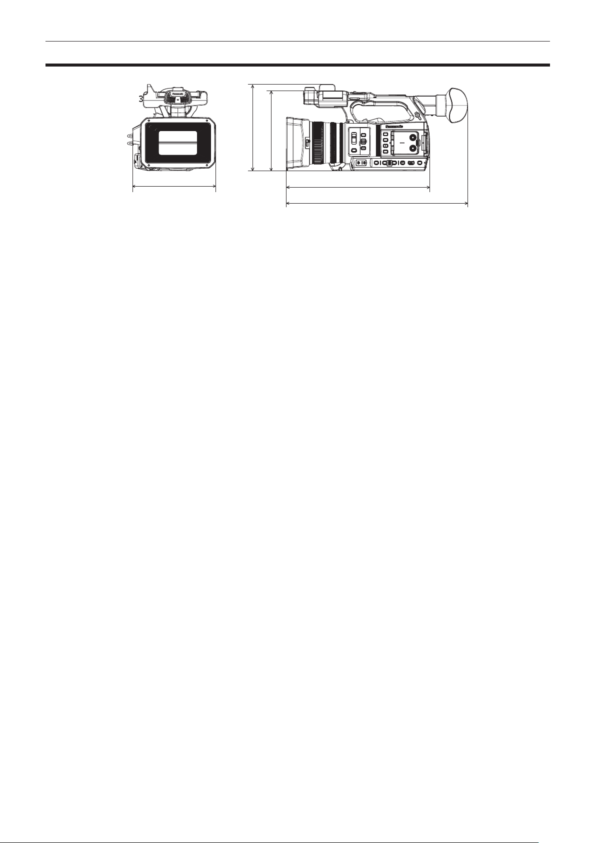
– 202 –
Chapter 11 Specication — Dimensions
Dimensions
180 mm (7-3/32 inches)
393 mm (15-15/32 inches)
311 mm (12-1/4 inches)
187 mm (7-11/32 inches)
173 mm (6-13/16 inches)

– 203 –
Chapter 11 Specication — Specications
Specications
General
Power
DC e 7.28 V (when battery is used)
DC e 12 V (when the AC adaptor is used)
Power consumption
17 W (when the LCD monitor is used)
indicates safety information.
Operating ambient temperature 0 °C – 40 °C (32 °F – 104 °F)
Operating ambient humidity 10% – 80% (relative humidity, no condensation)
Mass
Approx. 1.9 k] (4.19 lbs.) (body only, excluding lens hood, battery, and accessories)
Approx. 2.3 k] (5.07 lbs.) (including lens hood, battery, and accessories of microphone holder)
Dimensions (W×H×D)
Camera (including lens hood)
180 mm×173 mm×311 mm
(7-3/32 inches × 6-13/16 inches × 12-1/4 inches)
(excluding eye cup and protrusion)
Camera unit
Pickup device 1.0-inch MOS solid state image sensor
Number of pixels Number of effective pixels: Approx. 15.03 million pixels
Lens Optical image stabilizer lens, motorized 20x zoom
F2.8 – F4.5 (f=8.8 mm – 176 mm)
35 mm conversion: 24.5 mm – 490 mm (16:9)
Filter diameter 67 mm
Optical lter f ND lter
<CLR>, <1/4>, <1/16>, <1/64>
f IR cut lter
[ON]/[OFF] by assigning [IR REC] to the USER button (switched by menu)
Minimum object distance (M.O.D) 10 cm (wide angle) from the lens
1.0 m (telephoto angle) from the lens
Color temperature setting ATW, ATW LOCK, Ach, Bch, preset 3200 K/preset 5600 K/VAR (2000 K – 15000 K)
Gain setting <L>/<M>/<H> selector switch
−3 dB – 18 dB (1 dB step)
(When assigning [S.GAIN] to the USER button: Switching between 24 dB, 30 dB, and 36 dB)
Shutter speed
When the [SYSTEM] menu → [FREQUENCY] → [59.94Hz] is set
f 59.94i/59.94p mode:
1/60 sec. (shutter off), 1/100 sec., 1/120 sec., 1/250 sec., 1/500 sec., 1/1000 sec., 1/2000 sec., 1/4000
sec., 1/8000 sec., 1/10000 sec.
f 29.97p mode:
1/30 sec., 1/50 sec. (shutter off), 1/60 sec., 1/100 sec., 1/120 sec., 1/250 sec., 1/500 sec., 1/1000 sec.,
1/2000 sec., 1/4000 sec., 1/8000 sec., 1/10000 sec.
f 23.98p mode:
1/24 sec., 1/48 sec., 1/50 sec. (shutter off), 1/60 sec., 1/100 sec., 1/120 sec., 1/250 sec., 1/500 sec.,
1/1000 sec., 1/2000 sec., 1/4000 sec., 1/8000 sec., 1/10000 sec.
When the [SYSTEM] menu → [FREQUENCY] → [50.00Hz] is set
f 50i/50p mode:
1/50 sec. (shutter off), 1/60 sec., 1/100 sec., 1/120 sec., 1/250 sec., 1/500 sec., 1/1000 sec., 1/2000 sec.,
1/4000 sec., 1/8000 sec., 1/10000 sec.
f 25p mode:
1/25 sec., 1/50 sec. (shutter off), 1/60 sec., 1/100 sec., 1/120 sec., 1/250 sec., 1/500 sec., 1/1000 sec.,
1/2000 sec., 1/4000 sec., 1/8000 sec., 1/10000 sec.
Slow shutter speed
When the [SYSTEM] menu → [FREQUENCY] → [59.94Hz] is set
f 59.94i/59.94p mode:
1/1 sec., 1/2 sec., 1/4 sec., 1/6 sec., 1/15 sec., 1/30 sec.
f 29.97p mode:
1/1 sec., 1/2 sec., 1/4 sec., 1/6 sec., 1/15 sec.
f 23.98p mode:
1/1 sec., 1/2 sec., 1/4 sec., 1/6 sec., 1/12 sec.
When the [SYSTEM] menu → [FREQUENCY] → [50.00Hz] is set
f 50i/50p mode:
1/1 sec., 1/2 sec., 1/4 sec., 1/6 sec., 1/12 sec., 1/25 sec.
f 25p mode:
1/1 sec., 1/2 sec., 1/4 sec., 1/6 sec., 1/12 sec.

– 204 –
Chapter 11 Specication — Specications
Synchro scan shutter speed
When the [SYSTEM] menu → [FREQUENCY] → [59.94Hz] is set
f 59.94i/59.94p mode:
1/60.0 sec. – 1/7200 sec.
f 29.97p mode
1/30.0 sec. – 1/7200 sec.
f 23.98p mode
1/24.0 sec. – 1/7200 sec.
When the [SYSTEM] menu → [FREQUENCY] → [50.00Hz] is set
f 50i/50p mode:
1/50.0 sec. – 1/7200 sec.
f 25p mode
1/25.0 sec. – 1/7200 sec.
Shutter aperture angle 3.0 deg – 180.0 deg – 360.0 deg (in 0.5 deg steps, angle display)
VFR recording frame rate
f When the [SYSTEM] menu → [FREQUENCY] → [59.94Hz] is set
1, 2, 4, 6, 9, 12, 15, 18, 20, 21, 22, 24, 25, 26, 27, 28, 30, 32, 34, 36, 40, 44, 48, 54, 60 (frames per
second)
f When the [SYSTEM] menu → [FREQUENCY] → [50.00Hz] is set
1, 2, 4, 6, 9, 12, 15, 18, 20, 21, 22, 23, 24, 25, 26, 27, 28, 30, 32, 34, 37, 42, 45, 48, 50 (frames per
second)
Super slow recording
f [SYSTEM] menu → [FREQUENCY] → [59.94Hz]
When the number of recording pixels is 1920×1080 (FHD)
Shooting frame rate 120fps
f [SYSTEM] menu → [FREQUENCY] → [50.00Hz]
When the number of recording pixels is 1920×1080 (FHD)
Shooting frame rate 100fps
Sensitivity f [HIGH SENS.] mode
F12 (2000 lx, 3200 K, 89.9% reection, 2160/59.94p or 1080/59.94i)
F13 (2000 lx, 3200 K, 89.9% reection, 2160/50p or 1080/50i)
Memory card recorder
Recording media
f Card slot × 2
SDHC memory card (4 GB – 32 GB)
SDXC memory card (exceeding 32 GB – 128 GB)
: UHS-I/UHS-II, UHS Speed Class 3 compatible, video Speed Class V90 compatible
microP2 card (A series/B series)
Recording slot
microP2/SDXC UHS-II card slot × 2
Number of recording pixels
3840×2160 (UHD), 1920×1080 (FHD), 1280×720 (HD), 720×576 (SD), 720×480 (SD)
Recording le format P2 (P2 MXF compatible), MOV (HEVC), MOV (AVC), AVCHD
System frequency 59.94 Hz/50.00 Hz
Recording format f P2
AVC-Intra 422, AVC-LongG50, AVC-LongG25, AVC-LongG12
f MOV: 4:2:0 (10-bit)
HEVC LongGOP 200M/HEVC LongGOP 150M/HEVC LongGOP 100M
f MOV: 4:2:0 (8-bit)
420LongGOP 150M/420LongGOP 100M
f MOV: 4:2:2 (10-bit)
422LongGOP 150M/422LongGOP 100M/422LongGOP 50M
422ALL-I 400M/422ALL-I 200M/422ALL-I 100M
f AVCHD:
PS/PH/HA/PM/SA
Recording video signal
3840×2160/59.94p, 50p, 29.97p, 25p, 23.98p
1920×1080/59.94p, 50p, 29.97p, 25p, 23.98p, 59.94i, 50i
1280×720/59.94p, 50p
720×480/59.94i, 720×576/50i
Recording and playback time When using a 64 GB microP2 card
f 1080-59.94p/AVC-Intra 422
Approx. 32 minutes
f 1080-59.94i/AVC-LongG50
Approx. 2 hours 8 minutes
f 1080-59.94i/AVC-LongG25
Approx. 4 hours 16 minutes
When using a 64 GB SDXC memory card
f 3840×2160/420LongGOP 150M/59.94p, 50p
Approx. 55 minutes
f 1920×1080/420LongGOP 100M/59.94p, 50p
Approx. 1 hour 20 minutes
f 1920×1080/420LongGOP 50M/29.97p, 25p, 23.98p
Approx. 2 hours 40 minutes
Two‑slot function Simultaneous recording, relay recording, background recording

– 205 –
Chapter 11 Specication — Specications
Special recording Pre-recording, interval recording, time stamp recording
Digital video
Number of quantizing bits f P2:
4:2:2 (10-bit)/4:2:0 (8-bit (AVC-LongG12))
f MOV:
4:2:2 (10-bit)/4:2:0 (8-bit)/4:2:0 (10-bit (HEVC))
f AVCHD:
4:2:0 (8-bit)
Video compression format f P2:
AVC-Intra 422/AVC-LongG50/AVC-LongG25/AVC-LongG12, MPEG-4 AVC/H.264 Intra Prole
f MOV:
H.264/MPEG-4 AVC High Prole, H.265/MPEG-H HEVC Main10 Prole
Digital audio
Recording audio signal f P2:
48 kHz/24-bit, 4ch
48 kHz/16-bit, 4ch (only AVC-LongG12)
f MOV:
48 kHz/24-bit, 4ch
f AVCHD:
48 kHz/16-bit, 2ch
Audio recording format f P2:
LPCM
f MOV:
LPCM
f AVCHD:
Dolby Audio
TM
Headroom 12 dB/18 dB/20 dB switchable menu
Streaming
Video compression format H.264/MPEG-4 AVC Main Prole
H.264/MPEG-4 AVC High Prole
Video resolution
1920×1080 (FHD), 1280×720 (HD), 640×360, 360×180
Streaming method Unicast, Multicast
Frame rate
f When set to the [SYSTEM] menu → [FREQUENCY] → [59.94Hz]
30 fps, 60 fps
f When set to the [SYSTEM] menu → [FREQUENCY] → [50.00Hz]
25 fps, 50 fps
Bit rate 24 Mbps, 20 Mbps, 16 Mbps, 14 Mbps, 8 Mbps, 6 Mbps, 4 Mbps, 3 Mbps, 2 Mbps, 1.5 Mbps, 1 Mbps,
0.7 Mbps
Audio compression format AAC-LC: 48 kHz/16-bit, 2ch
Supported protocol RTSP/RTP/RTMP/RTMPS
Video output
<SDI OUT> terminal
f BNC×1
HD SDI: 0.8 V [p-p], 75 Ω
SD SDI: 0.8 V [p-p], 75 Ω
f SDI remote control support
f Output format (4:2:2 (10-bit) output)
1920×1080: 59.94p, 50p, 59.94i, 50i, 25PsF, 23.98PsF, 29.97PsF
1280×720: 59.94p, 50p
720×480: 59.94i
720×576: 50i
<HDMI> terminal
f HDMI type A×1 (not compatible with VIERA Link)
f HDMI remote control support
f Output format (4:2:2 (10-bit) output)
3840×2160: 59.94p, 50p, 29.97p, 25p, 23.98p
1920×1080: 59.94p, 50p, 59.94i, 50i, 29.97p, 25p, 23.98p
1280×720: 59.94p, 50p
720×480: 59.94p
720×576: 50p
<AV OUT> terminal 3.5 mm diameter mini jack
Composite: 1.0 V [p-p], 75 Ω
– 206 –
Chapter 11 Specication — Specications
Audio input/output
Built-in microphone Supports stereo microphone
<AUDIO INPUT 1>/<AUDIO INPUT 2> terminal
XLR×2, 3-pin
Input high impedance, <LINE>/<MIC>/<+48V> (switch selection)
f <LINE>:
4 dBu/0 dBu (menu selection)
f <MIC>:
−40 dBu/−50 dBu/−60 dBu (menu selection)
<SDI OUT> terminal LPCM 4ch
<HDMI> terminal LPCM 2ch
<AV OUT> terminal 3.5 mm diameter mini jack
Output level: 600 Ω, 316 mV
Headphone terminal
3.5 mm diameter stereo mini jack × 1
Speaker
20 mm diameter, round ×1
Other input/output
<TC IN/OUT> terminal
BNC×1
Used as input/output terminal, input/output switch by menu
f Input: 1.0 V – 4.0 V [p-p], 10 kΩ
f Output: 2.0 V±0.5 V [p-p], low impedance
<REMOTE> terminal
2.5 mm diameter super mini jack × 1
<USB2.0 HOST> terminal Type A connector, 4-pin (5 V, 0.5 A), for attaching the wireless module (optional)
<USB3.0 DEVICE> terminal USB 3.1 GEN1 type C connector, with USB mass storage function, without USB bus-powered function
<LAN> terminal RJ-45: 1000BASE-T/100BASE-TX/10BASE-T
<DC IN 12V> terminal DC12 V, EIAJ type 4
Monitor
LCD monitor 3.2-inch TFT LCD (3:2): Approx. 1620000 dots, touch panel compatible
Video display area (16:9): Approx. 1370000 dots
Viewnder 0.39-inch OLED (organic EL display) (4:3): Approx. 2360000 dots
Video display area (16:9): Approx. 1770000 dots
AC adaptor
Power source
AC d 100 V – 240 V, 50 Hz/60 Hz, 1.2 A
Power output
DC e 12 V, 3.0 A
indicates safety information.
Operating ambient temperature 0 °C – 40 °C (32 °F – 104 °F)
Operating ambient humidity 10% – 90% (relative humidity, no condensation)
Mass
Approx. 225 ] (0.496 lbs.)
Dimensions (W×H×D) 115 mm×37 mm×57 mm (4-1/2 inches × 1-7/16 inches × 2-1/4 inches) (excluding the DC cable section)
Battery charger (AG-BRD50)
Input voltage
DC e 12 V, 3.0 A
Output voltage
DC e 8.4 V, 4.0 A
indicates safety information.
Charging current Maximum 4000 mA
Operating ambient humidity 10% – 80% (relative humidity, no condensation)
Mass
Approx. 230 ] (0.507 lbs.)
Dimensions (W×H×D) 130 mm×48 mm×107 mm (5-1/8 inches × 1-7/8 inches × 4-3/16 inches)
Battery pack (AG-VBR59)
Voltage/capacity
DC e 7.28 V/5900 mAh 43 Wh
indicates safety information.

– 207 –
Chapter 11 Specication — Specications
Charging current Maximum 4000 mA
Operating ambient humidity 10% – 80% (relative humidity, no condensation)
Mass
Approx. 230 ] (0.507 lbs.)
Dimensions (W×H×D) 41.3 mm×51.3 mm×69.6 mm (1-5/8 inches × 2 inches × 2-3/4 inches)

Index
– 208 –
Index
A
AC adaptor
Attaching
33
Accessory
Mounting
37
Area mode function
120
ATW
122
Audio input
130
Audio device
130
Built-in microphone
130
Conrming setting
132
External microphone
130
Level adjustment
131
Monitor
131
Switching
130
Auto tracking white balance
122
B
Back balance
122
Background recording
135
Battery
Charging
30
Mounting
32
Removing
32
Black control function
127
Brightness adjustment
119
Built-in battery
39
C
Camera image screen
60, 160
Card reader mode
172
Center marker
137
Chroma setting function
126
Clip
Copying
150
Deleting
151
Playback
153
Protecting
152
Restoring
152
Clock
40
Color bars
142
Color correction function
127
CX ROP app
182
D
Date and time
40
Detail function
125
Digital zoom function
141
Dynamic range stretcher function
140
E
Error message
194
External microphone
Mounting
36
Eye cup
35
Eye sensor
55
F
Focus assist function
138
Frame marker
138
G
Gain
119
Gamma function
127
H
Headphones
170
High-speed shooting
129
I
Interval recording
136
Iris
119
IR recording
136
K
Knee function
128
L
LCD monitor
54
Status display
160
Lens cover
35
Lens hood
34
Level gauge
142
M
Macro
119
Manual focus
119
Matrix function
126
Memory card
41
Data structure
44
Format
43
Insert
42
Recording time
43
Remove
42
Status
42
Write-protected
42
Menu
[AUDIO]
79
[CAMERA]
65
Conguration
61
Display
62
Initialization
64
[NETWORK]
92
Operation
63
[OPTION]
101
[OTHERS]
99
[RECORDING]
90
[SCENE FILE]
69
[SYSTEM]
98
[THUMBNAIL]
65
[VIDEO OUT/LCD/VF]
81
Mirror shooting
54
Mode check
166
Monitor
171
Multi manual function
144
N
ND lter
119
Network
175
Wired LAN
176
Wireless LAN
176
O
Operation icon screen
143
Optical image stabilizer function
140
Output format
<HDMI> terminal
158
<SDI OUT> terminal
158
P
P2 Cast
190
Power
How to turn off the power
38
How to turn on the power
38
Pre-recording
133
R
RB gain control function
125
Relay recording
133
Remote control
170
Remote operation
173
Resume play
155
S
Safety zone marker
138
Scene les
112
Screen display
58
Setup le
113

Index
– 209 –
Shooting
116
Shoulder strap
34
Simultaneous recording
134
Skin tone function
125
Specications
203
Still image recording function
156
Streaming function
184
Super gain
119
Super slow
129
Switching screen
59
T
Tally lamp
56
Thumbnail
147
Thumbnail screen
147
Time code
49
External preset
50
Supplying to external
51
Time data
48
Time stamp function
140
Tripod
36
TV
171
U
Update
199
Usage restriction
198
USB
172
User bits
48
USER buttons
Assignment
52
Check
53
V
Variable frame rate
129
Viewnder
55
W
Warning system
194
Waveform monitor function
141
White balance
121
White clip function
128
Wireless LAN
Direct connection
177
Wireless access point
177
Wireless module
182
Z
Zebra patterns
137
Zoom
124

Web Site: http://www.panasonic.com
©Panasonic Corporation 2019