Loading ...
Loading ...
Loading ...
Assembly (continued)
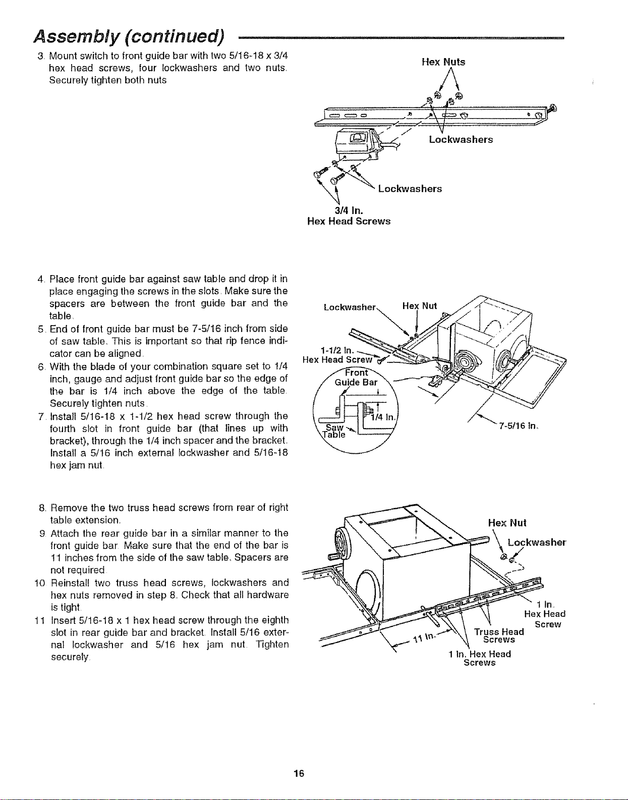
3 Mount switch to front guide bar with two 5/16-!8 x 3/4
hex head screws, tour lockwashers and two nuts_
Securely tighten both nuts
Hex Nuts
,, 1 Lockwashers
_'_ _ Loekwashers
3/4 In.
Hex Head Screws
4 Place front guide bar against saw table and drop it in
place engaging the screws in the slots, Make sure the
spacers are between the front guide bar and the
table
5 End of front guide bar must be 7-5/16 inch from side
of saw table, This is important so that rip fence indi-
cator can be aligned
6 With the blade of your combination square set to 1/4
inch, gauge and adjust front guide bar so the edge of
the bar is 1/4 inch above the edge of the table,
Securely tighten nuts,
7 Install 5/16-18 x 1-1/2 hex head screw through the
fourth slot in front guide bar (that lines up with
bracket), through the 1/4 inch spacer and the bracket,
Install a 5/16 inch external lockwasher and 5/16-t8
hex jam nut,
Lockwasher Hex Nut
1-1/2In.
Hex Head Screw
@
7-5!16 |no
8. Remove the two truss head screws from rear of right
table extension,
9 Attach the rear guide bar in a similar manner to the
front guide bar Make sure that the end of the bar is
11 inches from the side of the saw table, Spacers are
not required
10 Reinstall two truss head screws, tockwashers and
hex nuts removed in step 8. Check that all hardware
is tight
11 insert 5/16-18 x 1 hex head screw through the eighth
slot in rear guide bar and bracket, Install 5/16 exter-
nal Iockwasher and 5/16 hex jam nut Tighten
securely
Hex Nut
Lockwas her'
t In,
Hex Head
Screw
Truss Head
Screws
1 In. Hex Head
Screws
16
Loading ...
Loading ...
Loading ...