Loading ...
Loading ...
Loading ...
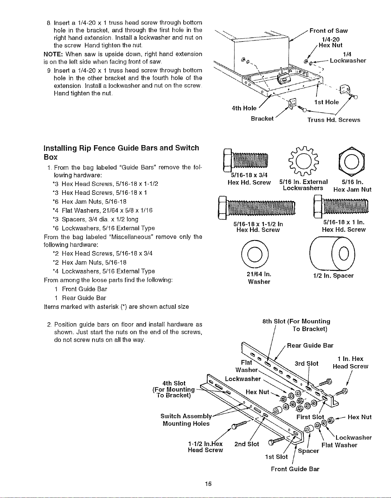
8 Inserta 1/4-20x 1trussheadscrewthroughbottom
holeinthebracket,andthroughthefirstholein the
righthandextension.Installalockwasherandnuton
thescrewHandtightenthenut
NOTE:Whensawisupsidedown,righthandextension
isontheleftsidewhenfacingfrontofsaw
9 Inserta 1/4-20x 1trussheadscrewthroughbottom
holein the other bracket and the fourth hole of the
extension Install a Iockwasher and nut on the screw
Hand tighten the nut.
Bracket
j Front of Saw
1/4-20
Hex Nut1/4
_ ¢._---- Lockwasher
1st Hole
Truss Hd. Screws
Installing Rip Fence Guide Bars and Switch
Box
1. From the bag labeled "Guide Bars" remove the fol-
lowing hardware:
*3 Hex Head Screws, 5/16-18 x 1-t/2
*3 Hex Head Screws, 5/16-I8 x 1
*6 Hex Jam Nuts, 5/I6-18
*4 Flat Washers, 21/64 x 5/8 x 1/16
*3 Spacers, 3/4 dia, x 1/2 long
*6 Lockwashers, 5/16 External Type
From the bag labeled "Miscellaneous" remove only the
following hardware:
*2 Hex Head Screws, 5/16-18 x 3/4
*2 Hex Jam Nuts, 5/16-18
*4 Lockwashers, 5/t6 External Type
From among the loose parts find the following:
1 Front Guide Bar
1 Rear Guide Bar
Items marked with asterisk (*) are shown actual size
5/16-18 x 3/4
Hex Hd. Screw
5/16 In. External
Lockwashers
5116-18 x 1-1/2 In
Hex Hd. Screw
G
5/16 In.
Hex Jam Nut
5/16-18 x 1 In.
Hex Hd. Screw
21164 In. 1/2 In. Spacer
Washer
2. Position guide bars on floor and install hardware as
shown,. Just start the nuts on the end of the screws,
do not screw nuts on all the way,
8th Slot (For Mounting
To Bracket)
/ Rear Guide Bar
, ¢ 1 In Hex
• FI_ _ 3rd Slot Head'Screw
wasner.._ __ l
(ForMounting __'_ Hex Nut __--_
ToBracko,
1-112 ln.Hex 2rid Slot t_'_ ._ / Flat Washer
Head Screw 1st SIo_t I Spacer
Front Guide Bar
15
Loading ...
Loading ...
Loading ...