Loading ...
Loading ...
Loading ...
ENGLISH
6
loaded pins on the floor extension are fully engaged in the
holes on the floor cleaning head.
Attaching and Removing the Hand Held Steam
Unit to and from the Floor Extension (Fig. C)
WARNING: Inspect the seal between the connection
point on the hand held steam unit 3 and the floor
extrension 7 before each use. If the seal malfunctions or
is damaged, please contact your nearest authorized repair
agent. Do not use the appliance.
1. To attach, push the hand held steam unit 3 firmly onto
the floor extension 7 making sure it sits correctly over
the interface and clicks securely into place.
NOTE: Floor extension is keyed and will only insert into
hand held steam unit in one orientation.
2. To remove, push the floor extension release button 6 on
the floor extension 7 and lift the hand held steam unit 3
off the interface.
Attaching a Cleaning Pad (Fig. D)
Replacement cleaning pads are available from your local
BLACK+DECKER dealer :- (cat no. SMP20).
CAUTION: Never leave the floor cleaning head in one
spot on any surface for any period of time. Always place
the hand held steam unit with attached floor extension
and floor cleaning head supported in the upright
position when stationary and make sure the hand held
steam unit is turned off when not in use.
1. Place a cleaning pad 24 on the floor with the loop side
facing up.
2. Lightly press the floor cleaning head down onto the cleaning pad.
Removing a Cleaning Pad (Fig. D)
CAUTION: Always wear suitable shoes when changing
the cleaning pad on your floor cleaning head.
CAUTION: Never leave the floor cleaning head in one
spot on any surface for any period of time.
1. Do not wear slippers or open toed footwear.
2. Return the hand held steam unit with attached floor
extension and floor cleaning head to the upright position
and turn the hand held steam unit OFF.
3. Wait until the hand held steam unit cools down for
approximately five minutes.
4. Lift the floor cleaning head away from the cleaning pad
24
freeing it from the hook and loop fastening by putting
weight on the cleaning pad removal tab
25 with your shoe.
5. Always place the hand held steam unit with attached
floor extension and floor cleaning head supported in
the upright position when stationary and make sure the
hand held steam unit is turned off when not in use.
Filling the Water Tank (Fig. E)
WARNING: When filling, maintain the water tank 5 in
a vertical position with the cap at the top.
WARNING: Your water tank has a 17 fl oz (0.5 liter)
capacity. Do not over fill the tank.
NOTE: Do not use chemical cleaners with your hand held
steam unit watertank.
Attaching the Floor Extension to the Floor
Cleaning Head (Fig. B)
1. Push the floor extension 7 into the floor cleaning head 8
making sure it clicks securely into place, as shown in Fig. B.
NOTE: The cross section of the floor extension is more
rounded on one side and will only insert in one orientation
into the floor cleaning head. Ensure that both spring
ASSEMBLY AND ADJUSTMENTS
WARNING: To reduce the risk of serious personal
injury, turn unit off and disconnect it from
power source before making any adjustments or
removing/installing attachments or accessories.
An accidental start-up can causeinjury.
WARNING: Before attempting any of the following
operations, make sure that the appliance is switched
off and unplugged and that the appliance is cold and
contains minimal or nowater.
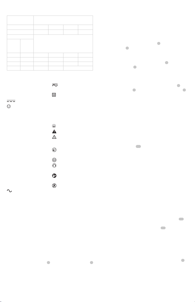
The label on your tool may include the following symbols. The
symbols and their definitions are asfollows:
V ......................... volts
Hz .......................hertz
min ..................... minutes
or DC ......direct current
...................... Class I Construction
(grounded)
…/min ..............per minute
BPM .................... beats per minute
IPM ..................... impacts per minute
OPM .................... oscillations per
minute
RPM .................... revolutions per
minute
sfpm ................... surface feet per
minute
SPM .................... strokes per minute
A ......................... amperes
W ........................watts
Wh ......................watt hours
Ah ....................... amp hours
or AC ...........alternating current
or AC/DC .... alternating or direct
current
...................... Class II Construction
(double insulated)
no .......................no load speed
n .........................rated speed
PSI....................... pounds per square
inch
......................earthing terminal
.....................safety alert symbol
..................... visible radiation
do not stare into
the light
..................... wear respiratory
protection
..................... wear eye protection
..................... wear hearing
protection
..................... read all
documentation
..................... do not expose to
rain
Minimum Gauge for Cord Sets
Volts Total Length of Cord in Feet
(meters)
120 V 25 (7.6) 50 (15.2) 100 (30.5) 150 (45.7)
240 V 50 (15.2) 100 (30.5) 200 (61.0) 300 (91.4)
Ampere Rating
American Wire Gauge
More
Than
Not
More
Than
0 6 18 16 16 14
610 18 16 14 12
10 12 16 16 14 12
12 16 14 12 Not Recommended
Loading ...
Loading ...
Loading ...