Loading ...
Loading ...
Loading ...
Function Inspection
1. Press the Default button on the front panel to restore the instrument to its
default configuration.
2. Connect the ground alligator clip of the probe to the “Ground Terminal”
under the probe compensation signal output terminal.
Compensation Signal
3. Use the probe to connect the input terminal of CH1 of the oscilloscope and the
“Compensation Signal Output Terminal” of the probe.
4. Press the Auto Setup.
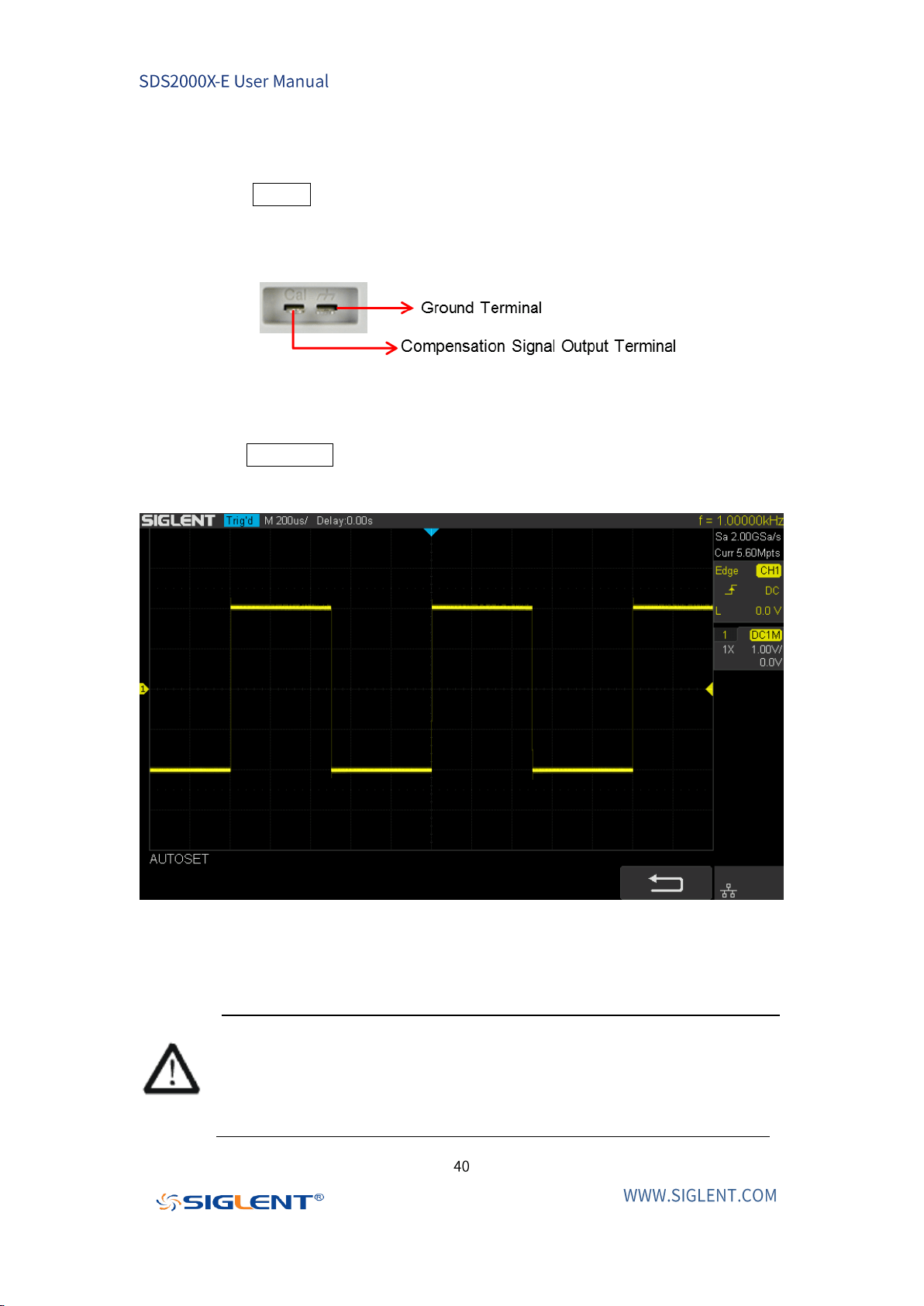
5. Observe the waveform on the display. In normal operating conditions, the
display should be a square waveform as shown in the figure below:
Figure 5 Functional Inspection
6. Use the same method to test the other channels. If the square waveforms
actually shown do not match that in the figure above, please perform “Probe
Compensation” in the next section.
WARNING
To avoid electric shock while using probes, please make sure that the
insulated wire of the probe is in good condition and do not touch the
metallic part of the probe when the probe is connected to high voltage
source.
Loading ...
Loading ...
Loading ...