Loading ...
Loading ...
Loading ...
15 English
1. Settings for optional accessories
• In case of connecting optional accessories, refer to the
installation manual provided with them and make neces-
sary settings.
2. External static pressure settings
Make settings in either method (a) or method (b) as
explained below.
(a) Use the airflow adjustment function to make settings.
Automatic airflow adjustment: The volume of discharge
air is automatically adjusted to the rated quantity.
(1) Check that power supply wiring to the air conditioner
is completed along with duct installation. If a closing
damper is installed in the air-conditioning system,
make sure that the closing damper is opened. Fur-
thermore, check that the air filter as a field supply is
attached to the air passage on the suction side.
(2) If there are a number of air outlets and inlets, adjust the
throttles so that the airflow rate of each air outlet and
inlet will coincide with the designed airflow rate. At that
time, operate the air conditioner in “fan mode”. To
change the airflow rate, press and set the airflow adjust-
ment button of the remote controller to H, M, or L.
(3) Make settings for automatic airflow adjustment. After
setting the air conditioner to “fan mode”, stop the air
conditioner, go to “Field Settings”, select Mode No.
“21” (11 in the case of group settings), set the setting
“FIRST CODE NO.” to 7, and set the setting “SEC-
OND CODE NO.” to 03.
Return to normal mode after these settings, and press
the on/off button. Then the operation lamp will be lit
and the air conditioner will go into fan operation for
automatic airflow adjustment. Do not adjust the throt-
tles of the air outlets or inlets during automatic adjust-
ment of the air conditioner. After the air conditioner
runs approximately one to eight minutes, the air con-
ditioner will finish airflow adjustment automatically, the
operation lamp will be turned OFF, and the air condi-
tioner will come to a stop.
Table 2
(4) After the air conditioner stops operating, check with
“Mode No. 21” on an indoor unit basis that 02 is set
for the “SECOND CODE NO.” in Table 2. If the air
conditioner does not stop operating automatically or
the “SECOND CODE NO.” is not 02, repeat steps
from (3). If the outdoor unit is not turned ON, U4 or
UH as explained in Table 5 will be displayed. This dis-
play is not problematic, because this function is set
for the indoor unit. Continue setting the function.
After setting this function, be sure to turn ON the out-
door unit before the test operation of the outdoor unit.
If any other error is displayed, refer to Table 5 and the
installation manual provided with the outdoor unit
and check the defective point.
CAUTION
• If there is any change after airflow adjustment in the ventila-
tion paths (e.g., the duct and air outlet), be sure to make auto-
matic airflow adjustment again.
• Consult your Daikin representative if there is any change in
the ventilation paths (e.g., the duct and air outlet) after the test
operation of the outdoor unit is finished or the air conditioner
is moved to another place.
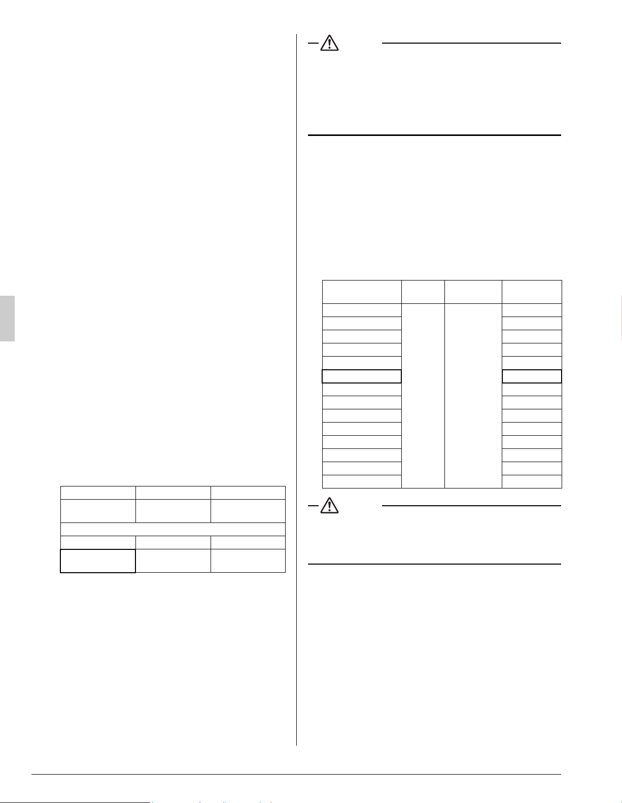
(b) Select an external static pressure with the remote con-
troller.
Check that 01 (OFF) is set for the “SECOND CODE NO.”
in “Mode No. 21” for airflow adjustment on an indoor unit
basis in Table 2. The “SECOND CODE NO.” is set to 01
(OFF) at factory set. Change the “SECOND CODE NO.”
as shown in Table 3 according to the external static pres-
sure of the duct to be connected.
(1) The “SECOND CODE NO.” is set to 07 (an external
static pressure of 0.4 inWG) at factory set.
Table 3
CAUTION
Keep in mind that a shortage of airflow quantity or water leakage
will result because the air conditioner will be operated outside
the rated range of airflow quantity if the external static pressure
is wrongly set.
Mode No. FIRST CODE NO. Setting contents
21 7
Airflow
adjustment
SECOND CODE NO.
01 02 03
OFF
Completion of
airflow adjustment
Start of airflow
adjustment
External Static
Pressure
Mode No.
FIRST
CODE NO.
SECOND
CODE NO.
0.20 inWG (50 Pa)
23 06
02
0.24 inWG (60 Pa)
03
0.28 inWG (70 Pa)
04
0.32 inWG (80 Pa)
05
0.36 inWG (90 Pa)
06
0.40 inWG (100 Pa)
07
0.44 inWG
(110 Pa)
08
0.48 inWG
(120 Pa)
09
0.52 inWG
(130 Pa)
10
0.56 inWG
(140 Pa)
11
0.60 inWG
(150 Pa)
12
0.64 inWG
(160 Pa)
13
0.72 inWG
(180 Pa)
14
0.80 inWG
(200 Pa)
15
01_EN_3P530815-1.fm Page 15 Tuesday, July 10, 2018 6:20 PM
Loading ...
Loading ...