Loading ...
Loading ...
Loading ...
English 14
[ PRECAUTIONS ]
1. Do not ground the equipment on gas pipes, water pipes or
lightning rods, or crossground with telephones.
Improper grounding could result in electric shock.
2. The remote controller wiring (P
1 and P2) and transmission
wiring (F1 and F2) have no polarity.
10-3
CONTROL BY 2 REMOTE CONTROLLERS (Con-
trolling 1 indoor unit by 2 remote controllers)
• When using 2 remote controllers, one must be set to “MAIN”
and the other to “SUB”.
Main/sub changeover
• Refer to the installation manual supplied with the remote con-
troller.
Wiring method
(1) Remove the control box cover.
(2) Add the remote controller 2 (SUB) to the terminal block for
remote controller (P
1, P2) in the control box. (There is no
polarity.)
10-4 REMOTE CONTROL (FORCED OFF AND ON/
OFF OPERATION)
(1) Wire specifications and how to perform wiring
• Connect input lines from the outside to the terminals T
1
and T2 on the terminal block (6P) for remote controller to
achieve remote control.
•See “11. FIELD SETTING” for details on operation.
(2) Actuation
• The following table explains FORCED OFF and ON/OFF
OPERATIONS in response to Input A.
(3) How to select FORCED OFF and ON/OFF OPERATION
• Turn the power on and then use the remote controller to
select operation.
10-5 CENTRALIZED CONTROL
• For centralized control, it is necessary to designate the group
No. For details, refer to the manual of each optional control-
lers for centralized control.
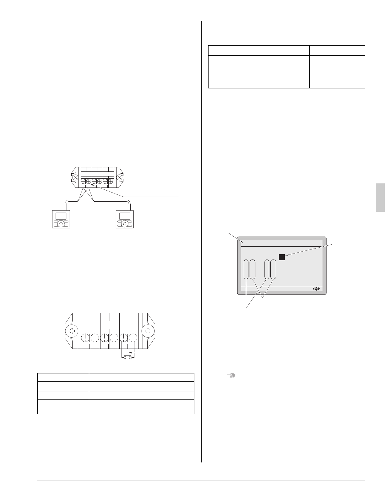
11. FIELD SETTING
Make sure the control box covers are closed on the indoor
and outdoor units.
Field setting must be made from the remote controller in
accordance with the installation conditions.
• Setting can be made by changing the “Mode No.”, “FIRST
CODE NO.”, and “SECOND CODE NO.”.
• For setting procedures and instructions, refer to the “Field
Settings” in the installation manual of the remote controller.
With wireless remote controller used
Set the wireless remote controller address before using the
wireless remote controller.
For the setting method of the address, refer to the operation
manual provided with the wireless remote controller.
NOTE
• Before the test operation as explained in 12. TEST OPERA-
TION, be sure to make the following field settings.
• A “Mode No.” is set on a group basis. To make a mode setting
on an individual unit basis or check the setting made, how-
ever, set the corresponding mode number in the parenthe-
ses.
Wire specification Sheathed vinyl cord or 2 core cable
Gauge
AWG18 – 16 (0.75-1.25 mm
2
)
Length Max. 328 ft. (100 m)
External terminal
Contact that can ensure the minimum appli-
cable load of 15 V DC, 1 mA.
1
P
2
P
1
F
2
F
1
T
2
T
FORCED
OFF
REMOTE
CONTRL
TRANSMISSION
WIRING
Remote controller wiring
terminal block
Remote
controller 2
(SUB)
Remote
controller 1
(MAIN)
Fig. 11
Input A
1
P
2
P
1
F
2
F
1
T
2
T
FORCED
OFF
REMOTE
CONTRL
TRANSMISSION
WIRING
Fig. 12
FORCED OFF ON/OFF OPERATION
Input “ON” stops operation (impossible by
remote controllers.)
Input OFF ON turns
ON unit.
Input OFF enables control by remote con-
troller.
Input ON OFF turns
OFF unit.
Unit No.
0
1
–
01
5
–––
9
–––
2
–
02
6
–––
a
–––
3
–
01
7
–––
b
–––
Field Settings
0
–
01
4
–––
8
–––
Setting
Mode
20
SECOND CODE NO.
FIRST CODE NO.
Mode No.
FIELD SET MODE
Fig. 13
01_EN_3P530815-1.fm Page 14 Tuesday, July 10, 2018 6:20 PM
Loading ...
Loading ...
Loading ...