Loading ...
Loading ...
Loading ...
13 English
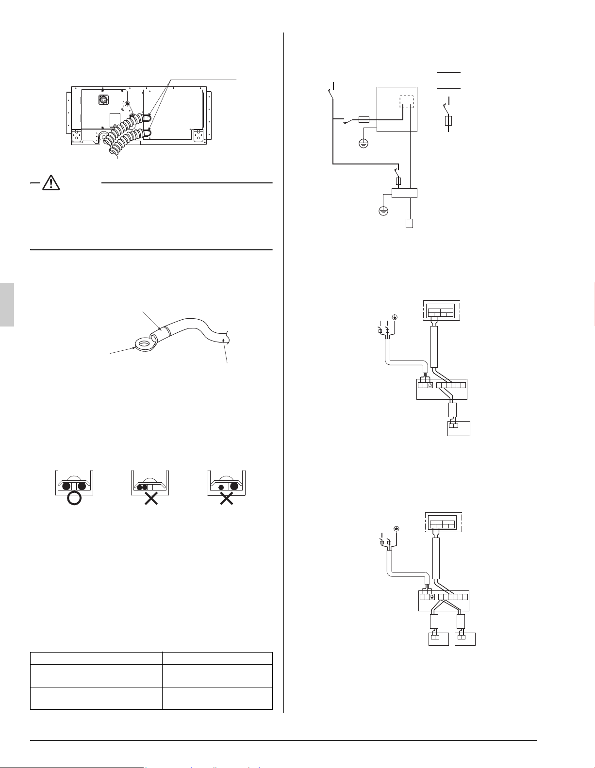
(4) Put the control box cover, and wrap the wire sealing mate-
rial (Small) (10) around the conduit so as to block the wire
through holes.
CAUTION
• After all the wiring connections are done, fill in any gaps in the
through holes with putty or insulation (procured locally) to pre-
vent small animals and insects from entering the unit from
outside. (If any does get in, they could cause short circuits in
the control box.)
[Precautions for Power Supply Wiring]
• Connect round crimp-style terminals provided with insulation
sleeves to the terminal block for power supply.
Be sure to follow the instructions provided below if the spec-
ified terminals cannot be used.
Otherwise, abnormal heat may be generated as a result
of the loosening of the wires.
• If stranded wires are used, do not solder the front end of the
wires.
• Connect proper wires securely and fix the wires so that exter-
nal force will not be imposed on the terminals.
• Use an appropriate screwdriver to tighten the terminal
screws. The screw heads may be damaged if the screwdriver
is too small and the terminal screws will not be tightened
properly.
• Do not tighten the terminal screws excessively, or otherwise
the screw heads may be damaged.
• Refer to the table below for the required tightening torque val-
ues of the terminal screws.
10-2 WIRING EXAMPLE
COMPLETE SYSTEM EXAMPLE
1. When using 1 remote controller (Normal operation)
2. When using 2 remote controllers
Tightening torque [lbf·ft (N·m)]
Terminal block for remote controller
and transmission wires
0.59 - 0.71
(0.80 - 0.96)
Terminal block for power supply
Ground wiring
0.98 - 1.19
(1.33 - 1.61)
Wire through holes
Electric wire
Round crimp-style terminal
Attach insulation sleeve
Connect the wires
evenly.
Do not connect a
wire to the single
side only.
Do not connect
wires different
from each other in
diameter.
Outdoor unit
Indoor unit
Remote controller
Power supply
Main
switch
Power supply wire
Transmission wire
Disconnect switch
Fuse/Breaker
Fig. 8
L
1
L
2
IN/D OUT/D
F
1
F
2
F
1
F
2
P
1
P
2
P
1
P
2
F
1
F
2
T
1
T
2
Control box
208/230V
1~ 60Hz
Outdoor unit
Indoor unit
L
1
L
2
Fig. 9
Power Supply
Remote
controller
P
1
P
2
P
1
P
2
L1L2
IN/D OUT/D
F
1
F
2
F
1
F
2
P
1
P
2
F
1
F
2
T
1
T
2
Control box
208/230V
1~ 60Hz
Outdoor unit
Indoor unit
L
1
L
2
Fig. 10
Power Supply
For use with
2 remote
controllers
01_EN_3P530815-1.fm Page 13 Tuesday, July 10, 2018 6:20 PM
Loading ...
Loading ...
Loading ...