Specifications
120VAC 50/60Hz
15A resistive
1200W tungsten
5A/600W electronic ballast/LED
1/2HP motor
Installation instructions
If you are uncomfortable with installation, contact a qualified
electrician.
• For supply connections, use 14AWG or larger wires suitable for at
least 75° C.
• For grounding lead use 12AWG or larger wires suitable for at least
75° C.
• Tighten wire connections to 12.4lbf-in. (5.6kg).
• Use copper wire only.
• Recommended wire-strip length – 5/8in. (16mm).
• Use screw-terminal holes – do not wrap wires around screws.
• Indoor single-pole installation only.
1. Turn power o at circuit breaker or fuse box before installation.
2. Remove wallplate and switch from switch box.
3. Identify the line, load, neutral and ground wires.
4. Connect the green or bare copper ground wire to the GROUND
terminal.
5. Connect the black line (hot) wire to the LINE terminal.
6. Connect the black load wire to the LOAD terminal.
7. Connect the white neutral wire to the NEUTRAL terminal – use
provided jumper if needed. Often the neutral wire (white) can be
found in the back of the wire box connected with a wire nut.
8. Insert the motion-sensing switch into the switch box being
careful to not pinch or crush wires.
9. Secure the switch to the switch box using the provided
mounting screws.
10. Replace door if light-almond color is desired. Insert a flat-blade
screwdriver into either groove in the lower corner of the sensor
and gently pry up the door. Repeat on the opposite side to
remove the door from the sensor. Align the hooks of the
replacement door with the hooks at the bottom of the sensor
and snap the bottom tabs into place.
11. Install a rocker-style wallplate – not included.
12. Turn the power on at the circuit breaker or fuse box.
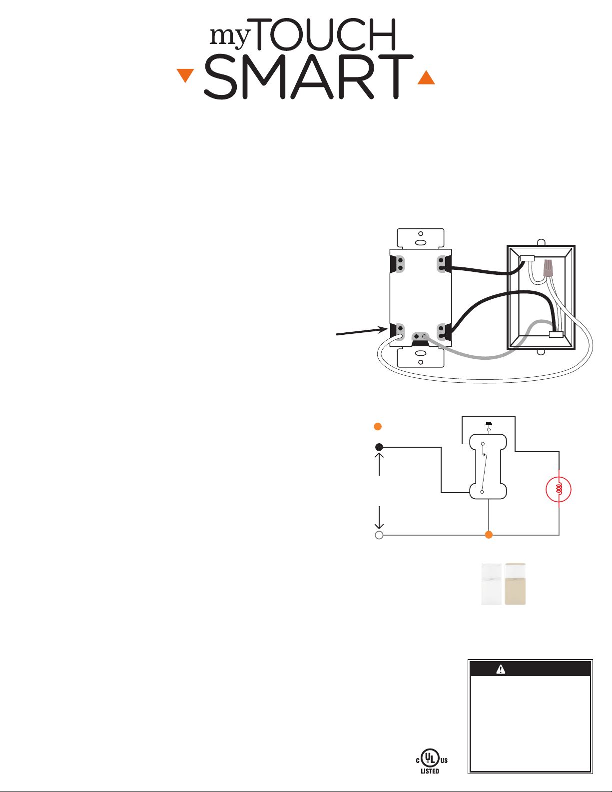
Typical SPST Installation
Figure 1
Black
Load
Black
Line
Green
Ground
LINE
NEUTRAL
GROUND
White
Neutral
JUMPER WIRE
TOP
LOAD
= Wiring Nut
Line
NO
Load
C
Black
Line
Load
Black
Black
Light
WhiteWhite
120VAC
Power
Source
RISK OF ELECTRIC SHOCK
• SHUT OFF POWER AT FUSE BOX OR
CIRCUIT BREAKER BEFORE INSTALLATION
• DO NOT USE IN WET LOCATIONS
• USE INDOORS ONLY
RISK OF FIRE
• DO NOT USE TO CONTROL APPLIANCES
THAT CONTAIN HEATING ELEMENTS
(COOKING APPLIANCES, HEATERS, IRONS,
ETC.)
• DO NOT EXCEED ELECTRICAL RATINGS
• USE COPPER WIRE ONLY WITH THIS
DEVICE
• DO NOT USE TO CONTROL RECEPTACLES
WARNING
Works with dimmable
LED and CFL bulbs.
In-Wall
Motion-Sensing
Switch
MADE IN CHINA
Distributed by Jasco Products Company LLC, 10 E. Memorial Rd.,
Oklahoma City, OK 73114.
This Jasco product comes with a 1-year limited warranty.
Visit www.byjasco.com for warranty details product registration.
Questions? Contact our U.S.-based Consumer Care at
1-800-654-8483 between 7AM—8PM, M-F, Central Time.
White & light almond
faceplates included
41381 WIRING MANUAL V1
04/08/20
Especificaciones:
120VCA 50/60Hz
15A resistiva
1200 tungsteno
5A/600W balasto electrónico/LED
1/2HP motor
Instrucciones de instalación
Si no se siente capacitado para realizar la instalación, llame a un
electricista habilitado.
• En el caso de las conexiones de suministro, use cables 14AWG o más
grandes para 75° C, como mínimo.
• En el caso del cable a tierra, use cables 12AWG o más grandes para
75° C, como mínimo.
• Fije las conexiones de los cables a 12 lbf-pulg. (14 Kgf-cm).
• Solo use cables de cobre.
• Longitud recomendada del pelado del cable: 16 cm (5/8 pulgadas).
• Use orificios de terminal de tornillos: no enrosque los cables en los
tornillos.
• Solo instalación de un solo poste en interiores.
1. Apague la alimentación en el disyuntor o la caja de fusibles antes de
la instalación.
2. Retire la placa de pared y el interruptor de la caja del interruptor.
3. Identifique los cables de línea, carga, neutro y a tierra.
4. Conecte el cable a tierra de cobre verde o pelado al terminal
GROUND (a tierra).
5. Conecte el cable de línea negro (energizado) al terminal LINE (línea).
6. Conecte el cable de carga negro al terminal LOAD (carga).
7. Conecte el cable blanco neutro al terminal NEUTRAL (neutro). De ser
necesario, use el cable de puente proporcionado.
8. Inserte el interruptor de detección de movimiento dentro de la caja
del interruptor teniendo cuidado de no pellizcar ni aplastar los cables.
9. Fije el interruptor a la caja del interruptor con los tornillos de montaje
provistos.
10. Reemplace la tapa si prefiere la de color almendra claro. Inserte un
destornillador de cabeza plana en cualquier ranura de la esquina
inferior del sensor y abra la tapa haciendo palanca suavemente.
Repita en el lado opuesto para retirar la tapa del sensor. Alinee los
ganchos de la tapa de reemplazo con los ganchos en la parte inferior
del sensor para fijar a presión las lengüetas inferiores en su lugar.
11. Instale una placa de pared de estilo basculante (no se incluye).
12. Conecte la energía en el disyuntor o la caja de fusibles.
Funciona con bombillas
atenuables LED y CFL.
HECHO EN CHINA
Distribuido por Jasco Products Company LLC, 10 E. Memorial Rd.,
Oklahoma City, OK 73114.
Este producto de Jasco tiene una garantía limitada de un (1) año.
Visite www.byjasco.com para conocer los detalles de la garantía.
¿Preguntas? Comuníquese con nuestro Centro de atención al
cliente con sede en EE.UU. al 1-855-698-8324, de lunes a viernes,
de 7:00 a.m. a 8:00 p.m. CST (hora central estándar).
Se incluyen placas
frontales de color
blanco y almendra
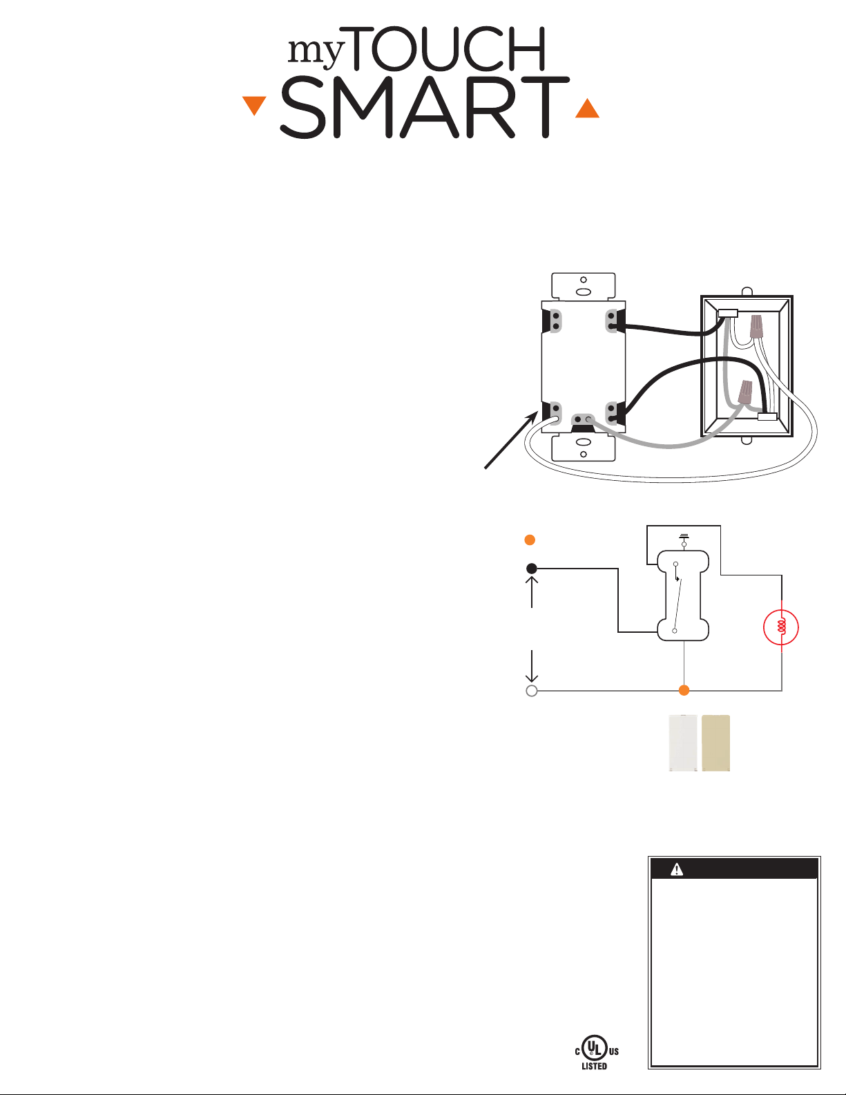
Instalación normal para contactos
unipolares de una vía (SPST)
Figura 1
Negro
Carga
Negro
Línea
Verde
Tierra
LINE
NEUTRAL
GROUND
Blanco
Neutro
CABLE PUENTE
TOP
LOAD
= Empalme de cable
Negro
Negro
Negro
Luz
BlancoBlanco
Fuente de
energía
120 VCA
Linea
NA
Carga
C
Tierra
Verde
RIESGO DE DESCARGA ELÉCTRICA
• INTERRUMPA EL SUMINISTRO ELÉCTRICO
DESDE EL PANEL DE FUSIBLES O EL
DISYUNTOR ANTES DE PROCEDER A LA
INSTALACIÓN.
• NO UTILICE EL DISPOSITIVO EN LUGARES
HÚMEDOS
• SOLO PARA USO EN INTERIORES
RIESGO DE INCENDIO
• NO UTILICE EL DISPOSITIVO PARA
CONTROLAR APARATOS QUE INCLUYAN
RESISTENCIAS ELÉCTRICAS (APARATOS
DE COCCIÓN, CALEFACTORES,
PLANCHAS, ETC.).
• NO SUPERE LOS VALORES NOMINALES
ELÉCTRICOS.
• USE SOLO CABLES DE COBRE CON ESTE
DISPOSITIVO.
• NO UTILICE EL DISPOSITIVO PARA
CONTROLAR TOMACORRIENTES.
ADVERTENCIA
Interruptor de
detección de
movimiento
empotrado
