Loading ...
Loading ...
Loading ...
Operation
BEFORECOOKING
[] [] [] [] [] [] [] [] [] [] [] [] [] [] [] [] [] [] [] [] []
Ensure that the range has been installed by a qualified individual who has tested
the operation of the cooktop and oven in accordance with the Installation
Instructions. The burner rings, burner caps, grates, and knobs must be in place
for the cooktop to operate properly. All cooktop components must be clean. Be
certain that the gas and electrical power supplies to the range are operational.
Read this Use and Care Manual in its entirety prior to operating the cooktop and
oven.
SETTINGSURFACECONTROLS
[] [] [] [] [] [] [] [] [] [] [] [] [] [] [] [] [] [] [] [] []
Your range is equipped with burners which allow high, standard, and simmer
cooking.
Simmer Setting Burner: best used for simmering delicate sauces, etc.
Standard Setting Burner: used for most all surface cooking needs.
Always select a utensil that is suitable for the amount and type of food being
prepared. Select a flame size appropriate to the pan. Never allow flames to extend
beyond the outer edge of the pan.
Your cooktop is also equipped with 240 ° rotation flame control valves. These valves
provide enhanced control of the burner flame. Each burner bights automatically
from an electric igniter when its control knob is turn counter clockwise from the
"OFF" position to the "hi" position.
OPE TING THECONTROLVALVES
[] [] [] [] [] [] [] [] [] [] [] [] [] [] [] [] [] [] [] [] [] []
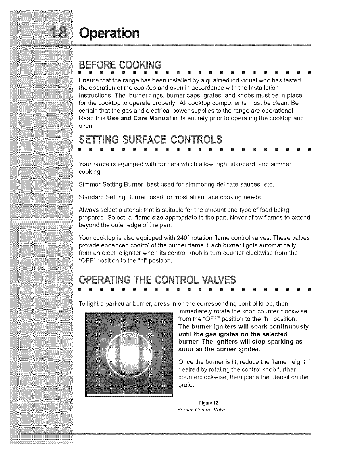
To light a particular burner, press in on the corresponding control knob, then
immediately rotate the knob counter clockwise
from the "OFF" position to the "hi" position.
The burner igniters will spark continuously
until the gas ignites on the selected
burner. The igniters will stop sparking as
soon as the burner ignites.
Once the burner is lit, reduce the flame height if
desired by rotating the control knob further
counterclockwise, then place the utensil on the
grate.
Figure 12
Burner Control Valve
Loading ...
Loading ...
Loading ...