Loading ...
Loading ...
Loading ...
Rinnai 26 ES_FT_OIM
FLUE INSTALLATION
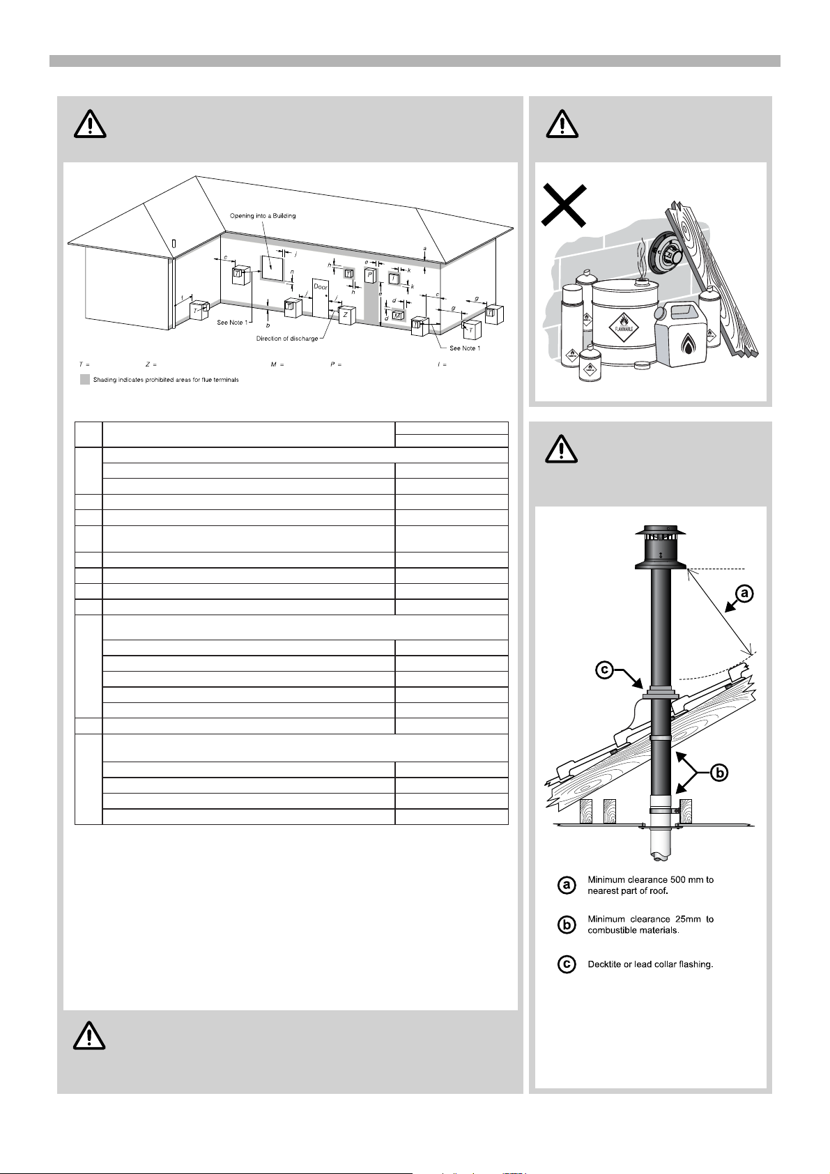
FLUE TERMINAL LOCATION
Ensue that the location of the flue terminal complies with
the requirements of AS/NZS 5601, Fig. 6.2 which is
reproduced in part below.
The flue terminal should
be positioned away from
flammable materials.
Horizontal terminal clearances (Extract AS/NZS 5601 Fig. 6.2)
Refer to the ‘Energysaver
Space Heater Co-Axial
Flue System Installation
Manual’ for full details
‘Vertical Terminal clearances (Extract
from the ‘Energysaver Space Heater Co-
Axial Flue System Installation Manual’)
AS/NZS 5601 was current at the time of printing this
manual, but may have been superseded. It is the installers
responsibility to ensure that the current version of this
standard is used.
WARN I N G
WARN I N G
Flue terminal Fan assisted flue appliance only Gas meter Electricity meter or fuse box Mechanical air inlet
Fan assisted
• Appliances up to 50 MJ/h input 200
• Appliances over 50 MJ/h input 300
b From the ground, above a balcony or other surface * 300
c Front a return wall or external corner * 300
d
From a gas meter (M) (see 5.11.5.9 for vent terminal location of regulator )
(see Table 6.6 for New Zealand requirements) 1000
e From an electricity meter or fuse box (P) † 500
f From a drain pipe or soil pipe 75
g Horizontally from any building structure* = or obstruction facing a terminal 500
h From any other flue terminal , cowl, or combustion air intake † 300
• Appliances up to 150 MJ/h input * 300
• Appliances over 150 MJ/h input up to 200 MJ/h input * 300
• Appliances over 200 MJ/h input up to 250 MJ/h input * 500
• Appliances over 250 MJ/h input * 1500
• All fan-assisted flue appliances , in the direction of discharge 1500
k From a mechanical air inlet, including a spa blower 1000
• Space heaters up to 50 MJ/h input 150
• Other appliances up to 50 MJ/h input 500
• Appliances over 50 MJ/h input and up to 150 MJ/h input 1000
• Appliances over 150 MJ/h input 1500
1Where dimensions c, j or k cannot be achieved an equivalent horizontal distance
measured diagonally from the nearest discharge point of the terminal to the opening
may be deemed by the Technical Regulator to comply.
2See Clause 6.9.4 for restrictions on a flue terminal under a covered area.
3See Figure J3 for clearances required from a flue terminal to an LP Gas cylinder.
A flue terminal is considered to be a source of ignition.
4
Ref. Item
a
Min. clearances (mm)
Below eaves, balconies and other projections:
j
Horizontally from an openable window, door, non-mechanical air inlet, or any other opening into a building
with the exception of sub-floor ventilation:
Vertically below an openable window, non-mechanical air inlet, or any other opening into a building with the
exception of sub-floor ventilation:
NOTES:
† - Prohibited area below electricity meter or fuse box extends to ground level.
EXTRACT OF FIGURE 6.2 (in-part)
* - unless appliance is certified for closer installation
For appliance snot addressed above acceptance should be obtained from the Technical Regulator.
n
I M PORT A N T
I M PORT A N T
Loading ...
Loading ...
Loading ...