Loading ...
Loading ...
Loading ...
Installation
1
To UPS
To UPS
A
B
7
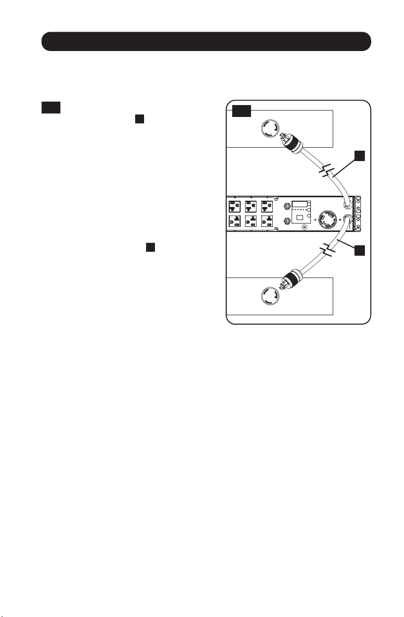
Connecting the PDU
Note: The PDU includes two input power cords: Primary and Secondary. They should be connected to two
separate AC power sources.
1
Connect PDU Input Plugs: Connect the
Primary input plug
A
to a preferred
source of grounded AC power (120V for
PDUMH30AT, PDUMNH30AT2 &
PDUMH30ATNET; 200-240V for
PDUMH30HVAT, PDUMNH30HVAT2,
PDUMH30HVATNET, PDUMH32HVAT,
PDUMNH32HVAT2 &
PDUMH32HVATNET), such as a
Tripp Lite SmartOnline
®
UPS System.
Under normal operating conditions, the
PDU will distribute AC power from the
Primary input source. Connect the
Secondary input plug
B
to an
alternative source of grounded AC
power (120V for PDUMH30AT,
PDUMNH30AT2 & PDUMH30ATNET;
200-240V for PDUMH30HVAT,
PDUMNH30HVAT2, PDUMH30HVATNET,
PDUMH32HVAT, PDUMNH32HVAT2 &
PDUMH32HVATNET), For proper ATS
(automatic transfer switch) function, do
not plug the Secondary input into the
same power source as the Primary
input. The PDU will distribute AC power
from the Secondary input only if the
Primary input becomes unavailable due
to an outage or power quality problem.
(See Configuration and Operation
section for more information about the
ATS function.)
Loading ...
Loading ...
Loading ...