Loading ...
Loading ...
Loading ...
AttachingTheSeat
Seat styles vary by tractor model and there are three
different styles available:
• Standard Adjustment
• Quick Adjustment &
• Knob Adjustment
Refer to Figure 3, Figure 4 and Figure 5 to identify your
tractor's seat style and follow applicable instructions
below.
NOTE: For shipping reasons, seats are either
fastened to the tractor seat's pivot bracket with a plastic
tie, or mounted backward to the pivot bracket. In either
case, free the seat form its shipping position and
remove the two hex screws (or knobs, on models so
equipped) from the bottom of seat before proceeding
with applicable instructions below.
Standard AdjustmentSeat
1. Position the shoulder screws (found on the base of
the seat) inside the slot openings in the seat pivot
bracket. Figure 3.
2. Slide the seat slightly rearward in the seat pivot
bracket, lining up the rear slots in the pivot bracket
with the remaining two holes inthe seat's base.
3. Select desired position for the seat, and secure with
the two hex screws removed earlier. See Figure 3.
QuickAdjustmentSeat
NOTE: If your seat was shipped mounted backwards
on the seat pivot bracket, pull out the tab found on the
seat stop and hold # open while sliding the seat off the
seat pivot bracket. See Figure 4.
1. Line up the plastic seat spacers with the slots in
seat pivot bracket.
2. Slide seat in until front seat spacer engages the
seat stop. See Figure 4.
WARNING: Before operating this machine,
make sure the seat is engaged in the seat
stop, stand behind the machine and pull back
on seat until fully engaged into stop.
KnobAdjustmentSeat
1. Position the shoulder screws (found on the base of
the seat) inside the slot openings in the seat pivot
bracket. Figure 5.
2. Slide the seat slightly rearward in the seat pivot
bracket, lining up the rear slots in the pivot bracket
with the remaining two holes inthe seat's base.
3. Select desired position for the seat, and secure with
the two knobs removed earlier. See Figure 5.
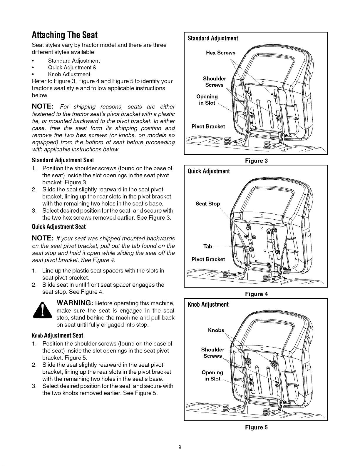
Standard Adjustment
Hex Screws
Shoulder
Screws
Opening
in Slot
Pivot Bracket
QuickAdjustment
Figure 3
Seat Stop
\
Tab--
Pivot Bracket
KnobAdjustment
Figure 4
Knobs
Shoulder
Screws
Opening
in Slot_
Figure 5
Loading ...
Loading ...
Loading ...