Loading ...
Loading ...
Loading ...
SECTION6: MAKINGADJUSTMENTS
,_ WARNING: Never attempt to make any
adjustments while the engine is running,
except where specified in the operator's
manual.
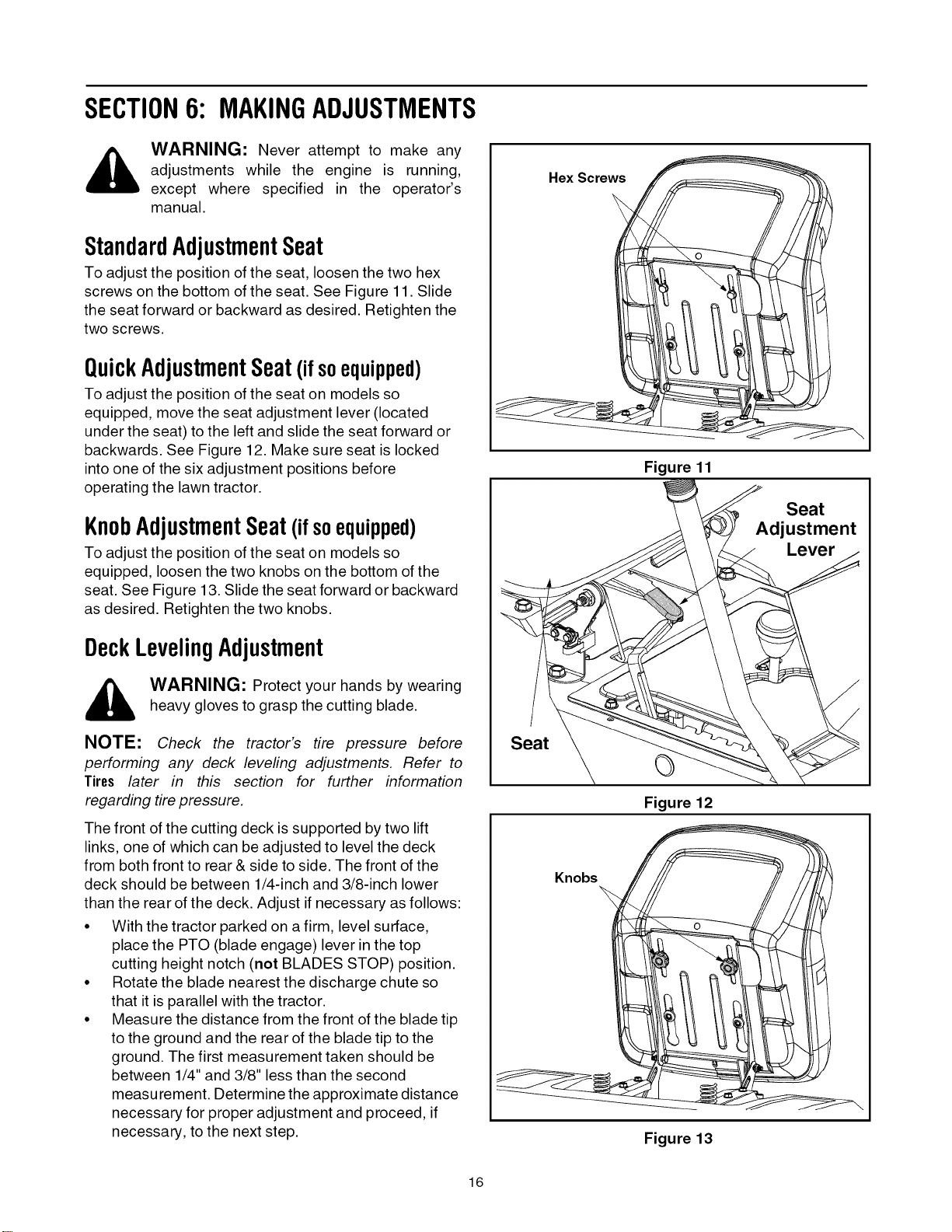
StandardAdjustmentSeat
To adjust the position of the seat, loosen the two hex
screws on the bottom of the seat. See Figure 11. Slide
the seat forward or backward as desired. Retighten the
two screws.
QuickAdjustmentSeat(ifsoequipped)
To adjust the position of the seat on models so
equipped, move the seat adjustment lever (located
under the seat) to the left and slide the seat forward or
backwards. See Figure 12. Make sure seat is locked
into one of the six adjustment positions before
operating the lawn tractor.
KnobAdjustmentSeat(if soequipped)
To adjust the position of the seat on models so
equipped, loosen the two knobs on the bottom of the
seat. See Figure 13. Slide the seat forward or backward
as desired. Retighten the two knobs.
DeckLevelingAdjustment
WARNING: Protect your hands by wearingheavy gloves to grasp the cutting blade.
NOTE: Check the tractor's tire pressure before
performing any deck leveling adjustments. Refer to
Tires later in this section for further information
regarding tire pressure.
The front of the cutting deck is supported by two lift
links, one of which can be adjusted to level the deck
from both front to rear & side to side. The front of the
deck should be between 1/4-inch and 3/8-inch lower
than the rear of the deck. Adjust if necessary as follows:
• With the tractor parked on a firm, level surface,
place the PTO (blade engage) lever in the top
cutting height notch (not BLADES STOP) position.
• Rotate the blade nearest the discharge chute so
that it is parallel with the tractor.
• Measure the distance from the front of the blade tip
to the ground and the rear of the blade tip to the
ground. The first measurement taken should be
between 1/4" and 3/8" less than the second
measurement. Determine the approximate distance
necessary for proper adjustment and proceed, if
necessary, to the next step.
Hex Screws
Figure 11
Seat
Adjustment
Lever
Seat
Q
Figure 12
Knobs
Figure 13
16
Loading ...
Loading ...
Loading ...