Loading ...
Loading ...
Loading ...
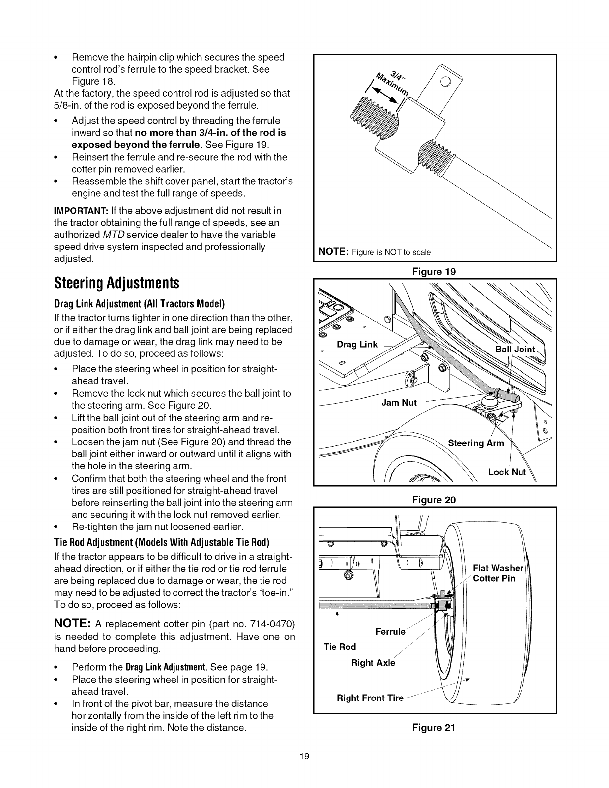
• Remove the hairpin clip which secures the speed
control rod's ferrule to the speed bracket. See
Figure 18.
At the factory, the speed control rod is adjusted so that
5/8-in. of the rod is exposed beyond the ferrule.
• Adjust the speed control by threading the ferrule
inward so that no more than 3/4-in. of the rod is
exposed beyond the ferrule. See Figure 19.
• Reinsert the ferrule and re-secure the rod with the
cotter pin removed earlier.
• Reassemble the shift cover panel, start the tractor's
engine and test the full range of speeds.
IMPORTANT: If the above adjustment did not result in
the tractor obtaining the full range of speeds, see an
authorized MTD service dealer to have the variable
speed drive system inspected and professionally
adjusted.
SteeringAdjustments
BragLink Adjustment(All Tractors Model)
If the tractor turns tighter in one direction than the other,
or if either the drag link and ball joint are being replaced
due to damage or wear, the drag link may need to be
adjusted. To do so, proceed as follows:
• Place the steering wheel in position for straight-
ahead travel.
• Remove the lock nut which secures the ball joint to
the steering arm. See Figure 20.
• Lift the ball joint out of the steering arm and re-
position both front tires for straight-ahead travel.
• Loosen the jam nut (See Figure 20) and thread the
ball joint either inward or outward until italigns with
the hole in the steering arm.
• Confirm that both the steering wheel and the front
tires are still positioned for straight-ahead travel
before reinserting the ball joint into the steering arm
and securing it with the lock nut removed earlier.
• Re-tighten the jam nut loosened earlier.
Tie RodAdjustment(ModelsWithAdjustableTie Rod)
If the tractor appears to be difficult to drive in a straight-
ahead direction, or if either the tie rod or tie rod ferrule
are being replaced due to damage or wear, the tie rod
may need to be adjusted to correct the tractor's "toe-in."
To do so, proceed as follows:
NOTE: A replacement cotter pin (part no. 714-0470)
is needed to complete this adjustment. Have one on
hand before proceeding.
• Perform the DragLinkAdjustment.See page 19.
• Place the steering wheel in position for straight-
ahead travel.
• In front of the pivot bar, measure the distance
horizontally from the inside of the left rim to the
inside of the right rim. Note the distance.
NOTE: Figure is NOT to scale
Drag Link
Figure 19
Steering Arm
Lock Nut
Figure 20
Flat Washe
/Cotter Pin
A Ferrule _
Tie Rod
Right Axle
Right Front Tire
Figure 21
19
Loading ...
Loading ...
Loading ...