Loading ...
Loading ...
Loading ...
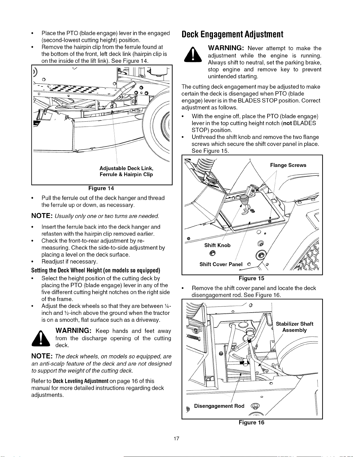
Place the PTO (blade engage) lever in the engaged
(second-lowest cutting height) position.
Remove the hairpin clip from the ferrule found at
the bottom of the front, left deck link (hairpin clip is
on the inside of the lift link). See Figure 14.
o
Adjustable Deck Link,
Ferrule & Hairpin Clip
Figure 14
Pull the ferrule out of the deck hanger and thread
the ferrule up or down, as necessary.
NOTE: Usually only one or two turns are needed.
• Insert the ferrule back into the deck hanger and
refasten with the hairpin clip removed earlier.
• Check the front-to-rear adjustment by re-
measuring. Check the side-to-side adjustment by
placing a level on the deck surface.
• Readjust if necessary.
Settingthe DeckWheelHeight(onmodelssoequipped)
• Select the height position of the cutting deck by
placing the PTO (blade engage) lever in any of the
five different cutting height notches on the right side
of the frame.
• Adjust the deck wheels so that they are between 1__
inch and Y2-inch above the ground when the tractor
is on a smooth, flat surface such as a driveway.
_, ARNING: Keep hands and feet away
from the discharge opening of the cutting
deck.
NOTE: The deck wheels, on models so equipped, are
an anti-scalp feature of the deck and are not designed
to support the weight of the cutting deck.
Refer to DeckLevelingAdjustmenton page 16 of this
manual for more detailed instructionsregarding deck
adjustments.
DeckEngagementAdjustment
_, WARNING: Never attempt to make the
adjustment while the engine is running.
Always shift to neutral, set the parking brake,
stop engine and remove key to prevent
unintended starting.
The cutting deck engagement may be adjusted to make
certain the deck is disengaged when PTO (blade
engage) lever is in the BLADES STOP position. Correct
adjustment as follows.
• With the engine off, place the PTO (blade engage)
lever in the top cutting height notch (not BLADES
STOP) position.
• Unthread the shift knob and remove the two flange
screws which secure the shift cover panel in place.
See Figure 15.
Flange Screws
Shift Knob /
/
/
Shift Cover Panel
Figure 15
Remove the shift cover panel and locate the deck
disengagement rod. See Figure 16.
//
Disengagement Rod (_
/_1 Stabilizer Shaft
Assembly
/
o
Figure 16
17
Loading ...
Loading ...
Loading ...