Loading ...
Loading ...
Loading ...
• Remove the belt guards (located over each outer
spindle pulley) by removing the self-tapping screws
which secure them in place. Refer Figure 32.
• Using a spring puller (MTD Part No. 732-0571 )or
other suitable tool, disconnect the extension spring
from the rear of the cutting deck belt. This will
relieve tension on the lower deck belt.
• Remove the lower deck belt from around the idler
pulleys, and the three spindle pulleys.
• Reassemble new belts, following instructions in
reverse order.
DriveBelts(Upper and Lower)
NOTE: The engine pufley must be removed from the
engine's crankshaft in order to change the tractor's
drive belts. Doing so requires an air/impact wrench.
It is recommended that both drive belts be changed at
the same time.
Place the PTO (blade engage) lever in the engaged
(all the way forward) position.
Unthread the shift knob and remove the two flange
screws which secure the shift cover panel in place.
Refer to Figure 15. Remove the shift cover panel.
NOTE: There is a small yeflow wire connected to a
spring switch on the underside of the shift cover panel.
Be careful not to damage it when removing the panel.
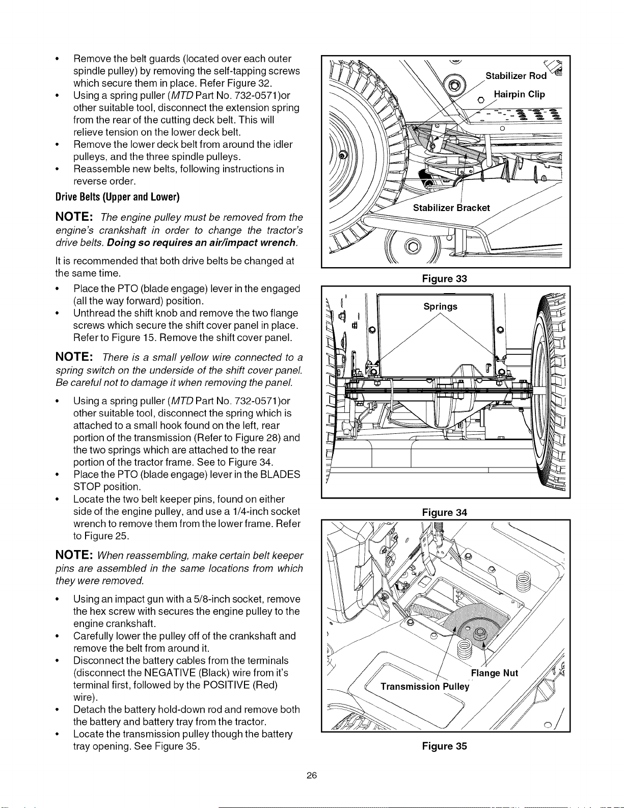
• Using a spring puller (MTD Part No. 732-0571 )or
other suitable tool, disconnect the spring which is
attached to a small hook found on the left, rear
portion of the transmission (Refer to Figure 28) and
the two springs which are attached to the rear
portion of the tractor frame. See to Figure 34.
• Place the PTO (blade engage) lever in the BLADES
STOP position.
• Locate the two belt keeper pins, found on either
side of the engine pulley, and use a 1/4-inch socket
wrench to remove them from the lower frame. Refer
to Figure 25.
NOTE: When reassembling, make certain belt keeper
pins are assembled in the same locations from which
they were removed.
• Using an impact gun with a 5/8-inch socket, remove
the hex screw with secures the engine pulley to the
engine crankshaft.
• Carefully lower the pulley off of the crankshaft and
remove the belt from around it.
• Disconnect the battery cables from the terminals
(disconnect the NEGATIVE (Black) wire from it's
terminal first, followed by the POSITIVE (Red)
wire).
• Detach the battery hold-down rod and remove both
the battery and battery tray from the tractor.
• Locate the transmission pulley though the battery
tray opening. See Figure 35.
Figure 33
Springs
Stabilizer Rod_
Hairpin Clip
0
Figure 34
/
Figure 35
26
Loading ...
Loading ...
Loading ...