Loading ...
Loading ...
Loading ...
• Carefully lower the rear portion of the deck to the
ground.
• Place the PTO (blade engage) lever in the BLADES
STOP position to raise the lift links up, and out of
the way.
• Carefully slide the deck from beneath the right side
of the lawn tractor
46-inch Decks
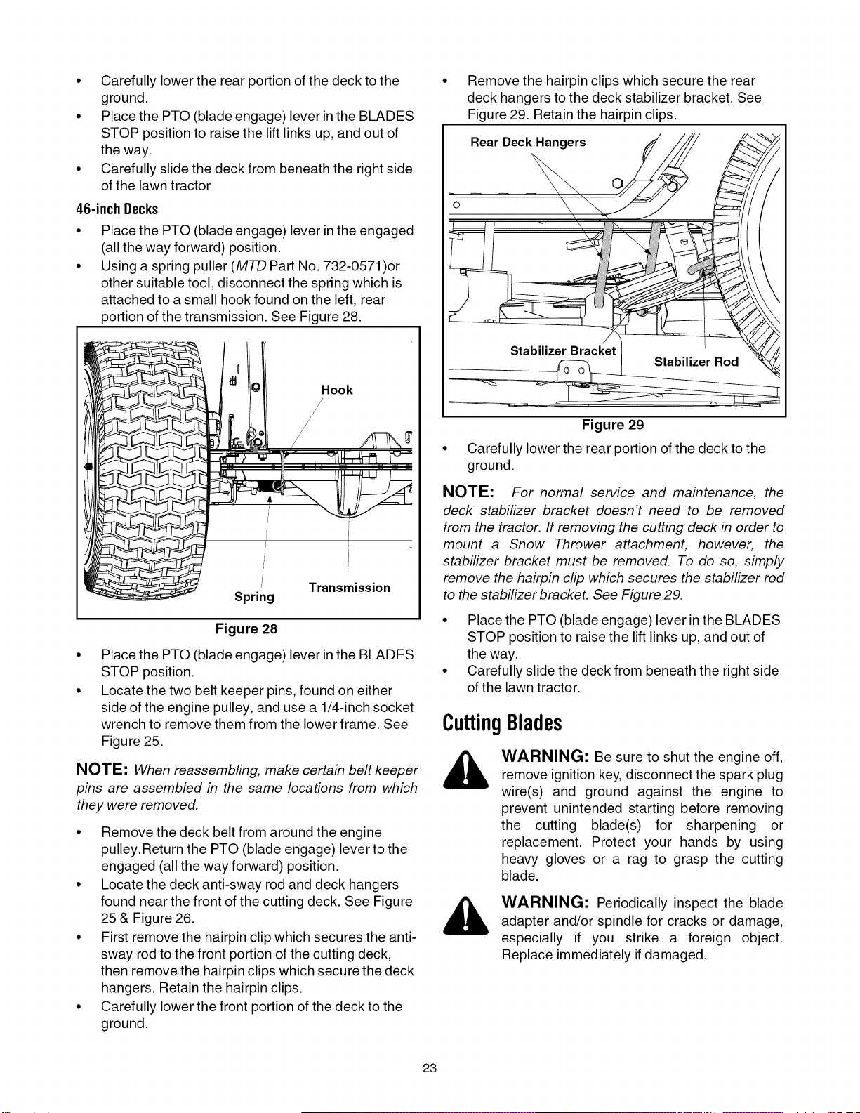
Place the PTO (blade engage) lever in the engaged
(all the way forward) position.
Using a spring puller (MTD Part No. 732-0571 )or
other suitable tool, disconnect the spring which is
attached to a small hook found on the left, rear
portion of the transmission. See Figure 28.
Hook
/
Spring Transmission
Figure 28
Place the PTO (blade engage) lever in the BLADES
STOP position.
Locate the two belt keeper pins, found on either
side of the engine pulley, and use a 1/4-inch socket
wrench to remove them from the lower frame. See
Figure 25.
NOTE: When reassembling, make certain belt keeper
pins are assembled in the same locations from which
they were removed.
• Remove the deck belt from around the engine
pulley.Return the PTO (blade engage) lever to the
engaged (all the way forward) position.
• Locate the deck anti-sway rod and deck hangers
found near the front of the cutting deck. See Figure
25 & Figure 26.
• First remove the hairpin clip which secures the anti-
sway rod to the front portion of the cutting deck,
then remove the hairpin clips which secure the deck
hangers. Retain the hairpin clips.
• Carefully lower the front portion of the deck to the
ground.
©
Remove the hairpin clips which secure the rear
deck hangers to the deck stabilizer bracket. See
Figure 29. Retain the hairpin clips.
Rear Deck Hangers
Stabilizer Bracket
Figure 29
Carefully lower the rear portion of the deck to the
ground.
NOTE: For normal service and maintenance, the
deck stabilizer bracket doesn't need to be removed
from the tractor. If removing the cutting deck in order to
mount a Snow Thrower attachment, however, the
stabilizer bracket must be removed. To do so, simply
remove the hairpin clip which secures the stabilizer rod
to the stabilizer bracket. See Figure 29.
• Place the PTO (blade engage) lever in the BLADES
STOP position to raise the lift links up, and out of
the way.
• Carefully slide the deck from beneath the right side
of the lawn tractor.
CuttingBlades
WARNING: Be sure to shut the engine off,
remove ignition key, disconnect the spark plug
wire(s) and ground against the engine to
prevent unintended starting before removing
the cutting blade(s) for sharpening or
replacement. Protect your hands by using
heavy gloves or a rag to grasp the cutting
blade.
WARNING: Periodically inspect the blade
adapter and/or spindle for cracks or damage,
especially if you strike a foreign object.
Replace immediately ifdamaged.
23
Loading ...
Loading ...
Loading ...