Loading ...
Loading ...
Loading ...
Input Volts (AC): ........... 230
Hertz (Cycles): ................ 60
Output Amperage: ........ 30 to 140
40 to 230
Rated Input Amps: ............... 50
Short Circuit Input Amps: ......... 66
SPECIFICATIONS
Fuse or Circuit
Breaker Required: ......... 50 Amps
Arc Voltage: ............... 25
KVA: .................... 108
KW: ........................... 7 1
Max Open Circuit
Output Volts .......... 80
Power Factor ........... 66%
Duty Cycle: ........ 20 to 100%
Electrode Capacity: 1/16" to 3/16"
UNPACKING AND CHECKUNG CONTENTS
SET-UP INSTRUCTIONS
This Craftsman welder is shipped complete in one carton
In order to facilitate packaging, certain items have been
removed at the factory and must be assembled when
received by the purchaser Remove all items from the
carton and identify item as shown in the exploded view
illustration These "Loose Parts" should be accounted for
before discarding any packaging material.
3 4
LOOSE PARTS LIST
Key
No. Part Name
O.ty.
i
1 WeldingHelmet(Partially assembled) ..........
2 Helmet bandassembly(Not Assembled) ........
3 Electrodecableassembly .........................
4 LoosePartsBag- Containingthe following items:
Electrode Holder .....................................
t
1
1
I
1
Work Clamp ........................................... 1
Screw,Hex.-Hd.,1/4-20 x 3/4 in............... 1
Nut, Hex., 1/4-20 ........................... 1
Washer,Flat 17/64 in............................... 1
Loci{washer,1/4 in 1
ASSEMBLY
TOOLS NEEDED
,,lOinchwrenchScrewdriver(medium)
ATTACHING ELECTRODE HOLDER ............. ....
TO ELECTRODE CABLE
I. Grasp the electrode holder and locate the slotted head,
handle locking screw near the mid-point of the insulating
handle Loosen this screw approximately two turns, or
until the handle can be slipped off the electrode bolder..
2 Do not remove this screw completely. Slide tile handle
off electrode holder and insert end of electrode cable
assembly through the handle.
The electrode cable is the one with insulation stripped
from one end
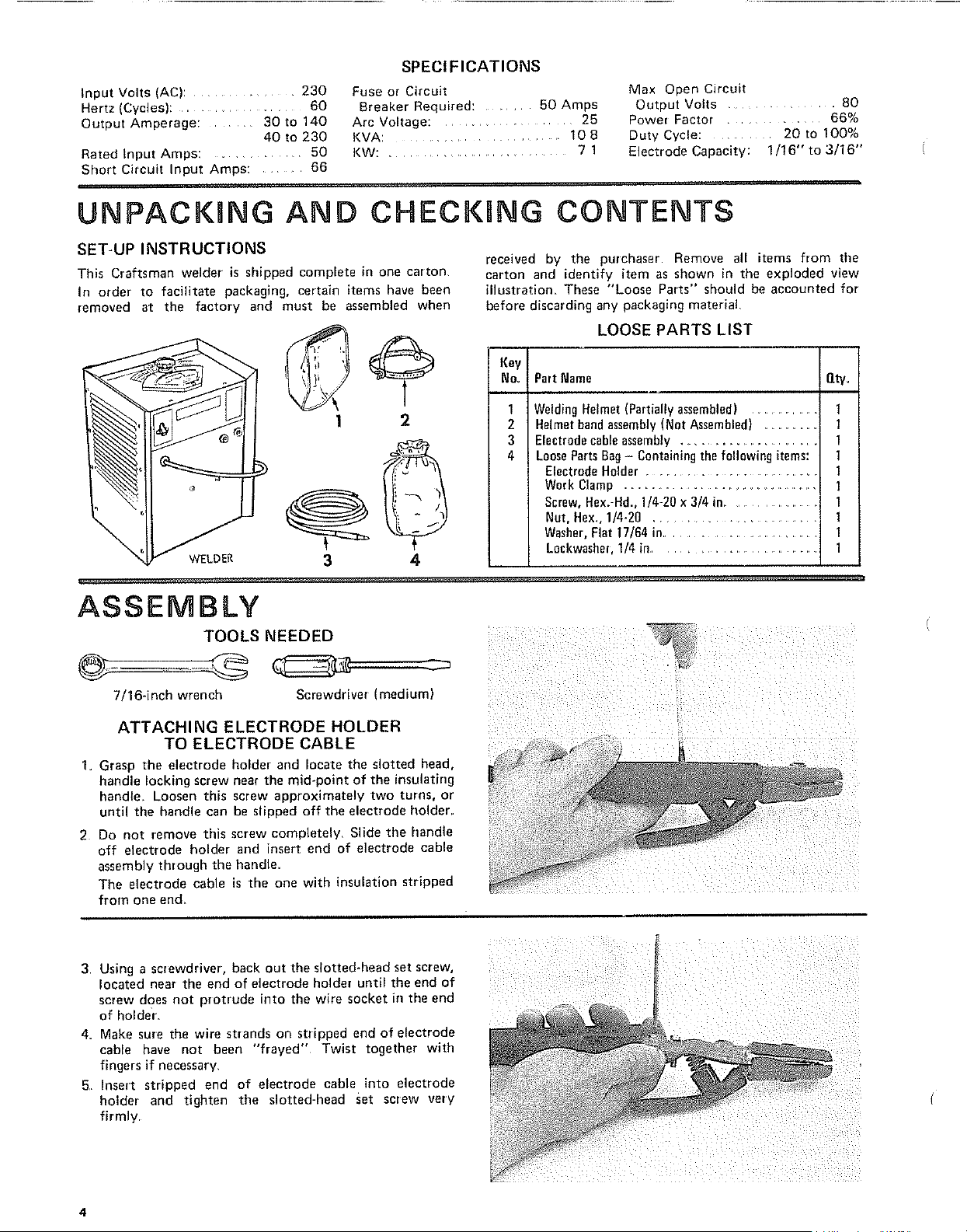
3 Using a screwdriver, back out the slotted-head set screw,
located near the end of electrode holder until the end of
screw does not protrude into the wire socket in the end
of holder
4. Make sure the wire strands on stripped end of electrode
cable have not been "frayed" Twist together with
fingers if necessary.
5 Insert stripped end of electrode cable into electrode
holder and tighten the slotted-head set screw very
firmly
4
Loading ...
Loading ...
Loading ...