Loading ...
Loading ...
Loading ...
TRUMB KHOB
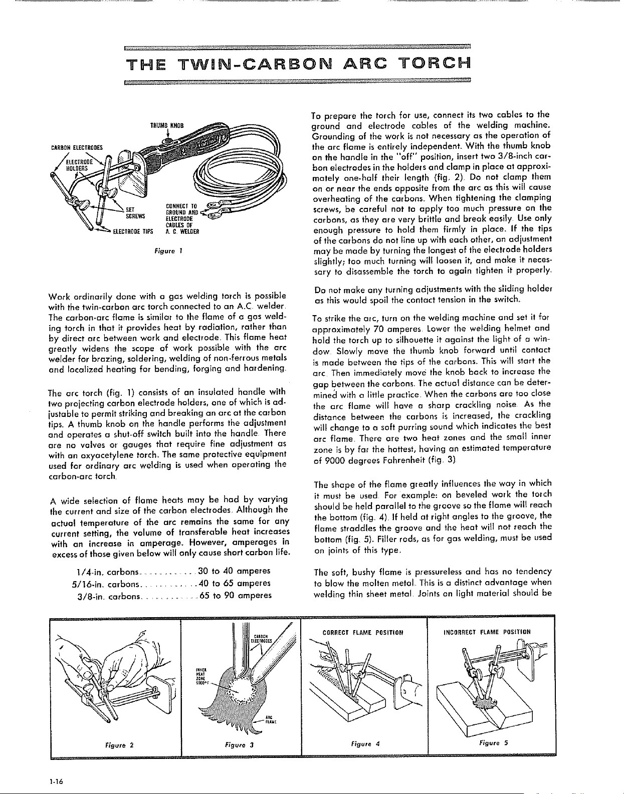
CARBORELECTRODES
CORRECTTO
GROUNDAND:
SCREWS ELECTRODE
CABLESOF
ELECTRODETiPS A C WELDER
Figure 1
Work ordinarily done with a gas weldlng torch is possible
with the twln-carbon arc torch connected to an A.C welder,
The carbon-arc flame is similar to the flame of a gas weld-
ing torch in that it provides heat by radiation, rather than
by direct arc between work and electrode, This flame heat
greatly widens the scope of work possible with the arc
welder for brazing, soldering, welding of non.ferrous metals
and localized heaffng for bending, forging and hardening,
The arc torch (fig. 1) consists of an insulated handle wlth
two projecting carbon electrode holders, one of which isad-
justable to permit striking and breaking an arc at the carbon
tips. A thumb knob on the handle performs the adjustment
and operates a shut-off switch built into the handle There
are no valves or gouges that require fine adjustment as
with an oxyacetylene torch. The same protective equipment
used for ordinary arc welding is used when operating the
carbon-arc torch.
A wide selection of flame heats may be had by varying
the current and size of the carbon electrodes, Although the
actual temperature of the arc remains the same for any
current setting, the volume of transferable heat increases
with an increase in amperage° However, amperages in
excess of those given below will only cause short carbon life.
1/4-ira carbons ............ 30 to 40 amperes
5/16-im carbons .............. 40 to 65 amperes
3/8-im carbons ............... 65 to 90 amperes
To prepare the torch for use, connect its two cables to the
ground and electrode cables of the welding machine.
Grounding of the work is not necessary as the operation of
the arc flame is entirely independenL With the thumb knob
on the handle in the "off" position, insert two 3/8-inch car-
bon electrodes in the holders and clamp in place at approxi-
mately one-half their length (fig, 2) Do not clamp them
on or near the ends opposite from the arc as this will cause
overheating of the carbons When tightening the clamping
screws, be careful not to apply too much pressure on the
carbons, as they are very brittle and break easily Use only
enough pressure to hold them firmly in place. If the tips
of the carbons do not llne up with each other, an adjustment
may be made by turning the longest of the electrode holders
slightly; too much turning will loosen it, and make it neces-
sary to disassemble the torch to again tighten it properly,
Do not make any turning adlustments wl h the s,id ng holder
as this would spoil the contact tension in the switch.
To strike the arc, turn on the welding machine and set it for
approximately 70 amperes Lower the welding helmet and
hold the torch up to silhouette it against the light of a win-
dow Slowly move the thumb knob forward until contact
is made between the tips of the carbons. This will start the
arc Then immediately move the knob back to increase the
gap between the carbons The actual distance can be deter-
minecl with a little practice When the carbons are too close
the arc flame will have a sharp crackling noise As the
distance between the carbons is increased, the crackling
will change to o soft purring sound which indicates the best
arc flame There are two heat zones and the small inner
zone isby far the hottest, having an estimated temperature
of 9000 degrees Fahrenheit (fig, 3)
The shape of the flame gleatly influences the way in which
it must be used For example: on beveled work the torch
should be held parallel to the groove so the flame will reach
the bottom (fig 4), If held at right angles to the groove, the
flame straddles the groove and the heat will not reach the
bottom (fig 5). Filler rods, as for gas welding, must be used
on joints of this type.
The soft, bushy flame is pressureless and has no tendency
to blow the mohen metal This is a distinct advantage when
welding thin sheet metal Joints on light material should be
Figure 2 Figure 3
CORRECT FLAME POSITION
Figure 4
INCORRECT FLAME POSITION
Figure 5
,r.,,,,,
1-16
Loading ...
Loading ...
Loading ...