Loading ...
Loading ...
Loading ...
ASSEMBLY
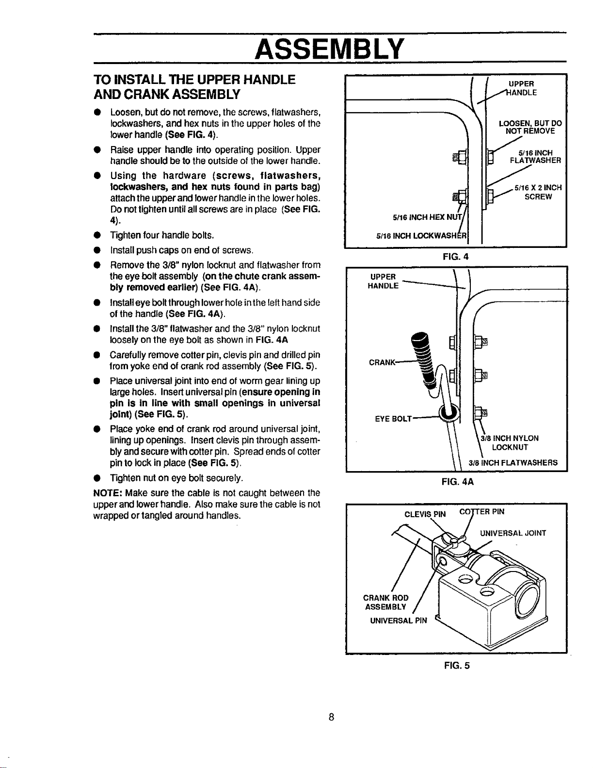
TO INSTALL THE UPPER HANDLE
AND CRANK ASSEMBLY
• Loosen, but do notremove, the screws, flatwashers,
lockwashers, and hex nuts in the upper holes of the
lower handle (See FIG. 4).
• Raise upper handle into operating position. Upper
handle should be to the outside of the lower handle.
• Using the hardware (screws, flatwashers,
lockwashers, and hex nuts found in parts bag)
attachtheupperand lowerhandle inthe lowerholes.
Do nottighten untilall screwsare inplace (See FIG,
4).
• Tightenfour handle bolts.
• Install pushcaps on end of screws.
• Remove the 3/8" nylon Iocknutand flatwasher from
theeye bolt assembly (on the chute crank assem-
bly removed earlier) (See FIG. 4A).
• Install eye bolt through lowerhole inthe Ietthand side
of the handle (See FIG. 4A).
• Install the 3/8" flatwasherand the 3/8" nylon Iocknut
loosely on the eye bolt as shown in FIG. 4A
• Carefully remove cotter pin, clevis pin and drilled pin
from yoke end of crank rod assembly (See FIG. 5).
• Place universal joint into end of worm gear lining up
large holes. Insert universal pin (ensure opening in
pen is in line with small openings in universal
joint) (See FIG. 5).
• Place yoke end of crank rod around universaljoint,
liningupopenings. Insert clevis pinthroughassem-
blyand securewithcotter pin. Spread endsofcotter
pinto lockin place (See FIG. 5).
• Tighten nuton eye bolt securely.
NOTE: Make sure the cable is not caught between the
upperand lowerhandle. Also make sure the cable isnot
wrapped ortangled aroundhandles.
5!16 INCH HEX NUT/
/
5116 INCH LOCKWASHE$
FIG. 4
LOOSEN,BUTDO
NOT REMOVE
/
5/16 INCH
FLATWASHER
'/_5tl 6 X 2 INCH
SCREW
UPPER
HANDLE "_
f
/,f
3t8 INCH NYLON
LOCKNUT
318INCH
FIG. 4A
CLEVIS PiN
PIN
UNIVERSAL JOINT
CRANK ROD
ASSEMBLY
UNIVERSAL PIN
FIG. 5
8
Loading ...
Loading ...
Loading ...