IMPORTANT MANUAL DO NOT THROW AWAY
S AURS
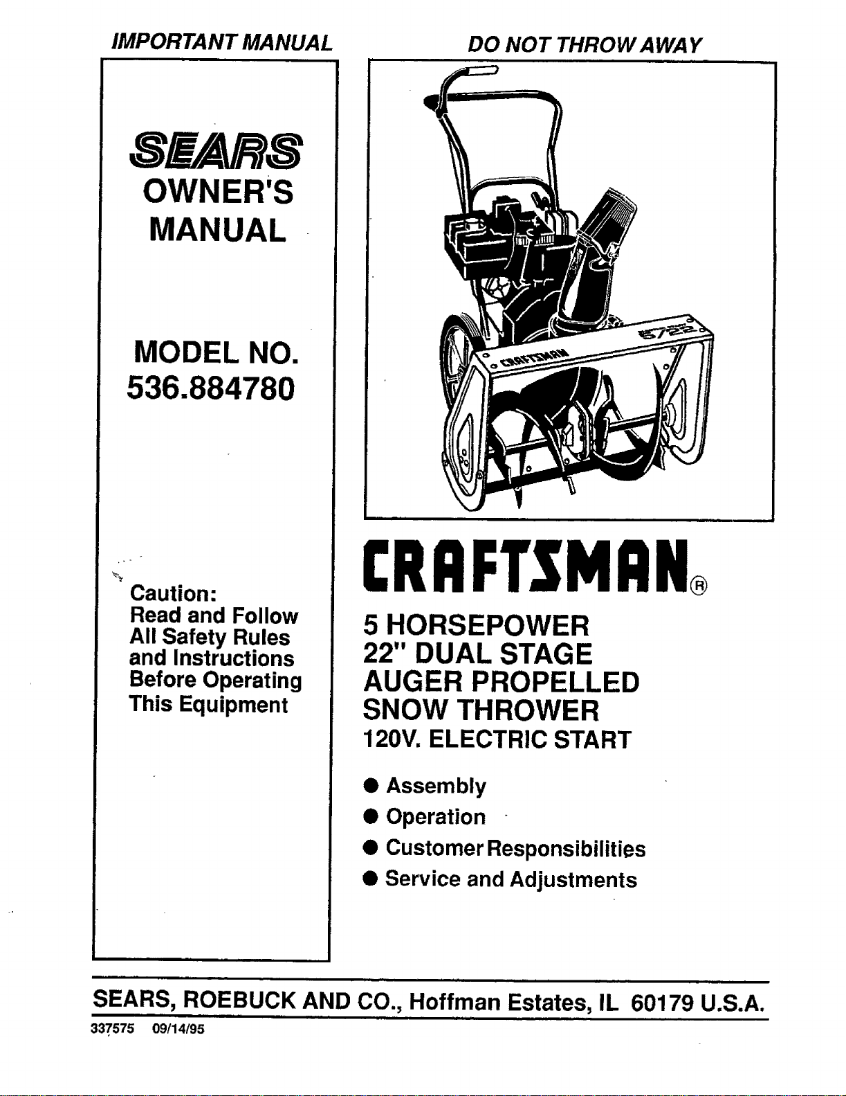
OWNER'S
MANUAL
MODEL NO.
536.884780
Caution:
Read and Follow
All Safety Rules
and Instructions
Before Operating
This Equipment
CRRFT.SMRN
5 HORSEPOWER
22" DUAL STAGE
AUGER PROPELLED
SNOW THROWER
120V. ELECTRIC START
• Assembly
• Operation
• Customer Responsibilities
• Service and Adjustments
nrll
SEARS, ROEBUCK AND CO., Hoffman Estates, IL 60179 U.S.A.
337575 09/14/95
SAFETY RULES
,_ CAUTION: ALWAYS DISCONNECT SPARK PLUG WIRE AND ,_
PLACE WIRE WHERE IT CANNOT CONTACT SPARK PLUG
TO PREVENT ACCIDENTAL STARTING WHEN SETTING-UP,
TRANSPORTING, ADJUSTING OR MAKING REPAIRS.
IMPORTANT
SAFETY STANDARDS REQUIRE OPERATOR PRESENCE CONTROLS TO MINIMIZE THE
RISK OF INJURY. YOUR SNOW THROWER IS EQUIPPED WITH SUCH CONTROLS. DO NOT
ATTEMPT TO DEFEAT THE FUNCTION OF THE OPERATOR PRESENCE CONTROL UNDER
ANY CIRCUMSTANCES.
TRAINING
1. Read the operator's manual carefully. Be
thoroughly familiar with the controls and the
proper use of the snow thrower. Know how to
stop the snow thrower and disengage the
controls quickly.
2. Never allow children to operate the snow thrower
and keep them away while it is operating. Never
allow adults to operate the snow thrower without
proper instruction. Do not carry passengers.
3. Keep the area o! operation clear of all persons,
particularly small children, and pets.
4. Exercise caution to avoid slipping or falling,
especially when operating in reverse.
PREPARATION
1. Thoroughly inspect the area where the snow
thrower is to be used and remove all doormats,
sleds, boards, wires, and other foreign objects.
2. Disengage all clutches and shift into neutral
before starting the engine (motor).
3. Do not operate the snow thrower without wearing
adequate winter outer garments. Wear footwear
that will improve footing on slippery surfaces.
4. Handle fuel with care; it is highly flammable.
(a) Use an approved fuel container.
(b) Never remove fuel tank cap or add fuel to a
runningengineor hot engine.
(c) Fill fuel tank outdoors with extreme care.
Never fil!fuel tank indoors.
.
(d) Replace fuel tank cap securely and wipe up
spilled fuel.
(e) Never store fuel or snow thrower'with fuel in
the tank inside of a building where fumes'may
reach an open flame or spark.
(f) Check fuel supply before each use, allowing
space for expansion as the heat of the engine
(motor) and/or sun can cause fuel to expand.
Use extension cords and receptacles as specifie_l
by the manufacturer for all snow throwers with.
electric drive motors or electric starting motors.
6. Adjust the snow thrower height to clear gravel or
crushed rock surfaces.
7. Never attempt to make any adjustments while the
engine (motor) is running (except when
specifically recommended by the manufacturer).
8. Let engine (motor) and snow thrower adjust to
outdoor temperatures before starting to clear
snow.
9. Always wear safety glasses or eye shields during
operation or while performing an adjustment or
repair to protect eyes from foreign objects that
may be thrown from the snow thrower.
OPERATION
1. Do not put hands or feet near or under rotating
parts. Keep clear of the discharge open=ng at all
times.
2. Exercise extreme caution when operating on or
crossing gravel drives, walks, or roads. Stay aler_
for hidden hazards or traffic.
.
.
After striking a foreign object, stop the engine
(motor), remove the wire from the spark plug,
disconnect the cord on electric motors,
thoroughly inspect the snow thrower for any
damage, and repair the damage before restarting
and operating the snow thrower.
If the snow thrower shoutd start to vibrate
abnormally, stop the (motor) and check
immediately for the cause. Vibration =sgenerally
a warning of trouble.
5. Stop the engine (motor) whenever you leave the
operating position, before unclogging the auger/
impeller housing or discharge guide, and when
making any repairs, adjustments, or inspections.
6. When cleaning, repairing, or respecting, make
certain the auger/impeller and all moving parts
have stopped. Disconnect the spark plug wire
and keep the wire away from the plug to prevent
accidental starting.
7. Take all possible precautions when leaving the
snow thrower unattended. Disengage the auger/
impeller, shift to neutral, stop engine, and
remove key.
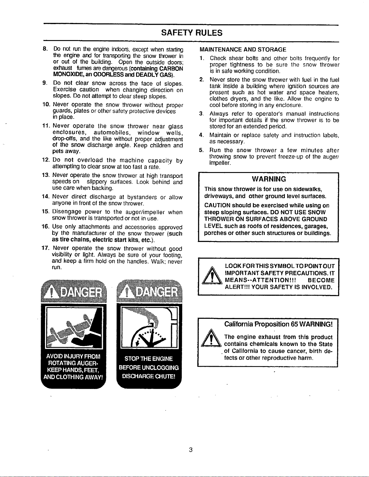
SAFETY RULES
MAINTENANCE AND STORAGE
8. Do not run the engine indoors,except when starting
the engine and for transporting the snow thrower in
or out of the building. Open the outside doors;
exhaust fumes are dangerous (containing CARBON
MONOXIDE,an ODORLESS and DEADLY GAS).
9• Do not clear snow across the face of slopes.
Exercise caution when changing direction on
slopes. Do not attempt to clear steep slopes.
10. Never operate the snow thrower without proper
guards, plates or other safety protective devices
in place.
11. Never operate the snow thrower near glass
enclosures, automobiles, window wells,
drop-oils, and the like without proper adjustment
of the snow discharge angle, Keep children and
pets away.
12. Do not overload the machine capacity by
attempting to clear snow at too fast a rate.
13. Never operate the snow thrower at high transport
speeds on slippery surfaces. Look behind and
use care when backing•
14. Never direct discharge at bystanders or allow
anyone in front of the snow thrower.
15. Disengage power to the auger/impeller when
snow thrower is transported or not in use.
16. Use only attachments and accessories approved
by the manufacturer of the snow thrower (such
as tire chains, electric start kits, etc.).
17. Never operate the snow thrower without good
visibilityor light. Always be sure of your footing,
and keep a firm hold on the handles. Walk; never
run.
1. Check shear bolts and other bolts frequentty for
proper tightness to be sure the snow thrower
is in safe working condition.
2. Never store the snow thrower with fuel in the fuel
tank inside a building where ignition sources are
present such as hot water and space heaters,
clothes dryers, and the like. Allow the engine to
cooi before storing in any enclosure.
3_ Always refer to operator's manual instructions
for important details if the snow thrower is to be
stored for an extended period.
4. Maintain or replace safety and instructionlabels,
as necessary.
5. Run the snow thrower a few minutes after
throwing snow to prevent freeze-up of the auger/
impeller.
WARNING
This snow thrower is for use on sidewalks,
driveways, and other ground level surfaces.
CAUTION should be exercised while using on
steep sloping surfaces. DO NOT USE SNOW
THROWER ON SURFACES ABOVE GROUND
LEVEL such as roofs of residences, garages,
porches or other such structures or buildings.
LOOK FOR THIS SYMBOL TO POINTOUT
iMPORTANT SAFETY PRECAUTIONS. tT
MEANS--ATTENTION!!! BECOME
ALERT!!7 YOUR SAFETY IS INVOLVED.
California Proposition 65WARNING!
The engine exhaust from this product
contains chemicals known to the State
• of California to cause cancer, birth de-
fects or other reproductive harm.
CONGRATULATIONSonyour purchase of a SEARS
Craftsman Snow Thrower. It has been designed, engi-
neered and manufactured to give you the best possible
dependabilityand performance.
Should you experience any problem you cannot easily
remedy, please contact your nearest SEARS Service
CentedDepartment. SEARS hascompetent, weU-trained
technicians andthe proper toolsto service or repair this
unit.
Please read and retain this manual. The instructions will
enable youto assemble and maintain your snow thrower
properly. Always observe the "SAFETY RULES."
MODEL
NUMBER 536.884780
SERIAL
NUMBER
DATE OF
PURCHASE
THE MODEL AND SERIAL NUMBERS WILL BE
FOUND ON A DECAL ATTACHED TO THE REAR
OF THE SNOW THROWER HOUSING.
YOU SHOULD RECORD BOTH SERIAL NUMBER
AND DATE OF PURCHASE AND KEEP INA SAFE
PLACE FOR FUTURE REFERENCE.
PRODUCT SPECIFICATIONS
HORSE POWER: 5 hp
DISPLACEMENT: 12.04
cu. in.
GASOLINE CAPACITY:
2 quarts
Unleaded
OIL (21 oz. Capacity): SAE 5W-30
SPARK PLUG : Champion
(GAP .030 in.) RJ19LM
i
VALVE CLEARANCE: Intake: .010 In,
Exhaust: .010 In.
MAINTENANCE AGREEMENT
A SEARS MaintenanceAgreement isavailable onthis
product.Contact yournearestSEARS Store for details.
CUSTOMER RESPONSIBILITIES
• Read and observe the safety rules.
• Followa regular schedule in maintaining,caring for and usingyour snow thrower.
• Followthe instructionsunder "Customer Responsibilities" and "Storage" sectionsofthis owner's manual.
TWO YEAR LIMITED WARRANTY ON CRAFTSMAN
SNOW THROWER
For twoyears from the date of purchase, when this Craftsman Snow Thrower is maintained, lubricated and tuned-
up according to the instructions in the owner's manual, SEARS will repair, free of charge, any defect in material
and workmanship.
If this Craftsman Snow Thrower isused for commercial or rental purposes, this warranty applies for only 90 days
from the date of purchase.
This warranty does not cover the following:
• Expendable items which become wornduring normal use, such as spark plugs, drive belts and shear pins.
• Repairs necessary because of operator abuse or negligence, including bent crankshafts and the failure to
maintain the equipment according to the instructions contained inthe owner'smanual.
WARRANTY SERVICE IS AVAILABLE BY RETURNING THE CRAFTSMAN SNOW THROWER TO THE
NEAREST SEARS SERVICE CENTER/DEPARTMENT iN THE UNITED STATES. THIS WARRANTY APPLIES
ONLY WHILE THIS PRODUCT tS IN USE IN THE UNITED STATES.
This warranty gives you specific legal rights, and you may also have other rights which may vary from state to state.
SEARS, ROEBUCK AND CO. Department D/817WA, Hoffman Estates, IL 60179
4
im=l ii i
TABLE OF CONTENTS
SAFETY RULES ........................................ 2,3
PRODUCT SPECIFICATIONS ...................... 4
CUSTOMER RESPONSIBILITIES ..... 4,15-16
WARRANTY .................................................. 4
TABLE OF CONTENTS. ............................... 5
INDEX ........................................................... 5
ASSEMBLY .......................................... •...... 6-9
OPERATION .......................................... t 0-14
SERVICE AND ADJUSTMENTS ........... ! 7-20
STORAGE ................................................... 2t
TROUBLE SHOOTING ............................... 22
REPAIR PARTS (SNOW THROWER)...23-31
REPAIR PARTS (ENGINE) .................... 32-35
PARTS ORDERING/SERVICE ................... 36
A
Assembly:
Cables ............................................. 7
Check list ......................................... 9
Crank Assemb[y .............................. 8
Snow Chute ..................................... 9
Tools for Assembly .......................... 6
Unpacking ........................................ 7
C
Crank:
Assembly ......................................... 8
Operation ....................................... ! 1
Customer Rssponsibilities....4,15-16
Agreement ....................................... 4
Auger Shaft ................................... 16
Engine ........................................... 16
General Recommendations .......... I5
Deflector, Snow Chute ..................... 11
E
Engine:
Control......................... lO, 11, 13, 14
Oil Cap ..................................... 12, 16
Oil Change ..................................... 16
Oil Level ................................... 12, 16
Oil Type ............................... 4, 12, 16
Storage .......................................... 21
F
Fuel, Type .............................. 4, 12, 16
Fuel, Storage .............................. 12, 21
H
Handle, Upper and Lower .............. 7, 8
Hex Shaft ......................................... 16
INDEX
I
Ignition, Key.......................... I 0, ! 1, 13
L
Levers:
Auger Drive Clutch ............................
............;................ 7, 9, 10, 11, !2, 17
Choke .......................... 10, 11, 13, 14
Throttle Control............ 10, t 1, 13, 14
Lubrication:
Auger Shaft .................................... 16
Axles .............................................. 16
Chart .............................................. 15
Engine ............................... 12, 16, 21
o
Oil:
Engine ................................. 4, 12, 16
Extreme Cold Weather ............. 13,18
Storage .......................................... 26
Type ..................................... 4, 13, 18
Operation:
Engine Controls............ 10, 11, 13,14
Operating Snow Thrower ......... 10-12
Operating Tips ............................... t4
Starting the Engine:
Recoil Start............................ 13, 14
Electric Start ................................ 13
Primer Button .................. 10, 11, 13,14
R
RepaidReplacement Parts .......... 23-31
S
Safety Rules .................................. 2, 3
Service and Adjustments:
Auger Shear Bolt........................... 19
Belt .......................................... 17, 18
Belt Guide ...................................... 18
Belt Replacements ........................ 18
Cables ................................... 7, 9, 17
Carburetor ............................... 19, 21
Spark Plug ............................... 20, 21
Specifications .................................. 4
Stopping the Engine ..................... 13
Stopping the Snow Thrower .......... 11
Shipping Carton .......................... 6, 7
Storage .......................................... 21
Symbols ........................................ 11
W
Warranty ............................................ 4
5
CONTENTS OF HARDWARE PACK
i
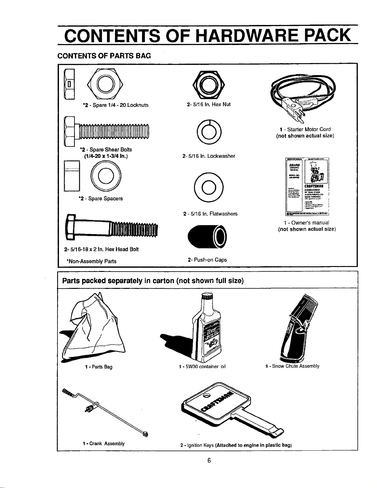
CONTENTS OF PARTS BAG
*2 - Spare 1/4 -20 Locknuts 2- 5/16 In. Hex Nut
*2 - Spare Shear Botts
(1/4-20 x 1-3/4 in.)
*2 - Spare Spacers
t.i
2- 5/16-18 x 2 In. Hex Head Bolt
2- 5/16 In. Lockwasher
2 - 5/16 In. Flatwashers
*Non-Assembly Parts 2- Push-on Caps
Parts packed separately in carton (not shown full size)
1 - Starter Motor Cord
(not shown actual size)
_u_ _
_L r,o.
FRR_IU411N
_ = h'amE_w
1 - Owner's manual
(not shown actual size)
1- PartsBag
1 - 5W30 container orl 1 - Snow Chute Assembly
1- CrankAssembly
2 - ignition Keys (Atlached to engine in plastic bag)
ASSEMBLY
TOOLS REQUIRED FOR ASSEMBLY
1 - Knife(to cut carton and plastic ties)
2 - 112inch wrenches (or adjustable wrenches)
2 - 9/16 inchwrenches (or adjustable wrenches)
2 - 3/4 inchwrenches (or adjustable wrenches)
1 - Pliers (to spread cotter pin)
1- Screwdriver
1 - Measuring Tape or Ruler
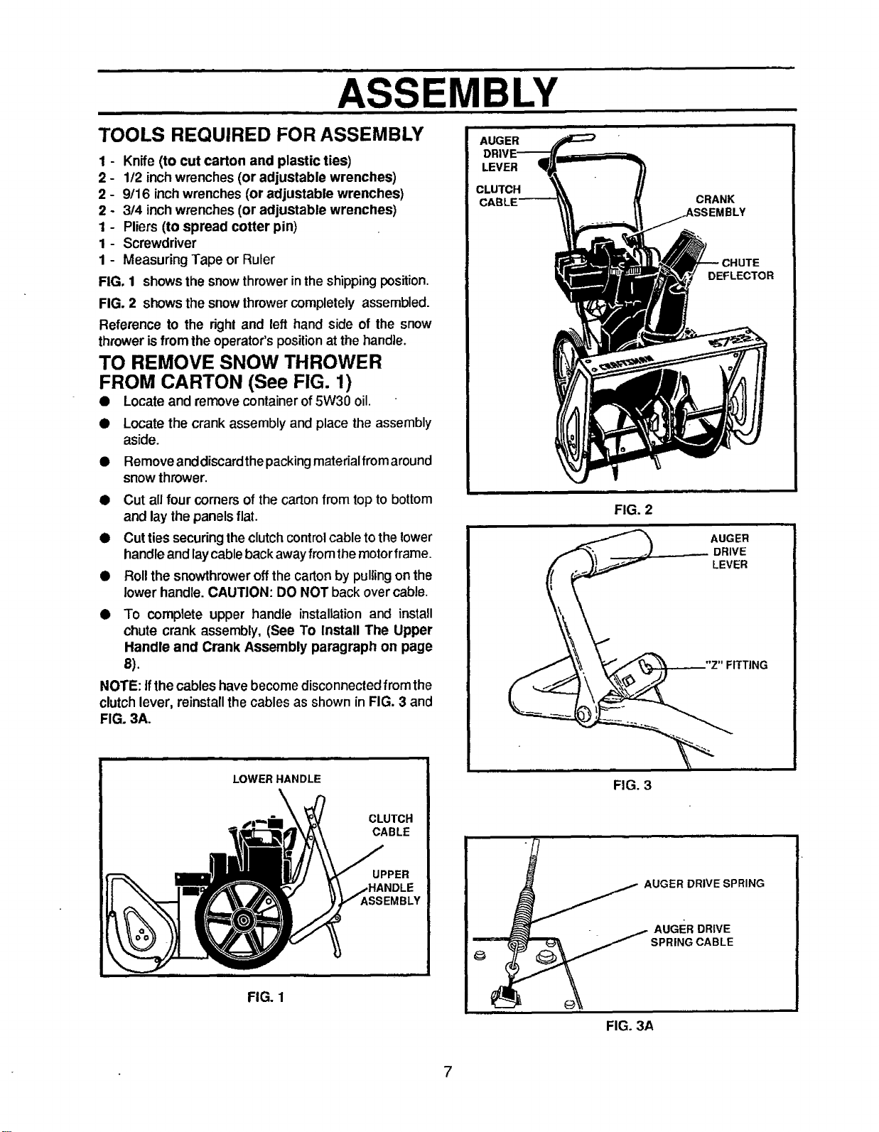
FIG. 1 shows the snowthrowerin theshippingposition.
FIG. 2 shows the snowthrowercompletely assembled.
Reference to the right and left hand side of the snow
throwerisfrom the operator'spositionat the handle.
TO REMOVE SNOW THROWER
FROM CARTON (See FIG. 1)
• Locate and remove container of 5W30 oil.
• Locate the crank assembly and place the assembly
aside.
• Remove anddiscardthepacking materialfromaround
snow thrower.
• Cut all four comers ofthe carton from top to bottom
and lay the panelsflat.
• Cut ties securing the clutch control cable to the lower
handle and laycable back away from the motor frame.
• Roll the snowthrower off the carton by pulling on the
lower handle. CAUTION: DO NOT back over cable.
• To complete upper handle installation and install
chute crank assembly, (See To Install The Upper
Handle and Crank Assembly paragraph on page
8).
NOTE: if the cables havebecomedisconnectedfrom the
clutchlever, reinstallthe cables as shown in FIG. 3 and
FIG. 3A.
AUGER
LEVER
CLUTCH
FIG. 2
CRANK
}LY
DEFLECTOR
AUGER
DRIVE
LEVER
FITTING
LOWER HANDLE
FIG. 1
CLUTCH
CABLE
UPPER
SSEMBLY
FIG. 3
AUGER DRIVE SPRING
FIG. 3A
7
ASSEMBLY
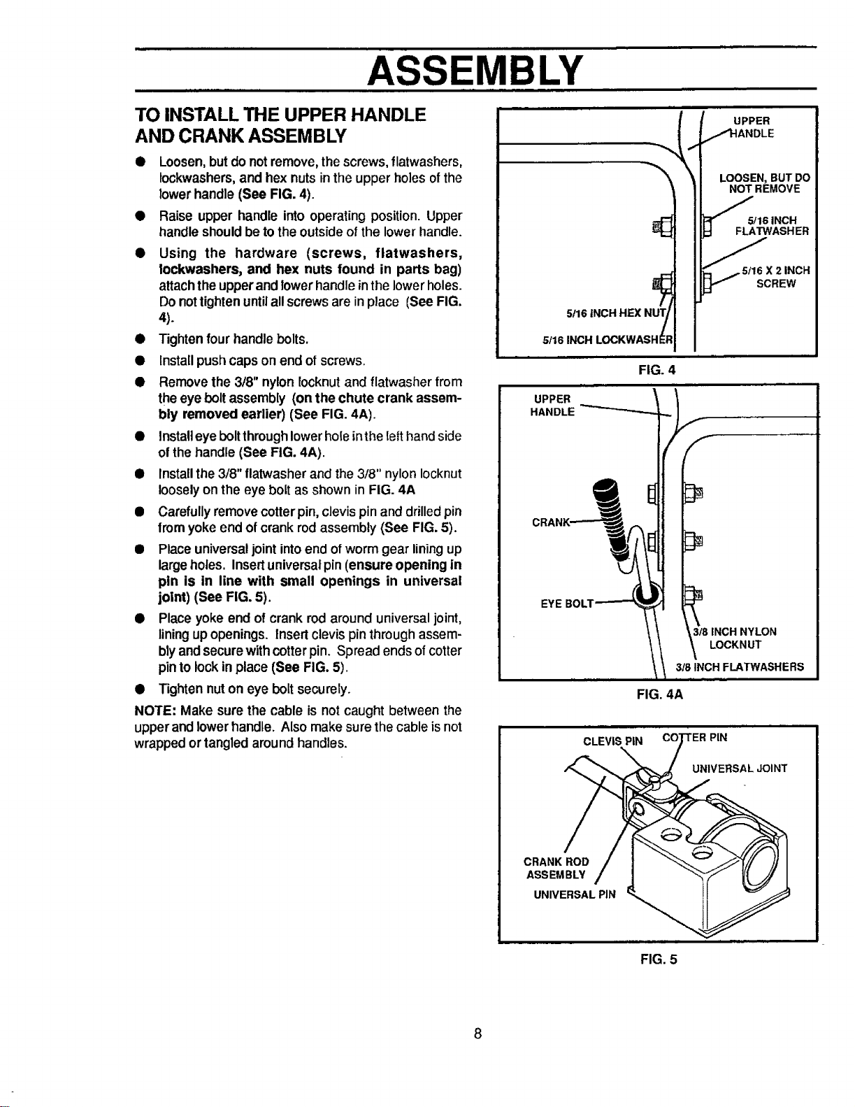
TO INSTALL THE UPPER HANDLE
AND CRANK ASSEMBLY
• Loosen, but do notremove, the screws, flatwashers,
lockwashers, and hex nuts in the upper holes of the
lower handle (See FIG. 4).
• Raise upper handle into operating position. Upper
handle should be to the outside of the lower handle.
• Using the hardware (screws, flatwashers,
lockwashers, and hex nuts found in parts bag)
attachtheupperand lowerhandle inthe lowerholes.
Do nottighten untilall screwsare inplace (See FIG,
4).
• Tightenfour handle bolts.
• Install pushcaps on end of screws.
• Remove the 3/8" nylon Iocknutand flatwasher from
theeye bolt assembly (on the chute crank assem-
bly removed earlier) (See FIG. 4A).
• Install eye bolt through lowerhole inthe Ietthand side
of the handle (See FIG. 4A).
• Install the 3/8" flatwasherand the 3/8" nylon Iocknut
loosely on the eye bolt as shown in FIG. 4A
• Carefully remove cotter pin, clevis pin and drilled pin
from yoke end of crank rod assembly (See FIG. 5).
• Place universal joint into end of worm gear lining up
large holes. Insert universal pin (ensure opening in
pen is in line with small openings in universal
joint) (See FIG. 5).
• Place yoke end of crank rod around universaljoint,
liningupopenings. Insert clevis pinthroughassem-
blyand securewithcotter pin. Spread endsofcotter
pinto lockin place (See FIG. 5).
• Tighten nuton eye bolt securely.
NOTE: Make sure the cable is not caught between the
upperand lowerhandle. Also make sure the cable isnot
wrapped ortangled aroundhandles.
5!16 INCH HEX NUT/
/
5116 INCH LOCKWASHE$
FIG. 4
LOOSEN,BUTDO
NOT REMOVE
/
5/16 INCH
FLATWASHER
'/_5tl 6 X 2 INCH
SCREW
UPPER
HANDLE "_
f
/,f
3t8 INCH NYLON
LOCKNUT
318INCH
FIG. 4A
CLEVIS PiN
PIN
UNIVERSAL JOINT
CRANK ROD
ASSEMBLY
UNIVERSAL PIN
FIG. 5
8
ASSEMBLY
TO CHECK/ADJUST CLUTCH
CONTROL CABLE
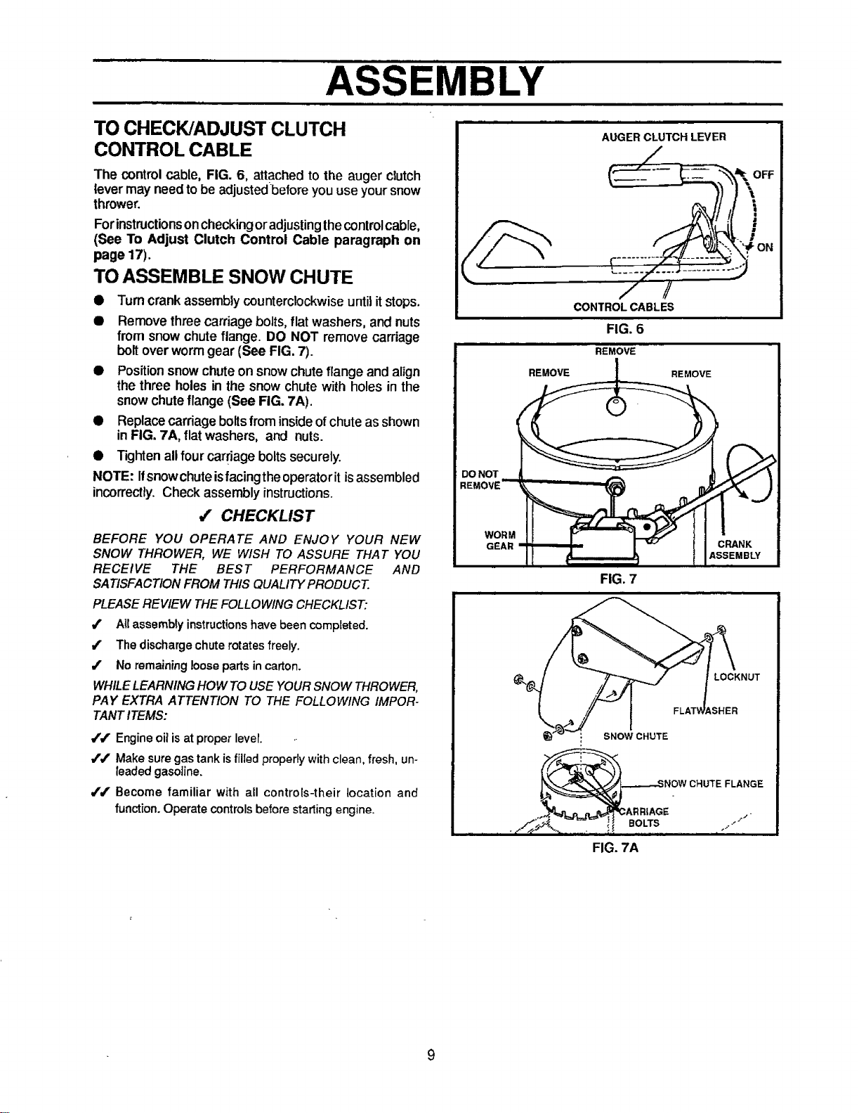
The control cable, FIG. 6, attached to the auger clutch
lever may need to be adjustedbefore you use your snow
thrower.
Forinstructionson checkingoradjusting thecontrol cable,
(See To Adjust Clutch Control Cable paragraph on
page 17).
TO ASSEMBLE SNOW CHUTE
• Turn crank assembly counterclockwise until it stops.
• Remove three carriage bolts, flat washers, and nuts
from snow chute flange. DO NOT remove carriage
bolt over worm gear (See FIG. 7).
• Position snow chute on snow chute flange and alJgn
the three holes in the snow chute with holes in the
snow chute flange (See FIG. 7A).
• Replacecarriage bolts from inside of chute as shown
in FIG. 7A, flat washers, and nuts.
• Tighten all four carriage boltssecurely.
NOTE: Ifsnowchute isfacingtheoperatorit isassembled
incorrectly. Check assembly instructions.
,f CHECKLIST
BEFORE YOU OPERATE AND ENJOY YOUR NEW
SNOW THROWER, WE WISH TO ASSURE THAT YOU
RECEIVE THE BEST PERFORMANCE AND
SATISFACTION FROM THIS QUALITY PRODUCT.
PLEASE REVIEW THE FOLLOWING CHECKLIST:
4' Atl assembly instructions have been completed.
/ The discharge chute rotates freely.
/ No remaining loose parts in carton.
WHILE LEARNING HOW TO USE YOUR SNOW THROWER,
PAY EXTRA ATTENTION TO THE FOLLOWING IMPOR-
TANT ITEMS:
/#" Engine oil isat proper lever.
/,/' Make sure gas tank is filledproperly with clean, fresh, un-
leaded gasoline.
J/ Become familiar with all controEs-their location and
function. Operate controls before starting engine.
DO NOT
REMOVE
WOR M
GEAR
AUGER CLUTCH LEVER
/_
1
/ /
CONTROL CABLES
FIG. 6
REMOVE
FIG. 7
LOCKNUT
iSHER
: SNOW CHUTE
_E ,o..,.jNOWCHUTEFLANGE
FIG. 7A
9
OPERATION
KNOW YOUR SNOW THROWER
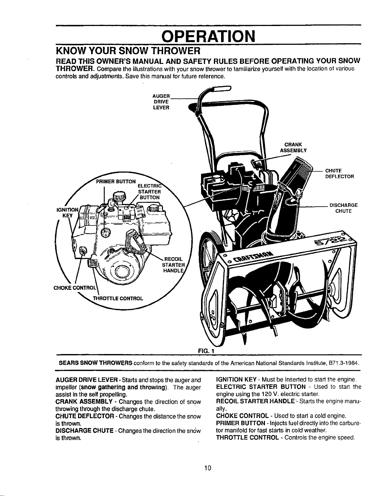
READ THIS OWNER'S MANUAL AND SAFETY RULES BEFORE OPERATING YOUR SNOW
THROWER. Compare the illustrationswith yoursnow throwertofamiliarize yourselfwith the locationof various
controlsand adjustments.Save thismanual for future reference.
AUGER
DRIVE
LEVER
CRANK
ASSEMBLY
KEY
STARTER
CHUTE
DEFLECTOR
DISCHARGE
CHUTE
STARTER
HANi
THRO'I'IrLE CONTROL
FIG. 1
SEARS SNOW THROWERS conform to the safety standards ofthe American National Standards Institute, B71.3-1984.
AUGER DRIVE LEVER - Startsand stops the augerand
impeller (snow gathering and throwing). The auger
assist inthe selfpropelling.
CRANK ASSEMBLY - Changes the direction of snow
throwingthroughthe dischargechute.
CHUTE DEFLECTOR - Changes thedistancethe snow
isthrown.
DISCHARGE CHUTE - Changes the direction the sn6w
isthrown.
IGNITION KEY - Must be inserted to start the engine.
ELECTRIC STARTER BUTTON - Used to start the
engine using the 120 V. electric starter.
RECOIL STARTER HANDLE- Starts the engine manu-
ally.
CHOKE CONTROL - Used to start a cold engine.
PRIMER BU'I-I'ON - Injects fuel directty intothe carbure-
tor manifold for fast starts in cold weather.
THROTTLE CONTROL - Controls the engine speed.
10
OPERATION
The operation ofany snowthrower can resultinforeign objects being thrown intothe
eyes, whichcan resultinsevere eye damage. Always wear safety glasses or eye
shieldswhileoperating the snow thrower.
We recommend standard safety glasses available at SEARS Retail Stores or
Service Centers.
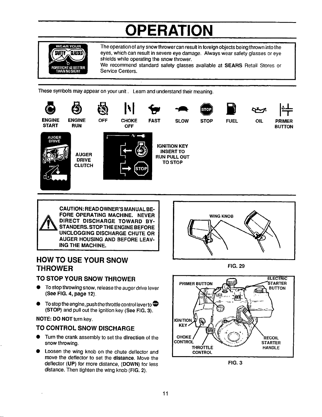
These symbols may appear on your unit. Learn and understand theirmeaning.
ENGINE ENGINE OFF CHOKE FAST SLOW STOP FUEL
START RUN OFF
OIL PRIMER
BUTTON
AUGER
DRIVE
CLUTCH
IGN_ION KEY
INSERTTO
RUN PULL OUT
TO STOP
CAUTION: READ OWNER'S MANUALBE-
FORE OPERATING MACHINE. NEVER
DIRECT DISCHARGE TOWARD BY-
STANDERS. STOP THE ENGINE BEFORE
UNCLOGGING DISCHARGE CHUTE OR
AUGER HOUSING AND BEFORE LEAV-
ING THE MACHINE.
WING KNOB
HOW TO USE YOUR SNOW
THROWER
TO STOP YOUR SNOW THROWER
To stop throwingsnow, release theauger drivelever
(See FIG. 4, page 12).
• TOstoptheengine, pushthethrottlecontrollevertoI_
(STOP) and pull outthe ignitionkey (See FIG. 3).
NOTE: DO NOT turn key.
TO CONTROL SNOW DISCHARGE
Turn the crank assembly to set the direction of the
snow throwing.
Loosen the wing knob on the chute deflector and
move the deflector to set the distance. Move the
deflector (UP) for more distance, (DOWN) for less
distance. Then tighten the wingknob (FIG. 2).
FIG. 29
PRIMER BUTTON
CHOKE
CONTROL
THROTTLE
CONTROL
FIG. 3
ELECTRIC
;R
BUTTON
STARTER
HANDLE
11
OPERATION
TO MOVE FORWARD
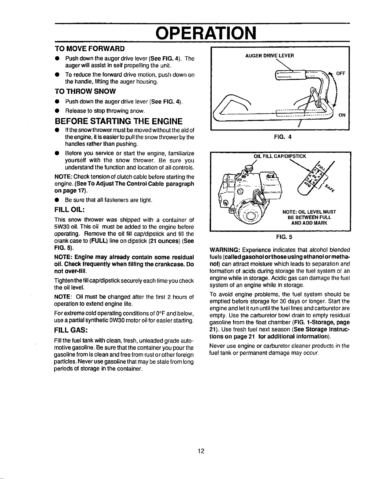
• Pushdownthe auger drive lever (See FIG. 4). The
augerwill assistin self propellingthe unit.
• To reduce the forward ddve motion,push down on
the handle, liftingthe auger fiousing.
TO THROW SNOW
• Pushdown the auger drive lever (See FIG. 4).
• Release to stopthrowing snow.
BEFORE STARTING THE ENGINE
• Ifthe snow thrower must be moved without the aid of
the engine, itis easier to pull the snow thrower bythe
handles rather than pushing.
• Before you service or start the engine, tamiliarize
yourself with the snow thrower. Be sure you
understand the function and location of all controls.
NOTE: Check tension of clutch cable before starting the
engine. (SeeTo Adjust The Control Cable paragraph
on page 17).
• Be surethat all fasteners are tight.
FILL OIL:
This snow thrower was shipped with a container of
5W30 oil. This oiJ must be added to the engine before
operating. Remove the oil fill cap/dipstick and fill the
crank case to (FULL) line on dipstick (21 ounces) (See
FIG. 5).
NOTE: Engine may already contain some residual
oil. Check frequently when fllllngthe crankcase. Do
not over-fill.
Tighten the fillcap!dipstick securely each time you check
the oil level.
NOTE: Oil must be changed after the first 2 hours of
operation to extend engine life.
Forextreme cold operating conditions of 0°F and below,
use a partial synthetic 0W30 motor oil for easier starting.
FILL GAS:
Fill thefuel tank with clean,fresh, unleaded grade auto-
motive gasoline. Be sure that the container you pour the
gasoline from is clean and free from rust orother foreign
particles. Never use gasoline that may be stale from long
periods o| storage in the container.
FIG. 4
OIL FILL CAPIDIPSTICK
i NOTE: OIL LEVEL MUST
BE BETWEEN FULL
AND ADD MARK
FIG. 5
WARNING: Experience indicates that alcohol blended
fuels (called gasohol orthose using ethanolor metha-
nol) can attract moisturewhich leadsto separation and
formationof acids during storage the fuel system of an
engine while instorage. Acidic gas can damage thefuel
system of an engine while in storage.
To avoid engine problems, the fuel system should be
emptied before storage for 30 days or longer. Start the
engine and letitrun until the fuel lines and carburetor are
empty. Use the carburetor bowl drain to empty residual
gasoline from the float chamber (FIG. 1-Storage, page
21). Use fresh fuel next season (See Storage instruc-
tions on page 21 tot additional information).
Never use engine or carburetor cleaner productsin the
fuel tank or permanent damage may occur.
12
OPERATION
TO STOP ENGINE
• To stopengine, move thethrottlecontrolleverto_I
(STOP) positionandremove key. Keep thekey ina
safe place. The enginewillnotstartwithoutthekey.
TO START ENGINE (Electric Starter)
Be sure that the engine has sufficient oil. The snow
thrower engine is equipped with a 120 volt A.C. electric
starter and recoil starter. Before starting the engine, be
certain that you have read the following information:
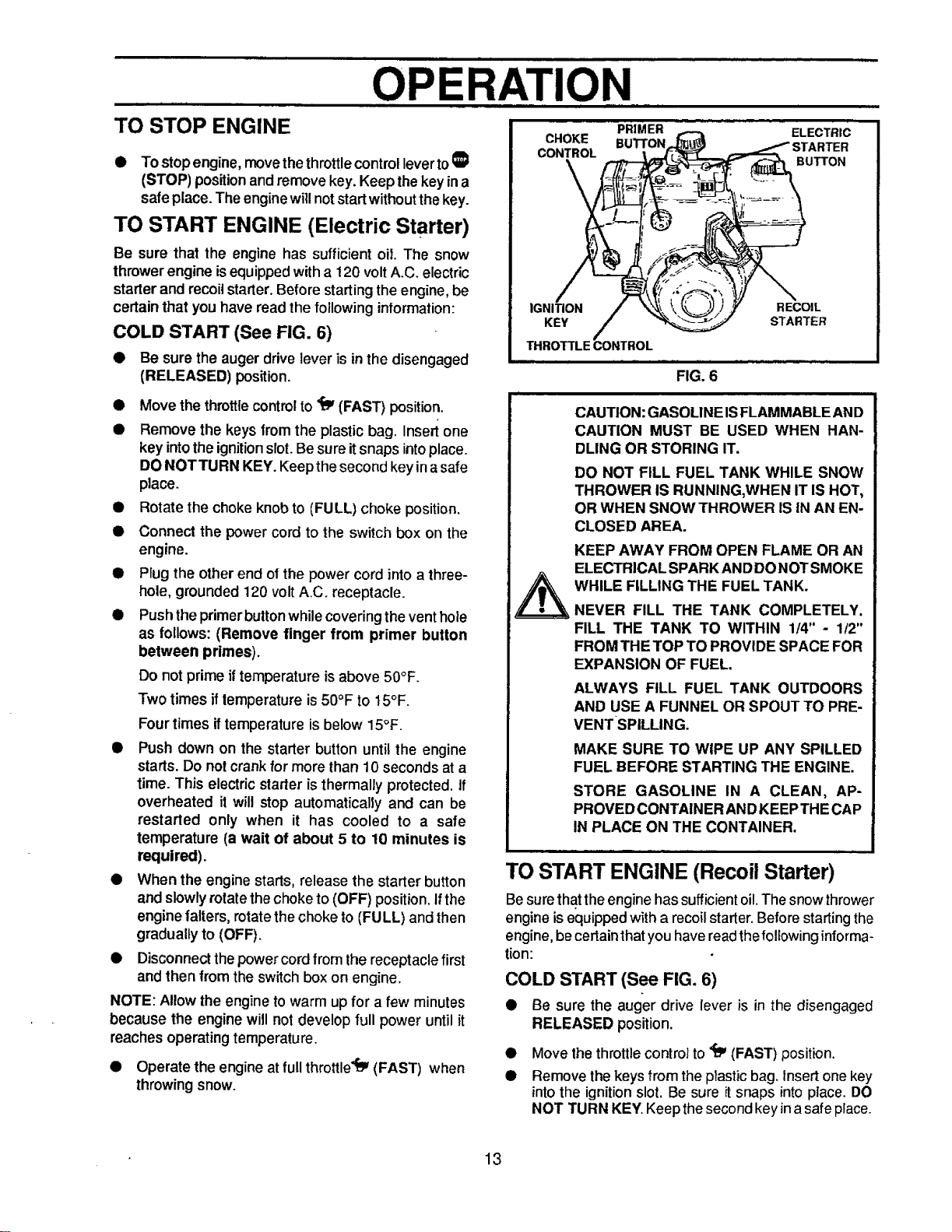
COLD START (See FIG. 6)
• Be sure the auger drive lever is in the disengaged
(RELEASED) position.
Move the throttle control to '_ (FAST) position.
Remove the keys from the plastic bag. Insert one
key intothe ignitionslot.Besure itsnaps intoplace.
DONOT TURN KEY. Keepthe second keyinasafe
place.
Rotate the choke knob to (FULL) choke position.
Connect the power cord to the switch box on the
engine.
Plug the other end of the power cord into a three-
hole, grounded 120 volt A.C. receptacle.
Push the primer button while covering the vent hole
as follows: (Remove finger from primer button
between primes).
Do not prime if temperature isabove 50°F.
Two times if temperature is 50°F to 15°F.
Four times iftemperature is below 15°F.
Push down on the starter button untilthe engine
starts. Do not crank for more than 10 seconds at a
time. This electric starter is thermally protected. If
overheated it will stop automatically and can be
restarted only when it has cooled to a safe
temperature (a wait of about 5 to 10 minutes is
required).
When the engine starts, release the starter button
and slowly rotate thechoke to(OFF) position.Ifthe
engine falters, rotate the choke to (FULL) and then
gradually to (OFF).
Disconnect thepower cord from the receptacle first
and then from the switch box on engine.
NOTE: Allow the engine to warm up for a few minutes
because the engine will not develop full power until it
reaches operatingtemperature,
• Operate the engine at full throttle_ (FAST) when
throwingsnow.
CHOKE
CONTROL
\
PRIMER
BU'I-I'ON
ELECTRIC
STARTER
BUTTON
IGNITION
KEY
THROTTLE CONTROL
FIG. 6
i
RECOIL
STARTER
CAUTION: GASOLINE ISFLAMMABLE AND
CAUTION MUST BE USED WHEN HAN-
DLING OR STORING IT.
DO NOT FILL FUEL TANK WHILE SNOW
THROWER IS RUNNING,WHEN IT IS HOT,
OR WHEN SNOW THROWER IS IN AN EN-
CLOSED AREA.
KEEP AWAY FROM OPEN FLAME OR AN
ELECTRICAL SPARK ANDDONOT SMOKE
WHILE FILLING THE FUEL TANK.
NEVER FILL THE TANK COMPLETELY.
FILL THE TANK TO WITHIN 1/4" - 1/2"
FROM THE TOP TO PROVIDE SPACE FOR
EXPANSION OF FUEL.
ALWAYS FILL FUEL TANK OUTDOORS
AND USE A FUNNEL OR SPOUT TO PRE-
VENTSPILLING.
MAKE SURE TO WiPE UP ANY SPILLED
FUEL BEFORE STARTING THE ENGINE.
STORE GASOLINE IN A CLEAN, AP-
PROVED CONTAINER ANDKEEPTHE CAP
IN PLACE ON THE CONTAINER.
TO START ENGINE (Recoil Starter)
Be surethattheengine has sufficient oil.The snow thrower
engine is equipped with a recoil starter. Before starting the
engine, be certain that you have readthefollowing informa-
tion:
COLD START (See FIG. 6)
• Be sure the auger drive lever is in the disengaged
RELEASED position.
• Move thethrottle control to _ (FAST) position.
• Remove the keys from the plastic bag. Insert one key
intothe ignition slot. Be sure itsnaps intoplace. DO
NOT TURN KEY. Keep the second key ina safe place.
13
OPERATION
WARM START
iii |1
CAUTION: NEVER RUN ENGINE
INDOORS OR IN ENCLOSED, POORLY
VENTILATED AREAS. ENGINE EXHAUST
CONTAINS CARBON MONOXIDE, AN
ODORLESS AND DEADLY GAS. KEEP
HANDS, FEET, HAIR AND LOOSE
CLOTHING AWAY FROM ANY MOVING
PARTS ON ENGINE AND SNOW
THROWER.
WARNING: TEMPERATURE OF
MUFFLER AND NEARBY AREAS MAY
EXCEED 150° F. AVOID THESE AREAS.
DO NOT ALLOW CHILDREN OR YOUNG
TEENAGERS TO OPERATE OR BENEAR
SNOW THROWER WHILE IT IS
OPERATING.
CAUTION: DO NOT ATTEMPT TO RE-
MOVE ANY ITEM THAT MAY BECOME
LODGED IN AUGER WITHOUT TAKING
THE FOLLOWING PRECAUTIONS:
_ RELEASE AUGER DRIVE LEVER.
• MOVE THROTTLE LEVER TO STOP
POSITION.
• REMOVE (DO NOT TURN) IGNITION
KEY.
• DISCONNECT SPARK PLUG WIRE.
• DO NOT PLACE YOUR HANDS IN THE
AUGER OR DISCHARGE CHUTE. USE
A PRY BAR.
@ Rotatethe choke control to (FULL) choke position.
• Push theprimer button while covering the vent hole
as follows: (Remove finger from primer button
between primes).
Do notprime iftemperatureisabove 50°F.
Two timesiftemperatureis50°F to 15°F.
Fourtimes iftemperature isbelow 15°F.
• Pulltherecoilstarterhand2erapidly.Donotallowthe
handletosnapback,butallowittorewindslowlywhile
keepinga firmholdon the starterhandle.
• As the engine warms up and begins to operate
evenly,rotatethe choke controlslowlyto the (OFF)
position.Iftheenginefalters, returnto(FULL) choke,
then slowlymoveto the (OFF) position.
NOTE: Allowthe engine to warm up for a few minutes
because the engine will not develop full power until it
reaches operatingtemperature.
• Operate the engine at full throttle "iY(FAST) when
throwingsnow.
Ifrestarting awarm engine after a short shutdown, leave
choke at (OFF) and do not push the primer button. Ifthe
engine fails to start, follow the Cold Start instructions
above.
FROZEN STARTER
If the starter is frozen and will not turn engine:
• Pullas much rope out ofthe starteras possible.
• Release the starter handle and let itsnap back
againstthe starter.
If the engine stillfails to start, repeat the two previous
steps until the engine starts. Then continuewith the
directionsfor cold start.
To helpprevent possible freeze-up of recoil starter and
engine controls, proceed as follows after each snow
removal job.
• With the engine running, pull the starter rope hard
with acontinuous full arm stroke three or four times.
Pulling of starter rope will producea loud clattering
sound. This is not harmful tothe engine or starter.
• With the engine not running, wipe all snow and
moisture from the carburetorcoverinareaofcontrol
levers.Alsomovethrottlecontrol, chokecontrol,and
starter handleseveral times.
SNOW THROWING TIPS
• For maximum snow thrower efficiency operate
engine at full throttle. The engine is designed to
deliver maximum performance at full throttle and
should be run at this power setting at all times.
• Most efficient snow throwing is accomplished when
the snow is removed immediatelyafter it fails.
• For complete snow removal, s_ightlyoverlap each
path previously taken.
• The snow should be discharged downwindwhenever
possible.
• After the snow throwing job has been completed,
allow the engine to idle for a few minutes, which will
melt snow and accumulated ice off the engine.
Clean the snow thrower thoroughly after each use.
Remove ice and snow accumulation and all debris
fromthe entire snow thrower, and flushwith water (if
possible) to remove allsalt or other chemicats. Wipe
snow thrower dry.
14
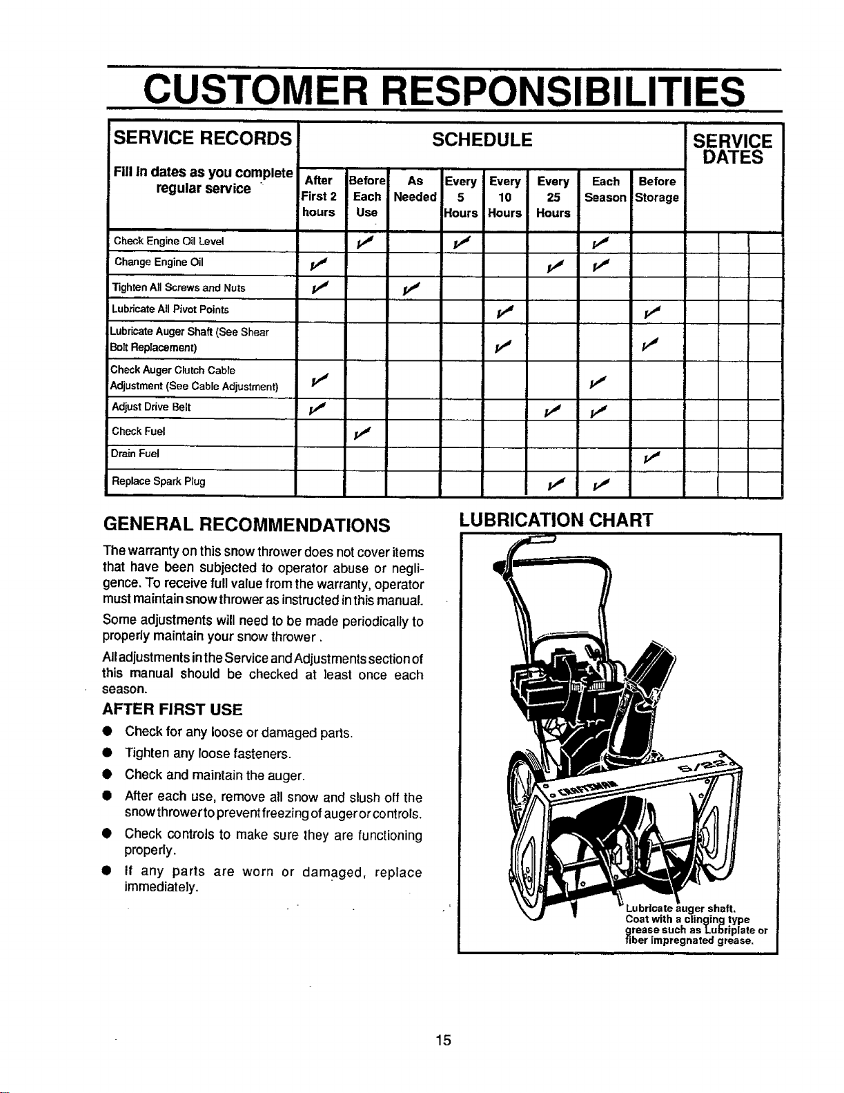
CUSTOMER RESPONSIBILITIES
SERVICE RECORDS
Fill in dates as you complete
regular service
After
First 2
hours
SCHEDULE
iii
Before As Every Every Every Each Before
Each Needed 5 10 25 Season Storage
Use Hours Hours Hours
SERVICE
DATES
m
Check Engine OilLevel _ _
Change Engine Oil j_ j_ p_
Tighten All Screws and Nuts /_ pJ
Lubricate All Pivot Points _ pJ
Lubricate Auger Shaft (See Shear
Bolt Replacement) pJ PJ
Check Auger Clutch Cable
Adjustment (See Cable Adjustment) PJ PJ
Adjust Drive Belt pJ /_
Check Fuel jr_
Drain Fuel
Replace Spark Plug p,# pj
, , ......
GENERAL RECOMMENDATIONS
The warrantyon this snowthrowerdoes notcover items
that have been subjected to operator abuse or negli-
gence. To receive fullvalue fromthe warranty, operator
mustmaintainsnowthroweras instructedinthismanual.
Some adjustmentswill need tobe made periodicallyto
properlymaintain your snowthrower.
All adjustments intheService and Adjustments section of
this manual should be checked at least once each
season.
AFTER FIRST USE
• Check for any loose or damaged parts.
• Tighten any loose fasteners.
• Check and maintain the auger.
• After each use, remove all snow and slush off the
snow throwerto prevent freezing ofaugerorcontrols.
• Check controls to make sure they are functioning
properly.
• if any parts are worn or damaged, replace
immediately.
LUBRICATION CHART
shaft.
Coat with a clinging type
grease such as Lu]_riplate or
fiber impregnated grease.
15
CUSTOMER RESPONSIBILITIES
SNOW THROWER
LUBRICATION - EVERY TEN HOURS
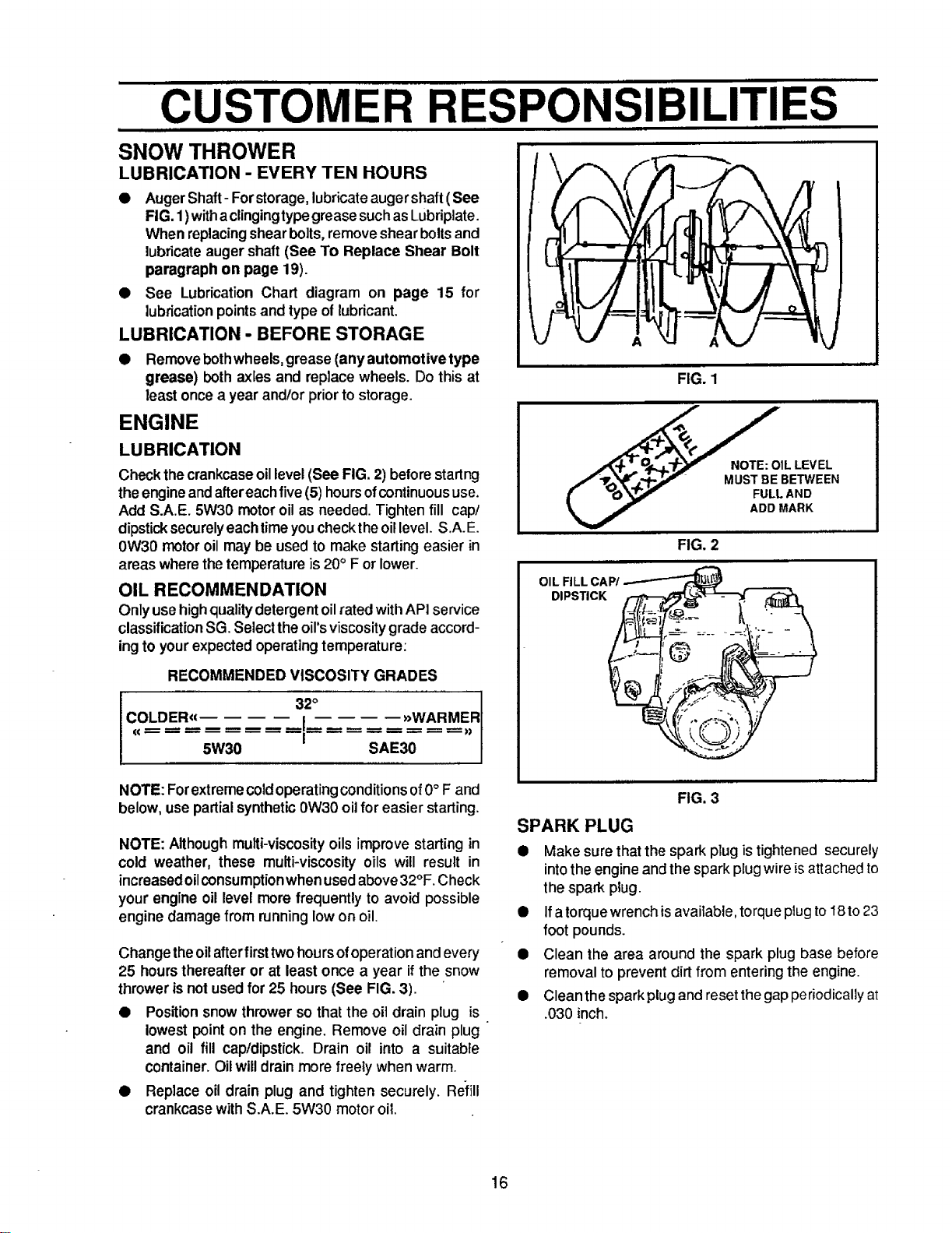
• AugerShaft- Forstorage,lubricate augershaft (See
FIG. 1)withaclingingtypegreasesuch as Lubriplate.
When replacingshearbolts,remove shear boltsand
lubricateauger shaft(See To Replace Shear Bolt
paragraph on page 19).
• See Lubrication Chart diagram on page 15 for
lubricationpointsand type of lubricant.
LUBRICATION - BEFORE STORAGE
• Removebothwheels, grease (anyautomotivetype
grease) both axles and replace wheels. Do this at
least once a year and/or priorto storage.
ENGINE
LUBRICATION
Check thecrankcaseoillevel(See FIG. 2) beforestartng
the engineand aftereachfive (5) hoursofcontinuoususe.
Add S.A.E. 5W30 motoroil as needed. Tightenfill cap/
dipsticksecurelyeachtimeyouchecktheoillevel. S.A.E.
0W30 motoroil may be used to make startingeasier in
areas where thetemperatureis 20° F or lower.
OIL RECOMMENDATION
Onlyuse highqualitydetergent oilrated withAPI service
classificationSG. Selecttheoil'sviscositygrade accord-
ingto yourexpected operatingtemperature:
RECOMMENDED VISCOSITY GRADES
I 3io
Co.DE.,, ,,w...E.,,
5W30 SAE30
A
FIG. 1
1LLEV EL
/'ff',_!lr.L',,f-_°'_ MUST BE BETWEEN
[ _0 _ FULL AND
ADD MARK
FIG, 2
OIL RLL CAP/
DIPSTICK
NOTE: Forextremecoldoperatingconditionsof0° F and
below, use partialsynthetic0W30 oilfor easier starting.
NOTE: Althoughmulti-viscosity oils improve starting in
cold weather, these multi-viscosity oils will result in
increasedoilconsumptionwhen usedabove32°F. Check
your engine oil level more frequently to avoid possible
engine damage from runninglow on oil.
Change theoilafterfirst two hours ofoperationand every
25 hours thereafter or at least once a year if the snow
thrower is not used for 25 hours (See FIG. 3).
• Position snow thrower so that the oit drain plug is
lowest point on the engine. Remove oil drain plug
and oil fill cap/dipstick. Drain oil into a suitable
container. Oilwilldrain more freely when warm.
• Replace oil drain plug and tighten securely. Refill
crankcase with S.A.E. 5W30 motor oil.
FIG. 3
SPARK PLUG
• Make sure that the spark plug istightened securely
into the engine and the spark plug wire isattached to
the spark ptug.
• If a torquewrench is available, torque plug to I8 to 23
foot pounds.
Q Clean the area around the spark plug base before
removal to prevent dirt from entering the engine.
• Clean the spark plugand reset the gap periodically at
.030 inch.
16
SERVICE AND ADJUSTMENTS
CAUTION: ALWAYS DISCONNECT THE
SPARK PLUG WIRE AND TIE BACK
AWAY FROM THE PLUG BEFORE MAK-
ING ANY ADJUSTMENTS OR REPAIRS.
TO ADJUST SIDE PLATES
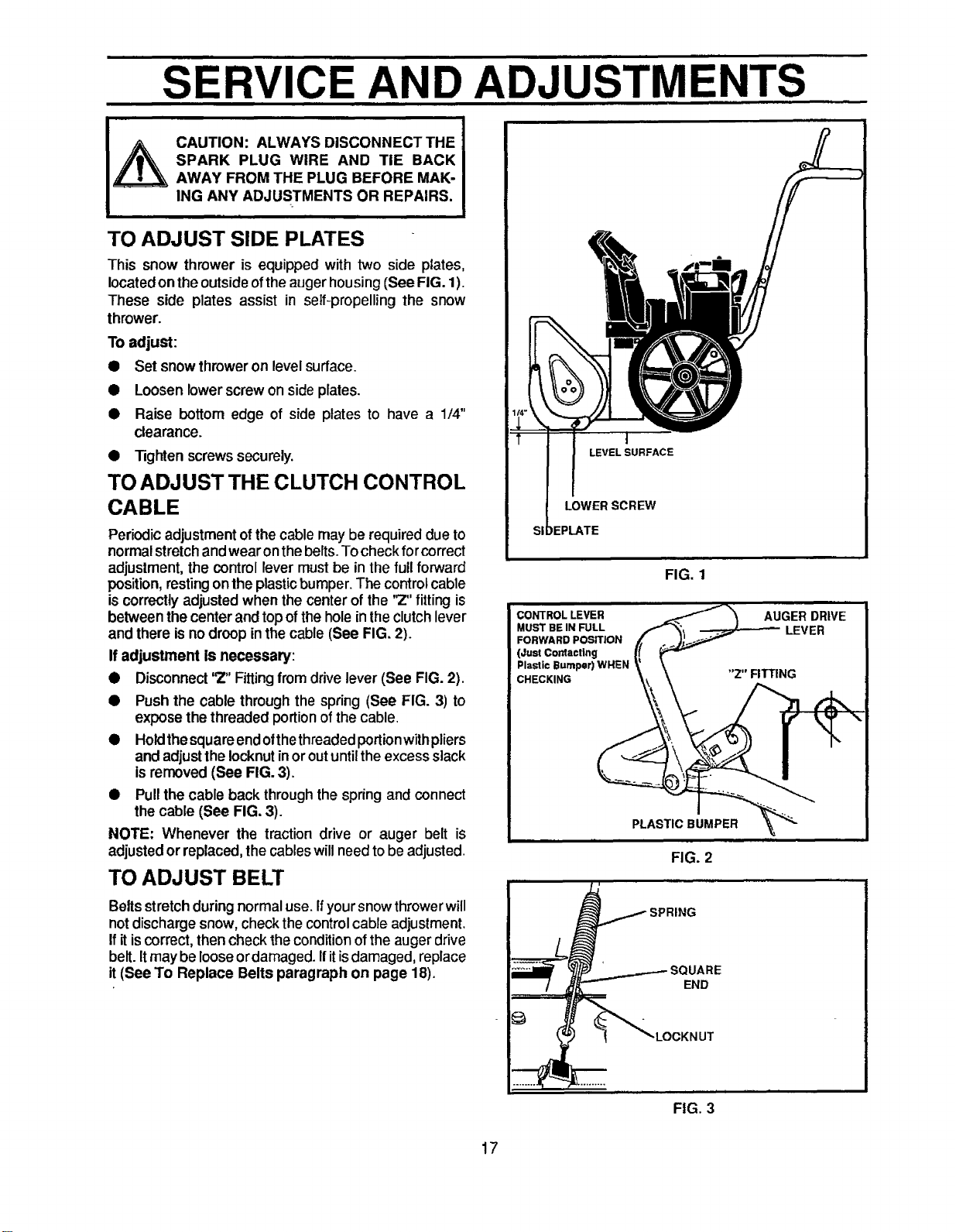
This snow thrower is equipped with two side plates,
located on the outside ofthe auger housing (See FIG. 1).
These side plates assist in self-propelling the snow
thrower.
Toadjust:
• Setsnowthroweronlevelsurface.
• Loosen lowerscrew on side plates.
• Raise bottom edge of side plates to have a 1/4"
clearance.
• Tighten screwssecurely.
TO ADJUST THE CLUTCH CONTROL
CABLE
Periodic adjustment of the cable may be required due to
normalstretch andwearon thebelts. Tocheck forcorrect
adjustment, the control lever must be in the full forward
position, resting on the plastic bumper. The control cable
is correctly adjusted when the center of the '_" fitting is
between the center and top of the hole in the clutch lever
and there is no droop inthe cable (See FIG. 2).
If adjustment is necessary:
• Disconnect'2" Fittingfrom drivelever (See FIG. 2).
• Push the cable through the spring (See FIG. 3) to
expose thethreaded portion ofthe cable.
• Holdthesquareendofthethreadedportionwithpliers
and adjusttheIocknutinoroutuntilthe excessslack
isremoved (See FIG. 3).
• Pullthe cable back through the spring and connect
the cable (See FIG. 3).
NOTE: Whenever the traction drive or auger belt is
adjusted or replaced,the cableswillneedtobe adjusted.
TO ADJUST BELT
I
LEVEL SURFACE
LOWER SCREW
IEPLATE
FIG. 1
CONTROL LEVER
MUST BE IN FULL
FORWARD POSITION
(Just Cordact|ng
Plastic Bumper) WHEN
CHECKING
PLASTIC BUMPER
FIG. 2
Beltsstretch during normal use. Ifyoursnow throwerwill
not discharge snow, check the control cable adjustment.
If itis correct, then check the condition of the auger drive
belt. Itmay be loose ordamaged. Ifitisdamaged, replace
it (See To Replace Belts paragraph on page 18).
IARE
END
FIG. 3
17
i iiml i i|1
SERVICE AND ADJUSTMENTS
TO REPLACE BELT
The drive belt on this snow thrower is of special
constructionand shouldbe replacedwithoriginalequip-
ment belts available fromyournearest SEARS Store or
Service Center.
If your snow thrower will not dischargesnow, and the
auger drive belt isdamaged, replace itas follows:
• Disconnectthe sparkplugwire,
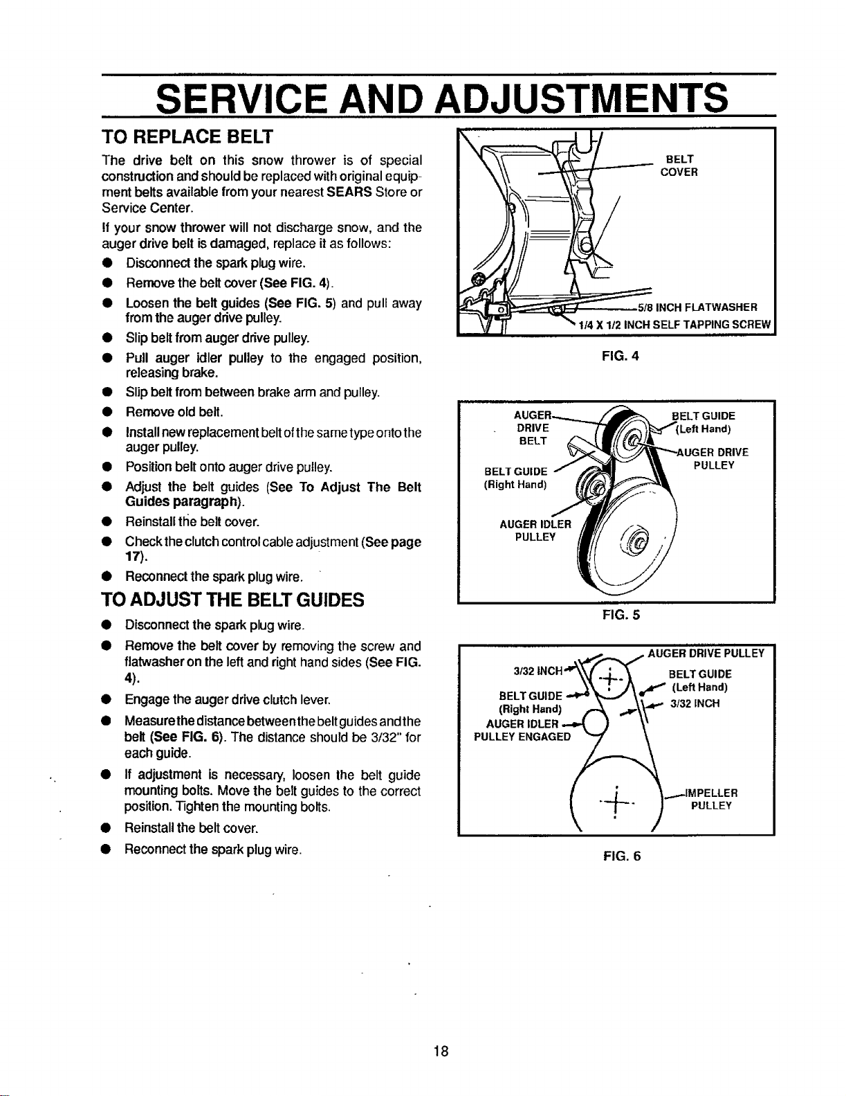
• Remove the belt cover(See FIG. 4).
• Loosen the belt guides (See FIG. 5) and pull away
from the augerdrivepulley.
• Slipbeltfrom augerdrive pulley.
• Pull auger idler pulley to the engaged position,
releasingbrake.
• Slipbeltfrom belween brake arm and pulley.
• Remove old belt.
• Installnewreplacementbeltofthesametypeontothe
augerpulley.
• Positionbelt ontoauger drivepulley.
• Adjust the belt guides (See To Adjust The Belt
Guides paragraph).
• Reinstalltl_ebelt cover.
• Checkthe clutchcontrolcableadjustment(See page
17),
• Reconnectthe spark plugwire.
TO ADJUST THE BELT GUIDES
• Disconnectthe sparkplugwire.
• Remove the belt cover by removing the screw and
flatwasheron theleft and right hand sides (See FIG.
4).
• Engage the auger drive clutch lever.
• Measurethe distance between the beltguides andthe
belt (See FIG. 6). The distance should be 3/32" for
each guide.
• If adjustment is necessary, loosen the belt guide
mounting bolts. Move the belt guides to the correct
position. Tighten the mounting bolts.
• Reinstall the belt cover.
• Reconnect the spark plug wire.
FIG. 4
DRIVE
BELT
BELT GUIDE
(Right Hand)
BELT GUIDE
Left Hand)
DRIVE
PULLEY
AUGER IDLER
PULLEY
FIG. 5
AUGER DRIVE PULLEY
3f32 INCH'__ BELT GUIDE
(,.,,..a.,)A ---\V"
FIG. 6
18
SERVICE AND ADJUSTMENTS
TO REPLACE AUGER SHEAR BOLT
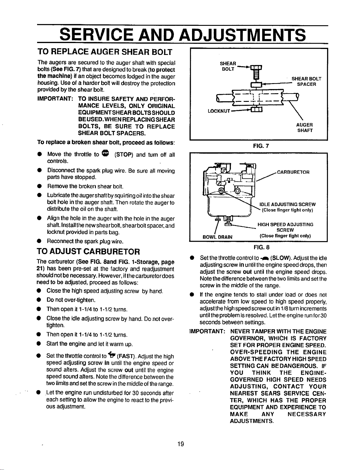
The augers are secured to the auger shaft with special
bolts (See FIG. 7) that are designed to break (to protect
the machine) if an object becomes lodged inthe auger
housing. Use of a harder bolt will destroy the protection
provided by the shear bolt.
IMPORTANT:
TO INSURE SAFETY AND PERFOR-
MANCE LEVELS, ONLY ORIGINAL
EQUIPMENTSHEAR BOLTS SHOULD
BEUSED.WHEN REPLACING SHEAR
BOLTS, BE SURE TO REPLACE
SHEAR BOLT SPACERS.
TO replace a broken shear bolt, proceed as follows:
• Move the throttle to €I (STOP) and turn off all
controls.
• Disconnect the spark plug wire. Be sure all moving
parts have stopped.
• Remove the broken shear bolt.
• Lubricate theaugershaft bysquirting oil intothe shear
bolt hole in the auger shaft. Then rotate the auger to
distribute the oil on the shaft.
• Align the hole in the auger with the hole in the auger
shaft. Insta]lthe new shear bolt, shear boltspacer,and
Iocknut provided in parts bag.
• Reconnect the spark plugwire.
TO ADJUST CARBURETOR
The carburetor (See FIG. 8and FIG. 1-Storage, page
21) has been pre-set at the factory and readjustment
shouldnotbe necessary.However,ifthecarburetordoes
need to be adjusted,proceed as follows:
• Close the high speed adjusting screw by hand.
Do not over-tighten.
Then open it 1-1/4 to 1-1/2 turns.
Close the idleadjusting screw by hand. Do notover-
tighten.
Then open it1-1/4 to 1-1/2 turns.
Start the engine and let itwarm up.
• Set thethrottlecontrol to_ (FAST). Adjust thehigh
speed adjusting screw in until the engine speed or
sound alters. Adjust the screw out until the engine
speed sound alters. Note the difference between the
two limits and set the screw inthemiddle of therange.
• Let the engine run undisturbed for 30 seconds after
each setting to allow the engine to react tothe previ-
ous adjustment.
SHEAR
BOLT
I_ SHEAR BOLT
LI _ -:" SPACER
AUGER
SHAFT
FIG. 7
'_E ADCARBURET°R
JUSTING SCREW
(Close finger tight only)
IGH SPEED ADJUSTING
SCREW
BOWL DRAIN (Close finger tight only)
FIG. 8
IMPORTANT:
Set thethrottlecontrol to._ (SLOW). Adjustthe idle
adjusting screw in untilthe engine speed drops, then
adjust the screwout untilthe engine speed drops.
Note thedifferencebetween thetwo limitsand setthe
screw inthe middleofthe range.
If the engine tends to stall under load or does not
accelerate from low speed to high speed properly,
adjustthehighspeed screwoutin1/8turnincrements
untiltheproblemis resolved.Lettheenginerun for30
secondsbetween settings.
NEVER TAMPER WITH THE ENGINE
GOVERNOR, WHICH IS FACTORY
SET FOR PROPER ENGINE SPEED.
OVER-SPEEDING THE ENGINE
ABOVE THE FACTORY HIGH SPEED
SETTING CAN BEDANGEROUS. IF
YOU THINK THE ENGINE-
GOVERNED HIGH SPEED NEEDS
ADJUSTING, CONTACT YOUR
NEAREST SEARS SERVICE CEN-
TER, WHICH HAS THE PROPER
EQUIPMENT AND EXPERIENCE TO
MAKE ANY NECESSARY
ADJUSTMENTS.
19
SERVICE AND ADJUSTMENTS
TO ADJUST OR REPLACE
THE SPARK PLUG
Ifyou have difficultystartingyoursnowthrower,youmay
need to adjust or replace the spark plug. Follow the
instructionsbelow.
Replace the spark plug if the electrodes are pitted or
burned or ifthe porcelain is cracked.
TO ADJUST:
• Clean the spark plugby carefullyscraping the elec-
trodes (do not sand blast or use a wire brush).
• Be sure the spark plug is clean and free of foreign
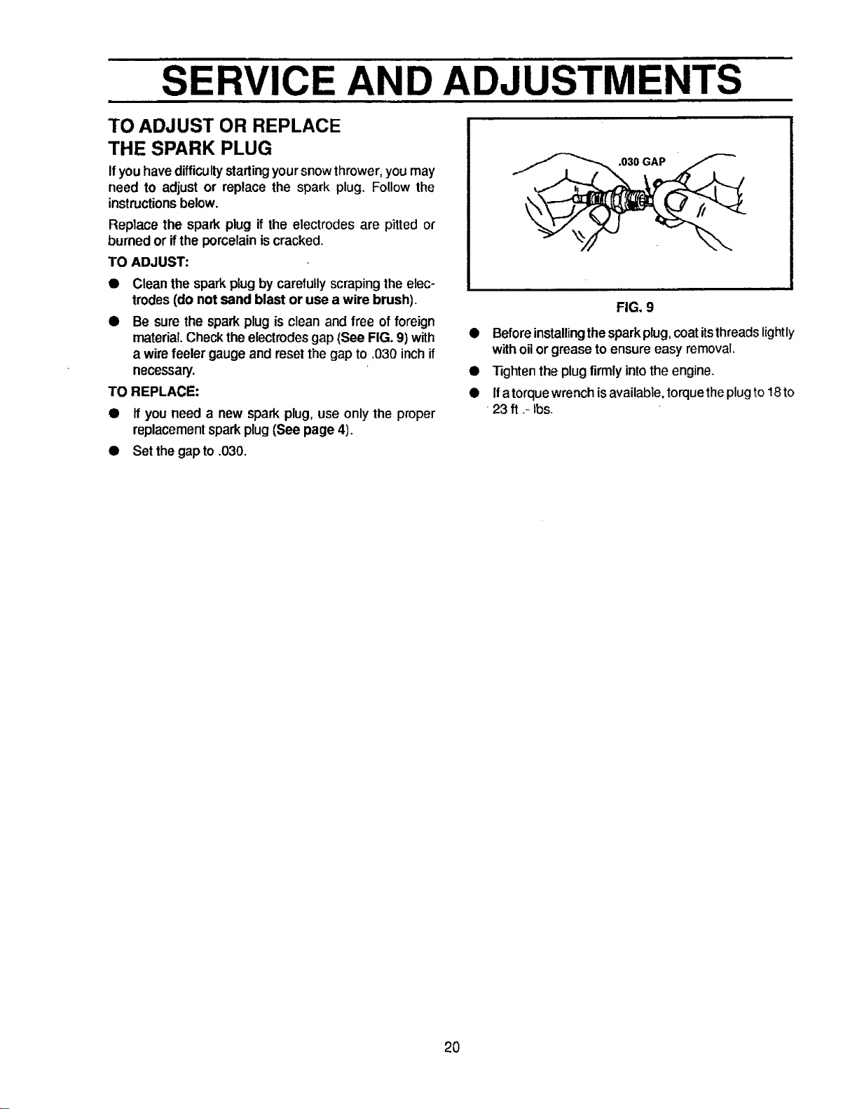
material. Check the electrodes gap (See FIG. 9) with
a wire feeler gauge and resel the gap to .030 inch if
necessary.
TO REPLACE:
• If you need a new spark plug,use only the proper
replacementspark plug (See page 4).
.030 GAP
FIG. 9
• Beforeinstallingthesparkplug,coatitsthreadslightly
withoilor grease to ensure easy removal.
• Tightenthe plugfirmly intothe engine.
• Ifatorque wrenchisavailable, torquetheplugto18to
23 ft .- Ibs.
• Set the gapto .030.
2O
STORAG
CAUTION: NEVER STOREYOUR SNOW
THROWER INDOORS OR IN AN EN-
CLOSED, POORLY VENTILATED AREA
IF GASOLINE REMAINS IN THE TANK.
FUMES MAY REACH AN OPEN FLAME,
SPARK OR PILOT LIGHT FROM A FUR-
NACE, WATER HEATER, CLOTHES
DRYER, CIGARETTE, ETC.
To preventenginedamage (Ifsnowthrower isnot used
for more than 30 days) followthe stepsbelow.
SNOW THROWER STORAGE
• Thoroughlyclean the snowthrower.
• Lubdcate all lubricationpoints(See the Customer
Responsibilities section on pages 15-16).
• Be sure that all nuts,boltsand screwsare securely
fastened. Inspect all visible moving parts for dam-
age, breakage and wear. Replace it necessary.
• Touch up all rested or chippedpaintsurfaces; sand
lightlybefore painting.
• Cover the bare metal parts of the blower housing
auger and the impellerwith rustpreventative, such
as a spray lubricant.
NOTE: Ayearlycheckuportune-upbyaSEARS Service
Centeris agoodwayto insurethatyoursnow throwerwill
provide maximum performancefor the next season.
ENGINE STORAGE
Gasollne must be removed or treated toprevent gum
deposits from forming in the tank, filter, hose, and
carburetor during storage. Also during storage, al-
cohol blended gasoline that uses ethanol or metha-
nol (sometimes called gasohol) attracts water. Itacts
on the gasoline to form acids which damage the
engine.
• To remove gasoline, run theengine untilthe tank is
empty and the engine stops. Then drain remaining
gasoline from carburetor by pressing upward on
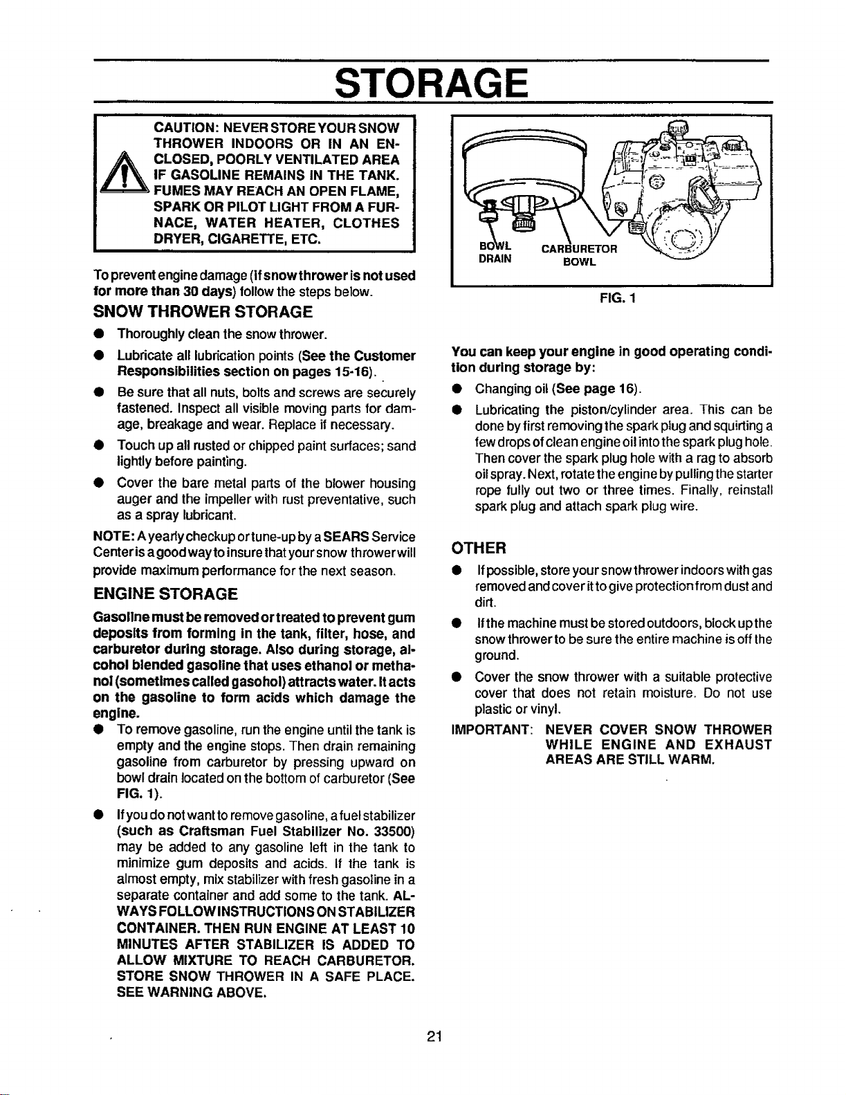
bowl drain located on the bottom of carburetor (See
FIG. 1).
• Ifyoudonot wanttoremove gasoline,afuel stabilizer
(such as Craftsman Fuel Stabilizer No. 33500)
may be added to any gasoline left in the tank to
minimize gum deposits and acids, tf the tank is
almost empty, mixstabilizerwithfresh gasoline ina
separate container and add some to the tank. AL-
WAYS FOLLOW INSTRUCTION SON STABIMZER
CONTAINER. THEN RUN ENGINE AT LEAST 10
MINUTES AFTER STABILIZER IS ADDED TO
ALLOW MIXTURE TO REACH CARBURETOR.
STORE SNOW THROWER IN A SAFE PLACE.
SEE WARNING ABOVE.
CARBURETOR
DRAIN BOWL
FIG. 1
You can keep your engine in good operating condi-
tion during storage by:
• Changingoil(See page 16).
• Lubricating the piston/cylinder area. This can be
donebyfirst removingthe sparkplug and squirting a
fewdropsofclean engine oilintothesparkplughole.
Then coverthe spark plug holewith a rag toabsorb
oilspray.Next, rotatetheenginebypullingthe starter
rope tully out two or three times. Finally, reinstall
spark plug and attach spark plug wire.
OTHER
• Ifpossible, storeyour snow thrower indoorswithgas
removed and cover ittogive protection from dust and
dirt.
IMPORTANT:
Ifthemachine mustbe stored outdoors,block upthe
snow thrower to be sure the entire machine isoff the
ground.
Cover the snow thrower with a suitable protective
cover that does not retain moisture. Do not use
plastic or vinyl.
NEVER COVER SNOW THROWER
WHILE ENGINE AND EXHAUST
AREAS ARE STILL WARM.
21
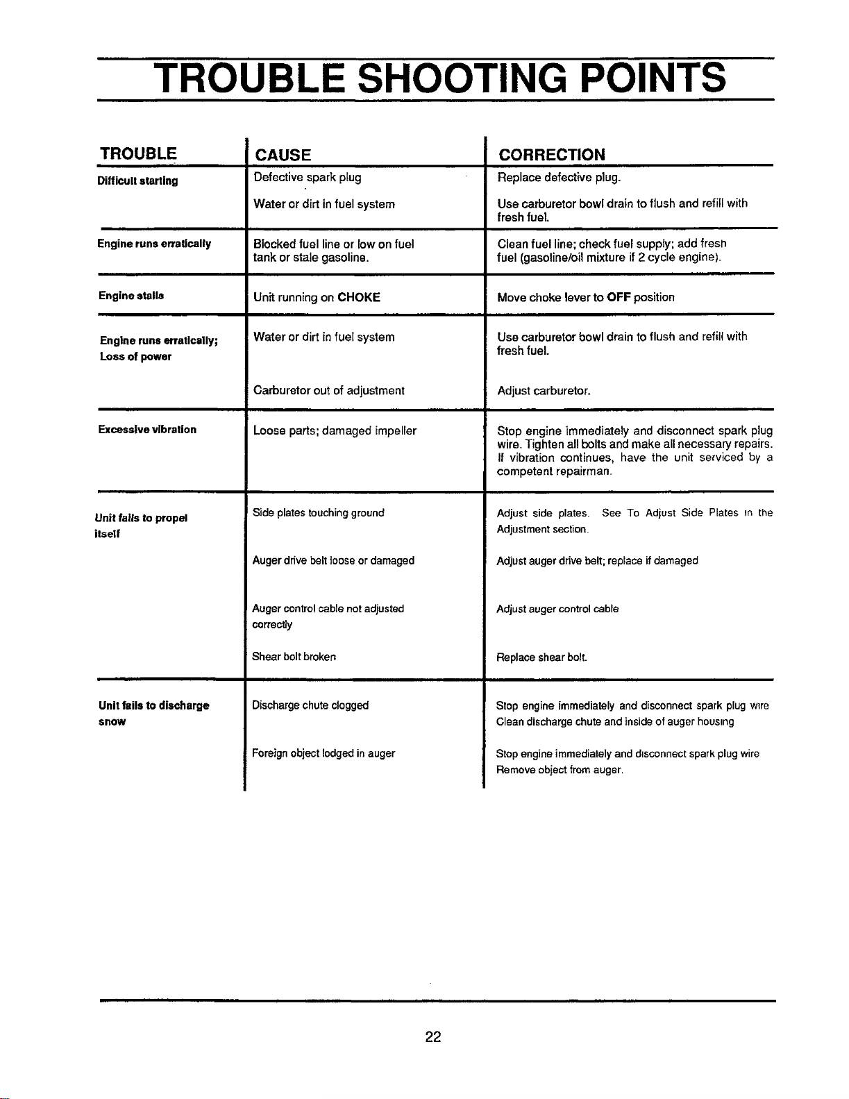
TROUBLE SHOOTING POINTS
TROUBLE
Difficultstarting
Engine runs erratically
Engine stalls
Engine runs erratically;
Loss of power
Excessive vibration
Unit fails to propel
itself
|mL
Unitfails to discharge
snow
CAUSE
Defective spark pfug
Water or dirt infuel system
Blocked fuel lineor low on fuel
tank or stalegasoline.
Unit runningon CHOKE
Water or dirt infuel system
Carburetor out ofadjustment
Loose parts;damaged impeller
i
Sideplates touchingground
Auger drive belt ]eose or damaged
Auger control cable net adjusted
correctly
Shearbeltbroken
mm
Discharge chute clogged
Foreign object lodged inauger
CORRECTION
Replace defectiveplug.
Use carburetor bowl drain to flush and refillwith
freshfuel.
Clean fuel line;check fuel supply;add fresll
fuel (gasoline/oilmixture if2 cycle engine).
Move choke lever to OFF position
Use carburetorbowl draintoflush and refill with
fresh fuel.
Adjust carburetor.
Stop engine immediately and disconnect spark plug
wire. Tightenall boltsand make all necessary repairs.
If vibration continues, have the unit serviced by a
competent repairman_
Adjust side plates. See To Adiust Side Plates in the
Adjustment section_
Adjust auger drive belt; replace ifdamaged
Adjust auger control cable
Replace shear bolt.
Stop engine immediately and disconnect spark plug w_re
Clean discharge chute and inside of auger housing
Stop engine immediately and disconnect spark plug wire
Remove object from auger,
22
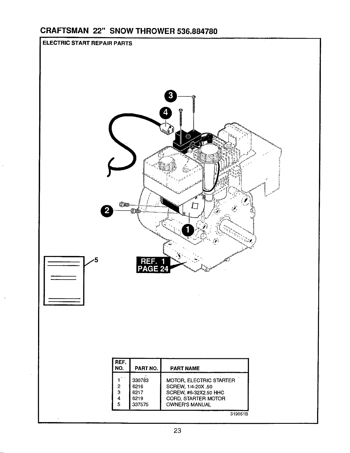
CRAFTSMAN 22" SNOW THROWER 536.884780
ELECTRIC START REPAIR PARTS
j5
\
REF.
NO.
1
2
3
4
5
PART NO.
2"
330783
6216
6217
62t 9
337575
PART NAME
MOTOR, ELECTRIC STARTER
SCREW, 1I4-20X .50
SCREW, #6-32X2.50 HHC
CORD, ,STARTER MOTOR
OWNER'S MANUAL
319051B
23
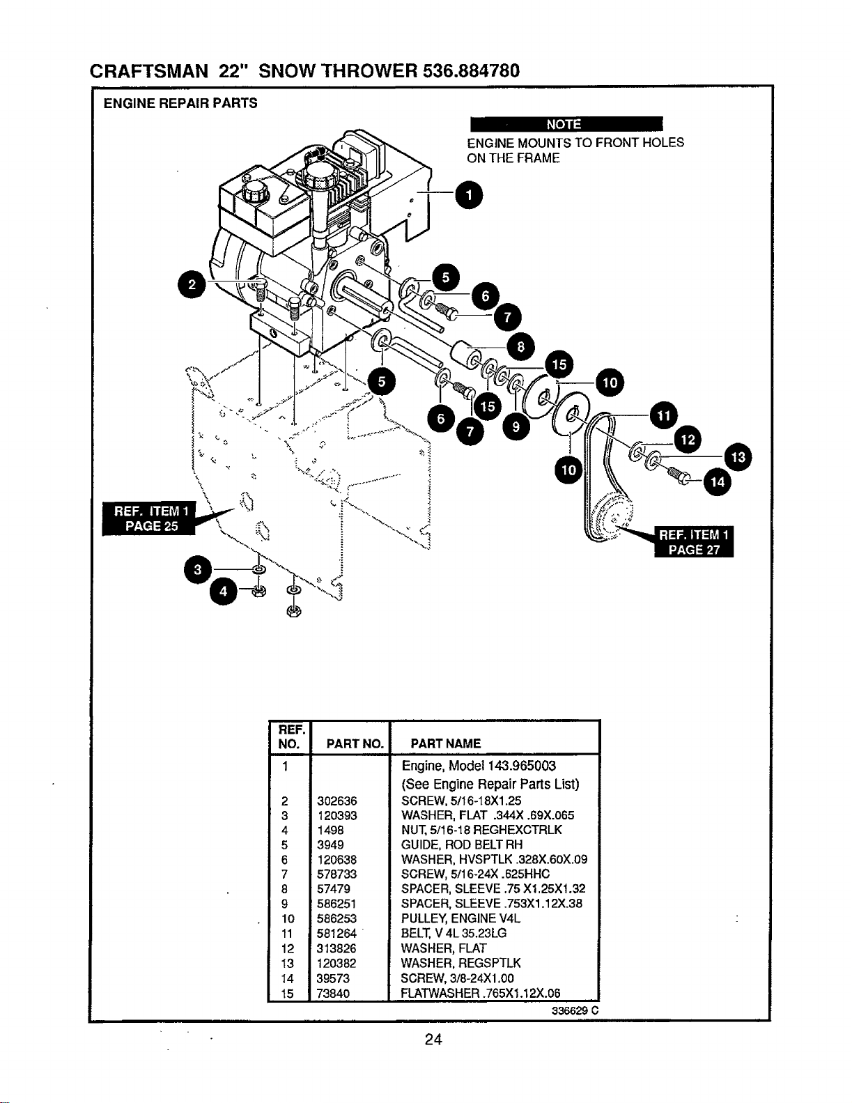
CRAFTSMAN 22" SNOW THROWER 536.884780
ENGINE REPAIR PARTS
ENGINE MOUNTS TO FRONT HOLES
ON THE FRAME
Io
\
REF.
NO. PART NO.
1
2 302636
3 120393
4 1498
5 3949
6 120638
7 578733
8 57479
9 586251
10 586253
11 581264
12 313826
13 12O382
14 39573
15 7384O
r ,
i
PART NAME
ingine, M'odel 143.965003
(See Engine Repair Parts List)
SCREW, 5/16-18Xl .25
WASHER, FLAT .344X .6gx.065
NUT,5/I 6-18 REGHEXCTRLK
GUIDE, ROD BELT RH
WASHER, HVSPTLK 328X.60X.09
SCREW, 5/16-24X .625HH0
SPACER, SLEEVE .75 X1.25X!.32
SPACER, SLEEVE .753X1.12X.38
PULLEY, ENGINE V4L
BELT, V4L 35.23LG
WASHER, FLAT
WASHER, REGSPTLK
SCREW, 3/8-24X 1.00
FLATWASHER .765Xl.12X.06
336629 C
24
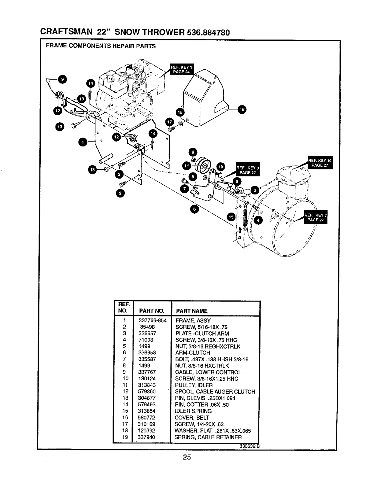
CRAFTSMAN 22" SNOW THROWER 536.884780
FRAME COMPONENTS REPAIR PARTS
REF.
NO,
1
2
3
4
5
6
7
8
9
10
11
12
13
14
15
16
17
18
19
. .. ,,,,, ,
PART NO.
337766-854
35498
336657
71003
1499
336658
335587
1499
337767
18O124
313843
579860
304877
579493
313854
580772
310169
120392
337940
PART NAME
ii i iii i
FRAME, ASSY
SCREW, 5/16-18X .75
PLATE -CLUTCH ARM
SCREW, 3/8-16X .75 HHC
NUT, 3/8-16 REGHXCTRLK
ARM-CLUTCH
BOLT,.497X .138 HHSH 3/8-16
NUT,3/8-16 HXGTR]_K
CABLE, LOWER CONTROL
SCREW, 3/8-16X1.25 HHC
PULLEY, IDLER
SPOOL, CABLE AUGER CLUTCH
PIN, CLEVIS .25DX1.094
PIN, COTTER .06X .50
IDLER SPRING
COVER, BELT
SCREW, 1/4-20X .63
WASHER, FLAT .281X .63X.065
SPRING, CABLE RETAINER
336632 B
25
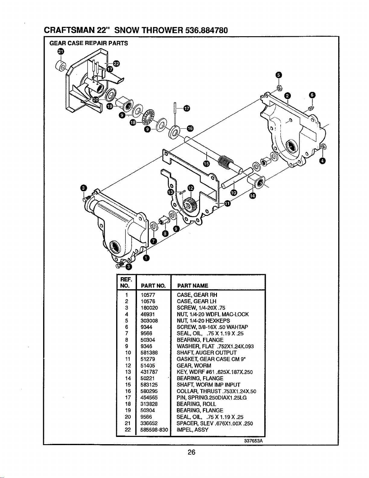
CRAFTSMAN 22" SNOW THROWER 536.884780
GEAR CASE REPAIR PARTS
O
O ®
®
O
@
O
O
REF.
NO.
1
2
3
4
5
6
7
8
9
10
11
12
13
14
15
16
17
!8
19
20
21
22
PART NO.
10577
10576
180020
46931
303008
9344
9566
50304
9346
581388
51279
51405
431787
50221
583125
580295
454565
313828
50304
9566
336652
585598-830
PART NAME
CASE, GEAR RH
CASE, GEAR LH
SCREW, 1/4-20X .75
NUT, 1/4-20 WDFL MAC-LOCK
NUT, 114-20 HEXKEPS
SCREW, 3/8-16X .50 WAHTAP
SEAL, OIL, .75 X 1.19X .25
BEARING, FLANGE
WASHER, FLAT .752Xl .24X.093
SHAFT, AUGER OUTPUT
GASKET,GEAR CASE CM 9"
GEAR, WORM
KEY,WDRF #61 °625X.187X.250
BEARING, FLANGE
SHAFT, WORM IMP INPUT
COLLAR, THRUST .753Xt.24X.50
PIN, SPRING.250DIAX1.25LG
BEARING, ROLL
BEARING, FLANGE
SEAL, OIL, .75 X 1.19 X .25
SPACER, SLEV .676Xl.00X .250
IMPEL, ASSY
337653A
26
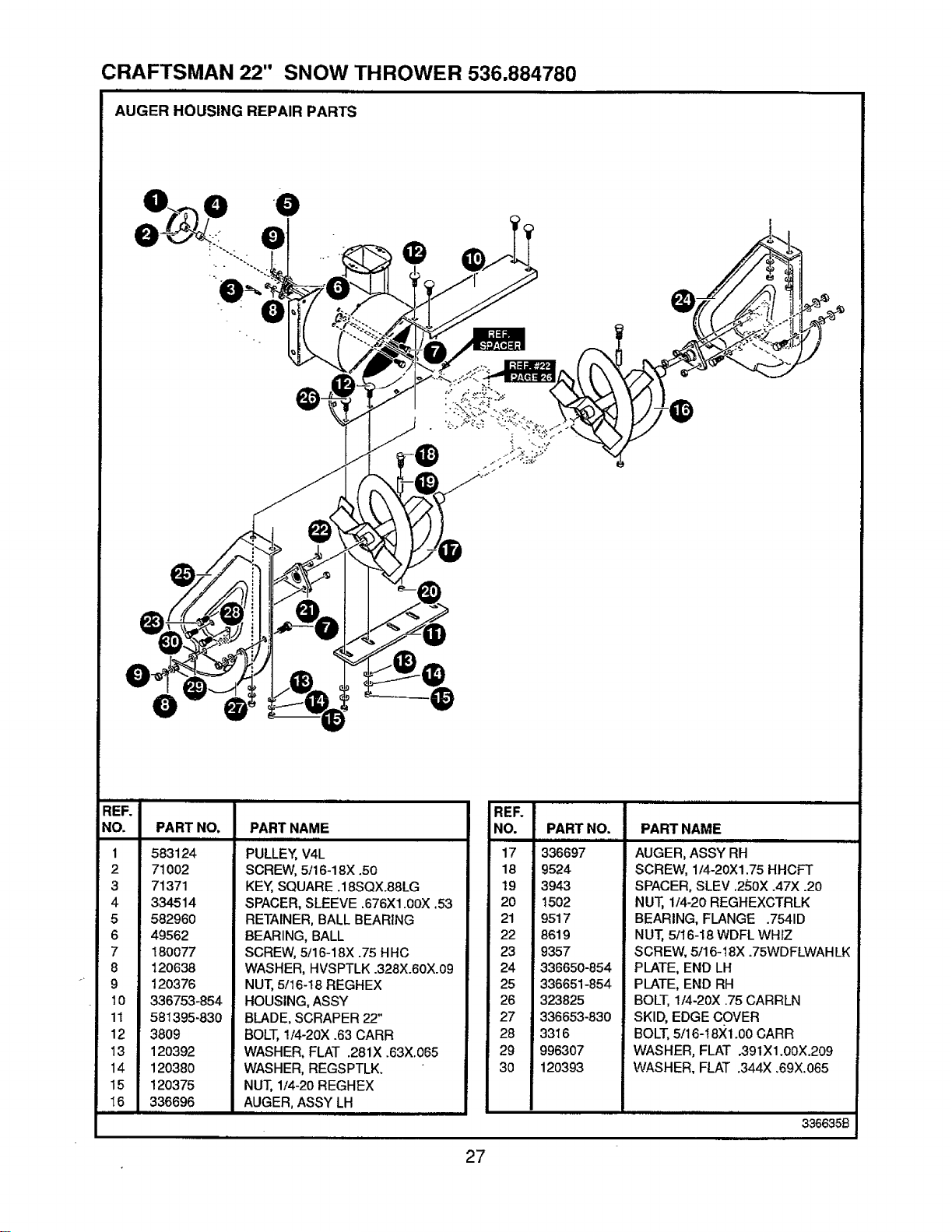
CRAFTSMAN 22" SNOW THROWER 536.884780
AUGER HOUSING REPAIR PARTS
,-"
/
REF.
NO.
1
2
3
4
5
6
7
8
-" 9
lO
11
12
13
14
15
I6
PART NO.
583124
71002
71371
334514
582960
49562
180077
120638
120376
336753-854
58t395-830
38O9
12O392
120380
! 20375
336696
PART NAME
PULLEY, V4L
SCREW, 5/16-18X .50
KEY, SQUARE .18SQX.88LG
SPACER, SLEEVE .676X1.00X .53
RETAINER, BALL BEARING
BEARING, BALL
SCREW, 5/16-18X .75 HHC
WASHER, HVSPTLK .328X.60X.09
NUT, 5/16-18 REGHEX
HOUSING, ASSY
BLADE, SCRAPER 22"
BOLT, 1/4-20X .63 CARR
WASHER, FLAT .281X .63X.065
WASHER, REGSPTLK.
NUT, 1/4-20 REGHEX
AUGER, ASSY LH
REF.
NO.
17
18
19
2O
21
22
23
24
25
26
27
28
29
30
PART NO.
336697
9524
3943
1502
9517
8619
9357
336650-854
336651-854
323825
336653-830
3316
996307
120393
PART NAME
AUGER, ASSY RH
SCREW, 1/4-20Xl .75 HHCFT
SPACER, SLEV .250X .47X .20
NUT, 1/4-20 REGHEXCTRLK
BEARING, FLANGE .7541D
NUT, 5/16-18 WDFL WHIZ
SCREW, 5/16-18X .75WDFLWAH LK
PLATE, END LH
PLATE, END RH
BOLT, 1/4-20X .75 CARRLN
SKID, EDGE COVER
BOLT, 5/16-18X1.00 CARR
WASHER, FLAT .391X1.00X.209
WASHER, FLAT .344X .69X.065
3366359
27
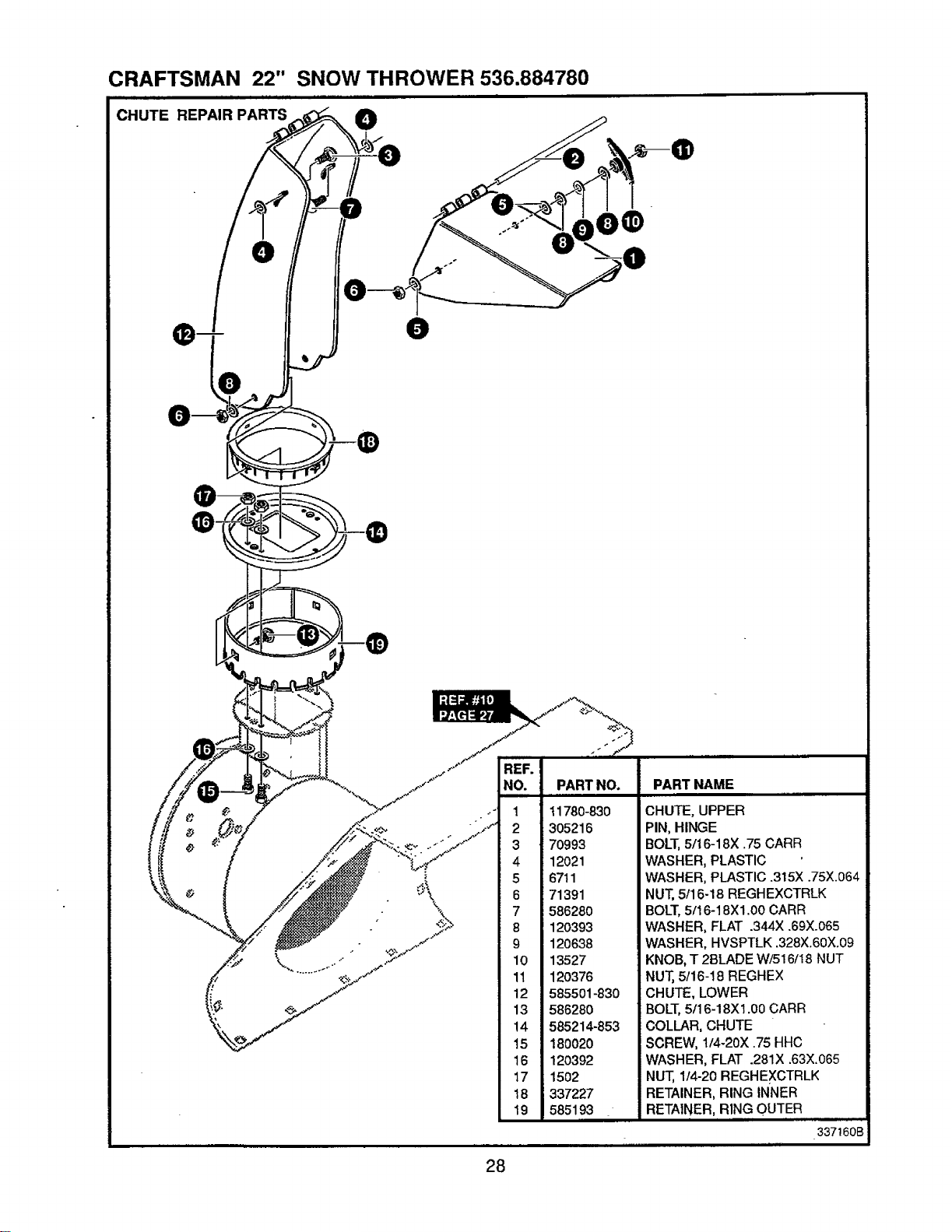
CRAFTSMAN 22" SNOW THROWER 536.884780
CHUTE REPAIR PARTS O
\
• _ ii ............
REF.
NO. PART NO. PART NAME
ii = llll
1 t1780-830 CHUTE, UPPER
2 305216 PIN, HINGE
3 70993 BOLT, 5/16-18X .75 CARR
4 12021 WASHER, PLASTIC
5 6711 WASHER, PLASTIC .315X .75X.064
6 71391 NUT, 5/16-18 REGHEXCTRLK
7 586280 BOLT, 5/16-18Xl .00 CARR
8 120393 WASHER, FLAT .344X .69X.065
9 120638 WASHER, HVSPTLK .328X.60X.09
10 13527 KNOB, T 21]LADE W/5!6/18 NUT
11 120376 NUT, 5t16-18 REGHEX
12 585501-830 CHUTE, LOWER
13 586280 BOLT, 5/16-18X1.00 CARR
14 585214-853 COLLAR, CHUTE
15 180020 SCREW, 1/4-20X .75 HHC
16 120392 WASHER, FLAT .281X .63X.065
17 1502 NUT, 1/4-20 REGHEXCTRLK
18 337227 RETAINER, RING INNER
19 585193 RETAINER, RING OUTER
337160B
28
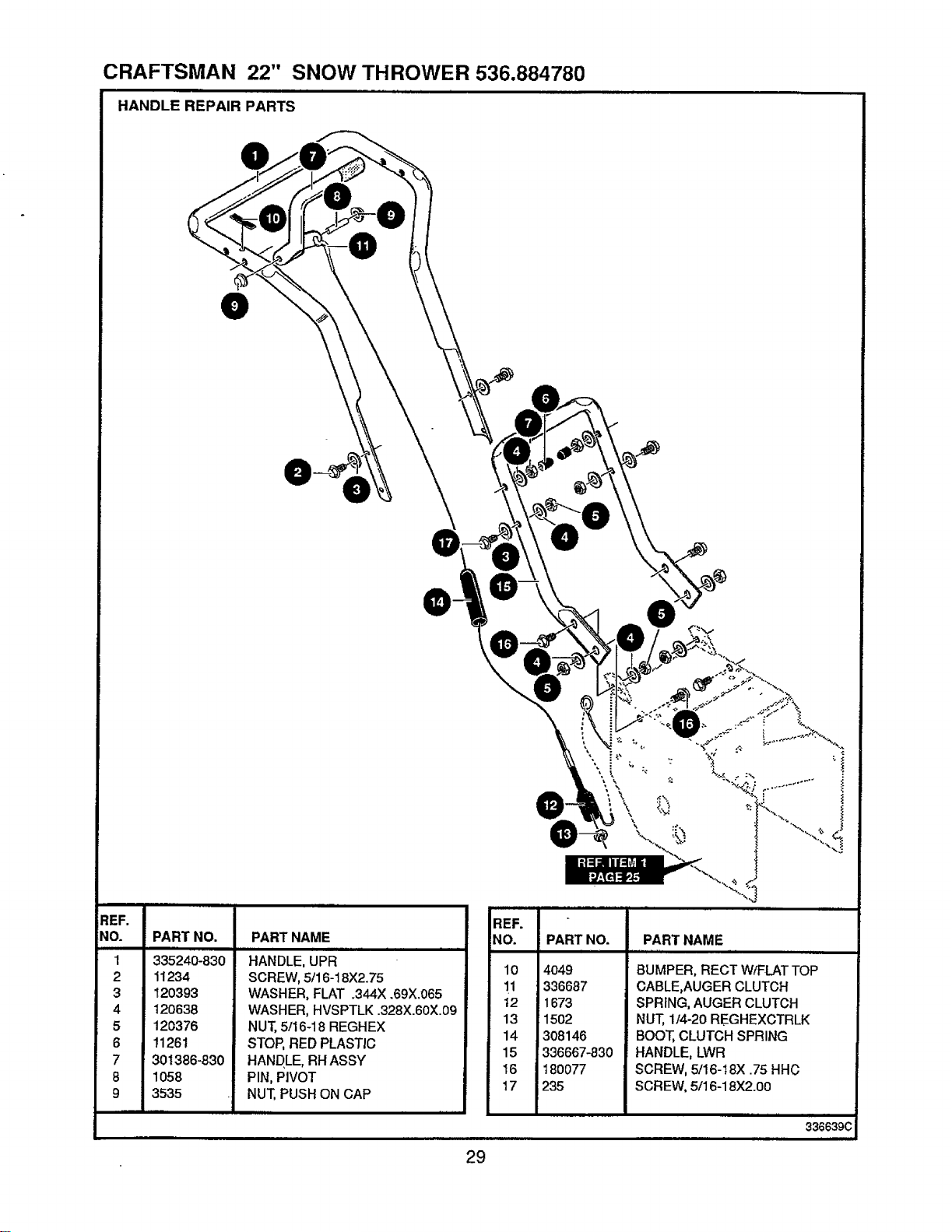
CRAFTSMAN 22" SNOW THROWER 536.884780
HANDLE REPAIR PARTS ......
REF.
NO. PART NO.
1 335240-830
2 11234
3 120393
4 120638
5 120376
6 11261
7 301386-830
8 1058
9 3535
PART NAME
HANDLE, UPR
SCREW, 5/16-18X2.75
WASHER, FLAT .344X .69X.065
WASHER, HVSPTLK .328X.60X.09
NUT, 5/16-18 REGHEX
STOP, RED PLASTIC
HANDLE, RH ASSY
PIN, PIVOT
NUT, PUSH ON CAP
irr
REF.
NO.
10
11
t2
13
14
15
16
17
PART NO.
4O49
336687
1673
1502
308146
_336667-830
18OO77
235
PART NAME
BUMPER, RECT W/FLAT TOP
CABLE,AUGER CLUTCH
SPRING, AUGER CLUTCH
NUT, 1/4-20 REGHEXCTRLK
BOOT, CLUTCH SPRING
HANDLE, LWR
SCREW, 5/16-18X .75 HHC
SCREW, 5/16-18X2.00
336639C
29
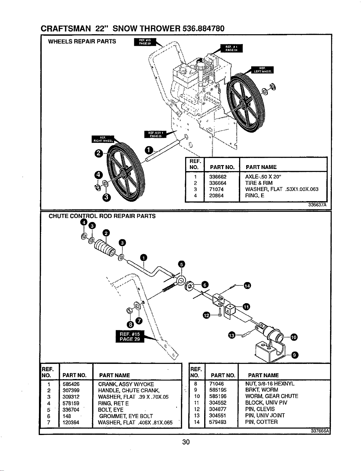
CRAFTSMAN 22" SNOW THROWER 536.884780
WHEELS REPAIR PARTS
336662
336664
71O74
20864
PART NAME
AXLE-.50 X 20"
TIRE & RIM
WASHER, FLAT .53X1.00X.063
RING, E
336637A
CHUTE CONTROL ROD REPAIR PARTS
• 0
REF.
NO.
1
2
3
4
5
6
7
\
\\
PARTNO.
585426
307399
309312
578159
336704
148
120394
PARTNAME
CRANK,ASSYW/YOKE
HANDLE,CHUTECRANK,
WASHER,FLAT .39X .70X.05
RING,RETE
BOLT,EYE
GROMMET,EYEBOLT
WASHER, FLAT .406X .81X.065
REF.
NO.
8
9
10
11
12
13
14
PART NO.
71O46
585195
585196
304552
3O4877
304551
579493
PART NAME
NUT, 3/8-16 HEXNYL
BRK'_, WORM
WORM, GEAR CHUTE
BLOCK, UNIV PIV
PIN, CLEVIS
PIN, UNIV JOINT
PIN, CO'IT['ER
337666A
30
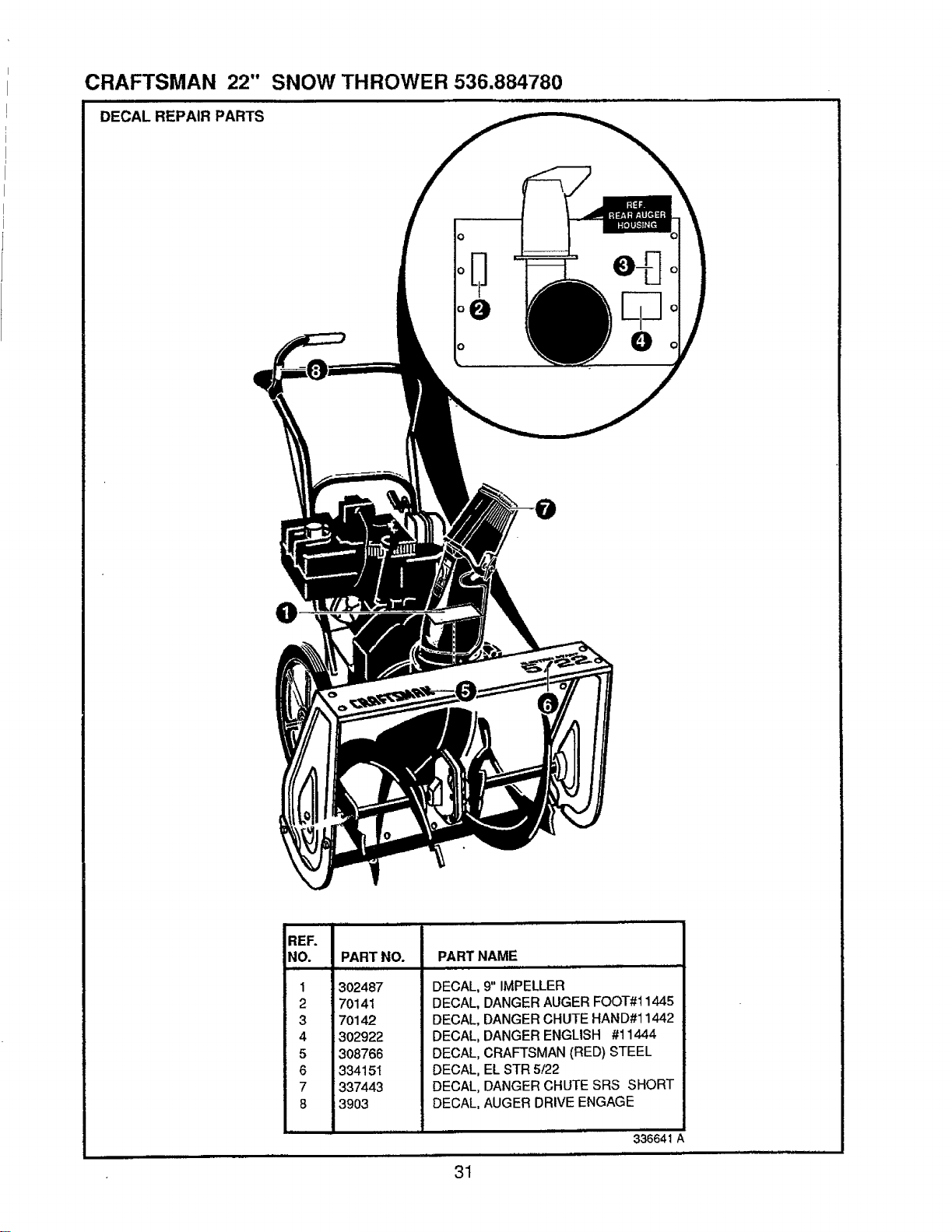
CRAFTSMAN 22"
DECAL REPAIR PARTS
SNOW THROWER 536.884780
O
REF.
NO. PART NO.
1
2
3
4
5
6
7
8
302487
70141
7Ol42
302922
308766
334151
337443
3903
PART NAME
DECAL, 9" IMPELLER
DECAL, DANGER AUGER FOOT#I 1445
DECAL, DANGER CHUTE HAND#11442
DECAL, DANGER ENGLISH #11444
DECAL, CRAFTSMAN (RED) STEEL
DECAL, EL STR 5/22
DECAL, DANGER CHUTE SRS SHORT
DECAL, AUGER DRIVE ENGAGE
31
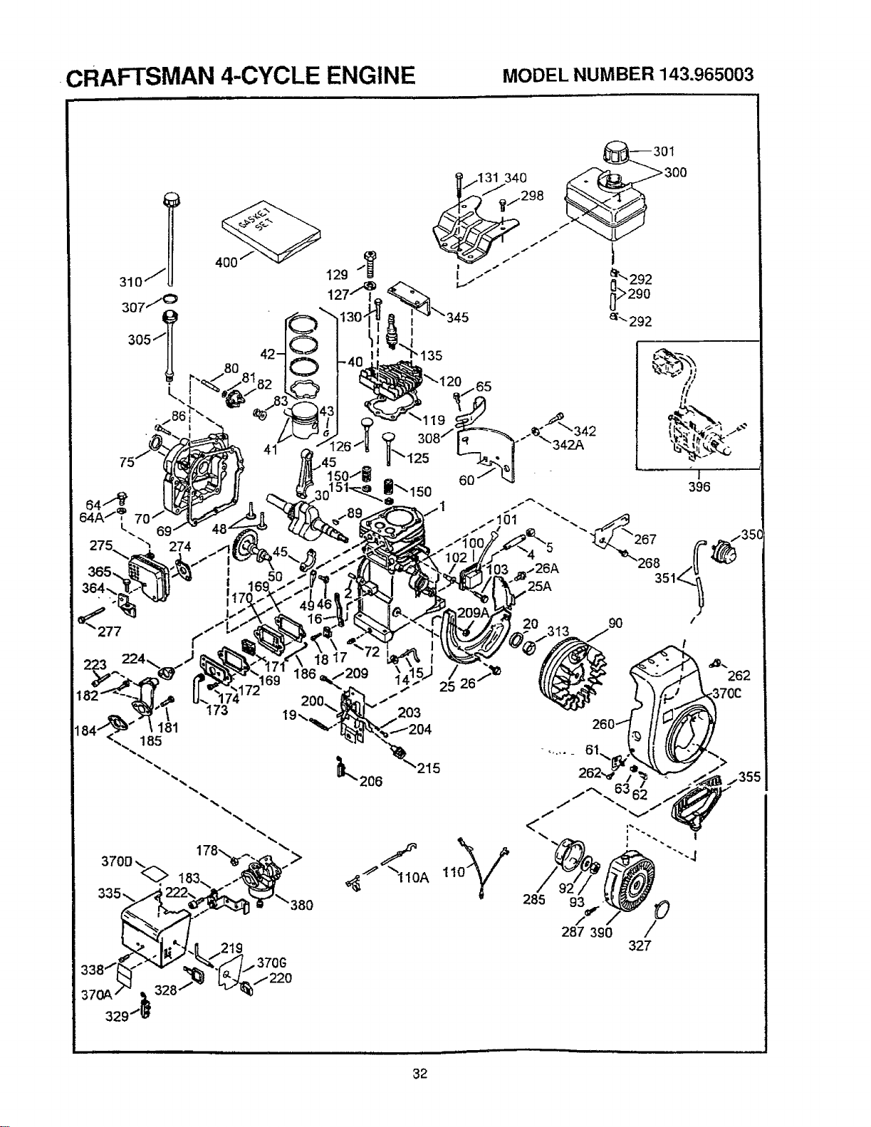
CRAFTSMAN 4-CYCLE ENGINE MODEL NUMBER 143.965003
64A / ,
L 69
4oo .._
129
262
285 93_,, O
/
287 390 /
327
32
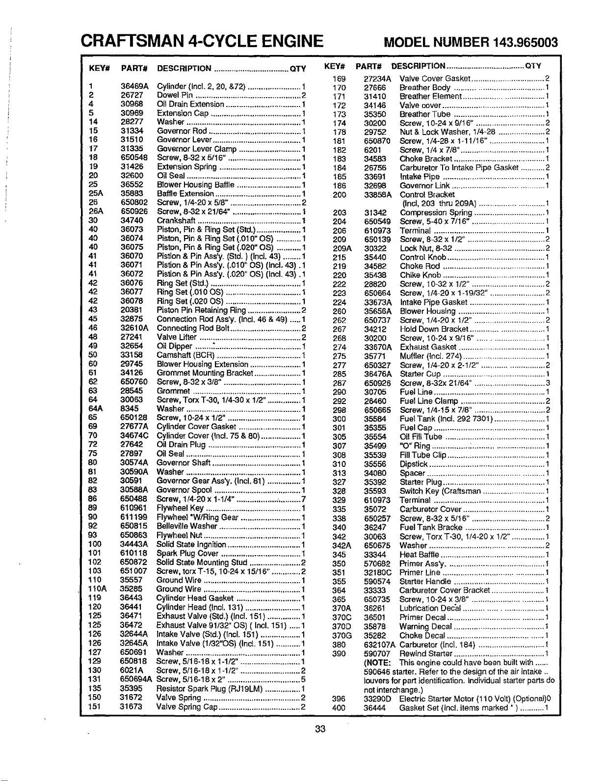
CRAFTSMAN 4-CYCLE ENGINE MODEL NUMBER143.965003
KEY# PART#
1 36469A
2 26727
4 30968
5 30969
14 28277
15 31334
16 31510
17 31335
18 650548
19 31426
20 32600
25 36552
25A 36883
26 6508O2
26A 650926
30 34740
40 36073
40 36074
40 36075
41 36070
41 36071
41 36072
42 36076
42 36077
42 36078
43 20381
45 32875
46 32610A
46 27241
49 32654
50 33158
60 29745
61 34126
62 650760
63 28545
64 30063
64A 8345
65 650128
69 27677A
70 34674C
72 27642
75 27897
80 3O574A
81 3O590A
82 3O591
83 30588A
86 650488
89 610961
g0 61119g
92 650815
93 650863
100 34443A
101 610118
102 650872
1O3 651 O07
110 35557
1t0A 35265
119 36443
120 36441
125 36471
125 36472
126 32644A
126 32646A
127 650691
129 650818
130 6021A
131 650694A
135 35395
150 31672
151 31673
DESCRIPTION .................................. OTY
Cylinder (Incl. 2, 20, &72) ........................ 1
Dowel Pin ................................................ 2
Oil Drain Extension .................................. I
Extension Cap ......................................... !
Washer .................................................... 1
Governor Rod .......................................... 1
Governor Lever ........................................ 1
Governor Lever Clamp ............................ 1
Screw, 8-32 x 5/16". ................................ 1
Extension Spring ..................................... 1
Oil Seal .................................................... 1
Blower Housing Baffle ............................. 1
Baffle Extension ....................................... 1
Screw, 1/4-20 x 5/8". ............................... 2
Screw, 8-32 x 21/64". .............................. 1
Crankshaft ............................................... 1
Piston, Pin & Ring Set (Std.) .................... 1
Piston, Pin & Ring Set (.010" OS) ........... 1
Piston, Pin & Ring Set (.020" OS) ........... 1
PislJon& Pin Ass'y. (Std.) (Incl. 43) ........ 1
Pistion & Pin Ass'y. (.010" OS) (IncL 48). 1
Pistion & Pin Ass'y. (.020" OS) (Inc!. 43). 1
Ring Set (Std.} ......................................... 1
Ring Set (.010 OS) .................................. 1
Ring Set (.020 OS) .................................. 1
Piston Pin Retaining Ring ........................ 2
Connection Rod Ass'y. (Incl. 46 & 4g) ..... 1
Connecting Rod Bolt ................................ 2
Valve Ufter .............................................. 2
Oil Dipper ........ :....................................... 1
Camshaft (BCR) ...................................... I
Blower Housing Extension ....................... 1
Grommet Mounting Bracket ..................... 1
Screw, 8-32 x 3/8". .................................. 1
Grommet ................................................. 1
Screw, Torx T-30, 1/4-30 x 1/2". .............. t
Wash er .................................................... 1
Screw, 10-24 x 1t2". ................................ 1
Cylinder Cover Gasket ............................ 1
Cylinder Cover (Inc!. 75 & 80) .................. 1
Oil Drain Plug .......................................... 1
Oil Seal .................................................... 1
Governor Shaft ........................................ 1
Washer .................................................... 1
Governor Gear Ass'y. (Incl. 81) ............... 1
Governor Spool ....................................... 1
Screw, 1/4-20 x 1-t/4". ................. ,........... 7
Flywheel Key ........................................... 1
Flywheel *W!Ring Gear ........................... 1
Belleville Washer ..................................... 1
Flywheel Nut ............................................ 1
Solid State Ingnition................................. 1
Spark Plug Cover .................................... I
Solid State Mounting Stud ....................... 2
Screw, torx T-15, 10-24 x 15/16". ............ 2
Ground Wire ............................................ 1
Ground Wire ............................................ 1
Cylinder Head Gasket ............................. 1
Cylinder Head (Incl. 131) ......................... !
Exhaust Valve (Std.) (Ind. 151 ) ............... 1
Exhaust Valve 91t32" OS) ( Incl. 151) ..... 1
Intake Valve (Std.) (Incl. 151) .................. 1
Intake Valve (1/32"OS) (Ind. 151) ........... !
Washer .................................................... 1
Screw, 5/16-! 8 x t-1/2". .......................... 1
Screw, 5/16-18 x 1-1/2". .......................... 2
Screw, 5/16-18 x 2". ................................ 5
Resistor Spark Plug (RJ19LM) ................ 1
Valve Spring ............................................ 2
Valve Spring Cap ..................................... 2
KEY#
169
170
17t
172
173
174
176
181
162
183
184
185
186
200
ii
PART# DESCRIPTION ................................... OTY
203
204
206
20g
209A
215
21g
220
222
223
224
260
262
267
268
274
275
277
285
287
29O
292
298
300
301
3O5
307
308
310
313
327
328
32g
335
338
340
342
342A
345
35O
351
355
364
365
370A
370C
370D
370G
380
390
396
4OO
27234A
27666
31410
34146
35350
30200
29752
650870
6201
34583
26756
33691
32698
33858A
31342
650549
6!0973
650139
30322
35440
34582
35438
28820
650664
33673A
35656A
650737
34212
30200
33670A
35771
650327
36476A
650926
30705
26460
650665
35584
35355
35554
35499
35539
35556
34080
35392
35593
610973
35072
650257
36247
30063
650675
33344
570682
32180C
590574
33333
650735
36261
36501
35878
35282
632107A
590707
(NOTE:
Valve Cover Gasket ................................. 2
Breather Body ........................................ 1
Breather Element .................................... 1
Valve cover .............................................. 1
Breather Tube ......................................... 1
Screw, 10-24 x g/! 6". .............................. 2
Nut & Lock Washer, 1/4-28 ..................... 2
Screw, 1/4-28 x 1-11/16". ........................ 1
Screw, 1/4 x 7/8". ..................................... 1
Choke Bracket ......................................... 1
Carburetor To Intake Pipe Gasket ........... 2
Intake Pipe .............................................. 1
Governor Link ......................................... 1
Control Bracket
(Incl, 203 thru 209A) ............................. 1
Compression Spring ................................ 1
Screw, 5-40 x 7/16". ................................ 1
Terminal .................................................. 1
Screw, 8<32 x 112". .................................. 2
Lock Nut, 8-32 ......................................... 2
Control Knob ............................................ 1
Choke Rod .............................................. 1
Chike Knob .............................................. 1
Screw, t 0-32 x 1/2". ................................ 2
Screw, 1/4-20 x 1-19/32". ........................ 2
Intake Pipe Gasket .................................. 1
Blower Housing ....................................... 1
Screw, 1/4-20 x 1/2". ............................... 2
Hold Down Bracket ................................. I
Screw, 10-24 x 9/16". ............................ 1
Exhaust Gasket ....................................... 1
Mufffer (lncI. 274) ..................................... 1
Screw, 1/4-20 x 2-1/2". ........................... 2
Starter Cup .............................................. 1
Screw, 8-32x 21/64". ............................... 3
Fuel Line .................................................. 1
Fuel Line Clamp ...................................... 2
Screw, 1/4-15 x 7/8". ............................... 2
Fuel Tank (Ind. 292 730I) ....................... 1
Fuel Cap .................................................. 1
Oi! Fill Tube ............................................. 1
"O" Ring ................. :................................ 1
Fill Tube Clip ............................................ 1
Dipstick .................................................... 1
Spacer .................................................... 1
Starter Plug .............................................. 1
Switch Key (Craftsman ............................ 1
Terminal .................................................. 1
Carburetor Cover ..................................... 1
Screw, 8-32 x 5116". ................................ 2
Fuel Tank Bracke .................................... 1
Screw, Torx T-30, 1/4-20 x 1/2". .............. I
Wash er ................................................... 2
Heat Baffle ............................................... 1
Primer Ass'y ............................................ 1
Primer Line ............................................. 1
Starter Handte ......................................... I
Carburetor Cover Bracket ........................ 1
Screw, 10-24 x 3/8". ............................... t
Lubrication Decal .................................. 1
Primer Decal ........................................... 1
Warning Decal ......................................... 1
Choke Decal ........................................... t
Carburetor ([ncl. t84) ..............................
Rewind Starter ......................................... 1
This engine could have been built with ......
590646 starter. Refer to the design of the air intake ..
louvers for part identilication, individual starter parts do
not interchange.)
33290D Electric Starter Motor (110 Volt) (Optional)0
36444 Gasket Set (incl. items marked * ) ........... 1
33
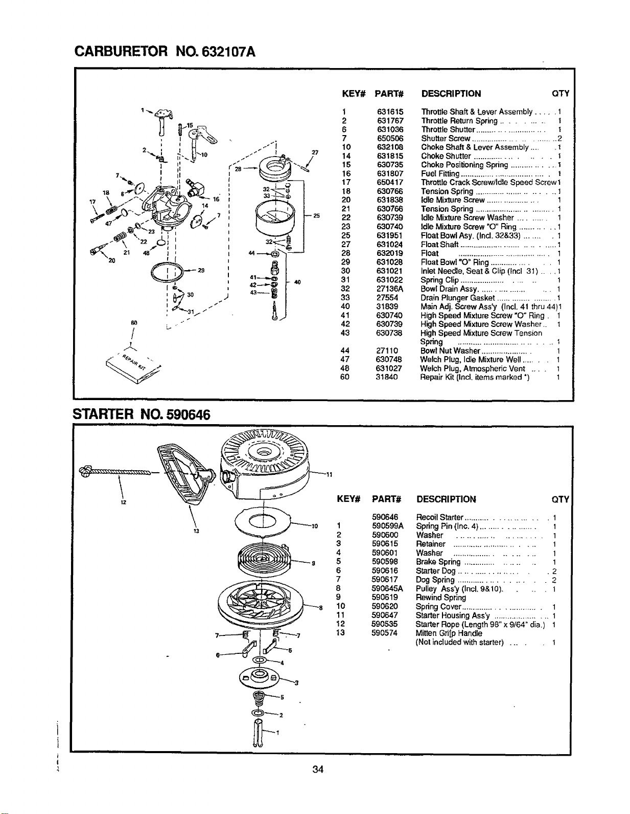
CARBURETOR NO. 632107A
i
!
1
t
!
7. I II
I1
/
!
/
. J-
L.-
i _ _ I 17
i
zz.;_
44
g
L
KEY# PART#
1 631615
2 631767
6 631036
7 650506
10 632108
14 631815
15 630735
16 631807
17 650417
18 630766
2O 631838
21 63O766
22 630739
23 63O740
25 631951
27 631024
28 632019
29 631028
30 631O21
31 631022
32 27136A
33 27554
40 31839
41 630740
42 630739
43 630738
44 27110
47 630748
48 631027
60 31840
DESCRIPTION QTY
Throttle Shaft & Lever Assembly ..... 1
Throttle Return Spring .......... t
Throttle Shutter ........................... t
Shutter Screw .............................. 2
Choke Shaft & Lever Assembly ..... t
Choke Shutter ..................... t
Choke PositioningSpring ............... I
Fuel Fitting..................................... t
Throttle Crack Screw/Idle Speed Screw 1
Tension Spring ............................ t
Idle Mixture Screw ..................... 1
Tension Spring ................................ 1
Idle Mixture Screw Washer .......... 1
Idle Mixture Screw "O" Ring ............ 1
Float Bowl Asy. (Incl. 32&33) ........ 1
FloatShaft .................................... 1
Float ....................................... 1
Float Bowl "O" Ring .................. 1
Inlet Needle, Seat & Clip (lncl 3t) .... 1
Spring Clip ......................... 1
Bowl Drain Assy ..................... 1
Drain Plunger Gasket ....................... 1
Main Adj. Scxew Ass'y (Incl. 41 thru 44)1
High Speed Mixture Screw "O" Ring. 1
High Speed Mixture Screw Washer.. 1
High Speed Mixture Screw Tension
Spring ................................... t
Bowl Nut Washer ...................... 1
Welch Plug, Idle Mixture Well ....... 1
Welch Plug, Atmospheric Vent .... 1
Repair Kit (Incl, items marked *) 1
STARTER NO. 590646
t_z KEY# PART#
590646
10 1 590599A
2 590800
3 590615
4 590601
s 5 590598
6 590616
7 590617
8 590645A
9 590619
10 590620
11 590647
12 590535
t3 590574
DESCRIPTION QTY
Recoil Starter ........................ 1
Spring Pin (Inc. 4) ................... 1
Washer ....................... 1
Retainer .............................. 1
Washer .......................... 1
Brake Spring .................... 1
Starter Dog ..................... 2
Dog Spring ....................... 2
Pulley Ass'y (Incl. 9&10). I
Rewind Spring
Spring Cover .............................. 1
Starter Housing Ass'y ...................... 1
Starter Rope (Length 98" x 9/64" dia.) 1
Mitten Gri[p Handle
(Not included with starter) .... 1
34
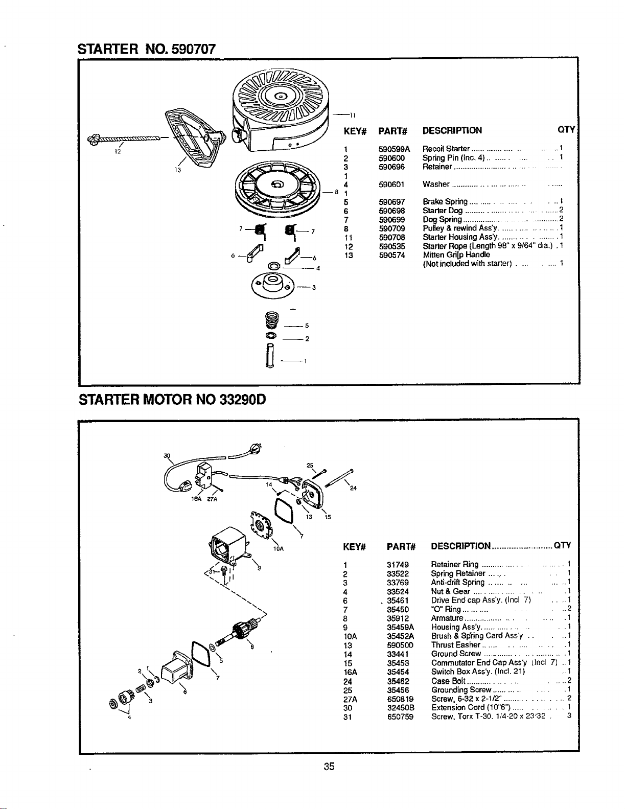
STARTER NO. 590707
i 590599A
590696
590601
--8 1
590697
590698
590699
7'_ _"--7 81 590709
590708
[_ 12 590535
6 -- --6 13 590574
O --2
DESCRIPTION
Recoil Starter ........................ 1
Spring Pin (inc. 4) .............. 1
Retainer ........................................
Washer ..................................
Brake Spring ..................... t
Starter Dog ............................... 2
Dog Spring ..................................... 2
Pulley & rewind Ass'y................... 1
Starter Housing Ass'y .................... 1
Starter Rope (Length 98" x 9/64" alia.) .1
Mitten Gri[p Handle
(Not included with starter) ......... 1
STARTER MOTOR NO 33290D
QTY
13 15
\
7
10A KEY# PART#
31749
33522
33769
33524
• 35461
35450
35912
35459A
35452A
5905OO
33441
35453
35454
35462
35456
650819
32450B
650759
DESCRIPTION ......................... QTY
Retainer Ring ........................ 1
Spring Retainer ....,. . , 1
Anti-drift Spring ................ 1
Nut & Gear ..................... 1
Drive End cap Ass'y. (Incl 7} .... I
"O" Ring ............... 2
Armature ......................... 1
Housing Ass'y .................. t
Brush & Spring Card Ass'y .... t
Thrust Easher ................. t
Ground Screw ............................. I
Commutator End Cap Ass'y (Incl 7} ..1
Switch Box Ass'y. Ilncl. 2I) . t
Case Bolt ....................... 2
Grounding Screw ................ 1
Screw, 6-32 x 2-1/2". ................. 2
Extension Cord (10"6") ............ 1
Screw, Torx T-30. 1/4-20 x 23'32 . 3
35
OWNER'S
MANUAL
MODEL NO.
536.884780
HOW TO ORDER
REPAIR PARTS
FOR REPAIR SERVICE, CALL
THIS TOLL FREE NUMBER
1-800-4-REPAIR
(1-800-473-7247)
FOR REPLACEMENT PARTS
INFORMATION AND
ORDERING, CALL THIS
TOLL FREE NUMBER:
1-800-FON-PART
(1-800-366-7278)
FOR THE LOCATION OF THE SEARS
REPAIR SERVICE CENTER
iN YOUR AREA, CALL 24 HOURS
A DAY, 7 DAYS A WEEK:
1-800-488-1222
CRAFTSMAN®
5 HORSEPOWER
22" DUAL STAGE
AUGER PROPELLED
SNOW THROWER
120V. ELECTRIC START
Each SNOW THROWER has its own MODEL
NUMBER found on the engine mount frame.
Each ENGINE has its own MODEL NUMBER
found on the BLOWER HOUSING.
Always mention these MODEL NUMBERS when
requesting service or Repair Parts for your SNOW
THROWER.
All parts may be ordered through Sears, Roebuck
and Company Service Centers and most Retail
Stores.
WHEN ORDERING REPAIR PARTS, ALWAYS
GIVE THE FOLLOWING INFORMATION:
* PRODUCT - "SNOW THROWER"
* MODEL NUMBER - 536.884780
* ENGINE MODEL NUMBER - 143.965003
* PART NUMBER
* PART DESCRIPTION
"Your Sears merchandisehas added value when you
considerthat Sears has service units nationwide staffed
with Sears trained technicians...Professional technicians
specifically trained on Sears products, having the parts,
toolsand equipment to insurethat we meet our pledge
to you...we service what we sell."
SEARS, ROEBUCK AND CO., Hoffman Estates, IL 60179
Printed in U.S.A.
36
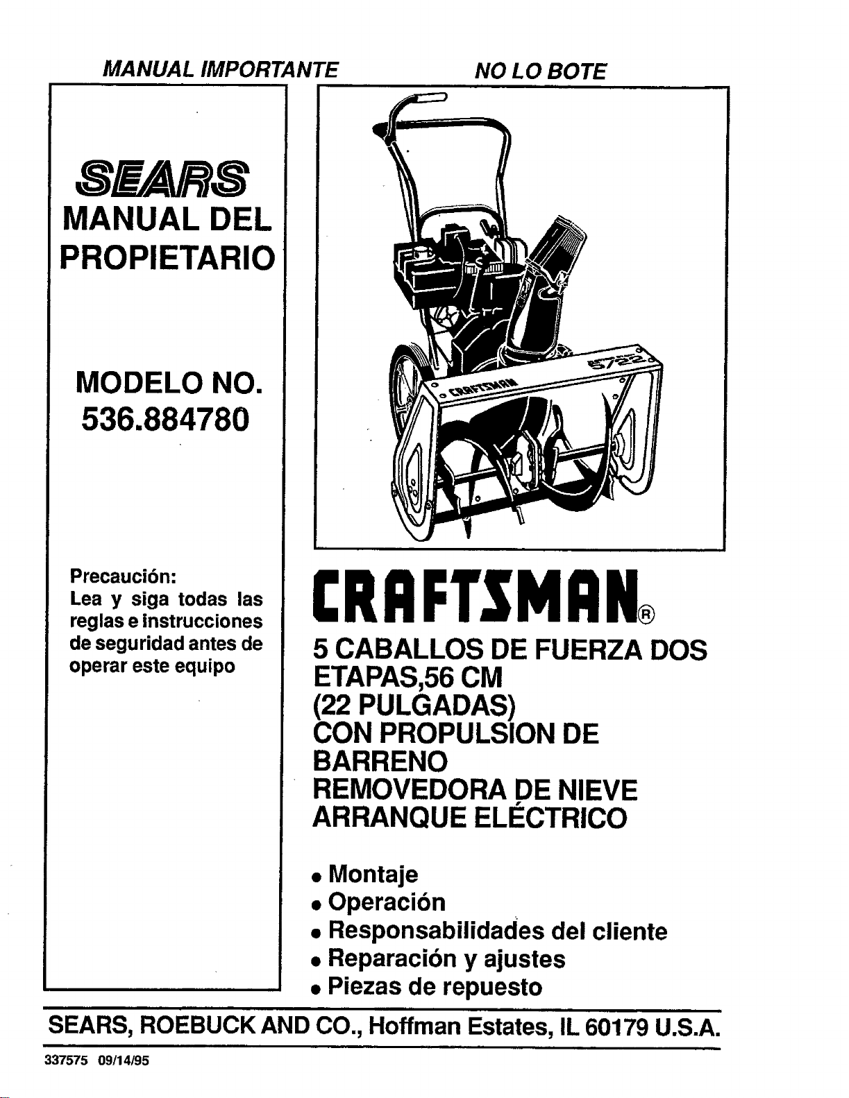
MANUAL IMPORTANTE NO LO BOTE
8 AVR8
MANUAL DEL
PROPIETARIO
MODELO NO.
536.884780
Precaucibn:
Lea y siga todas las
reglas e |nstrucciones
de seguridad antes de
operar este equipo
CRAFTSMRN
5 CABALLOS DE FUERZA DOS
ETAPAS,56 CM
(22 PULGADAS)
CON PROPULSION DE
BARRENO
REMOVEDORA DE NIEVE
ARRANQUE ELECTRICO
• Montaje
• Operacion
• Responsabilidades del cliente
• Reparacion y ajustes
• Piezas de repuesto
SEARS, ROEBUCK AND CO., Hoffman Estates, IL 60179 U.S.A.
337575 09/14/95
REGLAS DE SEGURIDAD
PRECAUCION: SIEMPRE DESCONECTE EL ALAMBRE DE LA BUJIA
,_ Y COLOQUELO DONDE NO HAGA CONTACTO CON L BUJIA PARA _
EVITAR UN ARRANQUE ACCIDENTAL AL MONTAR,
TRANSPORTAR, AJUSTAR O EFECTUAR REPARAOIONES.
IMPORTANTE
LOS ESTANDARES DE SUGURIDAD REQUIEREN LA PRESENCIA DEL OPERADOR EN LOS
CONTROLES PARA MINIMIZAR EL RIESGO DE HERIDAS. SU REMOVERDORA DE NIEVE
ESTA EQUIPADA CON DICHOS CONTROLES. NO INTENTE PASAR POR ALTO LA FUNCION
DEL CONTROL DE PRESENCIA DEL OPERADOR BAJO NINGUNA CIRCUNSTANCIA.
CAPACITACION
1. Lea el manual del operador cuidadosamente.
Famlliarlcese completamente con los controles
y el uso apropiado de la removedora de nieve. Sepa
cbmo detener laremovedora de nieve y desenganchar
los controles rdpidamente.
2. Nunca permita a ni_os operar la removedora de
nieve y msnt6ngalos fuera del alcance de la misma
mientras se encuentra en operacidn. Nunca permita
que adultos operen la removedora de nieve sin
instruccibn apropiada. No Ileve pasajeros.
3. Mantenga el 6rea libre de personas, especialmente
ninos peque_os y mascotas.
4. Tenga precaucibn a fin de evitar deslizamientos
o cafdas, especialmente al operar la removedora
de nieve en retroceso.
PREPARACION
1. lnspeccionecompletamente el drea donde se usard la
removedora de nleve yretire todas las esteras, trineos,
tableros, alambres, y otros objetos extra_os.
2. Desengsnche todos los embragues ycambie s neutro
antes de arrancar el motor.
3. Noopere laremovedora de nieve sin vestir lasprendas
de invierno adecuadas para ambientes exteriores.
Vista calzado que mejore su estabilidad en superficies
lisas.
4. Maneje el combustible con cuidado; es altamente
inflamable.
(a} Use un contenedor para combustible
aprobado.
(b) Nunca retire la tapadera del tanque de com-
bustible o a6ada combustible a un motor en
msrcha o a un motor caliente.
(c) Llene el tanque para combustible al aire libre,
con cuidado extremo. Nunca Ilene el tanque
en ambientes interiores.
(d) Coloque nuevamente la tapadera del tanque
pars combustible de manera segura y limpie
el combustible derramado.
(e) Nunca almacene combustible o la
removedora de nieve con combustible en el
tanque dentro de un edific]o donde los
vapores pudiesen entrar en contacto con
una llama desprotegida o una chispa.
(f) Veriflque ias exist_;icias de combustible an-
tes de cads uso, pel'mit;endo espacio para
expar, si6n puesto que ,.-=1cator del motor y/o
el sol pueden causer I_ expsnsibn del com-
bustible.
5. Use cables de _xtensi611 y receptdculos de la
manera esp3cificada por el fabricante pars todas
las removedoras de nieve con motores
accionados por energla el6ctrica o motores de
arranque eldctrico.
6. Ajuste la attura de la removedora de nieve pare pasar
sobre superficies de grays o piedra triturada.
7. Jamds intente efectuar ning0n ajuste mientras et mo-
tor se encuentra en marcha (excepto cuando et
fabricante Io recomiende asi especIficamente).
8. Permita que el motor y la removedora de nieve se
ajusten alas temperatures exteriores antes de
comenzar a retirar Is nieve.
9.
Slempre use galas de seguridad o protectores para
losojos durante laoperacibn o mientras se efectOa un
ajuste o reparacidn para proteger sus ojos de objetos
extra_os que pudiesen ser lanzados por laremovedora
de nieve.
OPERACION
1. No coloque las manos o los pies cerca o bajo piezas
rotativas. Mant6ngase a distancia de la abertura para
descarga todo el tiempo.
2. Tenga precaucibn extrema al operar sobre o a] cruzar
caminos, aceras, o calles de grava. Mantengase alerta
en caso de peligros ocultos o trafico.
3. Despu6s de golpear un objeto extrar_o,pare el motor,
retire el alambre de la bujla, desconecte el cable en
motores el6ctricos, inspeccione completamente la
removedora de nieve a fin de encontrar cualquier
da_o, y reparar dicho dafio antesde arrancar y operar
la removedora de nJevenuevamente.
4. En elcaso de que laremovedora de nieve comience a
vibrar fuera de Io normal, pare el motor y revise la
mdquina inmedistamente para encontrer la causa.
Generalmente, Ia vibraci6n es una advertencia de
problemas.
5. Pare el motor dondequiera que deje la posicibn de
operacibn, antes de desobstruir el alojamiento del
barreno/propulsor ogufadedescarga, ycuandoefectOe
cualesquiera reparaciones, ajustes, o inspecciones.
2
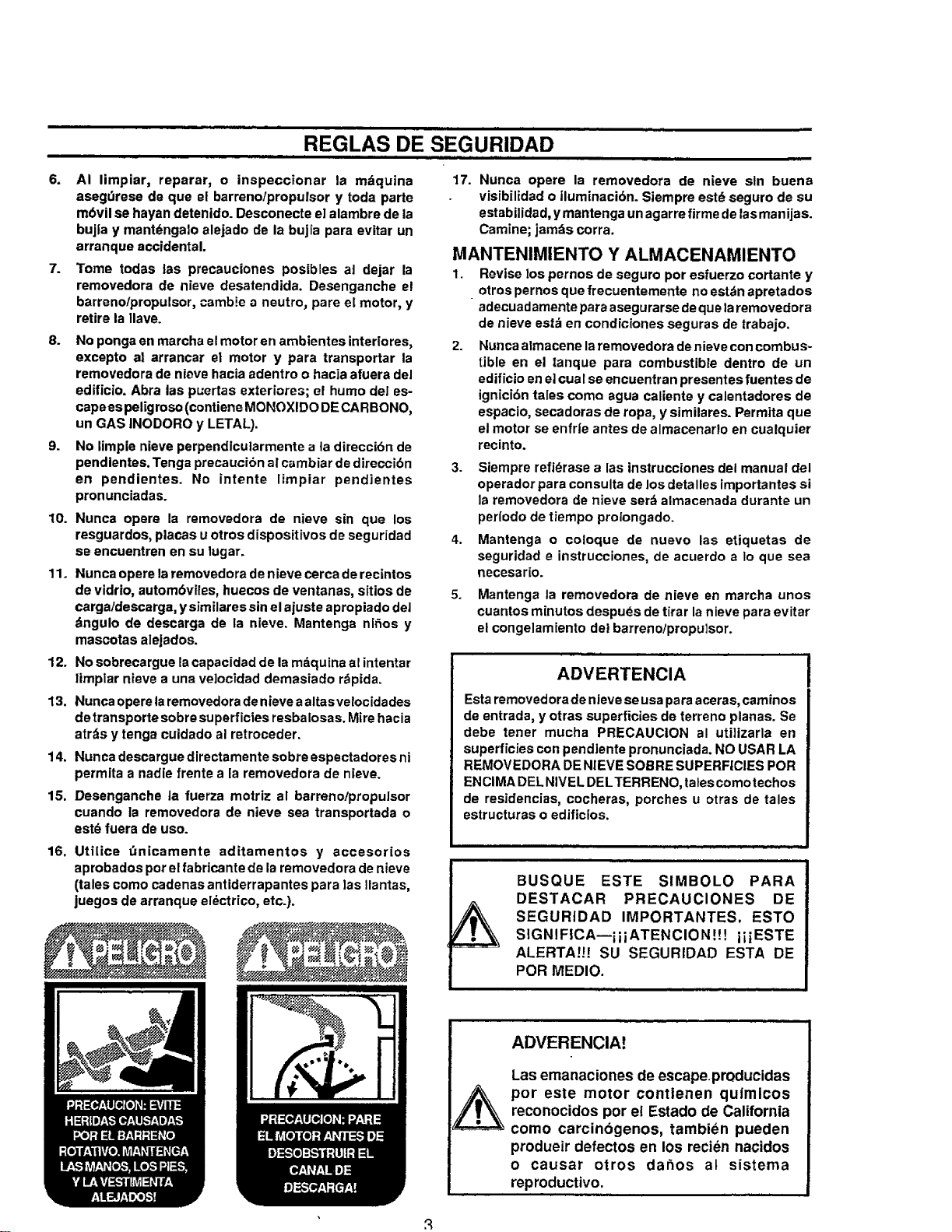
REGLAS DE SEGURIDAD
=|ll ill
6.
7=
AI limpiar, reparar, o inspeccionar la mdquina
asegdrese de que el barreno!propulsor y toda parte
mbvil se hayan detenido. Desconecte e] alambre de la
bujla y mant_ngalo alejado de la bujia para evitar un
arranque accidental.
Tome todas las precauciones posibles at dejar la
removedora de nieve desatendida. Desenganche e!
barrenolpropulsor, camb!e a neutro, pare el motor, y
retire la tlave.
8. No ponga en marcha el motor en ambientes interlores,
excepto a! arrancar el motor y pare transportar la
removedora de nieve hacia adentro o hacia afuera del
edificio. Abra las puertas exteriores; el humo de! es-
capees pel[grose (contiene MONOXIDO DE CARBONO,
un GAS INODORO y LETAL).
9. No limple nieve perpendlcularmente ata direccibn de
pendlentes. Tenga precaucibn al cambiar de direccibn
en pendientes. No intente limpiar pendientes
pronunciadas.
10. Nunca opere la removedora de nieve sin que los
resguardos, places u otros dispositivos de seguridad
se encuentren en su lugar.
11. Nunca opere laremovedora de nieve cerca de recintos
de vidrio, autom6viles, huecos de ventanas, sitios de
carga/descarga, y similares sin el ajuste apropiado del
dngulo de descarga de la nieve. Mantenga nir_os y
mascotas alejados.
12. No sobrecargue la capacidad de la mdquina al intentar
ltmpiar nieve a una ve]ocidad demasiado rdpida.
13. Nunca opere laremovedora de nieve aaltasvelocidades
detransporte sobre superficies resbalosas. Mire hacia
atrds y tenga cuidado al retroceder.
14. Nunca descargue directamente sobre espectadores ni
permlta a nadle frente ala removedora de nieve.
15. Desenganche la fuerza motriz al barrenotpropulsor
cuando la removedora de nieve sea transportada o
est_ fuera de use.
17. Nunca opere la removedora de nieve sin buena
visibilidad o iluminacibn. Siempre estd seguro de su
estabilidad, ymantenga un agarre firme de las manijas.
Camine; jam_s corra.
MANTENIMIENTO Y ALMACENAMIENTO
1. Revise los pernos de seguro per esfuerzo cortante y
otros pernos que frecuentemente no estdn apretados
adecuadamente pare asegurarse de que laremovedora
de nieve esta en condiciones seguras de trabajo.
2. Nunca a]macene laremovedora de nieve con combus-
tible en el tanque para combustible dentro de un
edificto en el cual se encuentran presentes fuentes de
ignici6n tales come ague caliente y calentadores de
espacio, secadoras de ropa, y similares. Permita que
el motor se enfrie antes de almacenario en cualquier
recinto.
3. Siempre refi_rase alas instrucciones del manual del
operador para consulta de los detalles importantes si
la removedora de nieve serd almacenada durante un
per(ode de tiempo prolongado.
4. Mantenga o coloque de nuevo las etiquetas de
seguridad e instrucciones, de acuerdo a Io que sea
necesar[o.
5. Mantenga la removedora de nieve en marcha unos
cuantos minutes despuds de tirar la nieve pare evitar
el congelamiento del barreno/propu]sor.
ADVERTENCIA
Esta removedera de nievese usa para aceras, caminos
de entrada, y otras superficies de terreno planas. Se
debe tener mucha PRECAUCION al utilizarla en
superficies con pendiente pronunciada. NO USAR LA
REMOVEDORA DE NIEVE SOBRE SUPERFICIES POR
ENCIMA DELNIVEL DELTERRENO, talescomotechos
de residencias, cocheras, porches u otras de tales
estructuras o edificios.
16,
Utilice _nicamente aditamentos y accesor[os
aprobados per el fabricante de laremovedora de nieve
(tales come cadenas antiderrapantes para ]as Ilantas,
juegos de arranque el_ctrico, etc.).
__" _ _:_ _ _" i
&
BUSQUE ESTE SIMBOLO PARA
DESTACAR PRECAUCIONES DE
SEGURIDAD IMPORTANTES. ESTO
SIGNIFICA--]ii ATENCION !!! iiiESTE
ALERTA!!! SU SEGURIDAD ESTA DE
POR MEDIO.
ADVERENCIA!
Las emanaciones de escapepmducidas
por este motor contienen quimicos
reconocidos per el Estado de California
come carcinbgenos, tambien pueden
produeir defectos en los recien nacidos
o causer otros dar_os al sistema
reproductive.
FELICITAClONES en sucomprade una Removedorade nieve
Craftsman de SEARS. Esta ha sido disehada y fabricada
usandot_cnicas de ingenieda parabrindarle laconfiabilidady
rendimientom_s altos posibles.
En el caso de que experimente cualqui'_rproblema que no
pueda remediarf&cilmente,porfavor p6ngase en contactocon
su CentroiDepartamento de servicio SEARS mrs cercano.
SEARS tiene t_cnicos competentes, capacitados asf como
tambi6n las herramientas adecuadas para brindar servicio de
mantenimiento o reparar esta unidad.
For favor lea y guarde este manual. Las instrucciones le
permitir_n efectuar el montaje y dar mantenim_ento a [a
removedora de nieve apropiadamente. Siempre observe ]as
"REGLAS DE SEGURIDAD."
NUMERO
DE MODELO536.684780
NUMERO
DE SERIE"
FECHA DE
COMPRA'
.OSNUMEROS DE MODELOY DE SERIE SEENCUENTRAI_
-NLA CALCOMANIA ADHERIDA A LA PARTE POSTERIOF
)EL ALOJAMIENTO DE LA REMOVEDORA DE NIEVE.
SERECOMIEN DAREGISTRA REL NUMERO DESERIE
Y LA FECHA DE COMPRA Y GUARDARLOS EN UN
LUGAR SEGURO PARA REFERENCIA FUTURA.
RESPONSABILIDADES DEL CLIENTE
@ Leer y observar ]as reglas de segundad.
@ Seguir un programaregular para el mantenrm_ento, cuido
y uso de la removedorade n!eve.
@ Seguir las instrucciones bajo las secciones
"Responsabilidades del cliente" y "Almacenarniento"
de este manual del propietano.
ESPECIFICACIONES DEL PRODUCTO
CABALLOS DE FUERZA: 5CV
DESPLAZAMIENTO: 12.04
pulg. c,3bicas
CAPACIDAD DE GASOLINA: 2 cuartos,
Sin plomo
ACEITE (capacidad de 21 onzas) : 5W - 30
BUJIA : Champion
(ENTREHIERRO .030 pulg.) RJ19LM
i
HOLGURA DE VALYLAS: Entrada: .010 pulg
Escape: .010 pulc
CONTRATO DE MANTENIMIENTO
Se disponede unContrato demantenimiento de SEARS para
esteproducto.P6ngase en contactoconlaTiendaSEARS m_s
cercana para obtener informaci6ndetallada,
GARANTIA LIMITADA DE DO ANOS SOBRE LA
REMOVEDORA DE NIEVE CRAFTSMAN
Durante dos aSos a partirde la fecha de compra, cuando esta Removedora de nieve Craftsman sea mantenida, lubricada y
afinada de acuerdo con las instrucciones en el manual del propietario, SEARS reparar&, sin recargo alguno, cualquler defecto
en materiales y mano de obra.
Siesta Removedora de nieve Craftsman se usa para propbsitos comerciales odearrendamiento, esta garantia esv&lidadurante
90 dfas a partir de la fecha de compra.
Esta gar_ntfa no cubre Io siguiente:
@ Elemento.s fungibles los cuales se gastan durante el uso normal, tales come bujias, correas de transmlsion y clavllas cre
seguro por esfuerzo cortante.
@ Reparaciones necesarias debido al abuso o negligeneia del operador, incfuyendo cigSefiales doblados y la falta de
mantenimientodel equipo de acuerdo con las instrucciones contenidas en e! manual de] propietario.
EL SERVICIO DE GARANTIA SE PUEDE OBTENER AL DEVOLVER LA REMOVEDORA DE NIEVE CRAFTSMAN AL
CENTRO/DEPARTAMENTO DE SERVICIO SEARS MAS CERCANO EN LOS ESTADOS UNIDOS. ESTA GARANTIA ES
VALIDA SOLO CUANDO ESTE PRODUCTO SEA USADO EN LOS ESTADOS UNIDOS.
Esta garant{a feotorga derechos legales especificos, yasimis mo esposible que tenga otros derechos los cuares varian de estado
a estado.
SEARS, ROEBUCK AND CO. D/817WA, HOFFMAN ESTATES, IL 60!79
........... ill|
TABLA DE CONTENIDOS
REGLAS DE SEGURIDAD ........................ 2,3
ESPECIFICAClONES DEL PRODUCTO ..... 4
RESPONSABILIDADES DEL CLIENTE .........
............................................................ 4,16-17
GARANTIA .................................................... 4
TABLA DE CONTENIDOS ............................ 5
INDICE .......................................................... 5
MONTAJE .................................................. 6-9
OPE RACION ......................................... 10-15
SERVlCIO YAJUSTES ..... 18=21
ALMACENAMIENTO .................................. 22
SOLUCION DE PROBLEMAS .................... 23
PEDIDOiSERVICIO DE PIEZAS ................ 24
INDICE
A
MontaJe:
Conjunto delcig_efial ...................... 8
Listeade revision............................. 9
Para Montar la Removedora de Nieve
......................................................... 9
Herramientas para montaje ............. 6
Desempaquetado ............................ 7
....................................................... 19
C
Cigfefial:
Montaje ............................................ 8
OperaciSn ...................................... 11
Responsabilidades del cliente4,16-17
Contrato .......................................... 4
Eje del barreno.............................. 17
Motor ............................................. 17
Recomendaciones generafes ........ 16
D
Desviador, canal de descarga de nieve
......................................................... 11
E
Motor:
Control ............................ 10,11,!3,14
Tapadera del aceite.................. 12,17
Cambio de aceite ........................... 17
Nivel de aceite .......................... 12,17
-ripode aceite ...................... 4, 12, 17
Almacenamiento............................ 22
F
Combustible, tipo ................... 4, 12, 17
Combustible, almacenamiento ... 12, 22
H
Manija, superiore inferior................ 7,8
Eje de hexagonal y engranajes ........ !7
I
Llave de ignici6n ............... 10,11,13.14
L
Palancas:
Embrague propulsor del barreno .......
............................... 7, 9, 10,11,12, 17
Extrangulador ................. 10,11,13,14
Control de la acereraci6n.. 10.1!, 13,14
Lubrlcacidn:
Eje de del barreno ......................... 17
Motor ................................... 12,17,22
Table .............................................. 16
O
Acelte:
Motor ........................................ 12,17
Crima extremadamente frio ...... 12,17
Aimacenamiento ............................ 27
Tipo ....................................... 4, 12.17
Operaci6n:
Controles delm otor........ 10,11,13,14
Operaci6n de la removedora de nieve
................................................. 10-12
Arran cluedel motor:
Arranquedel motor, el_ctrico ........ 13
Arranque de[ motor, retroceso....... I4
Controles de la removedora de nieve
.................. ;.............................. 10-12
P
Boton cebo ........................ 10,11;13,14
R
Reparaci6n/Piezas de reemplazo ........
(yea englais) ............................. 23-31
S
Reglas de seguridad .................... 2, 3
Servicio y ajustes:
Perno de segurided por esfuerzo
cortantedel barreno ...................... 20
Correas .................................... 18, 19
Guia de correa ............................... 19
Reempiazos de correa .................. 19
Cable ..................................... 7, 9, 18
Carburador .............................. 20, 22
Bujia .............................................. 21
Especificaciones .............................. 4
Parando la Removedora de nieve. 11
Caja de envio .............................. 6, 7
Almacenamiento ........................... 22
Simbolos ...................................... 11
W
Garantla.............................................4
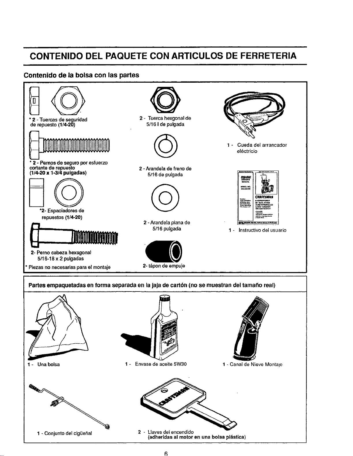
i
CONTENIDO DEL PAQUETE CON ARTICULOS DE FERRETERIA
Contenido de la bolsa con las partes
* 2 - Tuercas de seguridad
de repuesto (1/4-20)
* 2 - Pemos de seguro por esfuerzo
cortantede repuesto
(1/4-20 x 1-3t4 pulgadas)
"2- Espaciadores de
repuestos (114-20)
2- Perno cabeza hexagonal
5!16-18 x 2 pulgadas
Piezas no necesarias para el montaje
Q
2 _ Tuerca hexgonal de
5/16 1de pulgada
(_ 1 - Cueda del arrancadore!6ctricio
2 -Arandela de freno de
5!16 de pulgada
¢m_m,i
C_FP,_lillill
==-=u_._'rp,oi
_*,-,.,.! AU=_EU.ED
,p
2 -Arandela plana de
5/16 pulgada 1 - Instructivo del usuario
2- tdponde empuje
Partes empaquetadas en forma separada en lajaja de carton (no se muestran del tamatto real)
1 - Una bolsa 1 - Envase de aceite 5W30
1 - Canal de Nieve Montaje
1 - Conjunto del cigOeSal
2 - Llavesdel encendido
(adheridas al motor an una bolsa pldstica)
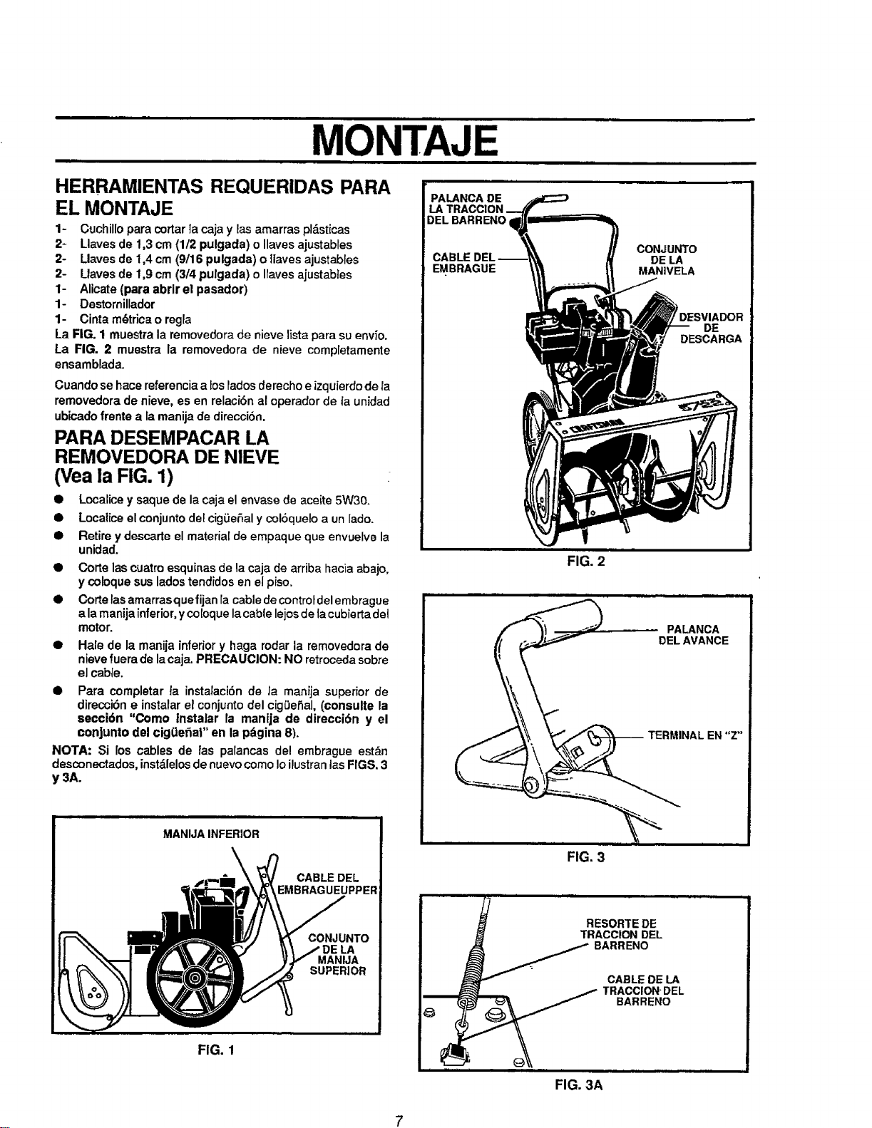
MONTAJ
HERRAMIENTAS REQUERIDAS PARA
EL MONTAJE
1- Cuchillopare cortarIa cajay las amarras pl&sticas
2= Llaves de 1,3 cm (1/2 pulgada) o Ilaves ajustabies
2- Llaves de 1,4 cm (9/16 pulgada) o tlaves ajustables
2- Uaves de 1,9 cm (3/4 pulgada) o Iravesajustables
1- Alicate (para abrir el pasador)
1- Destomillador
1- Cinta m_trica o regla
La FIG. 1 muestra la removedorade nieve lista para su env_o.
La FIG. 2 muestra la removedora de nieve completamente
ensamblada.
Cuando se hace referenciaa Eosrados derecho e izquierdo de la
removedora de nieve, es en relaci6n al operador de ta unidad
ubicadofrente ala manija de direcci6n.
PARA DESEMPACAR LA
REMOVEDORA DE NIEVE
(Vea la FIG. 1)
• Localice ysaque de la caja el envase de aceite 5W30.
• Localice elconjuntodel cig0eSal y col6quelo a un lado.
• Retire y descarte el materialde empaque que envuelve la
unidad.
• Corte las cuatroesquinas de la caja de arriba hacia abajo,
y coloque sus lados tendidos en el piso.
• Corte las amarrasquefijan ra cable de controtdel embrague
ala manUainferior, y coEoquela cable lejos de lacubierta del
motor.
Hale de la manija inferior y haga rodar la removedora de
nievefuera de la caja. PRECAUCION: NO retroceda sobre
el cabte.
• Para completar ta instalaciSn de Ja manija superior de
direcci6n e instalar el conjunto del cig0eSal, (consulte la
secci6n "Como instalar la manija de direcci0n y el
conjunto del cig(Jelial" en la pdgina 8).
NOTA: Si los cables de /as palancas de! embrague est&n
desconectados,instdlelosde nuevocomo Ioilustranlas FIGS. 3
y 3A.
PALANCA DE
LA
DEL BARRENO
CON.JUNTO
CABLE DE LA
EMBRAGUE MANIVELA
FIG. 2
MANIJAINFERIOR
\
FIG. 1
CABLE DEL
EMBRAGUEUPPER
CONJUNTO
LA
MANIJA
SUPERIOR
FIG. 3
j RESORTEDE
TRACCIONDEL
j BARRENO
CABLEDE LA
FIG. 3A
PDESVIADOR
DE
DESCARGA
PALANCA
DELAVANCE
-- TERMINAL EN "Z"
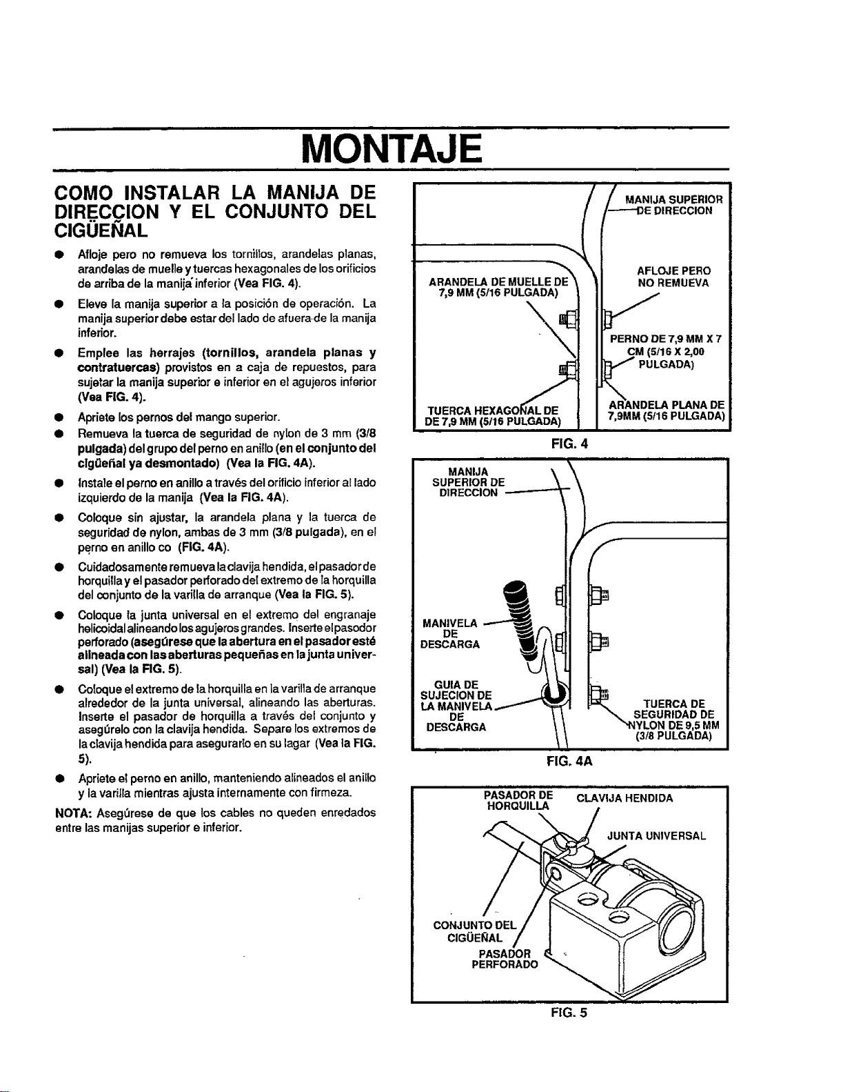
' MONTAjE
COMO INSTALAR LA MANIJA DE
DIR.E.CClON Y EL CONJUNTO DEL
CIGUENAL
• Afloje pero no remueva los torniltos, arandelas planas,
arandelas de muelle y tuercas hexagonales de los orificios
de arriba de la manija'inferior (Vea FIG. 4).
• Eleve la manija superior a la posici6n de operaciSn. La
manija superiordebe estar del lado de afuera-de la manija
inferior.
Emplee las herrajes (tornillos, arandela planas y
contratuerca$) provistos en a caja de repuestos, pare
sujetar la manija superior e inferior en el agujeros inferior
(Vea RG. 4).
Apriete los pernosdel mango superior.
Remueva la tuema de seguridad de nyion de 3 mm (3/8
pulgada) del grupodel pemo en anillo (en elconjunto del
clg0efial ya desmontado) (Vea la FIG. 4A).
|nstale elperno en anilloa travL_sdel orificioinferioral lado
izquierdode la manija (Vea la RG, 4A).
Coloque sin ajustar, la arandela plana y la tuerca de
seguridad de nylon, ambas de 3 mm (3/8 pulgada), en el
perno en anillo co (FIG. 4A).
Cuidadosamente rem uevalaclavija hendida, el pasador de
horquilla y elpasador perforado det extremo de TahorquUla
del conjunto de la vat|lie de arranque (Yea la FIG. 5).
Coloque _ajunta universal en el extremo de! engranaje
helicoidal alineando losagujeros grandes. Inserteelpasodor
perforado(aseg_rese que laabertura en elpasador estd
allneada con las aberturas peque_as en lajunta univer-
sal) (Vea la RG. 5).
• Coloque e!extremo de tahorquillaen tavarilla de arranque
alrededor de la junta universal, alineando las aberturas.
Inserte el pasador de horquilla a trav6s del conjunto y
asegOrelo con laclavija hendida. Separe los extremosde
laclavija hendida pare asegurar_oensu lagar (Vea la FIG.
5).
• Apdete e_perno en anillo,manteniendo alineadosel anillo
y la varilla mientras ajusta internamente con firmeza.
NOTA: Aseg_rese de que los cables no queden enredados
entrelas manijas superior e inferior.
MANIJA SUPERIOR
DIRECCION
ARANDELADEMUELLE
7,9 MM(5/16 PULGADA)
\,
AFLOJE PERO
NO REMUEVA
PERNO DE 7,9 MM X 7
(5t16 X 2,00
PULGADA)
TUERCA
DE 7,9 MM
MANIJA \
SUPERIOR DE
DIRECCION -----------=
MANIVELA
DE
DESCARGA
GUIADE
SUJECIONDE
DE
DESCARGA
FIG. 4
)
DE
7,gMM (5/16 PULGADA)
TUERCA DE
SEGURIDAD DE
DE 9,5 MM
3/8 PULGADA)
FIG, 4A
PASADOR DE
HORQUILLA
CLAVIJA HENDIDA
JUNTA UNIVERSAL
CONJUNTO DEL
CIGOE_AL
PASADOR
PERFORADO
FIG. 5
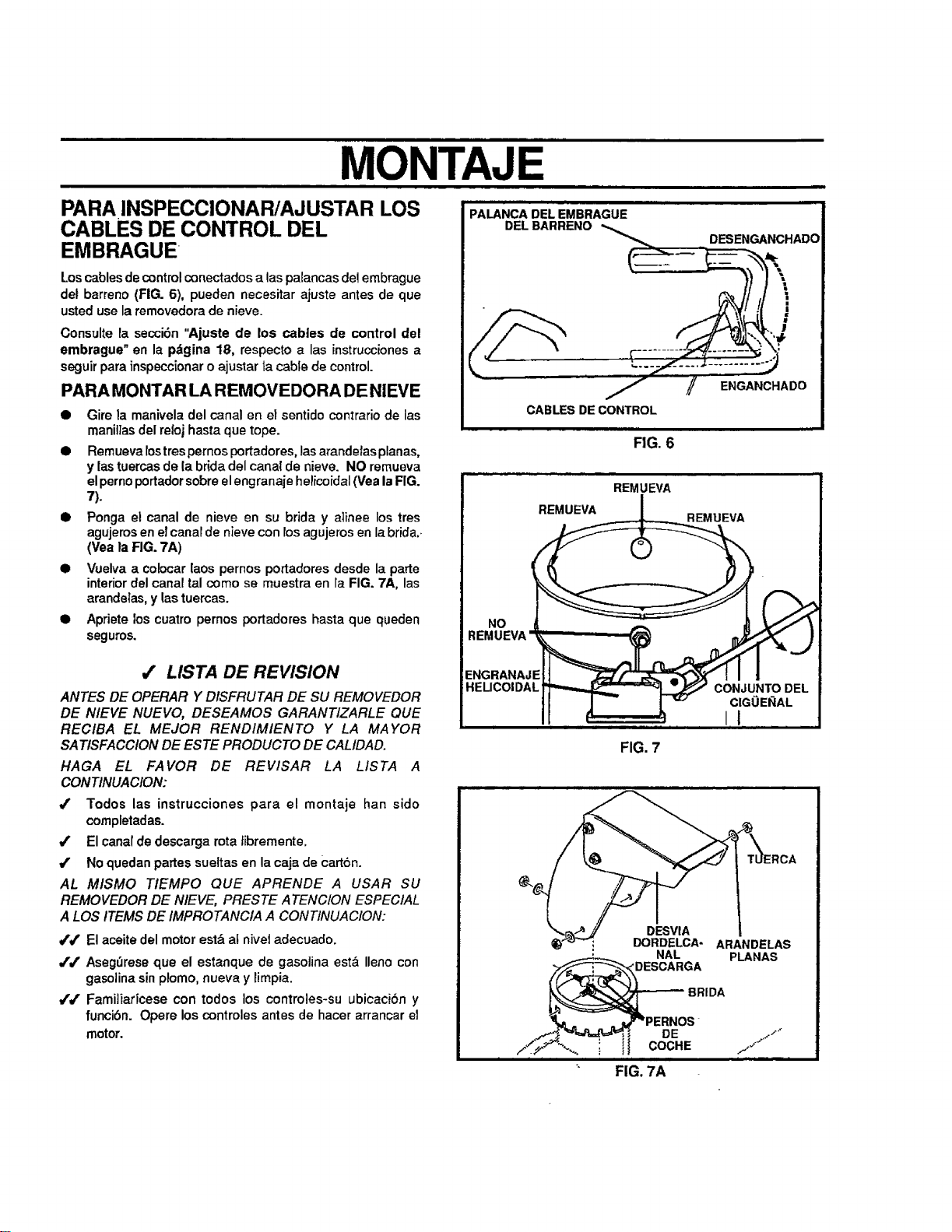
MONTAJ
PALANCADELEMBRAGUE .........
PARA INSPECCIONAR/AJUSTAR LOS
CABLES DE CONTROL DEL
EMBRAGUE
Loscablesde control conectados alas palancas del embrague
del barreno (FIG. 6), pueden necesitar ajuste antes de que
usted use la removedora de nieve.
Consulte la secci6n "Ajuste de los cables de control del
embrague" en la pdgina 18, respecto alas instruccionesa
seguir para inspeccionar o ajustar ta cable de control.
PARA MONTAR LA REMOVEDORA DE NIEVE
• Gire la manivela del canal en el sentido contrario de las
manillas del relojhasta que tope.
• Remueva rostres pernos portadores, lasarandetas planas,
y las tuercas de la brida del canal de nieve. NO remueva
el pernoportador sobre el engranaje helicoidal (Vea laFIG.
7).
• Ponga el canal de nieve en su brida y atinee los tres
agujeros en el canar de nieve con rosagujeros en la brida..
(Yea la FIG. 7A)
• Vuelva a co!ocar laos pernos portadores desde la parte
interior del canal tal como se muestra en la FIG. 7A, las
arandetas, y las tuercas.
• Apriete los cuatro pemos portadores hasta que queden
seguros.
/ LISTA DE REVISION
ANTES DE OPERAR Y DISFRUTAR DE SU REMOVEDOR
DE NIEVE NUEVO, DESEAMOS GARANTIZARLE QUE
RECIBA EL MEJOR RENDIMIENTO Y LA MAYOR
SATISFACCION DE ESTE PRODUCTO DE CALIDAD.
HAGA EL FAVOR DE REVlSAR LA LIS TA A
CONTINUACION:
_' Todos las [nstrucciones para el montaje ban sido
completadas.
#' El canalde descarga rota tibremente.
4' No quedan partes sueltas en la caja de carton.
AL M/SMO TIEMPO QUE APRENDE A USAR SU
REMOVEDOR DE N/EVE, PRESTE ATENC/ON ESPECIAL
A LOS ITEMS DE/MPROTANCIA A CONTINUACION:
V'/ El aceite del motor est&a[ nivei adecuado.
JJ AsegOrese que el estanque de gasolina est& Ileno con
gasolinasinplomo, nueva y limpia.
JJ FamiJiaricese con todos los controles-su ubicaciSn y
funcibn. Opere los controles antes de hacer arrancar el
motor.
FIG. 6
REMUEVA
REMUEVA REMUEVA
°o @
REMUEVA
EHGRANAJEJ1 _/_-_"_"_ I I
HELICOIDAL " CON,JUNTODEL
II 13
FIG. 7
DESVIA
DORDELCA- ARANDELAS
NAL PLANAS
DESCARGA
BRIDA
DE
it COCHE
FIG. 7A
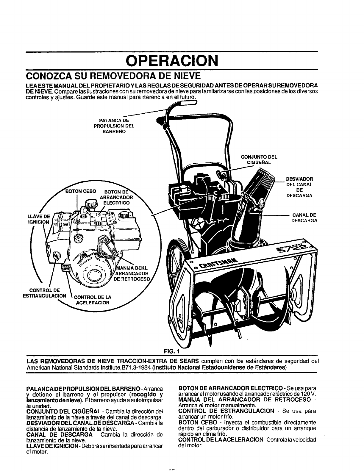
OPERACION
CONOZCA SU REMOVEDORA DE NIEVE
LEA ESTE MANUAL DEL PROPIETARIO Y LAS REGLAS DESEGURIDAD ANTES DEOPERAR SU REMOVEDORA
DE NIEVE. Compare lasilustracionesconsuremovedoradenieveparafamilarizarse conlasposicionesde losdiversos
controlesy ajustes. Guarde este manual para rferencia en el futuro.
PALANCA DE
PROPULSION DEL
BARRENO
CONJUNTO DEL
CIGUE_AL
LLAVE DE
IGNICION
I
BOTON
ELECTRICO
DESVIADOR
DELCANAL
DE
DESCARGA
CANALDE
DESCARGA
\
CONTROL DE
ESTRANGULACION
_ANIJA DEKL
_RRANCADOR
CONTROL DE LA
ACELERACION
DE RETROCESO
FIG. 1
LAS REMOVEDORAS DE NIEVE TRACClON-EXTRA DE SEARS cumplen con los est_ndares de seguridaddel
AmericanNationalStandardsInstitute,B71.3-1984 (Instituto National Estadounidense de Estdndares).
PALANCA DEPROPULSION DEL BARRENO- Arranca
y detiene el barreno y el propulsor (recogido y
lanzamientode nieve). Elbarrenoayudaa autoimpulsar
la unidad.
CONJUNTO DEL CIGOEI_IAL- Cambiala direcci6n del
lanzamientode la nievea trav_sdel canal de descarga.
DESVIADOR DEL CANAL DE DESCARGA - Cambia la
distanciade lanzamientode la nieve.
CANAL DE DESCARGA - Cambia la direcci6n de
lanzamientode la nieve.
LLAVE DEIGNICION- Deber&set insertada paraarrancar
el motor.
BOTON DEARRANCADOR ELECTRICO - Se usapara
arrancar el motor usando el arrancado rel_ctricode 120 V.
MANIJA DEL ARRANCADOR DE RETROCESO -
Arrancael motormanualmente.
CONTROL DE ESTRANGULACION - Se usa para
arrancarun motorfifo.
BOTON CEBO - Inyecta el combustible dJrectamente
dentro del carburador o distribuidorpara un arranque
r&pidoenclimafr[o.
CONTROLDELAACELERACION-Controlalave[ocidad
del motor.
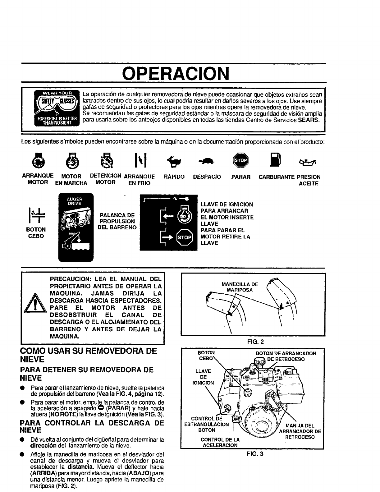
OPERACION
La operaci6nde cualquier removedora, de nieve puede ocasionarque objetosextrahos sean
lanzados dentro de sus ojos, lo cual podrfa resultar en dahos severos a los ojos. Use siempre
galas de seguridad o protectores para los ojos mientras opere la removedora de nieve.
Se recomiendan las gafas de seguridad est&ndar o la m,_scara de seguridad de visi6n amplia
para usarla sobre los anteojos disponibles en todas las tiendas Centro de Servicios SEARS.
Los siguientes sfmbo!ospueden encontrarse sobre la m_quina o en la documentaci6n proporcionada con elproducto:
ARRANQUE MOTOR DETENCIONARRANQUE RAP|DO
MOTOR ENMARCHA MOTOR ENFRIO
DESPACIO PARAR CARBURANTEPRESION
ACEITE
BOTON
CEBO
PALANCA DE
PROPULSION
DEL BARRENO
LLAVE DE IGNICION
PARA ARRANCAR
EL MOTOR INSERTE
LLAVE
PARA PARAR EL
MOTOR RETIRE LA
LLAVE
PRECAUClON: LEA EL MANUAL DEL
PROPIETARIO ANTES DE OPERAR LA
MAQUINA. JAMAS DIRIJA LA
DESCARGA HASClA ESPECTADORES.
PARE EL MOTOR ANTES DE
DESOBSTRUIR EL CANAL DE
DESCARGA O EL ALOJAMIENATO DEL,
BARRENO Y ANTES DE DEJAR LA
MAQUINA.
COMO USAR SU REMOVEDORA DE
NIEVE
PARA DETENER SU REMOVEDORA DE
NIEVE
• Paraparar el lanzamiento de nieve, suelte la palanca
de propulsi6n del barreno (Yea la FIG. 4, p,'.'tgina12).
• Para parar el motor, empuj._,lapalanca de control de
la aceleraci6n a apagado i_ (PARAR) y hale hacia
afuera (NOROTE) la Ilavede ignici6n (Vea la FIG. 3).
PARA CONTROLAR LA DESCARGA DE
NIEVE
• Dd vueltaal conjunto del cig0ehalpara determinar la
direcci6n del lanzamiento de la nieve.
Afloje la manecilla de mariposa en el desviador del
canal de descarga y mueva el desviador para
establecer la distancia. Mueva el deflector hacia
(ARRIBA) para mayor distancia, hacia (ABAJO) para
una distancia menor. Luego apriete la manecilla de
mariposa (FIG. 2).
MANECILLA DE
MARIPOSA
BOTON
FIG. 2
BOTON DE ARRANCADOR
DE RETROCESO
LLAVE
DE
IGNICION
\
CONTROLDE
ESTRANGULACION
BOTON
CONTROL DE LA
ACELERACION
FIG. 3
MANIJA DEL
ARRANCADOR DE
RETROCESO
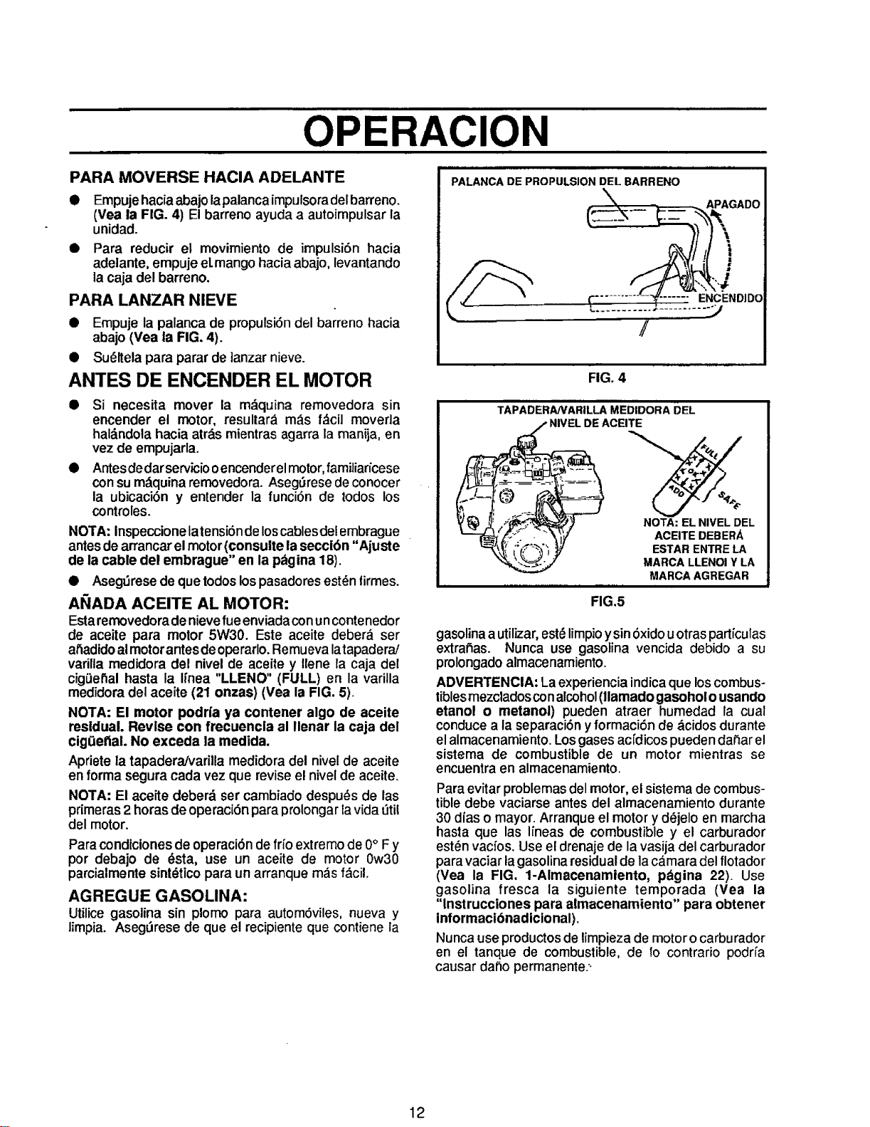
OPERAClON
PARA MOVERSE HACIA ADELANTE
Empuje hacia abajo lapalancaimpulsora del barreno.
(Vea la FIG. 4) El barreno ayuda a autoimpulsar la
unidad.
Para reducir el movimiento de impulsi6n hacia
adelante, empuje el.mango hacia abajo, levantando
la caja del barreno.
PARA LANZAR NIEVE
• Empuje la palanca de propulsi6n del barreno hacia
abajo (Yea ia FIG. 4).
• Su_ltela para parar de ]anzar nieve.
ANTES DE ENGENDER EL MOTOR
• Si necesita mover la m_quina removedora sin
enGender el motor, resultar__ m_s f&cil moverla
haldndola hacia atr_.smientras agarra la manija, en
vez de empujarla.
• Antes dedar serviciooenGenderelmotor,familiar/cese
con sum_lquinaremovedora. Aseg_rese de conocer
la ubicaci6n y entender la funci6n de todos los
controles.
NOTA: Inspeccione latensi6n de loscablesde!embrague
antesde arrancar elmotor (consuite lasecci6n "Ajuste
de la cable del embrague" en la p_gina 18).
• Aseg_rese de quetodos lospasadoresest_ntirmes.
AI;/ADA ACEITE AL MOTOR:
Estaremovedoradenievefueenviada con uncontenedor
de aceite para motor 5W30. Este aceite deber_ ser
al_adidoalmotorantes de operarlo.Remueva latapadera/
varilla medidora Gel nivel de aceite y Ilene la caja del
cigOenalhasta la Ifnea "LLENO" (FULL) en la varilla
medidoradel aceite (21 onzas) (Vea la FIG. 5).
NOTA: El motor podda ya contener algo de aceite
residual. Revise con frecuencla al Ilenar la caja del
cig(ietial. No exceda la medida.
Apriete la tapadera/varilla medidora del nivelde aceite
enforma segura cada vez que revise el nivelde aceite.
NOTA: El aceite deberd set cambiado despu_s de las
primeras 2 horas de operaci6n para prolongar lavida t_til
del motor.
Paracondicionesde operaci6nde frfo extremo de 0° Fy
por debajo de _sta, use un aceite de motor 0w30
parcialmentesint_tico para un arranque m_s f_cil.
AGREGUE GASOLINA:
Utilice gasolina sin plomo para autom6viles, nueva y
limpia. Aseg_rese de que el recipiente que contiene la
PALANCA DE PROPULSION DEL BARRENO
\
, APAGADO
[I J
(-........ _CENDIDO
/
FIG. 4
TAPADERANARILLA MEDIDORA DEL
/ NIVEL DE ACEITE
NOTA: EL NIVEL DEL
ACEITE DEBERA
ESTAR ENTRE LA
MARCA LLENOI Y LA
MARCA AGREGAR
FIG.5
gasolina a utilizar, est_ limpioy sin6xido u otrasparticulas
extra,as. Nunca use gasolina vencida debido a su
prolongado almacenamiento.
ADVERTENClA: La experiencia indica que loscombus-
tiblesmezclados conalcohol(llamado gasohol ousando
etanol o metanoi) pueden atraer humedad la cual
conducea la separaci6n y formaci6n de acidos durante
elalmacenamiento. Losgasesacidicos pueden da_ar el
sistema de combustible de un motor mientras se
encuentra en almacenamiento.
Para evitar problemas del motor, el sistema de combus-
tible debe vaciarse antes del almacenamiento durante
30 dias o mayor. Arranque el motor y dejelo en marcha
hasta que las Iineas de combustible y el carburador
esten vacfos. Use el drenaje de la vasija del carburador
para vaciar la gasolina residual de la camara del flotador
(Vea la FIG. 1-Almacenamiento, p_gina 22). Use
gasolina fresca la siguiente temporada (Vea la
"lnstrucciones para almacenamiento" para obtener
informacibnadicional).
Nunca use productos de limpieza de motor o carburador
en el tanque de combustible, de fo contrario poclria
causar daSo permanente..
12
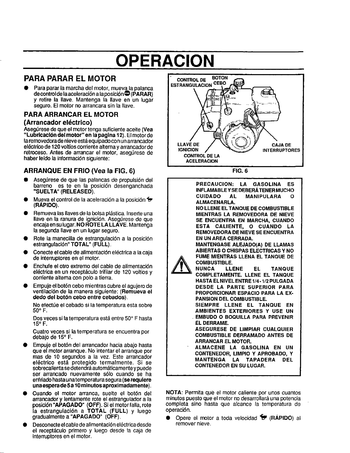
OPERACION
PARA PARAR EL MOTOR
Para parar la marcha del motor, muev_a palanca
decontrolde laaceleraci6na laposici6n _ (PARAR)
y retire la Ilave. Mantenga la Ilave en un lugar
seguro.El motorno arrancara sin la llave.
PARA ARRANCAR EL MOTOR
(Arrancador el_ctrico)
AsegSresedeque elmotortenga suticienteaceite(Vea
"Lubr|caclbn del motor" en lapagina 12). El motorde
qarernovedoradenieveest,,equipado conunarrancador
el_trico de 120voltios corriente alterna y arrancador de
retroceso. Antes de arrancar el motor, aseg_rese de
haber lefdo la informaci6n siguiente:
ARRANQUE EN FR]O (Vea la FIG. 6)
• Aseg_rese de que las palancas de propulsi6n del
barreno es teen ta posici6n desenganchada
"SUELTA" (RELEASED).
• Mueva elcontrol de laaceleraci6n a la posici6n ,rm
(RAPIDO).
• RemuevalasIlavesde labolsa pl_stica.Inserte una
Ilave en la ranura de ignici6n.AsegL_resede que
encajaensulugar.NO ROTE LA LLAVE. Mantenga
la segunda Ilaveen un lugarseguro.
• Rote la manecilla de estrangulaci6na la posici6n
estrangulaci6n"TOTAL" (FULL).
• Conecteelcable de alimentaci6nel6ctricaa lacaja
de interruptoresen el motor.
• Enchufeel otto extremo del cable de alimentaci6n
el_ctricaen un recept&culotrifilarde 120 voltiosy
corrientealtema con poloa tierra.
• Empujeelbot6ncebo mientras cubreel agujero de
ventilaci6nde la manera siguiente: (Remueva el
dedo del botbn cebo entre cebados).
No efect_e el cebado si la temperatura esta sobre
50<'F.
Dos veces si la temperatura est_ entre 50° F hasta
15('F.
Cuatro veces si la temperatura se encuentra per
debajo de 15° F.
• Empuje el botSn del arrancador hacia abajo hasta
que el motor arranque. No intentar el arranque pot
mas de 10 segundos a ta vez. Este arrancador
el_ctrico est,. protegido termalmente. Si se
sobrecalientasedetendr&autom_ticamente ypuede
ser arrancado nuevamente s61o cuando se ha
enfriadohasta unatemperatura segura(se requiere
unaespera de5a 10minutos aproximadamente)
• Cuando el motor arranca, suelte el bot6n del
arrancador y lentamente rote el estrangulador a la
posici6n "APAGADO" (OFF). Si el motor falla, rote
la estrangulaci6n a TOTAL (FULL) y luego
gradualmente a "APAGADO" (OFF).
• Desconecteelcable de alimentaci6n et_ctrica desde
el recept_.culo pdmero y luego desde la caja de
interruptores en el motor.
• CONTROL DE BOTON
ESTRANGULACION CE|
LLAVE DE CAJA DE
IGNICION INTERRUPTOR ES
CONTROL DE LA
ACELERACION
FIG. 6
PRECAUCION: LA GASOLINA ES
INFLAMAB LEY SEDEBERA TENER MUCHO
CLIIDADO AL MANIPULARA O
ALMACENARLA.
NO LLENE EL TANQUE DE COMBUSTIBLE
MIENTRAS LA REMOVEDORA DE NIEVE
SE ENCUENTRA EN MARCHA, CUANDO
ESTA CALIENTE, O CUANDO LA
REMOVEDORA DE NIEVE SE ENCUENTRA
EN UN AREA CERRADA.
MANTENGASE ALEJADO(A) DE LLAMAS
ABIERTAS O CHISPAS ELECTRICAS Y NO
FUME MIENTRAS LLENA EL TANQUE DE
COMBUSTIBLE.
NUNCA LLENE EL TANQUE
COMPLETAMENTE. LLENE EL TANQUE
HASTA EL NIVEL ENTRE I/4-1/2 PULGADA
DESDE LA PARTE SUPERIOR PARA
PROPORCIONAR ESPACIO PARA LA EX-
PANSION DEL COMBUSTIBLE.
SIEMPRE LLENE EL TANQUE EN
AMBIENTES EXTERIORES Y USE UN
• EMBUDO O BOQUILLA PARA PREVENIR
EL DERRAME.
ASEGURESE DE LIMPIAR CUALOUIER
COMBUSTIBLE DERRAMADO ANTES DE
ARRANCAR EL MOTOR.
ALMACENE LA GASOLINA EN UN
CONTENEDOR, UMPIO Y APROBADO, Y
MANTENGA LA TAPADERA DEL
CONTENEDOR EN SU LUGAR.
NOTA: Permita que el motor caliente por unos cuantos
minutos puesto que el motor no desarrollara una potencia
completa sino hasta que alcance la temperatura de
operaci6n.
• Opere el motor a toda velocidad _'_ (RAPIDO) al
remover nieve.
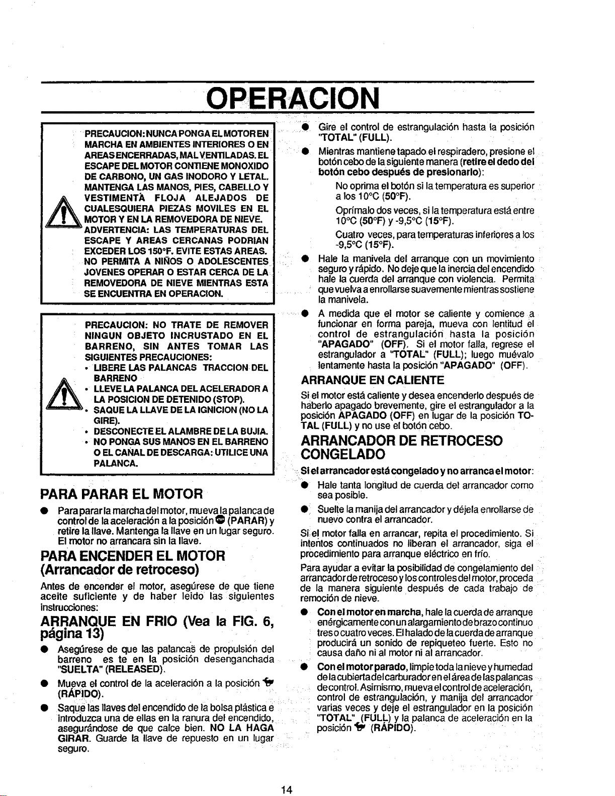
'O
i = =
i Gire el control de estrangulaci6n hasta ia posici6n
" i
_R CONTIF.NEMONOXlDO I
_AS INOOOROY LETALoI
" MANTENGALAS.MANOS, PIES,CABELLOY I
FLOJA ALEJAOOSOEI
_r_ _IA_=E_IIE_A M_S MOVILES EN EL I
E_S CERCANAS PODRIAN J
_°F. EVITEESTASAREAS. !
ADOLESCENTES •
JOVENESOPERARO ESTAR CERCADELA ! _
AREAS ENCERRADAS, MALVENlILADAS. EL
ESCAPE DEL MOTOR CONTIENE MONOXIDO
DE CARBONO, UN GAS INODORO Y LETALo
MANTENGA LAS MANOS, PIES, CABELLO Y
ESCAPE Y AREAS CERCANAS PODRIAN
EXCEDERLOS150°F.EVITEESTASAREAS.
NO PERMITAA NII_OS O ADOLESCENTES
JOVENESOPERARO F.STARCERCADELA
REMOVEDORADE NIEVE MIENTRAS ESTA
SE ENCUENTRAEN
PRECAUCION: NO TRATE DE REMOVER
NINGUN OBJETO INCRUSTADO EN EL
BARRENO, SIN ANTES TOMAR LAS
SIGUIENTESPRECAUCIONES:
• LIBERE I.ASPALANCAS TRACCIONDEL
A BARRENO
. LLEVELAPALANCADELACELERADORA
LA POSICIONDEDETENIDO(STOP).
• SAQUELALLAVEDELAIGNICION(NOLA
GIRE).
• DESCONECTEELALAMBREDELABUJIA.
• NOPONGASUS MANOSENELBARRENO
O ELCANALDEDESCARGA:UTILICEUNA
PALANCA.
PARA PARAR EL MOTOR
• Parapararlamarchadelmotor, muevalapalancade
controlde la aceteraci6n a la posici6n _ (PARAR) y
retire la tlave. Mantenga la Ilave en un lugar seguro.
El motor no arrancara sin la Ilave.
PARA ENGENDER EL MOTOR
(Arrancador de retroceso)
Antes de encender el motor, aseg_rese de que tiene
aceite suficiente y de haber leido las siguientes
instmcciones:
ARRANQUE EN FRIO (Vea la FIG. 6,
pdgina 1,3)
• Aseg_rese de que las palanca_ de propulsi6ndel
"TOTAL" (FULL).
Mientrasmantienetapadoel respiradero,presioneet
bot6ncebodelasiguientemanera (retireeldedo del
botbn cebo despuds de presionarlo):
Nooprimael bot6nsilatemperatura es superior
a los 10°C (50°F).
Oprfmalodosveces,si latemperaturaest_entre
10°C (50°F) y-9,5°C (15°F).
Cuatro veces, para temperaturasinferi0resa los
-9,5°C (15°F).
Hale la manivela det arranque con un movimiento
seguroy rdpido.Nodejeque lainerciadel encendido
hale la cuerda detarranque con violencia. Permita
quevueivaa enrollarsesuavemente mientras sostiene
la manivela.
A medida que el motor se caliente y comiencea
funcionar en forma pareja, mueva con lentitud el
control de estrangulaci6n hasta la posici6n
"APAGADO" (OFF). Si et motorfalla, regrese el
estrangulador a "TOTAL" (FULL); luego mu_valo
, lentamentehastala posici6n"APAGADO" (OFF).
ARRANQUE EN CALIENTE
Siel motorestdcalientey desea encenderlodespu6sde
habedo apagado brevemente, gire el estrangulador a la
posici6n APAGADO (OFF) en lugar de la posici6n TO-
TAL (FULL) y no use el boron cebo.
ARRANCADOR DE RETROCESO
CONGELADO
i _;Stel arrancador estdcongeladoy no arranca elmotor:
• Hale tanta Iongitud de cuerda det arrancador como
sea posible.
e Suelte la manija del arrancador yd6jela enrollarse de
nuevo contra el arrancador.
Siel motor falla en arrancar, repita el procedimiento. Si
intentos continuados no tiberan el arrancador, siga el
procedim!ento para arranque el_ctrico en frfo.
Para ayudar a evitar la posibitidad de congelamiento del
arrancadorde retroceso yloscontroles de!motor, proceda .....
de la manera siguiente despu_s de cada trabajo de
remoci6n de nieve.
• Con elmotoren marcha, hale lacuerdade arranque
en_rgicamentecon unalargamientodebrazocontinuo
tresocuatroveces.Elhaladodelacuerdadearranque
pmducir_ un sonidode repiqueteo tuerte. Esto no
causadar_oni al motorni al arrancador.
barreno es teen la posici6n desenganchada .........
"SUELTA" (RELEASED). • Conel motor parado, limpietoda lanievey humedad
Mueva el controlde la aceleraci6n a la posici6n_ delacubiertadetcarburadorenel_reade laspalancas
.... decontrol.Asimismo, mueva elcontroldeaceleraci6n,
(R_l-!uu).""''*" . control de estrangulaci6n, y manija del arrancador
Saque las llaves del encendido de ta bolsa pldstica e..... varias veces y deje el estrangulador en la posici6n
introduzca una de elias en la ranura det encendido, : ''TOTAL" (FULL) y la palanca de aceleraciSn en la
asegur_ndose de que calce bien. NO LA HAGA .... posiciSn _ (RAPIDO). •
GIRAR. Guarde la Ilave de repuesto en un lugar -
seguro.
14
OPERACION
OPISTAS SOBRE LANZAMIENTO DE
NIEVE
• Para obtener laeficiencia m_.ximadel removedor de
nieve opere el motor a una aceleraciSn total.
Q El lanzamiento de nieve es m&s eficiente si fa
remoci6n de la misma se electra inmediatamente
despu_s de su cafda.
• Para una remoci6n completa de la nieve, traslape
ligeramente cada camino adoptado previamente.
• La nieve deberfa ser descargacla en la direcci6ndel
viento siempre que sea posible.
Si la parte delanterade la removedora de nievetiene
la tendencia de elevarse reduzca la velocidad sobre
elterreno y enganche el sistema de transferencia de
peso.
Despu_s deque se haya completado el lanzamiento
de nieve, permita que el motor se encuentre en
.reposo por unos cuantos minutos, Iocuai derretir_,fa
nieve y hielo acumulado det motor.
Efect.i_eunalimpieza completa de la removedora de
nieve luego de cada uso.
Remueva la acumulaci6n de hielo y nieve y todo
material extrat_oheterog_neo de la removedora de
nieve en su totalidad, y lave con agua (si fuese
posible) para remover toda sal u otras substancias
quimicas. Sequela removedora de nieve.
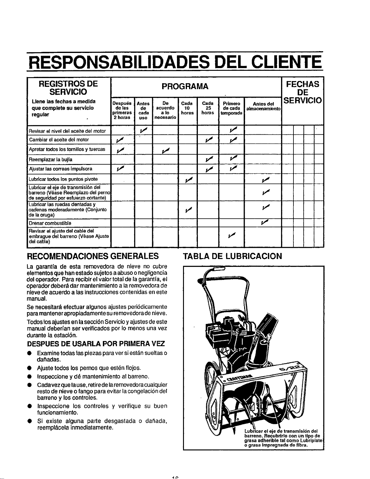
RESPONSABILIDADES DEL CLIENTE
REGISTROS DE
SERVIClO
PROGRAMA
Llene las fechas a medlda Despuds Antes De Cada Cada Primero Antes del
que complete su servicio de las de acuerdo 10 25 de cada almacenamiento
regular primeras cada a Io horas horas temporada
2 horas uso necesario
Revisar el nivel del aceite del motor
CambiaTelaceitedelmotor
Apretartodoslost0rnillosy tuercas
Reemplazarlabujia
Ajustarlascorreasirr_utsora
LubrLcartodoslospuntospivote
Lubricarelejedetransmisi6ndel
barreno(V_aseReemplazodelpernc
deseguridadporesfuerzooortante)
Lubricarlasruedasdentadasy
cadenasmoderadamente(Conjunto
delaoruga)
Drenarcombustible
Revisar el ajuste de! cable del
embrague del barreno (V_ase Ajuste
del cable)
v_
v"
v,' v"
v" v_
v"
ii' v"
ii' v"
11' /I'
v"
v"
II'
FECHAS
DE
SERVICIO
RECOMENDACIONES GENERALES
La garantfa de esta removedora de nieve no cubre
elementosque han estadosujetosa abusoonegligencia
del operador. Para recibirel valortotal de lagarantia, el
operador deberddar mantenimientoa laremovedorade
nievede acuerdo alas instruccionescontenidasen este
manual.
Se necesitard efectuar algunos ajustesperi6dicamente
paramantenerapropiadamentesuremovedoradenieve.
Todoslosajustes en lasecci6n Servicioy ajustes deeste
manualdeber[an ser verificadospot Io menos una vez
durante la estaci6n.
DESPUES DE USARLA POR PRIMERA VEZ
• Examine todas las piezaspara ver si est_,nsueltas o
datiadas.
• Ajuste todos los pernos que estdn flojos.
• Inspeccione y dd mantenimiento al barreno.
• Cadavezquelause, retirede laremovedoracualquier
resto de nieve o fango para evitar Facongelaci6n del
barreno y loscontroles.
• Inspeccione los controles y verifique su buen
funcionamiento.
• Si existe alguna parte desgastada o datiada,
reempl_cela inmediatamente.
TABLA DE LUBRICACION
_e de transmist6n del
barreno, Recubrirfo con un ripe de
grasa adherible tal eomo Lubriplate
o grasa impregnada de fibra.
,, i i i i
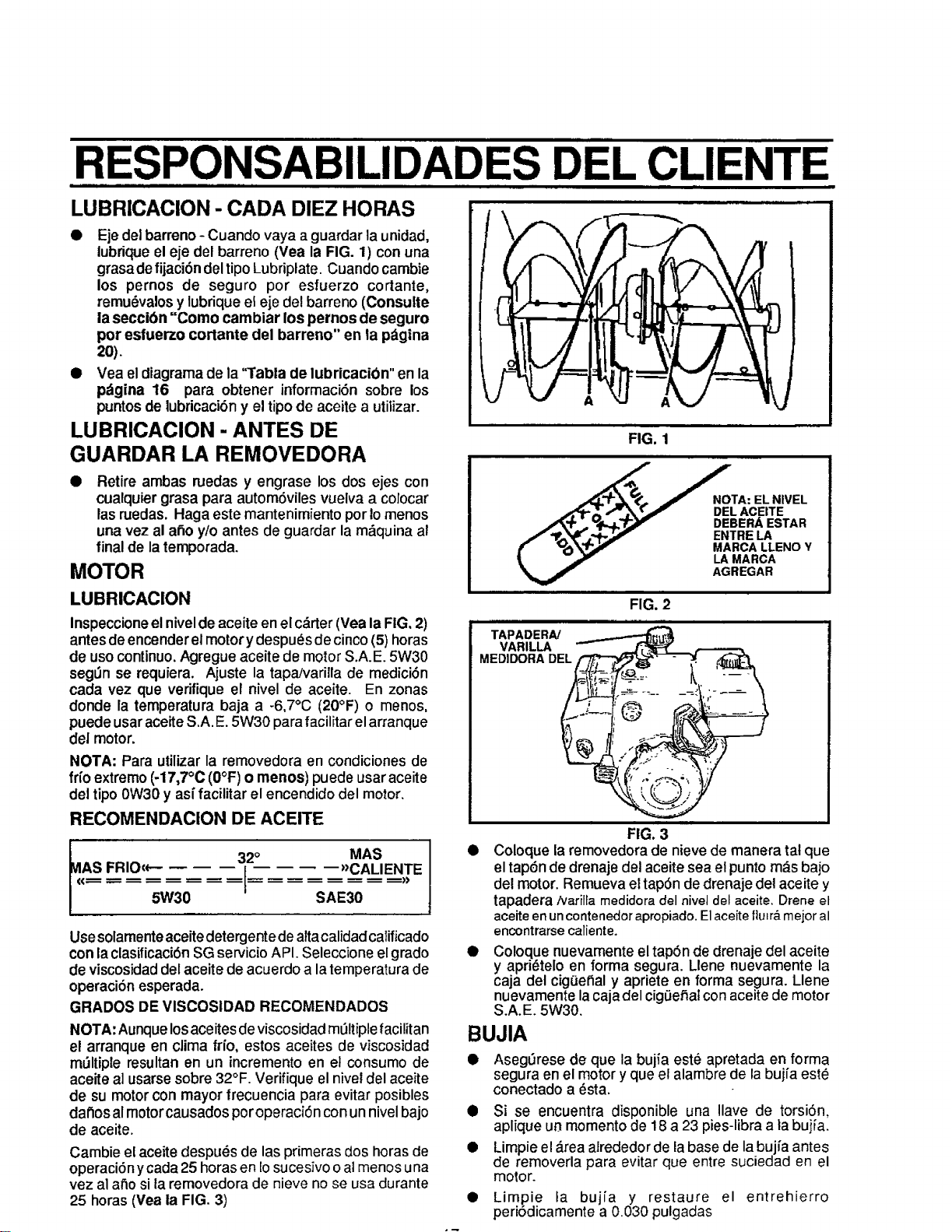
RESPONSABILIDADES D L CLIENTE
LUBRICACION - CADA DIEZ HORAS
• Ejedel barreno - Cuando vaya a guardar launidad,
lubrique el eje del barreno (Yea la FIG. 1) con una
grasa de fijaci6n del tipo Lubriplate. Cuando cambie
los pernos de seguro por esfuerzo cortante,
remu_valos y lubriqueel eje del barreno (Consulte
la seccibn "Como cambiar los pernos de seguro
pot esfuerzo cortante del barreno" en ta pdgina
20).
• Vea el diagrama de la 1"abla de lubricacibn" en la
p_tgina 16 para obtener informaci6n sobre los
puntosde lubricaci6ny el tipode aceite a utilizar.
LUBRICAClON - ANTES DE
GUARDAR LA REMOVEDORA
• Retire ambas ruedas y engrase los dos ejes con
cualquier grasa para autom6viles vuelva a colocar
las ruedas. Haga este mantenimiento por Iomenos
una vez al afio y/o antes de guardar la m_quina al
final de la temporada.
MOTOR
LUBRICACION
Inspeccioneel nivel de aceite en el c&rter (Vea la FIG, 2)
antes de encender el motor ydespu_s de cinco (5) horas
de uso continuo. Agregue aceite de motor S.A.E. 5W30
segOn se requiera. Ajuste la tapa/varilla de medici6n
cada vez que vedfique el nivel de aceite. En zonas
donde la temperatura baja a -6,7°C (20°F) o menos,
puede usar aceite S,A.E.5W30 para facilitar elarranque
de| motor.
NOTA: Para utilizar la removedora en condiciones de
frfo extremo(-17,7°C (0°F) o menos) puede usar aceite
del tipo 0W30 y asf facilitar el encendidodel motor.
RECOMENDACION DE ACEITE
tA 12o MAS
S FRIOc* ))CALIENTE
: P)
5W30 SAE30
Usesolamente aceite detergente de aTtacalidadcalificado
con laclasificaci6n SG servicio API. Seleccione el grado
de viscosidad del aceite de acuerdo a la temperatura de
operaci6n esperada.
GRADOS DE VISCOSIDAD RECOMENDADOS
NOTA" Aunque losaceites de viscosidad mt_ltiplefacilitan
el arranque en ciima frio, estos aceites de viscosidad
m_ltiple resultan en un incremento en el consumo de
aceite al usarse sobre 32°F. Verifique el nivel del aceite
de su motor con mayor frecuencia para evitar posibles
dafios al motor causados por operaci6 ncon unnivel bajo
de aceite.
Cambie el aceite despu6s de las primeras dos horas de
operaci6n y cada 25 horas en Eosucesivo o al menos una
vez al afio si la removedora de nieve no se usa durante
25 horas (Yea ia FIG. 3)
A
FIG. 1
.,,_.*._" ,,,'_ _ t._"_ DEL ACEITE
..,_" _._F=._3l"_f- DEBERA ESTAR
/'l_,_r ,-.f-._S" ENTRELA
f ",-_\'lt'_i_'- MARCALLENOY
-.AT LAMARCA
AGREGAR
FIG. 2
TAPADERA/
VARILLA
MEDIDORA D
FIG, 3
Coloque la removedora de nieve de manera tal que
el tap6n de drenaje del aceite sea el punto m_.sbajo
del motor. Remueva et tap6n de drenaje del aceite y
tapadera Narilfa medidora del nivel del aceite, Drene et
aceiteenuncontenedorapropiado.Elaceiteflu=r&mejoral
encontrarsecaliente.
Coloque nuevamente el tapSnde drenaje del aceite
y aprietelo en forma segura. Llene nuevamente la
caja del cig_Jefialy apriete en forma segura. Llene
nuevamente lacaja del cig0efiat con aceite de motor
S.A.E. 5W30.
BUJIA
AsegLiresede que la bujia este apretada en forma
segura en el motor y que el alambre de la bujia este
conectado a _sta.
• Si se encuentra disponible una Ilave de torsi6n,
aplique un momento de 18 a 23 pies-libra a la bujia.
• Limpie el _.reaalrededor de labase de la bujfa antes
de removerla para evitar que entre suciedad en el
motor.
• Limpie la bujia y restaure el entrehierro
peri6dicamente a 0.030 pulgaclas
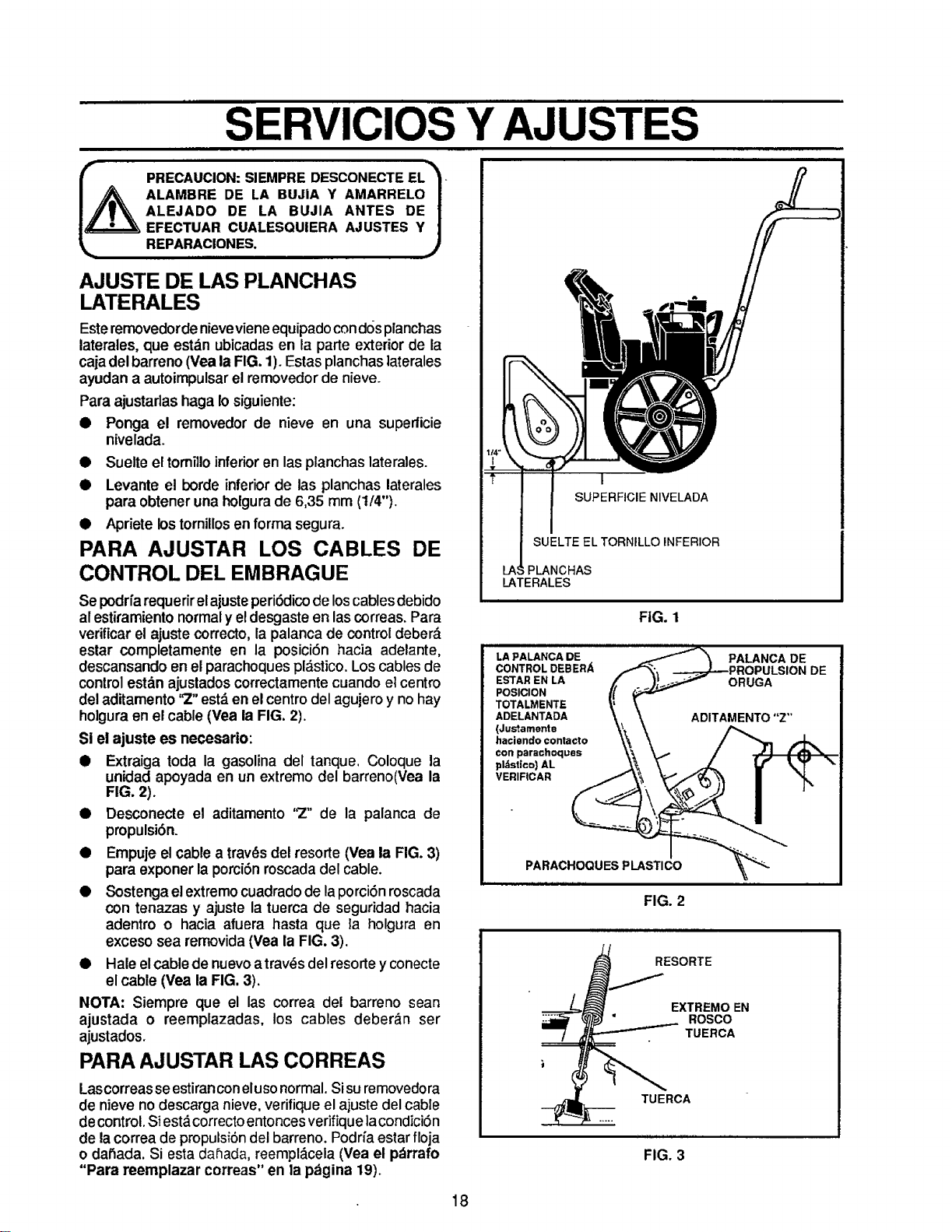
SERVICIOS Y AJUSTES
_ PRECAUCION: SIEMPRE DESCONECTE EL_'_.
ALAMBRE DE LA BUJIA Y AMARRELOI
ALEJADO DE LA BUJIA ANTES DE|
EFECTUAR CUALESQUIERA AJUSTES Y/
REPARACIONES. j
AJUSTE DE LAS PLANCHAS
LATERALES
Este removedordenievevieneequipado cond()splanchas
laterales, que estdn ubicadas en la parte exterior de la
caja del barreno (Yea la FIG. 1). Estas planchas ]aterales
ayudan a autoimpulsar el removedor de nieve.
Para ajustarlas haga Io siguiente:
i Ponga el removedor de nieve en una superficie
nivelada.
• Suelte el tomillo inferior en las planchas laterales.
• Levante el borde inferior de las planchas laterales
para obtener una holgura de 6,35 mm (1/4").
• Apriete los tornillos en forma segura.
PARA AJUSTAR LOS CABLES DE
CONTROL DEL EMBRAGUE
Se podrfa requerir el ajuste peri6dico de loscables debido
al estiramiento normal y el desgaste en las correas. Para
verificar el ajuste correcto, la palanca de control deberd
estar completamente en la posici6n hacia adelante,
descansando en el parachoques pldstico. Los cables de
control est_n ajustados correctamente cuando el centro
del aditamento '_" est,, en el centro del agujero y no hay
holgura en el cable (Yea la FIG. 2).
SI el ajuste es necesario:
• Extraiga toda la gasolina del tanque. Coloque la
unidad apoyada en un extremo del barreno(Vea la
FIG. 2).
• Desconecte el aditamento 'Z" de la palanca de
propulsi6n.
• Empuje el cable a trav_s del resorte (Vea la FIG. 3)
para exponer la porci6n roscada del cable.
• Sostenga el extremo cuadrado de la porci6n roscada
con tenazas y ajuste la tuerca de seguddad hacia
adentro o hacia afuera hasta que la holgura en
exceso sea removida (Yea la FIG. 3).
• Hale el cable de nuevo atrav_s del resorte y conecte
el cable (Vea la FIG. 3).
NOTA: Siempre que el las correa del barreno sean
ajustada o reempfazadas, los cables deber_n ser
ajustados.
PARA AJUSTAR LAS CORREAS
Lascorreas seestiran coneluso normal. Sisu rernovedora
de nieve no descarga nieve, verifique el ajuste del cable
de control. Siest_.correcto entonces verifique la condici6n
de la correa de propulsi6n del barreno. Podfia estar floja
o dat_ada. Si esta da_ada, reempl_cela (Yea el p_rrafo
"Para reemplazar correas" en la pagina 19).
I
SUPERFIClE NIVELADA
SUELTE EL TORNILLO INFERIOR
;PLANCHAS
LATERALES
FIG. 1
LA PALANCA DE
CONTROL DEBER/_,
ESTAR EN LA
POSICION
TOTALMENTE
ADELANTADA
(Justamente
haciendo contacto
€on parachoquas
pldstico) AL
VERIFICAR
PALANCA DE
PARACHOQUESPLASTICO
FIG. 2
..._ESORTE
TUERCA
_ TUERCA
FIG. 3
DE
18
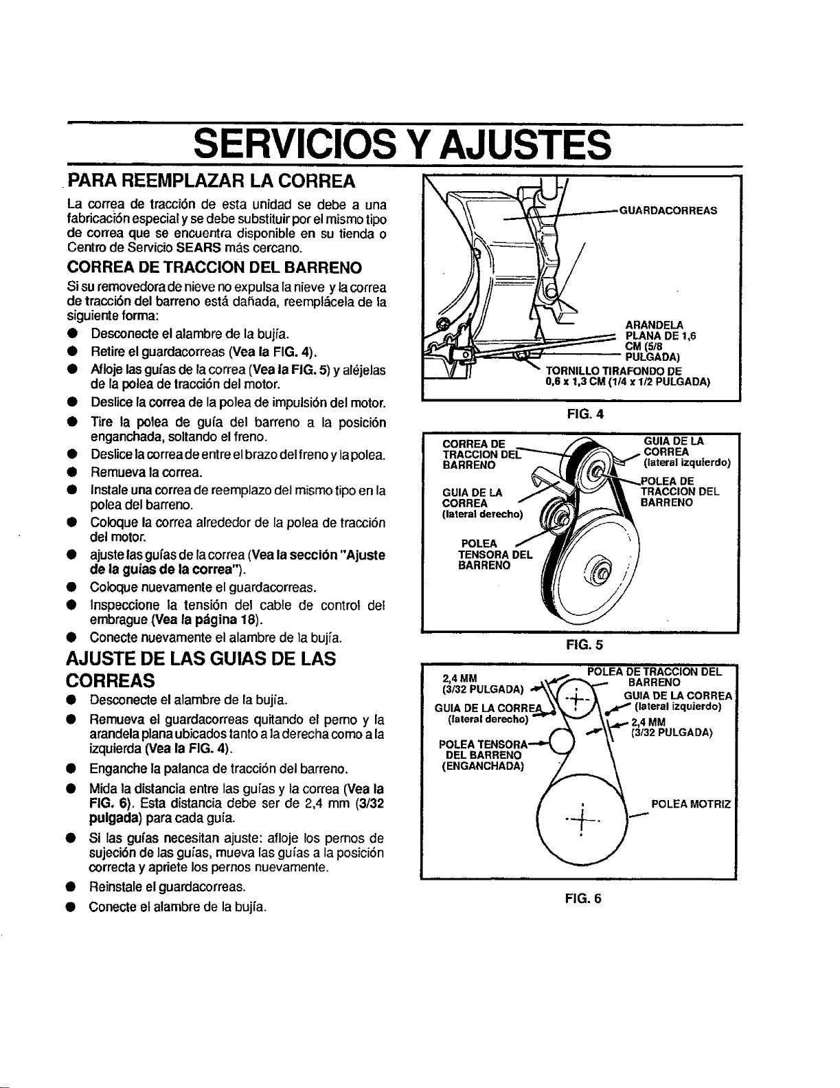
SERVICIOS Y AJUSTI S
.PARA REEMPLAZAR LA CORREA
La correa de tracciSnde esta unidad se debe a una
fabdcaci6nespecial yse debe substituir pot el mismo tipo
de correa que se encuentra disponible en su tienda o
Centro de Servicio SEARS m&s cercano.
CORREA DE TRACCION DEL BARRENO
Si su removedora de nieve no expulsa la nieve y lacorrea
de tracci6n del barreno est_ dahada, reempl&cela de la
siguiente forma:
• Desconecte el alambre de la buj_a.
• Retire el guardacorreas (Vea ia FIG. 4).
• Afloje las gufas de lacorrea (Vea ia FIG. 5) y al_jelas
de la polea de tracci6n del motor.
• Deslice la correade la polea de impulsi6n del motor.
• Tire la polea de guia del barreno a la posici6n
enganchada, soltando el freno.
• Deslice lacorreade entre el brazo del freno y lapolea.
• Remueva la correa.
• Instale unacorrea de reemplazo del mismotipo en la
polea del barreno.
• Coloque la correa alrededor de la polea de tracci6n
del motor.
• ajuste iasguras de lacorrea (Vea la seccibn "Ajuste
de ia guias de la correa").
• Coloque nuevamente el guardacorreas.
• Inspeccione la tensi6n del cable de control del
embrague (Vea la p_tgina 18).
• Conecte nuevamente el alambre de la buj[a.
AJUSTE DE LAS GUIAS DE LAS
CORREAS
• Desconecte el alambre de la bujia.
• Remueva el guardacorreas quitando el pemo y la
arandela plana ubicados tantoa laderecha como ala
izquierda (Vea la FIG. 4).
• Enganche la palanca de tracci6n del barreno.
• Mida la distancia entre las guras y la correa (Vea la
FIG. 6). Esta distancia debe ser de 2,4 mm (3/32
pulgada) para cada gufa.
• Si las gufas necesitan ajuste: afloje los pernos de
sujeciOn de lasgufas, mueva las guias a la posici6n
correcta y apriete los pernos nuevamente.
• Reinstale el guardacorreas.
• Conecte el alambre de la bujfa.
0,6 x 1,3 CM (1/4 x 1t2 PULGADA)
FIG. 4
iii i
CORREA DE GUIA DE LA
TRACCION CORREA
BARRENO (lateral izquferdo)
DE
GUIA DE LA TRACCION DEL
CORREA BARRENO
(lateral derecho)
POLEA
TENSORA DEL
BARRENO
FIG. 5
POLEA DE TRACCION DEL
2,4 MM _I"'._ _ BARRENO
(3132 PULGADA) ,,_.___ GUIA DE LA CORREA
GUIA DE LA CORRE.A_ _ jr_ f (lateral izquierdo)
(lateral derecho) -- " \v \_j.,.- 2,4 MM
_ _ ,.,,.a,'\\ (3132 PULGAI:)A)
POLEA TENSORA--_ ) V
DEL BARRENO _
(ENGANCHADA) _
,_. )....._ POLEA MOTRIZ
FIG. 6
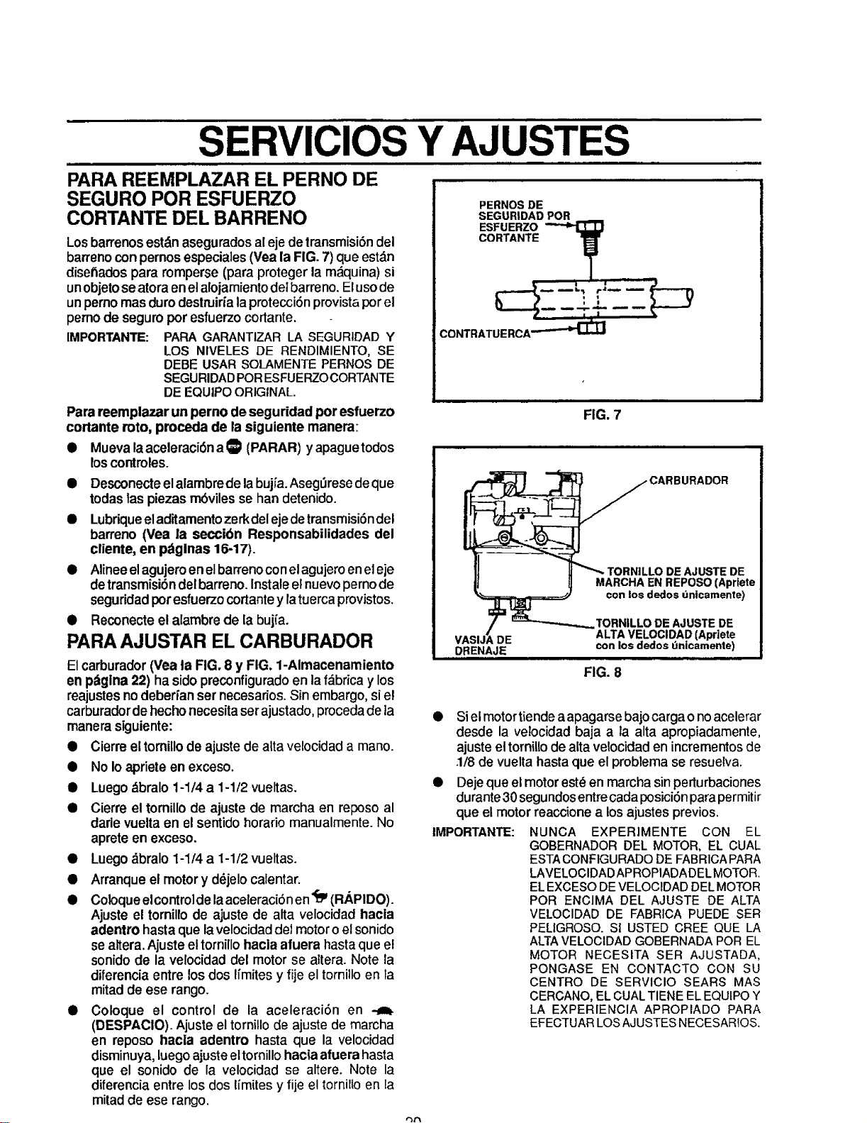
SERVICIOS Y AJUSTES
PARA REEMPLAZAR EL PERNO DE
SEGURO POR ESFUERZO
CORTANTE DEL BARRENO
Losbarrenos est_n asegurados al eje de transmisi6ndel
barreno con pernos especiales (Vea la FIG. 7) que estdn
disehados para romperse (para proteger la m_,quina) si
unobjeto se atora en el alojamiento dei barreno. El usode
un pemo mas duro destruiria la protecci6n provista por el
pemo de seguro por esfuerzo cortante.
IMPORTANTE: PARA GARANTIZARLA SEGURIDADY
LOS NIVELES DE RENDIMIENTO, SE
DEBE USAR SOLAMENTEPERNOS DE
SEGURIDADPORESFUERZOCORTANTE
DE EQUlPOORIGINAL.
PERNOS DE
SEGURIDAD POR
ESFUERZO
CORTANTE ,1__
_'!,__P
CONTRATU E RCA--'--_"_
Para reemplazar un perno de seguridad por esfuerzo
cortante roto, proceda de lasiguiente manera:
• Mueva laaceleraci6na _ (PARAR) y apaguetodos
loscontroles.
• Desconecteelalambre de labujia. Aseg_resede que
todas tas piezas rnbvilesse han detenido.
• Lubriqueeladitamentozerkdelejedetransmisi6ndel
barreno (Vea la seccibn Responsabilidades del
cliente, en pdginas 16-17).
• Alineeelagujeroenelbarrenoconelagujeroeneleje
detransmisi6ndel barreno.Instaleel nuevopernode
seguridadpotesfuerzocortantey latuerca provistos.
• Reconecteel alambrede la buj(a.
PARA AJUSTAR EL CARBURADOR
El carburador(Vea la FIG, 8 y FIG, 1-Almacenamiento
en pbgina 22) hasidopreconfiguradoen lafdbrica y los
reajustesnodebert'anser necesarios.Sin embargo,si el
carburadordehechonecesita serajustado,procedadeta
manera siguiente:
• Cierreel tomillode ajuste de altavelocidada mano.
• No Io apriete enexceso.
• Luego dbralo 1-1/4 a 1-1/2 vueltas.
• Cierre el tomillo de ajuste de marcha en reposoal
dade vuelta en elsentido horario manualmente. No
aprete en exceso.
• Luegodbralo 1-1/4 a 1-1/2 vueltas.
• Arranque el motory d_jelocalentar.
• Coloqueelcontroldelaaceleraci5nen'_ (RAPIDO).
Ajuste el tomillode ajuste de alta velocidadhacla
adentro hastaque lavelocidaddel motoroelsonido
se altera.Ajuste eltornillohacia afuera hastaque el
sonidode la velocidaddel motorse a3tera.Note la
diferencia entre losdos Ifmites y fije el torni;Io en la
mitad de ese rango.
• Coloque el control de ia aceleraciSn en
(DESPAClO). Ajuste el tornillo de ajuste de marcha
en reposo hacla adentro hasta que la velocidad
disminuya, luego ajuste eltornillo hacia afuera hasta
que el sonido de la velocidad se altere. Note la
diferenciaentre los dos limitesy fije el tornilloen la
mitad de ese tango.
FIG. 7
.CARBURADOR
TORNILLO DE AJUSTE DE
MARCHA EN REPOSO (Apriete
con los dedos untcamente)
VASIJ_ DE
DRENAJE
TORNILLO DE AJUSTE DE
ALTA VELOCIDAD (Apdete
con los dedos dnicamente)
FIG. 8
IMPORTANTE:
Si el motor tiende aapagarse bajo carga o no acelerar
desde la velocidad baja a la alta apropiadamente,
ajuste el torniUo de alta velocidad en incrementos de
.1/8 de vuelta basra que el problema se resuelva.
Deje que el motor est_ en marcha sin perturbaciones
durante 30 segundos entre cacla posici6n para permitir
que el motor reaccione a los ajustes previos.
NUNCA EXPERIMENTE CON EL
GOBERNADOR DEL MOTOR, EL CUAL
ESTA CONFIGURADO DE FABR1CAPARA
LAVELOClDADAPROPIADADEL MOTOR.
EL EXCESO DE VELOCIDAD DEL MOTOR
POR ENClMA DEL AJUSTE DE ALTA
VELOCIDAD DE FABRICA PUEDE SER
PELIGROSO. S1 USTED CREE QUE LA
ALTA VELOCIDAD GOBERNADA POR EL
MOTOR NECESITA SER AJUSTADA,
PONGASE EN CONTACTO CON SU
CENTRO DE SERVICIO SEARS MAS
CERCANO, EL CUAL TIENE EL EQUtPO Y
LA EXPERIENCIA APROPIADO PARA
EFECTUAR LOS AJUSTES NECESARIOS.
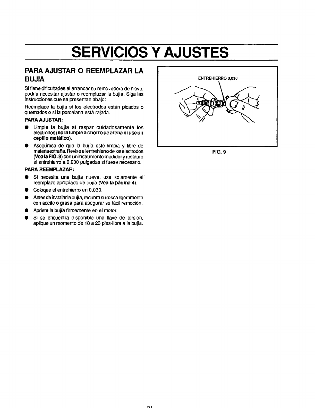
SERVICIOS Y AJUSTES
i
PARA AJUSTAR O REEMPLAZAR LA
BUJIA
Si tienedificultades al arrancar su removedora de nieve,
podria necesitar ajustar o reemplazar la bujia. Siga las
instruccionesque se presentan abajo:
Reemplace la bujia si los electrodos est_n picados o
quemados o si la porcelana est& rajada.
PARA AJUSTAR:
• Limpie la bujia al raspar cuidadosamente los
electrodos (nolaiimple a chorro de arena niuseun
cepillo met_lico).
• Asegdrese de que la bujfa est6 limpia y libre de
materiaextral_a.Reviseelentrehierrodeloselectrodos
(VealaFIG.9) conuninstrumento medidoryrestaure
elentrehierroa 0,030 pulgadas sifuese necesario.
PARA REEMPLAZAR:
• Si necesita una bujfa nueva, use solamente el
reemplazo apropiado de buj{a (Vea la pdgina 4).
• Coloque el entrehierro en 0,030.
• Antes deinstalar labujfa, recubrasurosca ligeramente
con aceite 0 grasa para asegurar su f_cil remociSn.
• Apriete la bujfa firmemente en el motor.
• Si se encuenlra disponible una Ilave de torsiSn,
aplique un momento de 18 a 23 pies-libra a fabujia.
ENTREHIERRO 0,030
FIG. 9
,'b",1
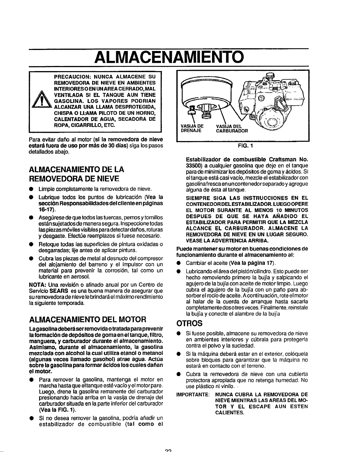
ALMACENAMIENTO
III
PRECAUCION: NUNCA ALMACENE SU
REMOVEDORA DE NIEVE EN AMBIENTES
INTERIORES 0 ENUNAREA CERRADO, MAL
VENTILADA S! EL TANQUE AUN TIENE
GASOLINA. LOS VAPORES PODRIAN
ALCANZAR UNA LLAMA DESPROTEGIDA,
CHISPA 0 LL-AMA PILOTO DE UN HORNO,
CALENTADOR DE AGUA, SECADORA DE
ROPA, C[GARRILLO, ETC.
Para evitar dat_oal motor(si la removedora de nieve
estard fuera de uso por rods de 30 dias) siga lospasos
detalladosabajo.
ALMACENAMIENTO DE LA
REMOVEDORA DE NIEVE
I Limpiecompletamentela removedorade nieve.
I Lubrique todos los puntos de lubricaci6n (Vea la
seccibn ResponsabUidades del cliente en pdginas
16-17).
• Aseg_resedequetodoslastuercas,pernosy tornillos
estdnsujetadosdemanera segura.Inspeccionetodas
laspiezasm6vilesvisiblesparadetectardafios,roturas
y desgaste. Efect_e reemplazos si fuese necesario.
• Retoque todas las superficiesde pinturaoxidadas o
desgarradas; lijeantesde aplicarpintura.
• Cubra laspiezasde metalaldesnudode]compresor
del alojamiento del barreno y el impulsorcon un
material para prevenir la corrosi6n, tal como un
lubricanteen aerosol.
NOTA: Una mvisi6n o afinado anual pot un Centro de
ServicJoSEARS es una buena manera de asegurar que
suremovedorade nievelebrindardelm_ximo rendimiento
lasiguientetemporada.
ALMACENAMIENTO DEL MOTOR
Lagasolinadeber_ serremovida otratada para prevenir
laformacl6n de depbsitos degoma enel tanque, fiitro,
manguera, y carburador durante el almacenamiento.
Asimlsmo, durante el almacenamiento, la gasolina
mezclada con alcohol la cual utiliza etanol o metanol
(algunas veces llamado gasohol) atrae agua. ActOa
sobre la gasolina para formar dcidos loscuales dafian
el motor.
FIG. 1
Estabilizador de combustible Craftsman No.
33500) a cualquier gasolinaque deje en el tanque
para deminimizarlosdep6sitosdegomay acidos.Si
eltanqueestdcasivacio,mezcle elestabilizadorcon
gasolinafrescaenuncontenedorseparadoyagregue
algunade 6sta altanque.
SIEMPRE SIGA LAS INSTRUCCIONES EN EL
CONTENEDOR DEL ESTABILIZADOR. LUEGO OPERE
EL MOTOR SURANTE AL MENOS 10 MINUTOS
DESPUES DE QUE SE HAYA AI;IADIDO EL
ESTABILIZADOR PARA PERMITIR QUE LA MEZCLA
ALCANCE EL CARBURADOR. ALMACENE LA
REMOVEDORA DE NIEVE EN UN LUGAR SEGURO.
VEASE LA ADVERTENCIA ARRIBA.
Puede mantener su motor en buenas condiciones de
funcionamiento durante el almacenamiento al:
Cambiar el aceite (Vea la p_gina 17).
Lubricandoeldrea del pist6n/cilindroEstopuedeser
hechoremoviendoprimero la bujia y salpicandoel
agujerode labuj[a conaceite de motortimpio.Luego
cubra el agujero de la bujfa con un patio para ab-
sorber el rocfode aceite. Acontinuaci6n, roteel motor
al halar de la cuerda de arranque hasta sacarla
comptetamentedosotres veces. Finafmerite,reinstale
la buj_ay conecte el alambre de la bujia
OTROS
• Si fuese posible, almacene su removedora de nieve
en ambientes interiores y cL_bralapara protegerla
contra el polvo y la suciedad.
• Si la m_,quina deber_ estar en el exterior, col6quela
sobre bloques para garantizar que ta m_quina no
estar& en contacto con ei terreno.
Cubra la removedora de nieve con una cubierta
protectora apropiada que no retenga humedad. No
use pl&stico ni vinilo..
NUNCA CUBRA LA REMOVEDORA DE
NIEVEMIENTRASLASAREASDELMO-
TOR Y EL ESCAPE AUN ESTEN
• Para remover la gasolina, mantenga el motor en
marcha hastaque eltanqueest_ vacfo yel motor pare.
Luego, drene la gasolina remanente del carburador
presionando hacia arriba en la vasija de drenaje del
carburador situada en la parte inferior de! carburador
(Vea la FIG. 1).
• Si no desea remover la gasolina, podria afiadir un
estabilizador de combustible (tal como el
IMPORTANTE:
CALIENTES.
oo
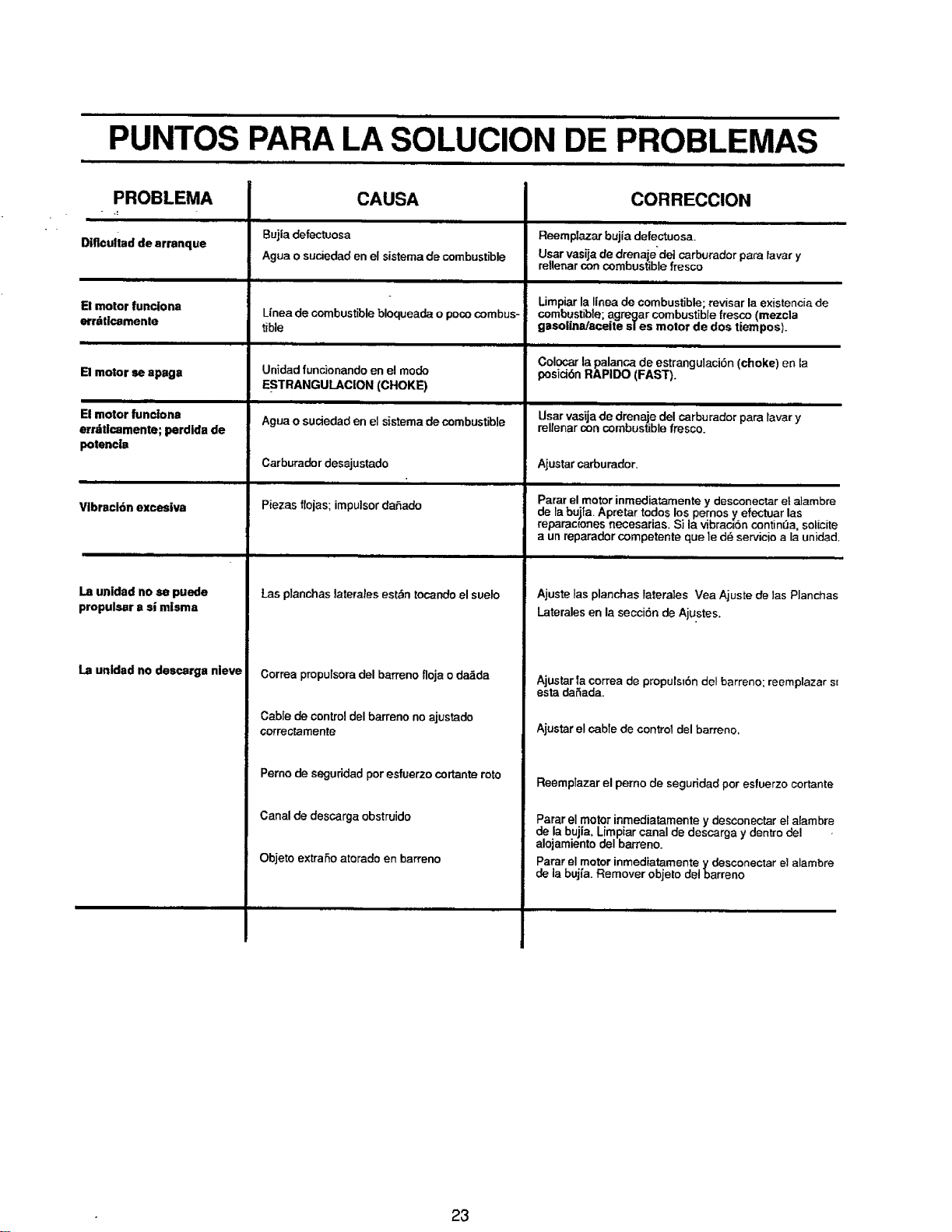
PUNTOS PARA LA SOLUCION DE PROBLEMAS
PROBLEMA
Dificultad de arranque
El motor |unciona
erriiticamenle
E! motor se apaga
Bujia defectuosa
CAUSA
CORRECCION
i l i=
El motor funciona
err,tticamente; perdida de
Agua o suciedad en el sistemade combustible
Unea de combustible bloqueade o pococombus-
tible
Unidad funcionandoen el mode
ESTRANGULACION (CHOKE)
Agua o suciedad en el sistema de combustible
Reemplazar bujia defectuosa.
Usar vasija de drenaje'del carburador para tavary
retlenarcon combustible fresco
Iimpiar la linea de combustible; revisar la existenciade
combustible; agregar combustible fresco (mezcla
gasolina/aceite sles motor de dos tiempos).
Colocar la palanca de estrangulaci6n (choke) en la
posici6n RAPIDO (FAST).
Usar vasija de drenaje del carburadorpara lavar y
rellenar con combustible fresco.
potencia
m i
Vlbracl6n excesiva
Carburador desajustado
Piezas flojas; impulsordaSado
Ajustarcarburader_
Parar el motor inmediatamente y desconectar et atambre
de labu]ia. Apretar todos los pernos y efectuar las
reparac_onesrtecesarias. Si la vibrac_'6n contin=3a,solicite
a un reparader competente que le d_ servicio a la unidad.
La unidad no se puede
propulsar a si misma
La unidad no descorga nieve
Las planchas laterales est._ntocandeel suelo
Correa propulsora del barmno floja o da_da
Cable de control del barreno no ajustado
correctamente
Pemo de seguridad por esfuerzo cortante roto
Canal de descarga obstruido
Objeto extraSoatorado en barreno
Ajuste las planchas latera]es Vea Ajuste de las Planchas
Laterales en la secci6n de Aju.stes,
Ajustar la correa de propuls_6n clel barreno; reemplazar sJ
esta de_ada.
Ajustarel cable de control del barreno.
Reemplazar el perno de seguridad por esfuerzo cortante
Parar el motor inmediatamente y desconectar el alambre
de la bujia, Limpiar canal de descarga y dentro del -
alojarnientodel barreno.
Parar el motor inmediatamente _tdesconectar el alambre
de la bujfa. Remover objeto del oarreno
23
8 ',4Vh78
MANUAL DEL
PROPIETARIO
MODELO NO.
536.884780
COMO EFECTUAR
EL PEDIDO DE''=
PIEZAS DE
REPUESTO
PARA SERVICIO DE
REPARACIONES LLAME GRATIS AL
1-800-4-REPAIR
(1-800-473-7247)
PARA OBTENERINFORMACION
SOBRELAS PARTES DE
REPUESTOY PARA ORDENAR
LLAfllE A ESTE NUMERO GRATIS:
1-'800-FON-PART
(1-800-366-7278)
SINECESITA SABER LA
UBICACION DEL CENTRO DE
SERVIClO DE REPARACIONES
SEARS EN SU AREA LLAME24
HORAS AL DIA, 7 DIAS A LA
SEMANA AL:
1-800-488-1222
CRAFTSMAN+
5 CABALLOS DE FUERZA DOS
ETAPAS, 56 CM
(22 PULGADAS)
CON PROPULSION DE
BARRENO
REMOVEDORA DE NIEVE
Arranque el6ctrico
Cada REMOVEDORA DE NIEVE tiene su propio
NUMERO DE MODELO en el marco de montaje
del motor.
Cada MOTOR tiene su propio NUMERO DE
MODELO en el ALOJAMIENTO DEL
COMPRESOR.
Siempre mencione estos NUMEROS DE MODELO
cuando solicite servicio o piezas de repuesto para
su REMOVEDORA DE NIEVE.
Todas las piezas se pueden pedir a trav_s de los
Centros de servicio de Sears, Roebuck and Com-
pany y la mayorfa de Tiendas al detalle.
AL EFECTUAR UN PEDIDO DE PIEZAS,
SIEMPRE
PROVEA LA SIGUIENTE INFORMACION:
• PRODUCTO- "REMOVEDORA DE NIEVE"
• NUMERO DE MODELO - 536.884780
• NUMERO DE MODELO DEL MOTOR -
• 143.965003
• NUMERO DE PIEZA
• DESCRIPCION DE LA PIEZA
"Su mercaderia SEARS posee valor agregado cuando
ustedconsidera que Searstieneunidadesde servicio a nivel
nacional con personae t_cnico capacitado por SEARS
...T6cnicos profesionales capacitados especfficamente en
productos SEARS, tenemos laspiezas, las herramientas y
el equipo para garantizar que cumplimos con nuestra
promesa al cliente...le proporcionamos servicio a Io que
vendemos."
SEARS, ROEBUCK AND CO., Hoffman Estates, IL 60179
Impreso en los EE.UU.