Loading ...
Loading ...
Loading ...
TEC_TM_156 | REV. D | EN 9/12/2022 Page 55 of 9615 & 24 INCH INSTALL GUIDE
CABINET SETUP
DRAFT STANDARD INSTALL & HOOK UP (CONT.)
6. Hook the chill hose’s clip to the top of the draft
standard insulation sleeve. See fig. 6.
NOTE: DO NOT REMOVE THE INSULATION
SLEEVE FROM THE DRAFT STANDARD.
7. Reinstall the draft standard top.
8. Attach the pressure regulator to the CO₂ cylinder.
See fig. 7.
NOTE: FILL THE CO₂ CYLINDER BEFORE
INSTALLATION. DO NOT LAY CO₂ CYLINDERS
ON THEIR SIDE. DO NOT DROP CO₂ CYLINDERS.
9. With the hose clamp(s), connect the provided clear
vinyl hose(s) to the pressure regulator. See fig. 7.
NOTE: MAKE SURE CLAMP IS ON THE HOSE
PRIOR TO ATTACHING.
10. Install the safety strap inside the cabinet.
See fig. 8.
11. Position the CO₂ cylinder inside the cabinet.
Then, fasten the safety strap around the cylinder.
See fig. 9.
12. Attach the tapper to the keg. See fig. 10.
13. With the hose clamp(s), connect the provided clear
vinyl hose(s) to the tapper’s air inlet.
NOTE: MAKE SURE CLAMP IS ON THE HOSE
PRIOR TO ATTACHING.
14. Pressurize the system and check the connection
points for leaks. If the system leaks, verify all
fittings and clamps are tight and seal correctly.
15. With the hose clamp(s), connect the draft standard
line(s) to the tapper.
NOTE: MAKE SURE CLAMP IS ON THE HOSE
PRIOR TO ATTACHING.
16. Engage the tapper. See fig. 11.
17. Position the keg inside the cabinet.
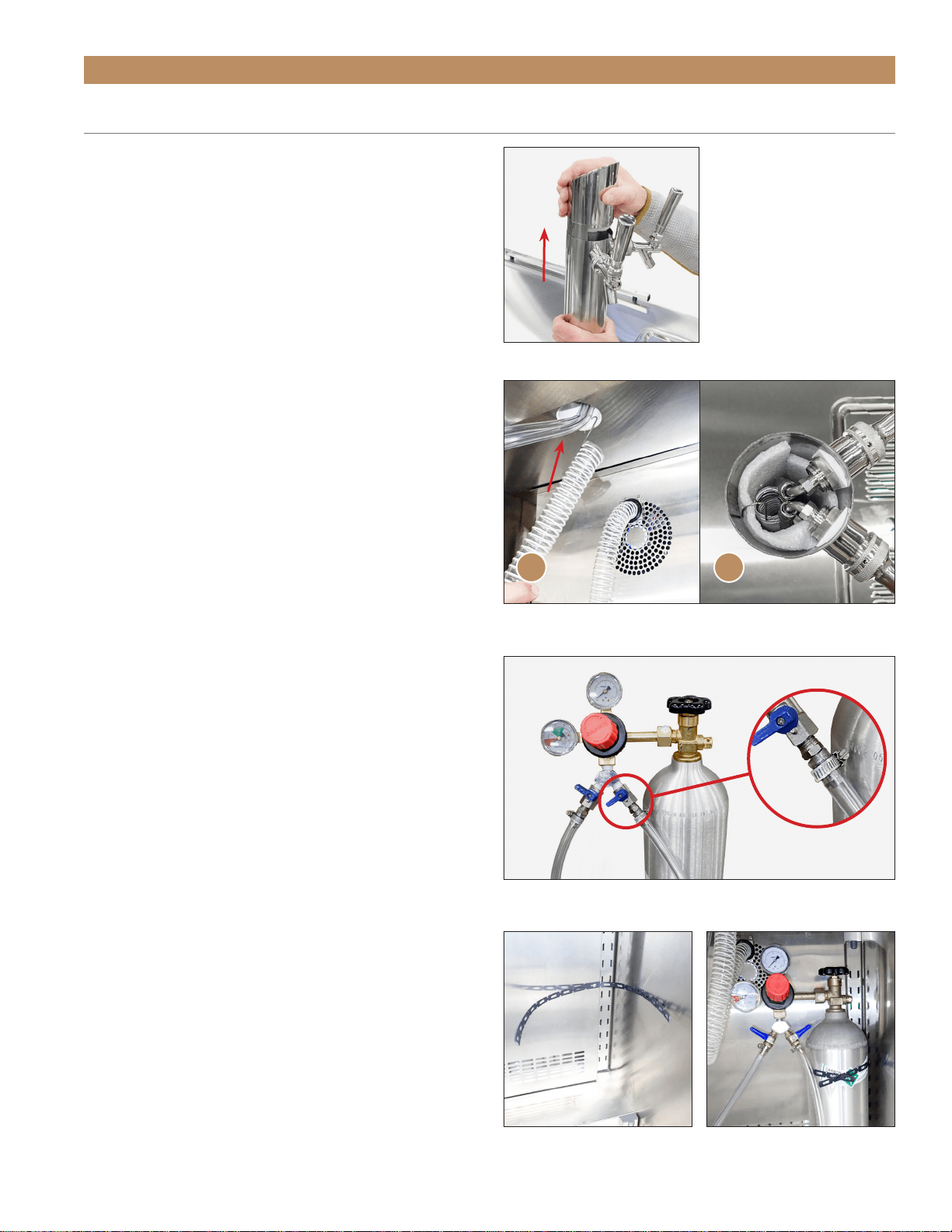
FIG. 5.
Lift the top off the draft standard.
FIG. 6.
Route the chill hose into the draft standard from below (A) and
hook it on the top of the insulation sleeve (B).
FIG. 7.
Installed pressure regulator and air hoses. Be sure the hose
clamps are tightened to prevent leaks.
FIG. 8.
Installed safety strap.
FIG. 9.
Always strap the CO
2
cylinder into the cabinet.
A B
Loading ...
Loading ...
Loading ...