Loading ...
Loading ...
Loading ...
24 25
INSTALLATIONINSTALLATION
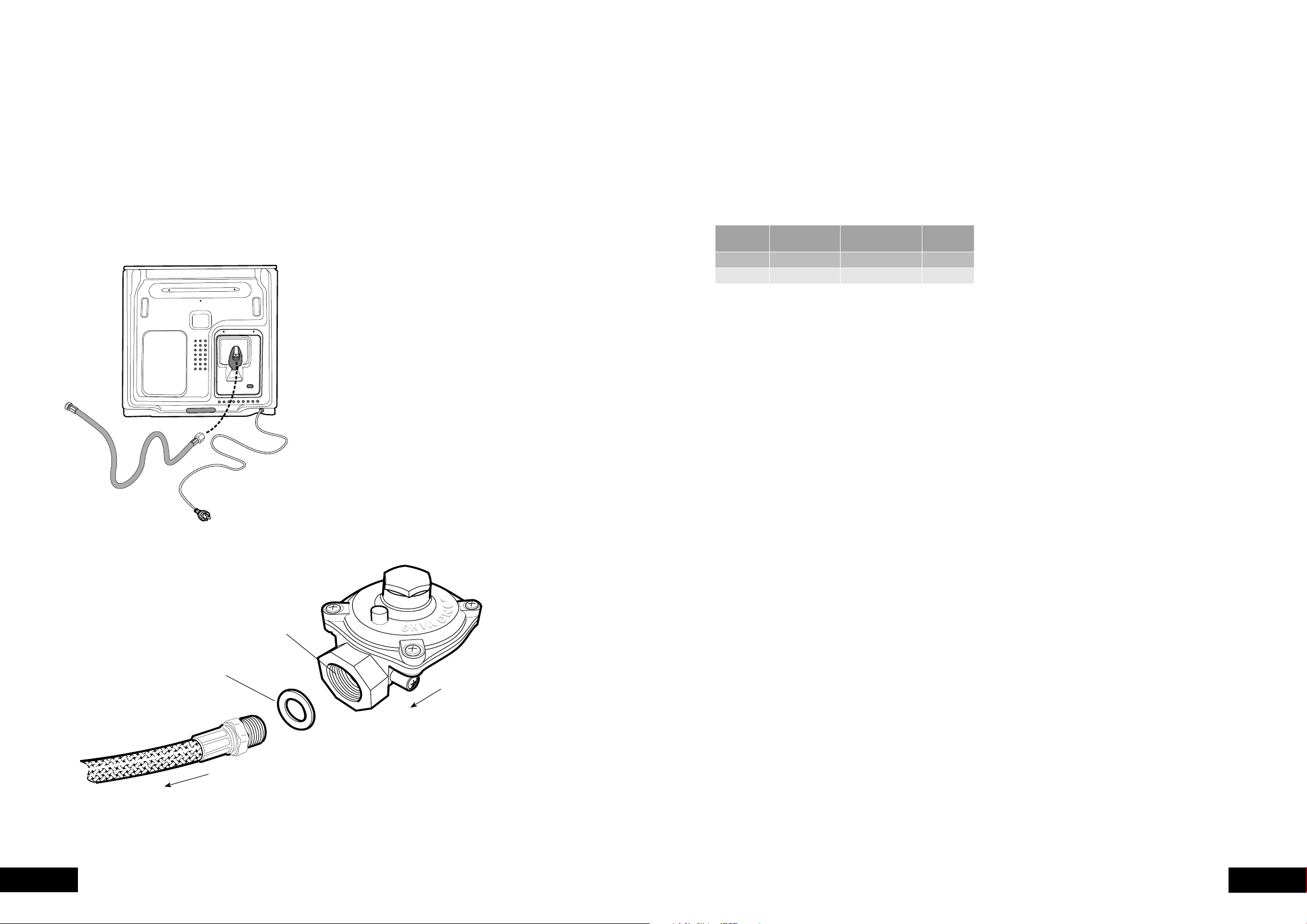
Gas Connection
of gas to which the appliance is intended to be connected
matches the gas type given on the appliance data plate.
determine gas type. A gas type label is located on the
back panel near the gas inlet.
A 1700mm long flexible hose is supplied in the pack for
installation purposes.
Connecting flexible hose
Place a spanner on the flats provided on the gas inlet
to brace the inlet against the action of wrenching when
connecting the hose to the appliance gas inlet. Failure to
do so may damage the appliance.
An approved thread sealing tape or compound is
appliance gas inlet.
Appliances for operation on N.G. & S.N.G.
For N.G. and S.N.G appliances the supplied N.G. regulator
must be fitted. For L.P.G appliances (Propane or
Universal LP) the test point fitting supplied must be fitted.
NOTE: The inlet of the regulator or test point fitting should
be fitted to the consumer piping first. The arrow on the
regulator or test point fitting indicates the direction of gas
flow. Then connect the hose to the outlet of the regulator
or test point fitting using the swivel connection on the hose
and fibre washer supplied.
Ensure the regulator or test point fitting is in
a position that is accessible with the appliance
installed and which will allow the appliance to
be withdrawn without disconnecting the hose.
GAS INSTALLATION INFORMATION
Operating Pressures
GAS TYPE
SUPPLY PRESSURE
(KPA)
NOMINAL TEST POINT
PRESSURE (KPA)
OVEN
INJECTOR
1.13 - 5.00 1.00 1.50
2.75 2.75 0.82
Testing the Operation of the Appliance
safeguard system, which includes a safety shutdown
function that operates when the presence of a flame is not
detected within a prescribed period.
system in order to facilitate purging of air from the appliance.
monitored to ensure that the ignition spark can be observed
through the round hole in the left hand side of the cover on
the bottom of the oven, and that the solenoid valve can be
heard to open and close.
1. After connecting the gas and leak testing the gas connection,
plug in the service cord and turn on the power.
3. Purging procedure:
a. Turn on the oven
b. The unit will commence sparking and the solenoid
established, the controller will shut the solenoid valve
and stop sparking, then pause for a moment before
repeating this cycle. At this point if there is still no
flame, the control system will go into safety shutdown.
c.
turn off all the controls and switch off the power
supply for a few seconds.
d. Then turn the power back on and repeat steps 2.
through to 3.d. until the gas ignites.
NOTE:
shutdown before a new ignition cycle can be attempted.
5.
6.
(this may be remote from the cooker).
the nominal outlet pressure of 1.00kPa by more than ±0.20kPa.
then check the following points.
a.
inlet pressure may be too low and adjustment of an
upstream regulator may be needed, or an upstream
regulator or valve with insufficient flow capacity may
then it may be necessary to repeat the checks whilst
measuring both the inlet and outlet pressure to determine
b.
supply line in the correct orientation, the arrow on the
base of the body indicates the direction of gas flow.
still fails to perform in a satisfactory manner it should be
replaced.
7.
is much larger or much smaller than expected, the
is unsatisfactory refer to the servicing instructions and
correct the fault if possible.
inform the customer of the problem and affix an appropriate
be dangerous, the appliance should be disconnected.
However, if only a minor fault exists, the customer may
wish to use the appliance while awaiting service.
The customer should be advised that, in the event of a fault,
or the retailer from whom the appliance was purchased.
GAS INSTALLATION INFORMATION
Gas flow
to appliance
N.G. Regulator
must be installed
Loading ...
Loading ...
Loading ...