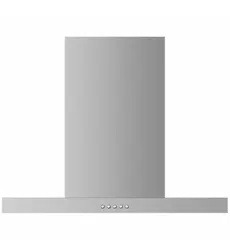
User Manual Haier HC60BLX1 Wall Rangehood
INSTALLATION INSTRUCTIONS
Optional Recirculation Accessories (when ducting externally not possible)
Recirculation Carbon filters

Product dimensions

Height of rangehood
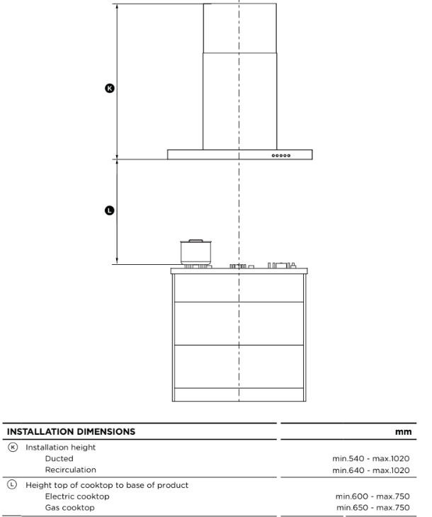
Rangehood installation height above the cooktop is the user’s preference.
Lower installation heights will improve the efficiency of capturing cooking odours, grease, and smoke. This rangehood must be installed between the minimum and maximum dimensions indicated in the table above.
Minimum installation height may be greater if required by the cooktop, refer to your cooktop installation instructions.
Venting options
Attention should be given to ensure that any applicable regulations concerning the discharge of exhaust air are fulfilled.
The rangehood can be installed to operate with the exhaust air ducted externally from the kitchen, or installed to operate with the exhaust air recirculating within the kitchen.
Ducted
For ducted installation it is recommended that 150 mm diameter, rigid or semi-rigid ducting is used. This will require a 160 mm (min) round hole in the ceiling or wall. Care should be taken to position the hole correctly.
For optimal efficiency use the shortest and straightest duct route possible and use rigid or semi-rigid ducting for reduced noise and increased airflow. Flexible metal ducting should only be used as a last resort (ie in difficult installations) and if used ensure that it is straight and smooth and extended as much as possible.
Recirculating
To enable the product to operate with the air recirculating, please purchase a recirculation diverter and carbon filters (refer to the ‘Parts and accessories’ section). The recirculation diverter is required to channel the air out the side vents at the top of the chimney and the carbon filters are required to remove odours.
Note: a ducting hole is not required in the wall or ceiling if the rangehood is installed to operate with exhaust air recirculating.
WARNING!
- This product is heavy and requires two persons for installation.
- Installation work and electrical wiring must be done by qualified person(s) .In accordance with all applicable codes and standards
- Failure to install the screws or fixing device in accordance with these instructions may result i electrical hazards
Installation
Ensure there is a power socket accessible behind the chimney.
1. Preparing for installation:
Before installing your rangehood:
- Please read the instructions carefully.
- Unpack the rangehood.
- Ensure that the voltage (V) and the frequency (Hz) indicated on the serial plate match the voltage and frequency at the installation site.
- Check that all functions are working.
- Check that the area behind the installation surface to be drilled is clear of any electrical cables or pipes, etc.
- The rangehood surfaces can be damaged during installation if grazed or knocked by tools. Please take care to protect the surfaces during installation.
- Protect the cooktop surface with cardboard, or the like, to prevent damage occurring whilst the rangehood is being installed above.
- Temporarily mark the height of the bottom of the rangehood and the centre of the cooktop on the wall according to the information given in the ‘Installation instructions - Height of rangehood’ section.
- The wall used for mounting the rangehood should have sufficient strength and a flat surface.
2. Attach chimney brackets and rangehood mounting screws to the wall
There are two methods of installation possible. One uses the supplied bracket. The other method attaches the rangehood to screws directly.
- Attach the Inside chimney bracket and the Hood mounting bracket in the locations shown in . Use ST4*40mm screws.
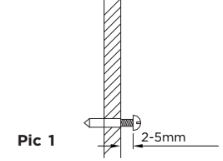
- OR Attach the Inside chimney bracket and the two mounting screws in the locations shown in pic 2 . Use ST4*40mm screws. Ensure that there is a 2-5mm gap between the screw head and the wall. See pic 1
Use the wall plugs if required.
INSTALLATION (VENT OUTSIDE)
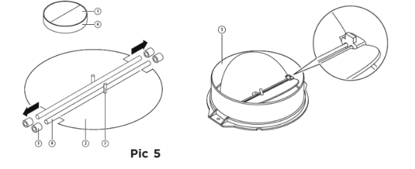
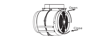
MOUNTING OF THE V-FLAP
If the cooker hood does not have an assembled V-flap 1, you should mount the half-parts to its body.The images only show an example of how to mount the V-flap, because the outlet may vary according to different models and configurations.
To mount the V-flap 1 you should:
- Mount two half-parts 2 into the body 6 the pin 3 should be top oriented;
- the axis 4 should be inserted into the holes 5 on the body;
- repeat all the operations for the 2nd half-part
INSTALLATION
1. Fix the ducting with a cable tie on the hood outlet. See 6 and 7.
2. Fix the outside chimney bracket on the outside chimney with 2pcs ST4*8mm screws. Ensure that the inside chimney can slide up and down freely. See 8.

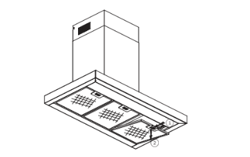
3. Put the cooker hood on the hood bracket or on the two screws. Tighten the two screws if needed. See 9.
4. Adjust the position and fix the cooker hood body with the safety screws (2pcs ST4*30mm). See 10.Note: The 6mm holes for these two screws are positioned on the back of the cooker hood. They are accessible from underneath when the grease filters are removed.

5. Extend the ducting through the hole to the external vent.
6. Plug the range hood in and turn the power on.
7. Adjust the height of the inside chimney to the position of the inside chimney bracket and fix it with screws (2pcs ST4*8mm). See 11.
Recirculation Installation only
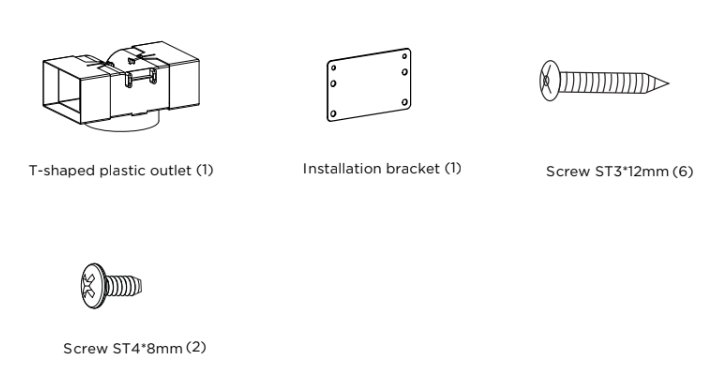
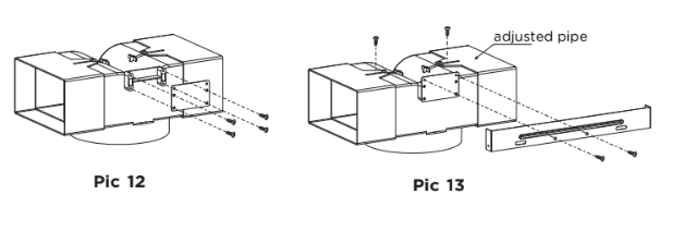
Install the recirculation T-shaped plastic outlet
- Use 4 pcs ST3*12mm screws to attach the installation bracket onto the T- shaped plastic outlet. See 12.
- Adjust the width of the T-shaped plastic outlet to the width of the inside chimney and secure it using 2p cs ST3*12mm screws. See pic 13.
- Use 2pcs ST4*8mm screws to fix the T-shaped plastic outlet to the Inside chimney bracket. See pic 13.
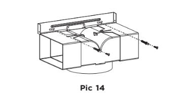
- Fix the Inside chimney bracket to the wall with 2pcs ST4*30mm screws. Use wall plugs if required. See pic 14.
- Secure the ducting to the inlet of the T-shaped plastic
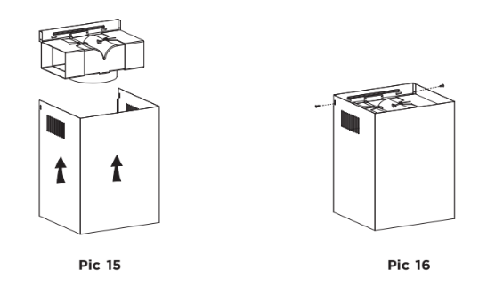
- Adjust the height of the inside chimney a nd secure it to the Inside chimney bracket wi th 2pcs ST4*8mm screws. See pic 15,16.
OPERATING INSTRUCTIONS
Start Using Your Cooker Hood
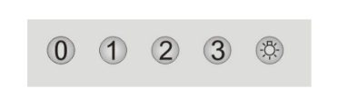
Push button
- Push the “0 ” button, and the motor will stop.
- Push the “1” button, and the motor will run at low speed.
- Push the “2” button, and the motor will run at mid speed.
- Push the “3” button, and the motor will run at high speed.
- Push the light button and the light will illuminate. Push it again and the light will turn off.
CLEANING AND MAINTENANCE
WARNING!
Unplug or disconnect the appliance from the power supply before servicing or cleaning.
IMPORTANT!
- Never use abrasive or oil based cleaners.
- Wear gloves to protect against sharp edges.
Maintenance
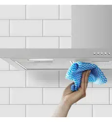
The rangehood should be cleaned regularly using a mild, liquid detergent and a clean soft cloth to avoid a build-up of grease occurring. Avoid the use of corrosive chemicals, abrasive cleaning products, hard brushes and steel wool pads. Grease deposits are corrosive which can cause damage to your rangehood.
Note: in areas of high humidity or coastal environments, cleaning should be carried out more frequently.
GREASE MESH FILTERS
As needed the aluminium grease filters should be removed and cleaned with h ot soapy water or washed separately in a dishwasher.
If washed in a dishwasher, the filter should be placed in an upright position. After rinsing and drying, replace the filters.
Note: Discolouration of the filters may occur.
INSTALLING GREASE MESH FILTERS
- To install filters for the following four steps:
- Angle the filter into the slots at the back of the hood.
- Push the button on the handle of the filter.
- Release the handle once the filter fits into a resting position.
- Repeat to install all filters.
Carbon filters – for use in recirculation mode
Active carbon filters are disposable items designed to remove grease and odours from cooking vapours before the air is channelled back into the kitchen. The active carbon filters must be replaced periodically to work properly, at least every three months, depending on the frequency with which the rangehood is used.
Note: fully saturated carbon filters can become a barrier to air movement therefore limiting rangehood performance. In the event of fire, grease laden filters could be flammable and therefore regular replacement is recommended.
CARBON FILTER-not supplied
Activated carbon filter can be used to trap odors. Normally the activated carbon filter should be changed every 3 to 6 months according to your cooking habits. The installation procedure of activated carbon filter is as below:
- Before installing or replacing the carbon filters, disconnect the mains power to the unit.
- Press the filter lock and remove the mesh filter.
- Turn the carbon filter on both sides of the motor anti - clockwise. Replace the carbon filters with the new carbon filters
- Replace the mesh filter.
- Connect the power supply to the wall socket.
MANUFACTURER’S WARRANTY
You automatically receive a 2 year Manufacturer’s Warranty with the purchase of this rangehood covering parts and labour for servicing within the country of purchase.
Fisher & Paykel undertakes to:
Repair or, at its option, replace without cost to the owner either for material or labour any part of the product, the serial number of which appears on the product, which is found to be defective within TWO YEARS of the date of purchase.
Note: this Manufacturer’s Warranty is an extra benefit and does not affect your legal rights.
This Manufacturer’s Warranty DOES NOT cover
A Service calls which are not related to any defect in the product. The cost of a service call will be charged if the problem is not found to be a product fault. For example:
- Correcting the installation of the product.
- Instructing you how to use the product.
- Replacing house fuses or correcting house wiring or plumbing.
- Correcting fault(s) caused by the user.
- Noise or vibration that is considered normal, eg drain/fan sounds, refrigeration noises or user warning beeps.
- Correcting damage caused by pests, eg rats, cockroaches, etc.
- Replacement light bulbs.
B Defects caused by factors other than:
- Normal domestic use; or
- Use in accordance with the product’s user guide.
C Defects to the product caused by accident, neglect, misuse or ‘act of God’.
D The cost of repairs carried out by non-authorised repairers or the cost of correcting such unauthorised repairs.
E Normal recommended maintenance as set out in the product’s user guide.
F Repairs when the appliance has been dismantled, repaired or serviced by other than a Fisher & Paykel Authorised Repairer or the selling dealer.
G Pick-up and delivery.
H Transportation or travelling costs involved in the repair when the product is installed outside the Fisher & Paykel Authorised Repairer’s normal service area.
Nothing in this Manufacturer’s Warranty is intended to, or does, limit any rights you may have under law to recover the costs of inspecting or returning the goods to us.
This product has been designed for use in a normal domestic (residential) environment. This product is not designed for any commercial use (whatsoever). Any commercial use by a customer will affect this product’s Manufacturer’s Warranty.
Service under this Manufacturer’s Warranty must be provided by a Fisher & Paykel Authorised Repairer (refer to the ‘Customer Care’ section at the back of this book). Such service shall be provided during normal business hours. This Manufacturer’s Warranty certificate should be shown when making any claim.
For Australian Customers
This Manufacturer’s Warranty is an extra benefit and does not affect your legal rights. Our goods come with guarantees that cannot be excluded under the Australian Consumer Law. You are entitled to a replacement or refund for a major failure and for compensation for any other reasonably foreseeable loss or damage. You are also entitled to have the goods repaired or replaced if the goods fail to be of acceptable quality and the failure does not amount to a major failure.
Please keep this user guide in a safe place.