
INSTALLATION GUIDE
NZ AU
WALL RANGEHOOD, BOX CHIMNEY
HC60BLX1 & H 90BLX1 C
GUIDE
U
S
E
R


1
CONTENTS
Safety and warnings 3
Installation instructions 5
Operating instructions
4
Cleaning and maintenance
Parts and accessories
17
Manufacturer’s Warranty
18
Customer Care
20
IMPORTANT!
SAVE THESE INSTRUCTIONS
The models shown in this user guide may
not be available in all markets and are
subject to change at any time. For current
details about model and specification
availability in your country, please go to
our website www.fisherpaykel.com or
contact your local Fisher & Paykel dealer.
Registration
Register your product with us so we can
provide you with the best service possible.
To register your product visit our website:
www.fisherpaykel.com
22
2

3
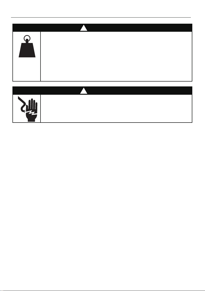
SAFETY AND WARNINGS
!
WARNING!
gk 21
(HC60)
15 kg
(HC90)
Weight Hazard
The rangehood is heavy. Please ensure adequate care is taken when
installing the rangehood to prevent personal injury. The rangehood
must be installed onto a solid wall, stud, beam or truss. Weight of the
is 12 kg and weight of is 15 kg.
!
WARNING!
Electric Shock Hazard
Always disconnect the appliance from the mains power supply before
carrying out any maintenance or repairs. Alterations to the domestic
wiring system must be made by a qualified electrician.
Failure to follow this advice may result in electric shock or death.
IMPORTANT SAFETY INSTRUCTIONS
WARNING! When using this appliance always exercise basic safety precautions
including the following:
●
Please read the entire set of instructions before installing or using this appliance.
●
Please make this information available to the person installing the appliance – doing
so could reduce your installation costs.
●
Always switch the power off prior to installation, servicing or cleaning of the rangehood.
●
This appliance must be installed and connected to the mains power supply only
by a suitably qualified person according to these installation instructions and in
compliance with any applicable local building and electricity regulations. Failure to
install the appliance correctly could invalidate any warranty or liability claims.
●
To comply with electrical safety regulations, the rangehood must be plugged into
a socket near the appliance. The socket must be accessible, or have an accessible
isolating switch, to enable the end user to isolate the rangehood from the power for
the purpose of internal cleaning or maintenance.
●
●
If the supply cord of this equipment is damaged, it must only be replaced by the
manufacturer, its service agent or similarly qualified person in order to avoid a hazard.
●
Ducting accessories are not supplied. All ducting must comply with local requirements
and building codes.
●
Attention should be given to ensure that any applicable regulations concerning the
discharge of exhaust air are fulfilled.
●
Before connecting any pipes, consult municipal ordinances to ensure that any
applicable regulations concerning the discharge of exhaust air are adhered to and
request permission from the person in charge of the building.
HC60BLX1 HC90BLX1
A power outlet should be within the range that does not affect installation and use of
the motor assembly and can either be on the wall, behind the chimney or in the ceiling.
A power outlet should be within the range that does not affect installation and use of
the motor assembly and can either be on the wall, behind the chimney or in the ceiling.

4
SAFETY AND WARNINGS
●
The minimum distance between the supporting surface for cooking vessels on the
cooktop and the lowest part of the rangehood shall be 600 mm or 650 mm if installed
over a gas cooktop.
●
Stainless steel is very easily damaged during installation if abraded or knocked by
tools. It is recommended to protect the top of the rangehood with cardboard or
polystyrene during the installation to minimise the risk of damage occurring.
●
To reduce the risk of damage occurring to the cooktop, it is recommended that
the surface of the cooktop is protected with cardboard or a similar object during
installation of the rangehood.
●
This appliance is not intended for use by persons (including children) with reduced
physical, sensory or mental capabilities, or lack of experience and knowledge, unless
they have been given supervision or instruction concerning the use of the appliance
by a person responsible for their safety.
●
Children should be supervised to ensure they do not play with the appliance. Cleaning
and user maintenance shall not be made by children without supervision.
●
You must read the details concerning the method and frequency of cleaning.
●
There is a fire risk if cleaning is not carried out in accordance with the instructions.
●
Never leave frying food unattended since grease can overheat and catch fire. The risk
of fire is even greater in the case of used oil.
●
Do not flambé under the rangehood.
●
Never use the rangehood without the filters in place.
●
During an electrostatic discharge (ESD) it is possible that the device will stop
working. By switching the device off and on the device will again work as intended.
●
CAUTION: accessible parts may become hot when used with cooking appliances.
●
Remove all packaging, including protective wrappings, before use.
Exhaus t air must not be dischar ged into an existing flue that is used for exhausting
fumes from appliances burning gas or other fuels. Range hoods and other cooking
fume extractors may adversely affect the safe operation of appliances burning gas or
other fuels (including those in other rooms) due to back flow of combustion gases. These
gases can potentially result in carbon m
onoxide poisoning. After installation of a range
hood or other cooking fume extractor, the operation of flued gas appliances should
be tested by a competent person to ensure that back flow of combustion gases does
occur.
●
no
t
5
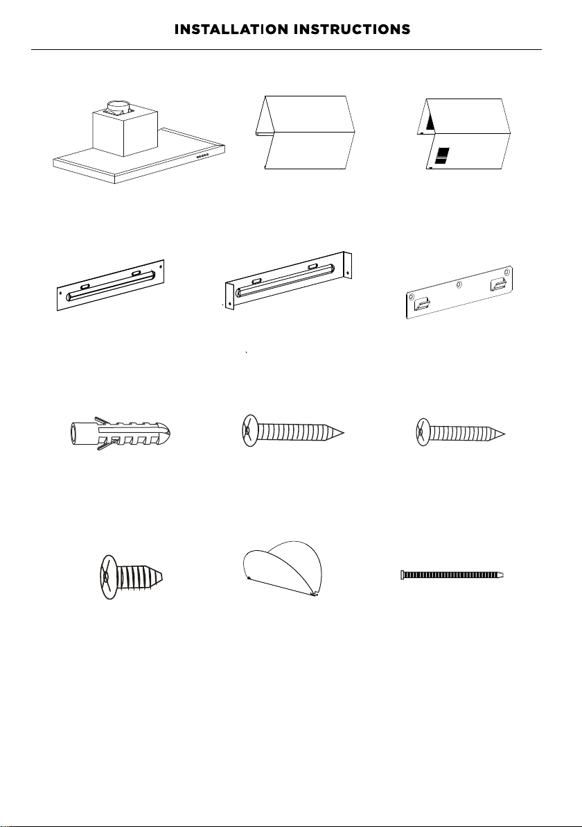
Contents of packaging
Cooker Hood (1)
Outside chimney (1)
Inside chimney (1)
Outside chimney
bracket (1)
Inside chimney
bracket (1)
Wall plug (9)
Countersunk Screw
(ST4*40mm) (7)
Pan head Screw
(ST4*30mm) (2)
Hook (1)
Hood mounting
bracket (1)
Screw (ST4× 8mm) (4)
V-flap (150) (1 pair)
Cable tie (1)
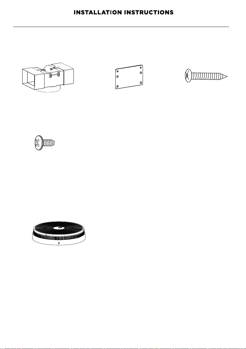
Installation bracket
Screw ST4*8mm
6
6
Carbon filter
T-shaped plastic outlet
Screw ST3*12mm
(1)
(1)
(6)
(2)
(2)
Optional Recirculation Accessories
(when ducting externally not possible)
Recirculation Carbon filters
Not Included – available separately
See arts and Accessories section for ordering details
P

Product dimensions
PRODUCT DIMENSIONS mm mm
A
Overall height of product
B
Overall width of product
C
Overall depth of product
D
Height of product
E
Width of chimney
F
Depth of chimney
G
Distance from centre of ducting outlet to back of product
H
Distance from centre of ducting outlet to side of chimney
I
Diameter of ducting outlet
J
Distance between centre of lights to back of product
IMPORTANT!
Actual product dimensions may vary by 2 mm.
Please read the entire instructions before installing the rangehood.
J
7
500
500
275
275
40 40
303
303
80 80
152 152
150 150
85 85
HC60BLX1
HC90BLX1
A
A
F
d
b
e
Ø
c
I
H
g
Power cord
±
min. 540-max. 1020 min. 540-max. 1020
5
9
8
9
8
8
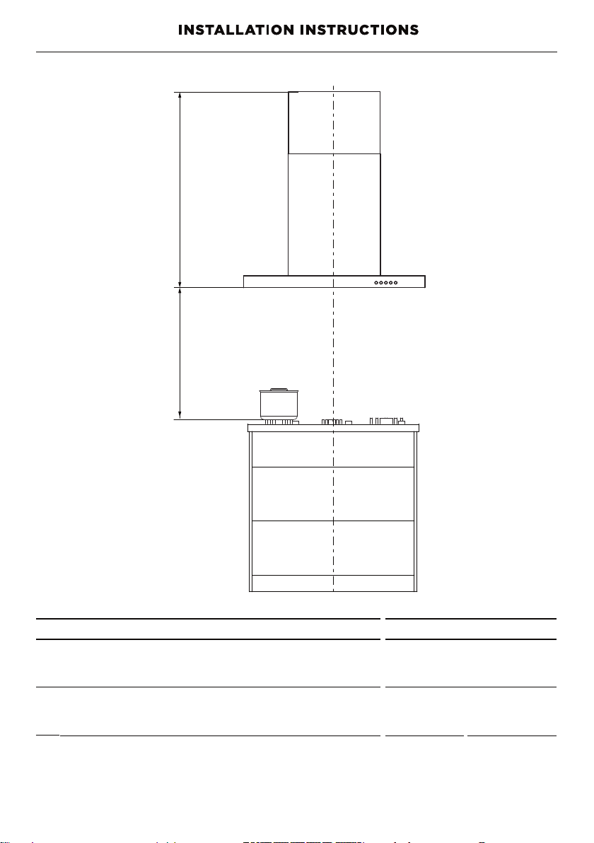
Height of rangehood
INSTALLATION DIMENSIONS mm
L
Installation height
Recirculation
min.540 - max.1020
min.640 - max.1020
min.600 - max.750
min.650 - max.750
Height top of cooktop to base of product
L
Rangehood installation height above the cooktop is the user’s preference.
Lower installation heights will improve the efficiency of capturing cooking odours,
grease, and smoke. This rangehood must be installed between the minimum and
maximum dimensions indicated in the table above.
8
Gas cooktop
Ducted
Electric cooktop
K
K
Minimum installation height may be greater if required by the cooktop, refer to your
cooktop installation instructions.
Venting options
Attention should be given to ensure that any applicable regulations concerning the
discharge of exhaust air are fulfilled.
The rangehood can be installed to operate with the exhaust air ducted externally from
the kitchen, or installed to operate with the exhaust air recirculating within the kitchen.
Ducted
For ducted installation it is recommended that 150 mm diameter, rigid or semi-rigid
ducting is used. This will require a 160 mm (min) round hole in the ceiling or wall.
Care should be taken to position the hole correctly.
For optimal efficiency use the shortest and straightest duct route possible and use rigid
or semi-rigid ducting for reduced noise and increased airflow. Flexible metal ducting
should only be used as a last resort (ie in difficult installations) and if used ensure that it
is straight and smooth and extended as much as possible.
Recirculating
To enable the product to operate with the air recirculating, please purchase a
recirculation diverter and carbon filters (refer to the ‘Parts and accessories’ section).
The recirculation diverter is required to channel the air out the side vents at the top
of the chimney and the carbon filters are required to remove odours.
Note: a ducting hole is not required in the wall or ceiling if the rangehood is installed
to operate with exhaust air recirculating.
9
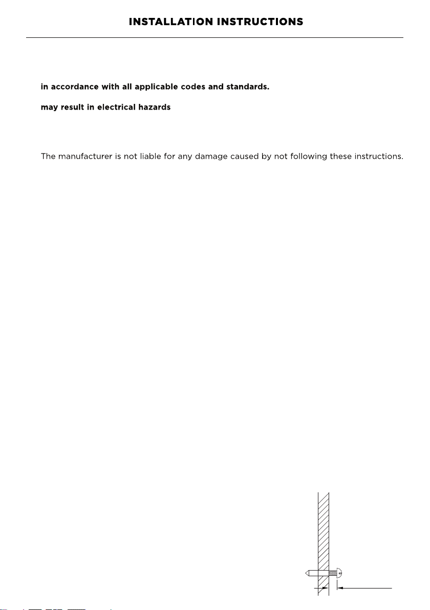
WARNING!
●
This product is heavy and requires two persons for installation.
●
Installation work and electrical wiring must be done by qualified person(s)
●
Failure to install the screws or fixing device in accordance with these instructions
IMPORTANT!
Wear gloves to protect against sharp edges.
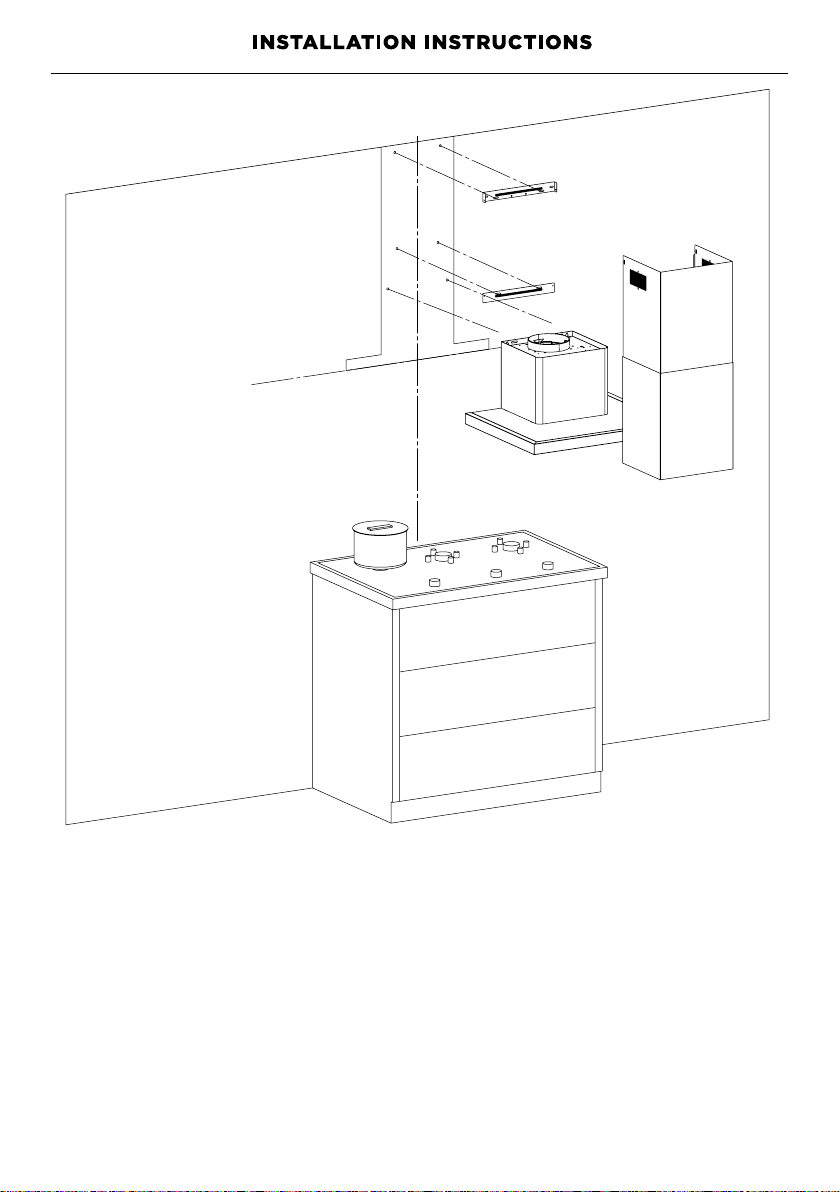
Installation
1
Preparing for installation:
Before installing your rangehood:
●
Please read the instructions carefully.
●
Unpack the rangehood.
●
Ensure that the voltage (V) and the frequency (Hz) indicated on the serial plate
match the voltage and frequency at the installation site.
●
Check that all functions are working.
●
Check that the area behind the installation surface to be drilled is clear of any
electrical cables or pipes, etc.
●
The rangehood surfaces can be damaged during installation if grazed or knocked
by tools. Please take care to protect the surfaces during installation.
●
Protect the cooktop surface with cardboard, or the like, to prevent damage occurring
whilst the rangehood is being installed above.
●
Temporarily mark the height of the bottom of the rangehood and the centre of the
cooktop on the wall according to the information given in the ‘Installation instructions
– Height of rangehood’ section.
●
The wall used for mounting the rangehood should have sufficient strength and a
flat surface.
2
Attach chimney brackets and rangehood mounting screws to the wall
There are two methods of installation possible. One uses the supplied bracket. The
other method attaches the rangehood to screws directly.
• Attach the Inside chimney bracket and the Hood mounting bracket in the
locations shown in . Use ST4*40mm screws.
• OR Attach the Inside chimney bracket and the two mounting screws in the
locations shown in
2
. Use ST4*40mm screws. Ensure that there is a 2-5mm
gap between the screw head and the wall. See
Use the wall plugs if required.
10
Ensure there is a power socket accessible behind the chimney.
2-5mm
1
3
Pic 1
pic
.
pic
pic
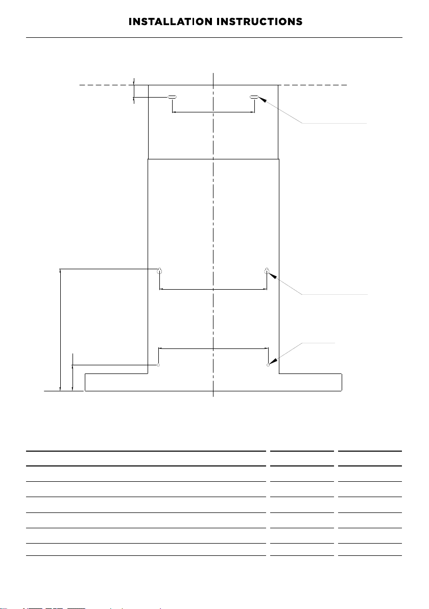
PRODUCT DIMENSIONS mm mm
N
Lower rangehood attachment point width
o
Lower rangehood attachment point height
p
Upper rangehood attachment point width
q
Upper rangehood attachment point height
r
Upper chimney bracket attachment point width
HC60BLX1
HC90BL1X1
11
Upper chimney brack
et
attachment point
Upper rangehood
attachment point
Lower rangehood
attachment point
283.5283.5
256
60
250
191 191
250
60
256
N
O
P
q
r
Upper chimney bracket attachment point height
s
s
Bracket installation
27.5 27.5
Pic 2

12
Screw Installation
hole for inside
chimney bracket
(2*wall plugs + 2*ST4*40mm screws)
hole for hook
(2*wall plugs + 2*ST4*30mm screws)
safety hole
(2*wall plugs + 2*ST4*30mm screws)
PRODUCT DIMENSIONS mm mm
Lower rangehood attachment point width
Lower rangehood attachment point height
Upper rangehood attachment point width
Upper rangehood attachment point height
Upper chimney bracket attachment point width
HC60BLX1
HC90BL1X1
283.5283.5
256
60
250
191 191
250
60
256
Upper chimney bracket attachment point height
T
U
V
W
X
Y
T
U
V
W
X
Y
27.5 27.5
Pic 3
13
Pic 4
14
ducting
v
-flap
INSTALLATION (VENT OUTSIDE)
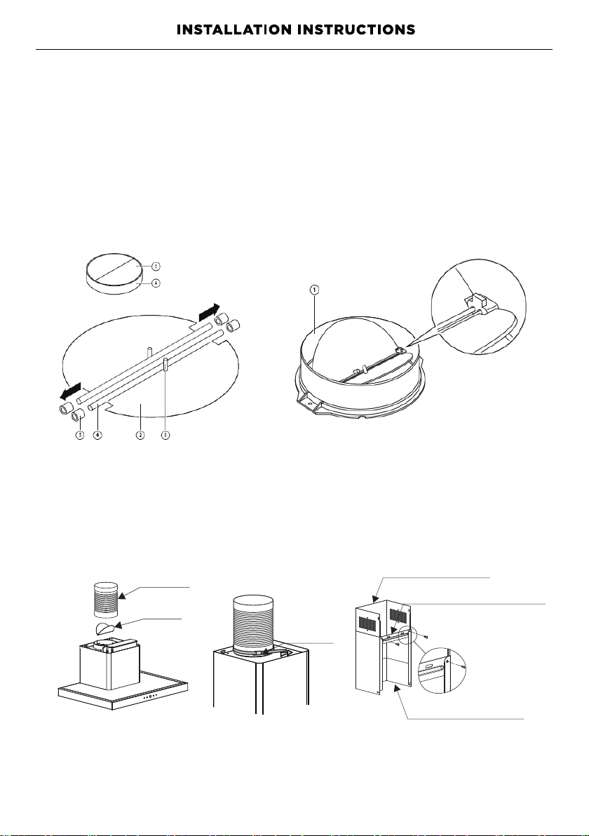
MOUNTING OF THE V-FLAP
If the cooker hood does not have an assembled V-flap 1, you should mount
the half-parts to its body.The images only show an example of how to mount
the V-flap, because the outlet may vary according to different models and
configurations.
To mount the V-flap 1 you should:
• Mount two half-parts 2 into the body 6
• the pin 3 should be top oriented;
• the axis 4 should be inserted into the holes 5 on the body;
• repeat all the operations for the 2nd half-part
INSTALLATION
1. Fix the ducting with a cable tie on the hood outlet. See 6 and 7.
2. Fix the outside chimney bracket on the outside chimney with 2pcs ST4*8mm
screws. Ensure that the inside chimney can slide up and down freely. See 8.
inside chimney
outside chimney
bracket
utside chimney
o
cable tie
Pic 5
Pic 6
Pic 7
Pic 8
pic
pic
pic
15
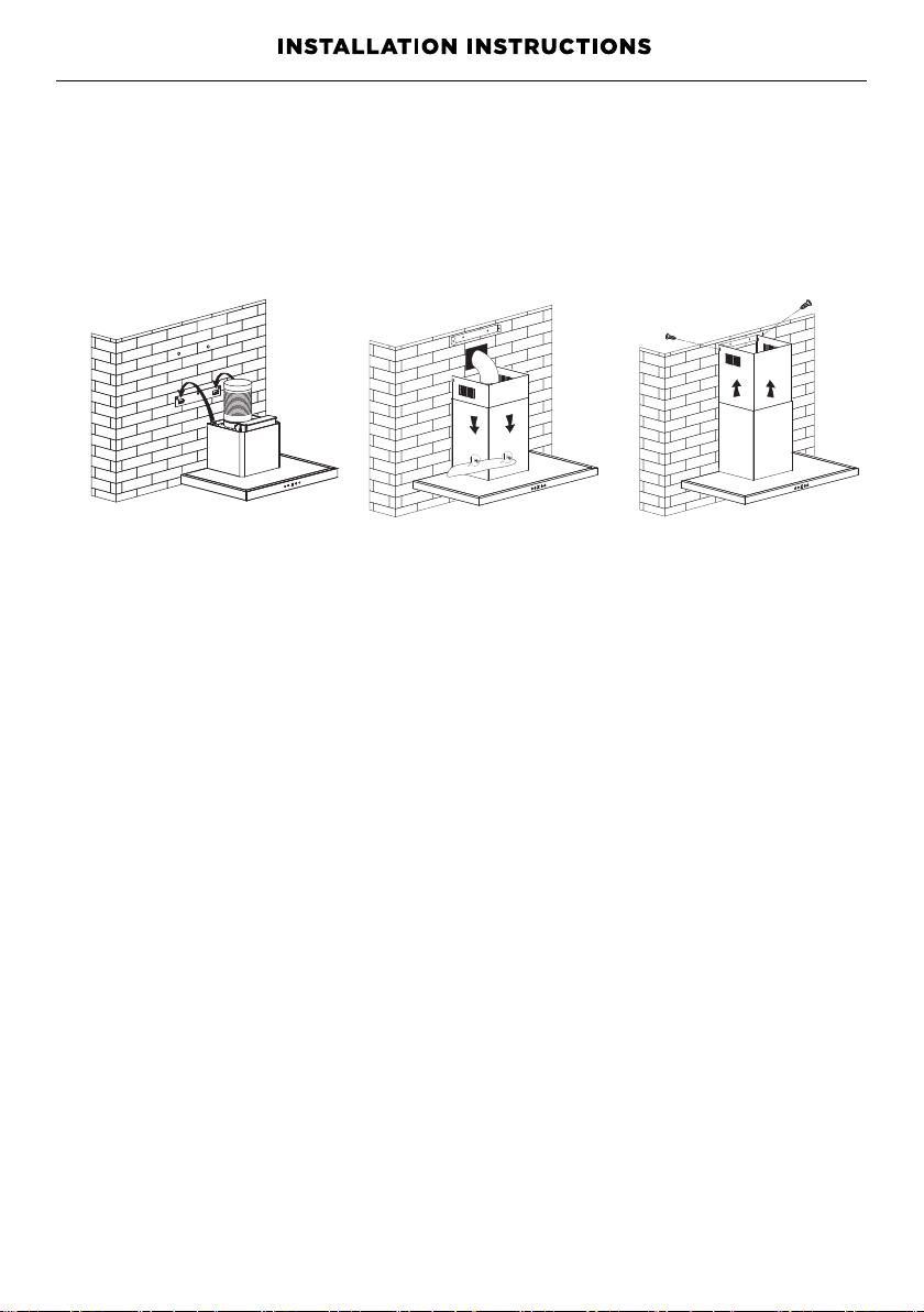
3. Put the cooker hood on the hood bracket or on the two screws.
Tighten the two screws if needed. See 9.
4. Adjust the position and fix the cooker hood body with the safety
screws (2pcs ST4*30mm). See 10.Note: The 6mm holes for these
two screws are positioned on the back of the cooker hood. They are
accessible from underneath when the grease filters are removed.
5. Extend the ducting through the hole to the external vent.
6. Plug the range hood in and turn the power on.
7. Adjust the height of the inside chimney to the position of the inside
chimney bracket and fix it with screws (2pcs ST4*8mm). See 11.
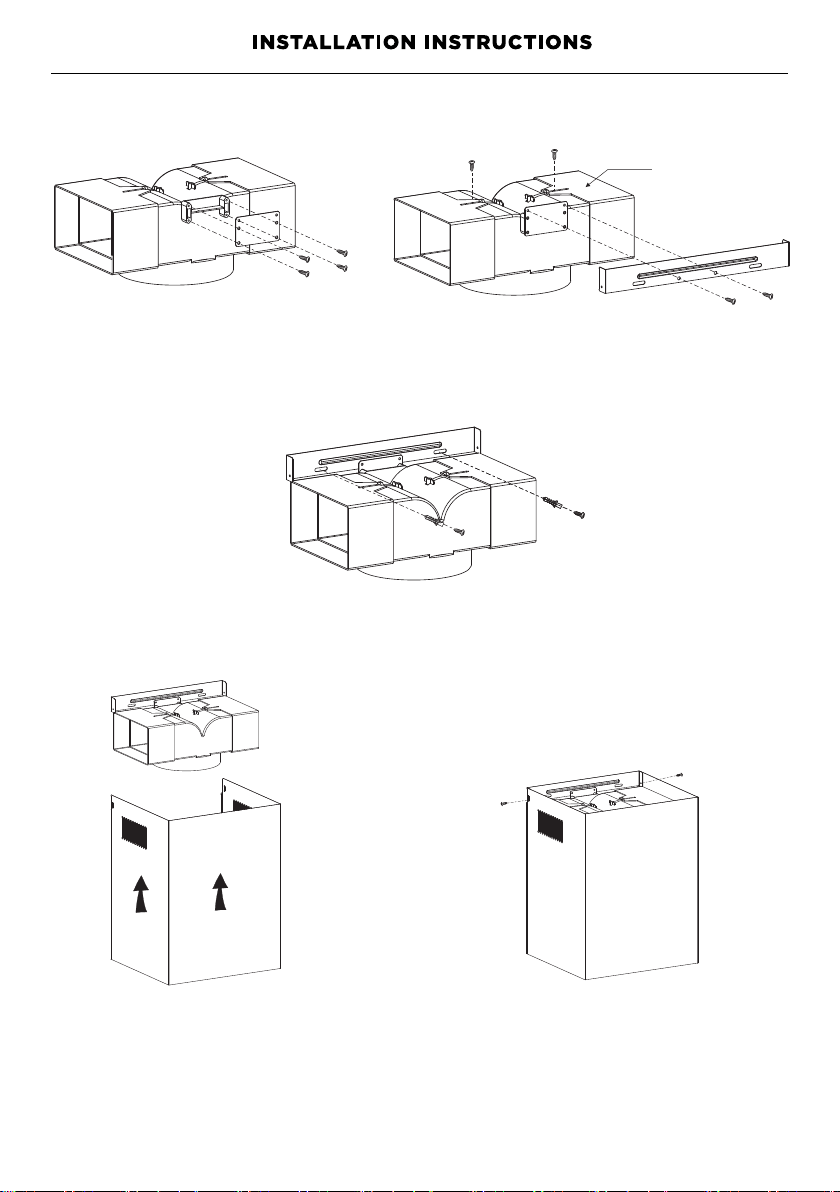
Recirculation Installation only
Install the recirculation
T-shaped plastic outlet
1. Use 4 pcs ST3*12 mm screws to attach the installation bracket onto the
T- shaped plastic outlet. See 12.
2. Adjust the width of the T-shaped plastic outlet to the width of the inside chimney
and secure it using 2p cs ST3*12mm screws. See 13.
3. Use 2pcs ST4*8mm screws to fix the T-shaped plastic outlet to the Inside chimney
bracket. See 13.
4. Fix the Insi de chimney bracket to the wall with 2pcs ST4*30mm screws. Use
wall plug s if required . See 14.
5. Secure the ducting to the inlet of the T-shaped plastic
6. Adjust the heig ht of the inside chimney a nd secure it to the Inside chimney
bracket wi th 2pcs ST4*8m m screws. See 15, 16 .
pic
pic
pic
pic
pic
pic
pic
pic
Pic 9
Pic 10
Pic 11
outlet.
(Accessory available)
adjusted pipe
Pic 12
Pic
13
Pic 14
Pic 15
Pic 16
17
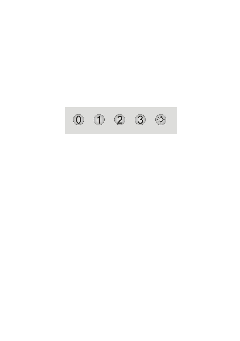
Start Using Your Cooker Hood
Push button
1) Push the “0 ” button, and the motor will stop.
2) Push the “1” button, and the motor will run at low speed.
3) Push the “2” button, and the motor will run at mid speed.
4) Push the “3” button, and the motor will run at high speed.
5) Push the light button and the light will illuminate. Push it again and the
light will turn off.
OPERATING INSTRUCTIONS
CLEANING AND MAINTENANCE
WARNING!
Unplug or disconnect the appliance from the power supply before servicing
or cleaning.
IMPORTANT!
●
Never use abrasive or oil based cleaners.
●
Wear gloves to protect against sharp edges.
Maintenance
The rangehood should be cleaned regularly using a mild, liquid detergent and a clean
soft cloth to avoid a build-up of grease occurring. Avoid the use of corrosive chemicals,
abrasive cleaning products, hard brushes and steel wool pads. Grease deposits are
corrosive which can cause damage to your rangehood.
Note: in areas of high humidity or coastal environments, cleaning should be carried out
more frequently.
18
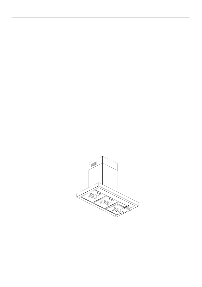
INSTALLINGGREASEMESHFILTERS
•
Toinstallfiltersforthefollowingfoursteps:
Anglethefilterintotheslotsatthebackofthehood.
Pushthebuttononthehandleofthefilter.
Releasethehandleoncethefilterfitsintoarestingposition.
Repeattoinstallallfilters.
GREASE MESH FILTERS
1.
2.
3.
4.
As needed the aluminium grease filters should be removed and cleaned with h ot
soapy water
or washed separately in a dishwasher.
If washed in a dishwasher, the filter should be placed in an upright position.
After rinsing and drying, replace the filters.
Note: Discolouration of the filters may occur.
1
2
CLEANING AND MAINTENANCE
Carbon filters – for use in recirculation mode
Active carbon filters are disposable items designed to remove grease and odours from
cooking vapours before the air is channelled back into the kitchen. The active carbon
filters must be replaced periodically to work properly, at least every three months,
depending on the frequency with which the rangehood is used.
Note: fully saturated carbon filters can become a barrier to air movement therefore
limiting rangehood performance. In the event of fire, grease laden filters could
be flammable and therefore regular replacement is recommended.
19
Open
Close
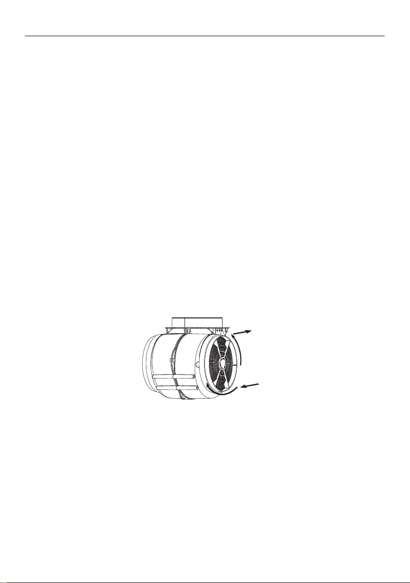
CARBON FILTER -not supplied
Activated carbon filter can be used to trap odors. Normally the activated carbon
filter should be changed every 3 to 6 months according to your cooking
habits. The installation procedure of activated carbon filter is as below:
1. Before installing or replacing the carbon filters, disconnect the mains power
to the unit.
2. Press the filter lock and remove the mesh filter.
3. shtob no nobrac eht nruT
the carbon filters with the new carbon filters.
4.
5. Connect the power supply to the wall socket.
ides of the motor anti-cl ockwise.
Replace the mesh filter.
Replace
filter
Replacing the LED light
Note: to replace the LED lights please refer to your nearest Fisher &Payket
trained and supported service technician, Customer Care, or contact us
through our website:
www.fisherpaykel.com

PARTS AND ACCESSORIES
ITEM REFERENCE NUMBER
LED lights
Aluminium filter
Recirculation carbon filter(×2)
T-shape Recirculation Outlet kit
20
H0530061789
H0530061790
H0530060509
H0530062211
+
Chimney Extension 900mm

MANUFACTURER’S WARRANTY
You automatically receive a 2 year Manufacturer’s Warranty with the purchase of this
rangehood covering parts and labour for servicing within the country of purchase.
Fisher & Paykel undertakes to:
Repair or, at its option, replace without cost to the owner either for material or labour
any part of the product, the serial number of which appears on the product, which is
found to be defective within TWO YEARS of the date of purchase.
Note: this Manufacturer’s Warranty is an extra benefit and does not affect your
legal rights.
This Manufacturer’s Warranty DOES NOT cover
A Service calls which are not related to any defect in the product. The cost of a service
call will be charged if the problem is not found to be a product fault. For example:
1 Correcting the installation of the product.
2 Instructing you how to use the product.
3 Replacing house fuses or correcting house wiring or plumbing.
4 Correcting fault(s) caused by the user.
5 Noise or vibration that is considered normal, eg drain/fan sounds, refrigeration
noises oruserwarning beeps.
6 Correcting damage caused by pests, eg rats, cockroaches, etc.
7 Replacement light bulbs.
B Defects caused by factors other than:
1 Normal domestic use; or
2 Use in accordance with the product’s user guide.
C Defects to the product caused by accident, neglect, misuse or ‘act of God’.
D The cost of repairs carried out by non-authorised repairers or the cost of correcting
such unauthorised repairs.
E Normal recommended maintenance as set out in the product’s user guide.
F Repairs when the appliance has been dismantled, repaired or serviced by other than a
Fisher&Paykel Authorised Repairer or the selling dealer.
G Pick-up and delivery.
H Transportation or travelling costs involved in the repair when the product is installed
outside the Fisher&Paykel Authorised Repairer’s normal service area.
Nothing in this Manufacturer’s Warranty is intended to, or does, limit any rights you may
have under law to recover the costs of inspecting or returning the goods to us.
This product has been designed for use in a normal domestic (residential) environment.
This product is not designed for any commercial use (whatsoever). Any commercial use
by a customer will affect this product’s Manufacturer’s Warranty.
Service under this Manufacturer’s Warranty must be provided by a Fisher & Paykel
Authorised Repairer (refer to the ‘Customer Care’ section at the back of this book).
Such service shall be provided during normal business hours. This Manufacturer’s
Warranty certificate should be shown when making any claim.
21

MANUFACTURER’S WARRANTY
For Australian Customers
This Manufacturer’s Warranty is an extra benefit and does not affect your legal rights.
Our goods come with guarantees that cannot be excluded under the Australian
Consumer Law. You are entitled to a replacement or refund for a major failure and
for compensation for any other reasonably foreseeable loss or damage. You are also
entitled to have the goods repaired or replaced if the goods fail to be of acceptable
quality and the failure does not amount to a major failure.
Please keep this user guide in a safe place.
2
2

CUSTOMER CARE
Before you call for service or assistance...
Check the things you can do yourself. Refer to the installation instructions and your user
guide and check that:
1 Your product is correctly installed.
2 You are familiar with its normal operation.
If after checking these points you still need assistance or parts, please refer to your
nearest Authorised Service Centre, Customer Care, or contact us through our website
www.fisherpaykel.com.
In New Zealand if you need assistance…*
Call your Fisher & Paykel retailer who is trained to provide information on your
appliance, or if we can be of any further help, please contact our Customer Care Centre.
Toll Free: 0800 FP CARE or 0800 372 273
Fax: (09) 273 0656
Website: www.fisherpaykel.com
Postal address: Fisher & Paykel Appliances Ltd, PO Box 58550, Botany, Auckland 2163
If you need service…*
Fisher & Paykel has a network of independent Fisher & Paykel Authorised Repairers
whose fully trained technicians can carry out any service necessary on your appliance.
Your dealer or our Customer Care Centre can recommend a Fisher & Paykel Authorised
Repairer in your area.
In Australia if you need assistance…*
Call the Fisher & Paykel Customer Care Centre and talk to one of our Customer
CareConsultants.
Toll Free: 1300 650 590
Fax: (07) 3826 9298
Website: www.fisherpaykel.com
Postal address: Fisher & Paykel Appliances Ltd, PO Box 798, Cleveland QLD 4163
If you need service…*
Fisher & Paykel has a network of Fisher & Paykel trained and supported service
technicians responsible for servicing only Fisher & Paykel branded appliances. Our
Customer Care Centre can recommend a Fisher & Paykel trained and supported service
technician in your area.
*If you call, write or contact our website please provide: your name and address, model
number, serial number, date of purchase and a complete description of the problem.
This information is needed in order to better respond to your request for assistance.
Product details can be found under the aluminium filter.
Registration
Register your product with us so we can provide you with the best service possible.
To register your product visit our website: www.fisherpaykel.com
2
3

CUSTOMER CARE
Complete and keep for safe reference:
Model
Serial No.
Purchase Date
Purchaser
Dealer
Suburb
Town
Country
4
2

104033 A 10.15
© Fisher & Paykel Appliances 2015. All rights reserved.
The product specifications in this booklet apply to the specific products
and models described at the date of issue. Under our policy of continuous
product improvement, these specifications may change at any time. You
should therefore check with your Dealer to ensure this booklet correctly
describes the product currently available.
NZ AU
5
2