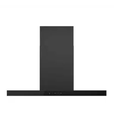

Black
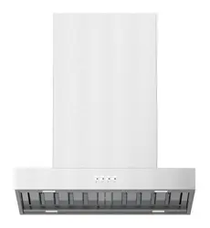
HC60BMB2 and HC90BMB2 Models
Wall Rangehood,
Box Chimney
INSTALLATION GUIDE NZ AU


3
CONTENTS
Safety and Warnings................................................................................5
Components Required ............................................................................7
Product Dimensions ................................................................................8
Clearances .............................................................................................9
Venting Requirements........................................................................... 10
Electrical Requirements......................................................................... 11
Preparing for Installation........................................................................ 12
Installation Chimney Mounting Brackets and Screws................................ 13
Bracket Attachment Points .................................................................... 14
Screw Attachment Points ...................................................................... 15
Installation Recirculation ....................................................................... 16
Carbon Filter......................................................................................... 18
Assembling V-Flap ................................................................................ 19
Installation Rangehood . . . . . . . . . . . . . . . . . . . . . . . . . . . . . . . . . . . . . . . . . . . . . . . . . . . . . . . . . . . . . . . . . . . . . . . . . . 20
Installer Checklist.................................................................................. 23

4
5
WARNING!
9 kg
(HC60)
11 kg
(HC90)
Weight Hazard
The appliance is heavy. Please ensure adequate care
is taken when installing the appliance to prevent
personal injury. The rangehood must be installed
onto a solid wall, stud, beam or truss.
Weight of the products are:
• HC60BMB2 is 9kg
• HC90BMB2 is 11kg
WARNING!
Electric Shock Hazard
Always disconnect the appliance from the mains
power supply before carrying out any maintenance
or repairs.
Installation work and electrical wiring must be
done by qualified person(s) in accordance with all
applicable codes and standards, including fire-rated
construction. Failure to do so can result in death,
electric shock, fire or injury to persons.
IMPORTANT SAFETY INFORMATION
READ THE ENTIRE SET OF INSTRUCTIONS BEFORE INSTALLING OR USING THIS APPLIANCE.
WARNING! When using this appliance always exercise basic safety precautions including the following:
z
Please read the entire set of instructions before installing or using this appliance.
z
Please make this information available to the person installing the appliance - doing so could reduce
your installation costs.
z
Always switch the power off prior to installation, servicing or cleaning of the rangehood.
z
This appliance must be installed and connected to the mains power supply only by a suitably qualified
person according to these installation instructions and in compliance with any applicable local building
and electricity regulations. Failure to install the appliance correctly could invalidate any warranty or
liability claims.
z
To comply with electrical safety regulations, the rangehood must be plugged into a socket near the
appliance. The socket must be accessible, or have an accessible isolating switch, to enable the end
user to isolate the rangehood from the power for the purpose of internal cleaning or maintenance.
z
A power outlet should be within the range that does not affect installation and use of the motor
assembly and can either be on the wall, behind the chimney or in the ceiling.
SAFETY AND WARNINGS

6
z
If the supply cord of this equipment is damaged, it must only be replaced by the manufacturer, its
service agent or similarly qualified person in order to avoid a hazard.
z
Ducting accessories are not supplied. All ducting must comply with local requirements and building
codes.
z
Attention should be given to ensure that any applicable regulations concerning the discharge of
exhaust air are fulfilled.
z
Before connecting any pipes, consult municipal ordinances to ensure that any applicable regulations
concerning the discharge of exhaust air are adhered to and request permission from the person in
charge of the building.
z
Exhaust air must not be discharged into an existing flue that is used for exhausting fumes from
appliances burning gas or other fuels. Range hoods and other cooking fume extractors may adversely
affect the safe operation of appliances burning gas or other fuels (including those in other rooms)
due to back flow of combustion gases. These gases can potentially result in carbon monoxide
poisoning. After installation of a range hood or other cooking fume extractor, the operation of flued
gas appliances should be tested by a competent person to ensure that back flow of combustion gases
does not occur.
z
The minimum distance between the supporting surface for cooking vessels on the cooktop and the
lowest part of the rangehood shall be 600 mm.
z
Painted surfaces are very easily damaged during installation if abraded or knocked by tools. It
is recommended to protect the top of the rangehood with cardboard or polystyrene during the
installation to minimise the risk of damage occurring.
z
To reduce the risk of damage occurring to the cooktop, it is recommended that the surface of the
cooktop is protected with cardboard or a similar object during installation of the rangehood.
z
This appliance is not intended for use by persons (including children) with reduced physical, sensory
or mental capabilities, or lack of experience and knowledge, unless they have been given supervision
or instruction concerning the use of the appliance by a person responsible for their safety.
z
Children should be supervised to ensure they do not play with the appliance. Cleaning and user
maintenance shall not be made by children without supervision.
z
You must read the details concerning the method and frequency of cleaning.
z
There is a fire risk if cleaning is not carried out in accordance with the instructions.
z
Never leave frying food unattended since grease can overheat and catch fire. The risk of fire is even
greater in the case of used oil.
z
Do not flambé under the rangehood.
z
Never use the rangehood without the filters in place.
z
During an electrostatic discharge (ESD) it is possible that the device will stop working. By switching
the device off and on the device will again work as intended.
z
CAUTION: accessible parts may become hot when used with cooking appliances.
z
Remove all packaging and protective wrappings, including on the grease filters, before use.
IMPORTANT!
SAVE THESE INSTRUCTIONS
The models shown in this user guide may not be available in all markets and are subject to
change at any time.
SAFETY AND WARNINGS

7
COMPONENTS REQUIRED
PARTS
Supplied and required
F 1x Rangehood
F 1x Outside chimney
F 1x Inside chimney
F 1x Outside chimney bracket
F 1x Inside chimney bracket
F 1x Hood mounting bracket
F 9x Wall plug (9)
F 7x Countersunk screw (ST4*40mm)
F 2x Pan head screw (ST4*30mm)
F 4x Screw (ST4 x 8mm)
F 1x Pair v-flap (150mm diameter)
F 2x Black aluminium filters (HC60BMB2)
3x Black aluminium filters (HC90BMB2)
Not supplied
F Ducting - 150mm diameter, rigid or semi-rigid
F Aluminium duct tape or cable ties for ducting
Optional accessories
F Chimney extension 900mm
H0530073719 (HC60BMB2)
H0530073719 (HC90BMB2)
Optional Recirculation Accessories
(when ducting externally not possible)
F 2x Recirculation carbon filters
H0530060509 (not supplied)
F T-shape recirculation outlet kit
H0530062211, includes:
z
1x T-shaped plastic outlet
z
1x Installation bracket
z
6x Screw ST3*12mm
z
2x Screw ST4*8mm
TOOLS
Not supplied
F Phillips screwdriver
F Box cutter
8
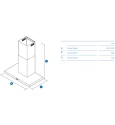
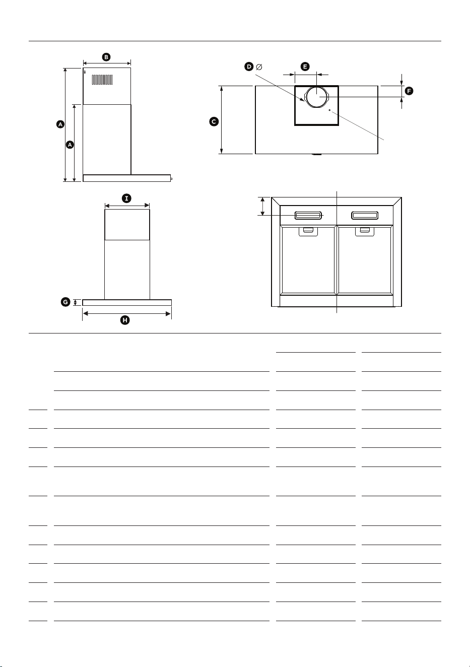
PRODUCT DIMENSIONS
HC60BMB2
HC90BMB2
mm
mm
A
Overall height of product min. 550-max. 1030
min. 550-max. 1030
Overall height of product - recirculating min. 650-max. 1030
min. 650-max. 1030
B
Depth of chimney 275
275
C
Overall depth of product 508
508
D
Diameter of ducting outlet 150
150
E
Distance from center of ducting outlet to side
of chimney
150 150
F
Distance from centre of ducting outlet to back
of product
87
87
G
Height of product 50
50
H
Overall width of product 598
895
I
Width of chimney 303
303
J
Distance between center of lights to front of product 90
90
Length of power cord 1800
1800
Actual product dimensions may vary by ± 2 mm.
Power Cord
9
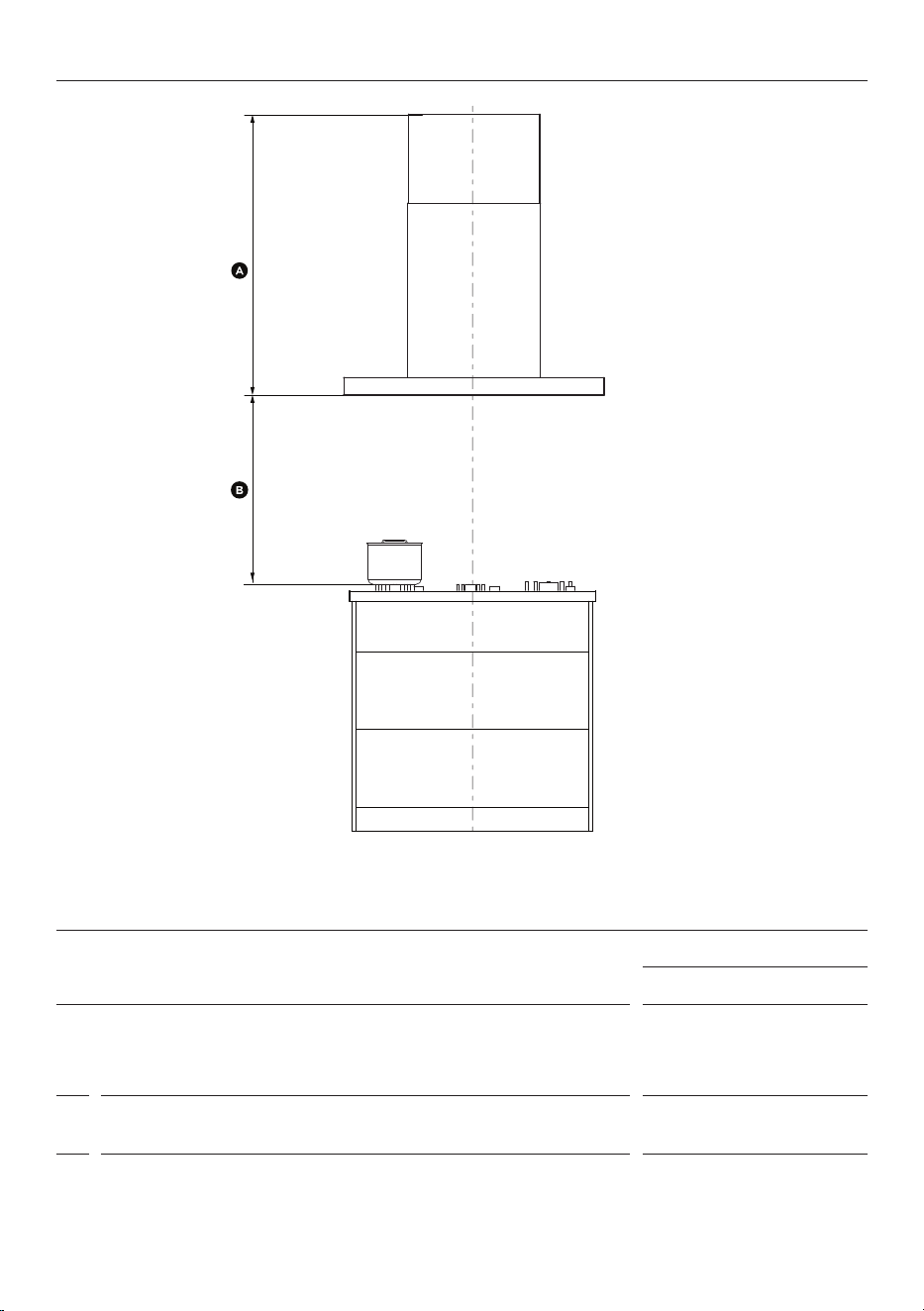
CLEARANCES
MINIMUM CLEARANCE
HC60BMB2 and HC90BMB2
mm
A
Installation height
Ducted
Recirculation
min.550 - max.1030
min.650 - max.1030
B
Height from top of cooktop to base of rangehood min.600 -
max. recommended 750
This rangehood must be installed no lower than the minimum height indicated in the table above. Minimum installation height
may be greater if required by the cooktop manufacturer or safety and warnings section on this user guide. Installation at the
minimum height will improve efficiency of capturing cooking odours, grease and smoke. Installation at the maximum height
improves ergonomics by offering increased head room.
10
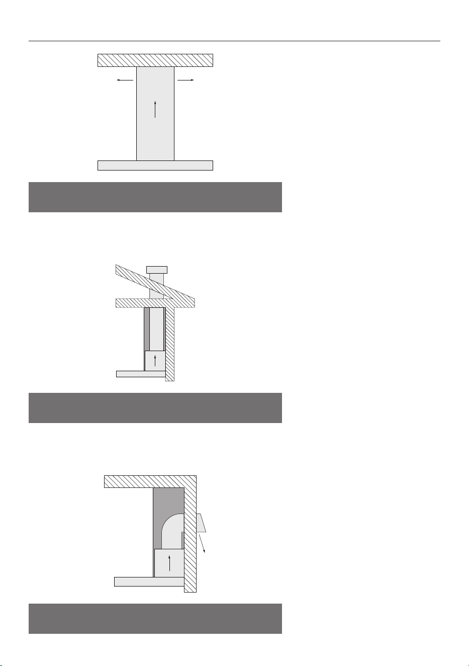
VENTING REQUIREMENTS
Recirculate with carbon filters
To enable the product to operate
with the air recirculating, please
purchase a recirculation diverter and
carbon filters.
The recirculation diverter is required
to channel the air out the side vents
at the top of the chimney and the
carbon filters are required to remove
odours.
Refer to the ‘Components Required’
section for more details.
Note: A ducting hole is not required
in the wall or ceiling
Vent through roof and vent
through exterior wall
For an externally ducted installation
it is recommended that 150mm
diameter, rigid or semi-rigid ducting
is used. Create a hole in the ceiling
that's at least 160mm in diameter,
ensuring precise positioning for
proper installation.
For optimal efficiency use the
shortest and straightest duct
route possible to reduce noise and
increase airflow.
Recirculate With Carbon Filters
Vent Through Roof
Vent Through Exterior Wall

11
ELECTRICAL REQUIREMENTS
MODEL FREQUENCY VOLTAGE
TOTAL POWER
HC60BMB2 50 Hz 220-240 V
223 W
HC90BMB2 50 Hz 220-240 V
223 W
Before connecting the rangehood to the power supply, ensure the voltage and frequency indicated on the
rating plate match that of the installation location:

12
PREPARING FOR INSTALLATION
WARNING!
z
This product is heavy and requires two persons for installation.
z
Installation work and electrical wiring must be done by qualified person(s) in accordance with all
applicable codes and standards.
z
Failure to install the screws or fixing device in accordance with these instructions may result in
electrical hazards.
IMPORTANT!
Wear gloves to protect against sharp edges.
Manufacturer is not liable for any damage caused by not following these instructions.
Before installing your rangehood:
z
Please read the instructions carefully.
z
Unpack the rangehood.
z
Ensure that the voltage (V) and frequency (Hz) indicated on the serial plate match the voltage and
frequency at the installation site.
z
Check that all functions are working.
z
Check that the area behind the installation surface to be drilled is clear of any electrical cables or
pipes, etc.
z
The rangehood surfaces can be damaged during installation.
z
Protect the cooktop surface with cardboard, or the like, to prevent damage occurring whilst the
rangehood is being installed above.
z
Temporarily mark the height of the bottom of the rangehood and the centre of the cooktop on the
wall according to the information given in the 'clearances' section.
z
The wall used for mounting the rangehood should have sufficient strength and a flat surface.
13
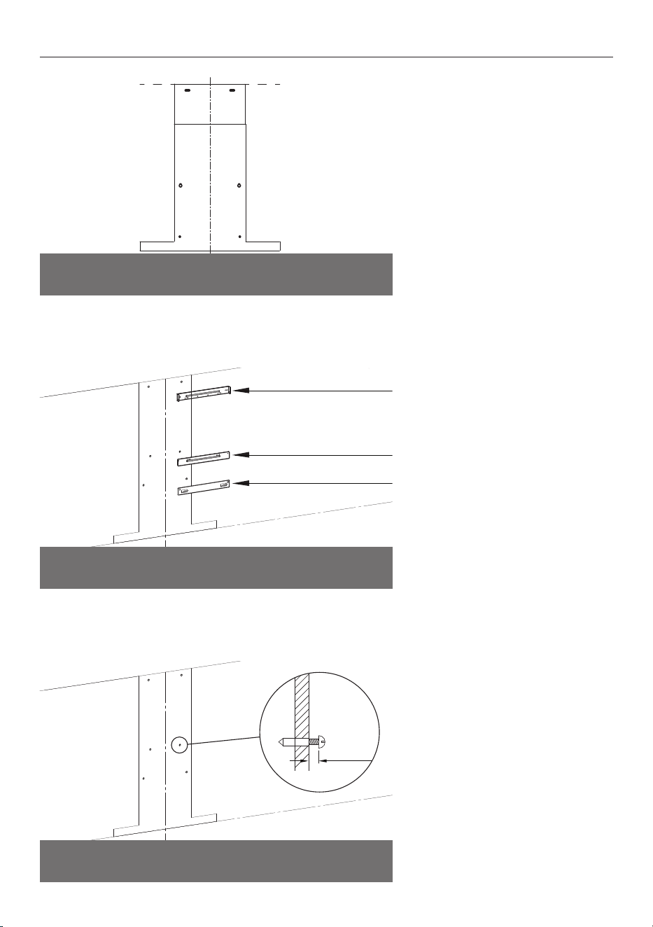
INSTALLATION CHIMNEY MOUNTING BRACKETS AND SCREWS
2-5mm
When using ST4*40mm screws,
ensure that there is 2-5mm gap
between the screw head and
the wall.
The gap is to slot the rangehood
onto the screws for hanging.
Use the wall plugs if required
There are two installation methods
available to attach rangehood to
the wall.
1. Use the supplied brackets
and screws. Refer to 'Bracket
Attachment Points' for details.
2. Use the supplied screws. Refer to
Screw Attachment Points' for details.
Same attachment location for brackets and screws
Centre and secure the brackets
using ST4*30mm and ST4*40mm
screws, 2 per bracket.
Recirculation installation:
Align recirculation adapter to the
inside chimney bracket. Refer to
'Installation Recirculation' for details.
inside chimney bracket
outside chimney bracket
hood mounting bracket
Brackets
Screws
14
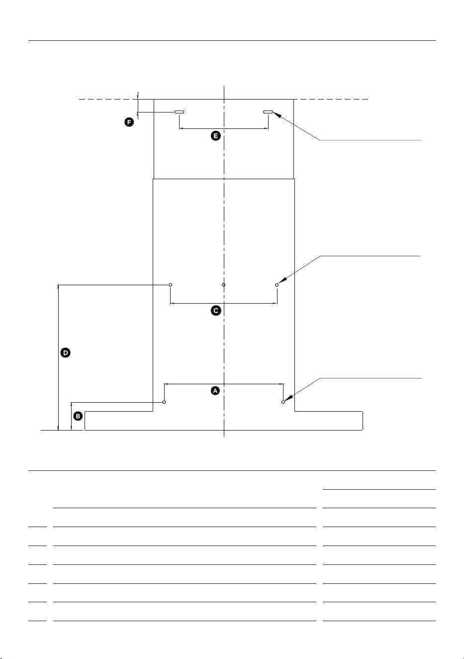
BRACKET ATTACHMENT POINTS
HC60BMB2 and HC90BMB2
mm
A
Inside chimney bracket attachment point width
256
B
Inside chimney bracket attachment point height
72
C
Hood mounting bracket attachment point width
230
D
Hood mounting bracket attachment point height
313
E
Outside chimney bracket attachment point width
191
F
Outside chimney bracket attachment point height
27.5
Inside chimney bracket
attachment point
Hood mounting bracket
attachment point
Lower rangehood
attachment point

15
SCREW ATTACHMENT POINTS
HC60BMB2 and HC90BMB2
mm
A
Safety hole attachment point width
256
B
Safety hole attachment point height
72
C
Hook hole attachment point width
250
D
Hook hole attachment point height
293.5
E
Inside chimney hole attachment point width
191
F
Inside chimney hole attachment point height
27.5
SCREWS
Hole for inside
chimney bracket
Hole for hook
Safety hole
(2*wall plugs+
2*ST4*40mm screws)
(2*wall plugs+
2*ST4*30mm screws)
(2*wall plugs+
2*ST4*30mm screws)
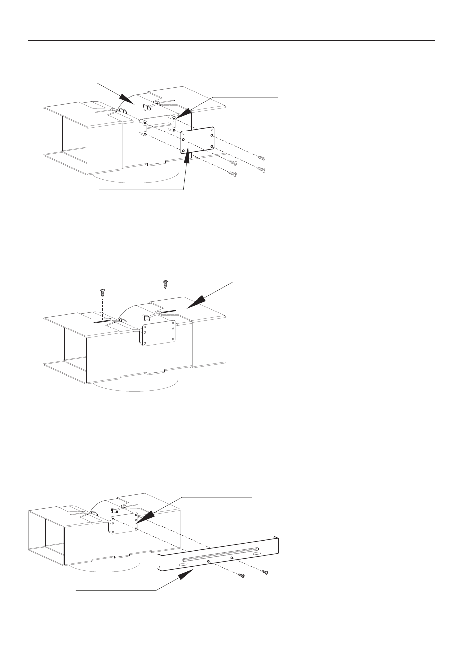
16
1. Attach the installation bracket to
the T-shaped plastic outlet using
4 pcs ST3*12mm screws.
INSTALLATION RECIRCULATION
2. Adjust the width of the outlet to
the width of the inside chimney and
secure it using 2pcs ST3*12mm
screws.
ST 3x12mm screws
adjusted pipe
T-shaped plastic outlet
3. Fix the chimney bracket to the
installation bracket using 2pcs
ST3*8mm screws.
chimney bracket
installation bracket
installation bracket
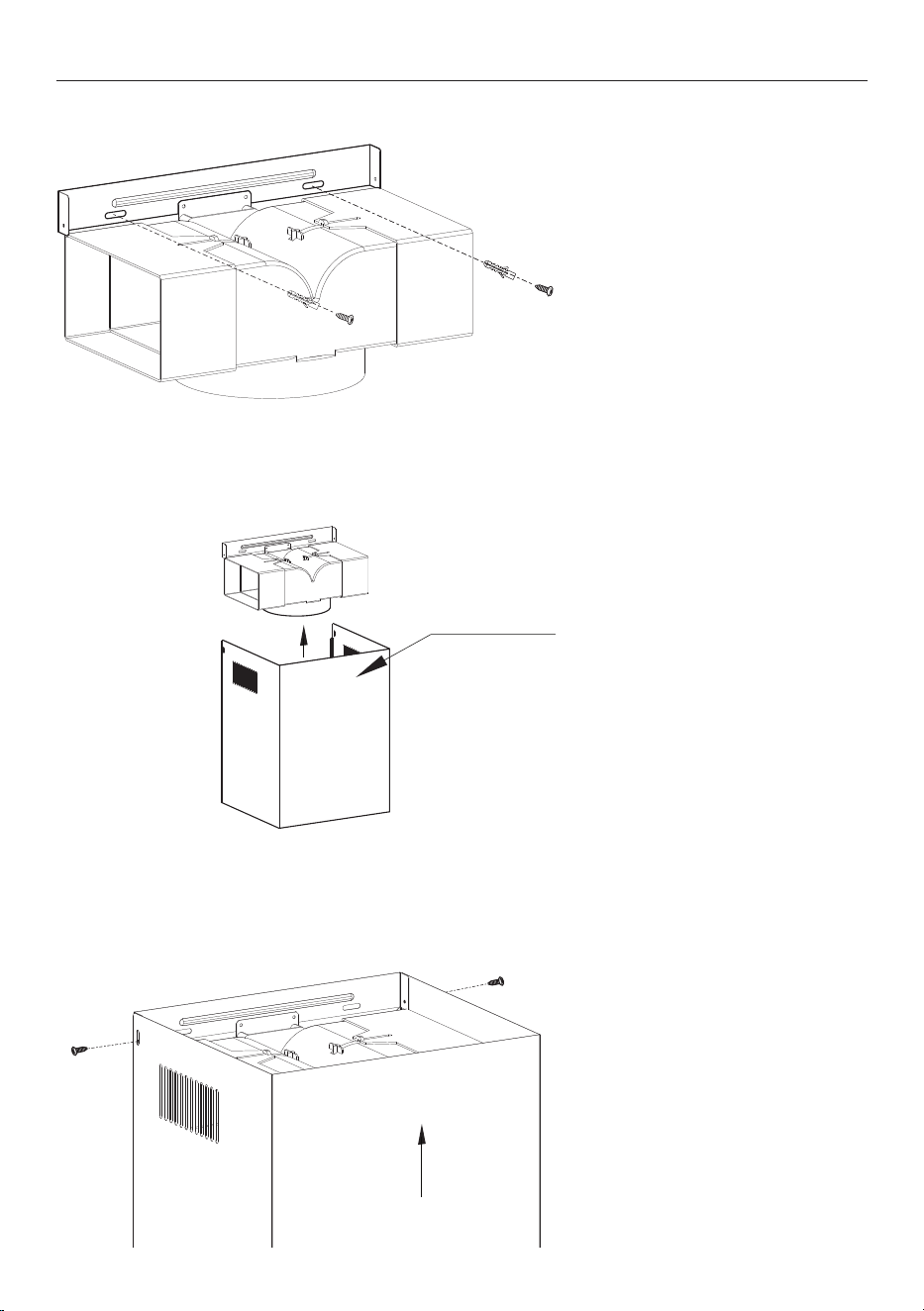
17
4. Fix the inside chimney bracket
to the wall with 2pcs ST4*30mm
screws. Use wall plugs if required.
Refer to 'Installation Chimney
Mounting Brackets and Screws' for
details on attaching chimney bracket
to the wall.
5. Secure the ducting to the inlet of
the outlet.
inside chimney
INSTALLATION RECIRCULATION
6. Adjust the height of the inside
chimney and secure it to the
inside chimney bracket with 2pcs
ST4*8mm screws.
18
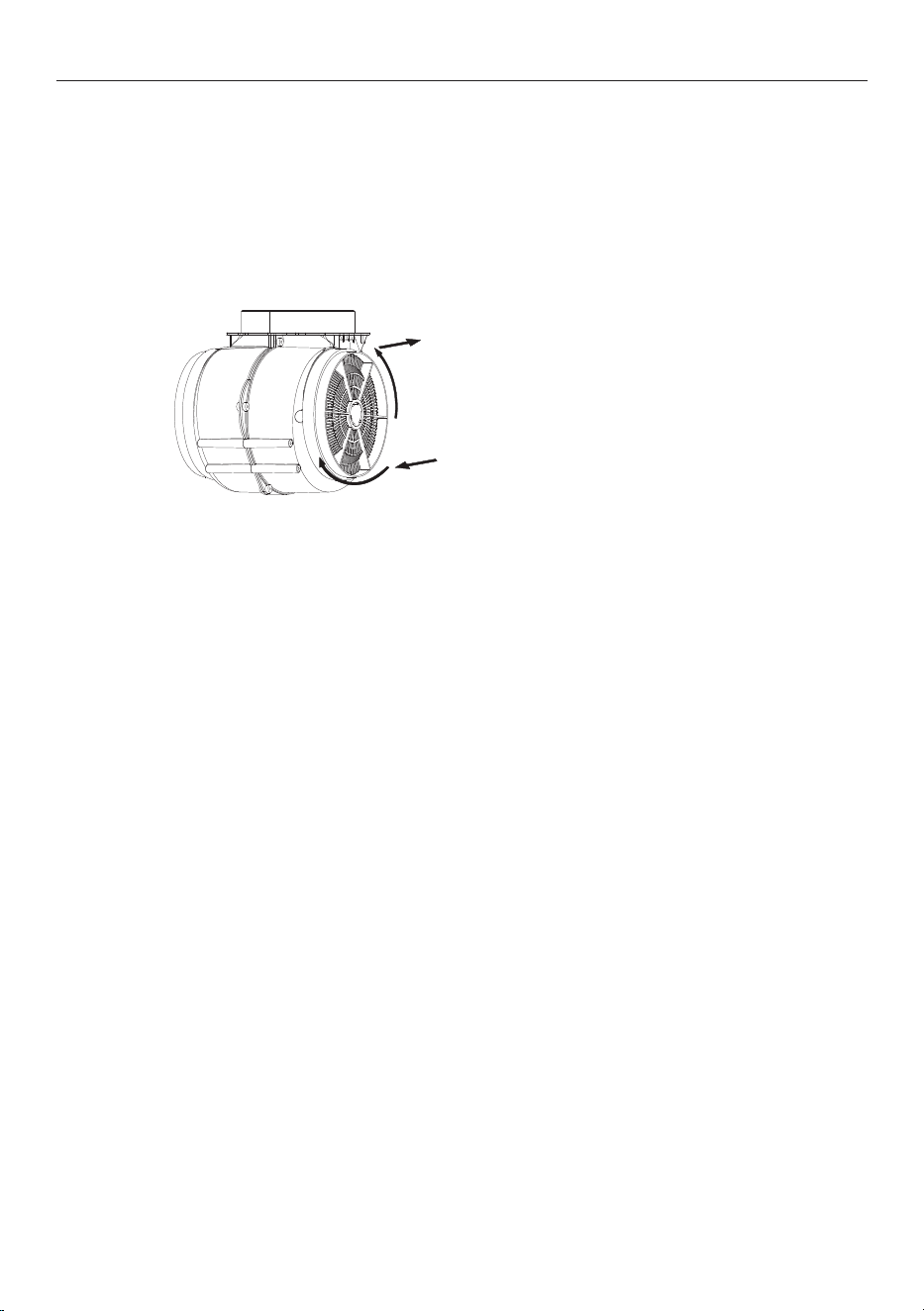
CARBON FILTER
Carbon filters are for use in recirculating mode. They are disposable and must be replaced at least every
three months to ensure the performance of the rangehood. In the event of a fire, grease-laden filters could
be flammable.
Before installing or replacing the carbon filters, disconnect the mains power to the unit.
1. Press the filter lock and remove
the mesh filter.
2. Turn the carbon filter on both
sides of the motor anti-clockwise.
Replace the existing carbon filters
with the new carbon filters.
3. Replace the mesh filter.
4. Connect the power supply to the
wall socket.
19
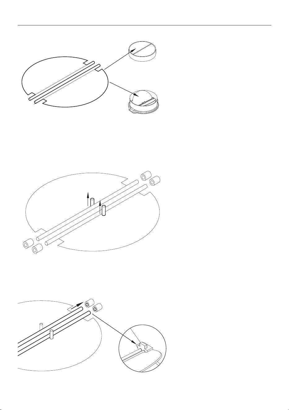
ASSEMBLING V-FLAP
1. Mount the two V-flap half-parts
into the body.
2. The pins should be facing upwards.
3. Insert the axis into the holes on
the body.
Body - outer
V-flap
Body - inside
Body - inside
20
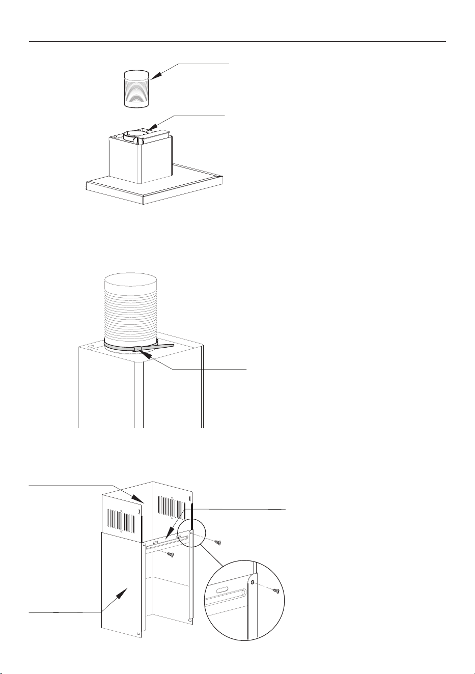
INSTALLATION RANGEHOOD
duct tape or
cable tie
ducting
assembled
v-flap in outlet
1. Place 150mm ducting around the
rangehood outlet.
2. Fix ducting to rangehood outlet
with duct tape or cable tie.
inside chimney
outside chimney bracket
outside chimney
3. Fix the outside chimney bracket
to the chimney with supplied
ST4*8mm screws.
Ensure the chimney can slide up and
down freely.
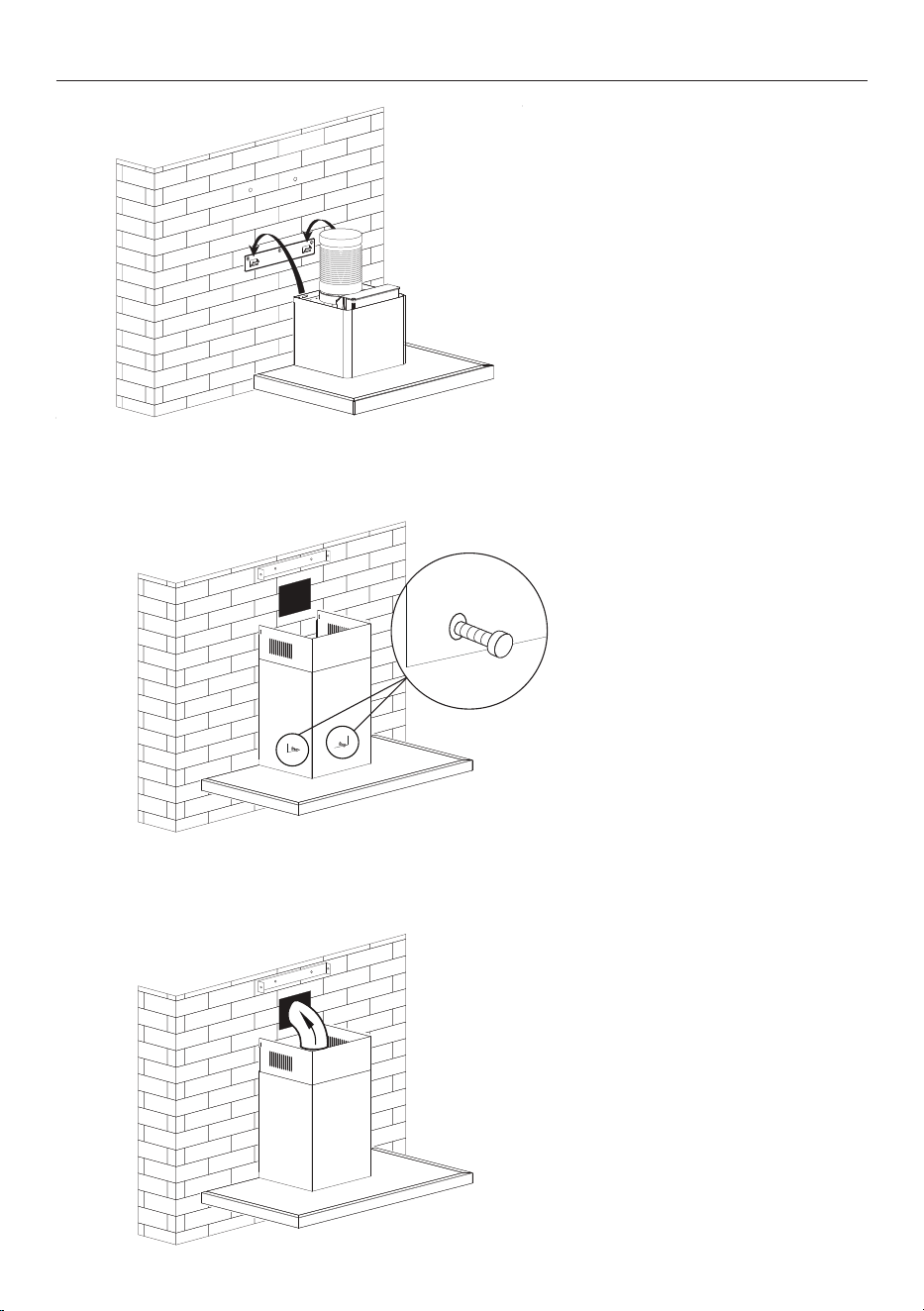
21
4. Hang the rangehood on the upper
bracket or screws (tighten the two
screws if needed).
5. Fix the rangehood chimney with
the safety screws, 2pcs ST4*30mm.
They are accessible from underneath
when the grease filters are removed.
6. Extend the ducting through the
hole to the vent.
Plug the rangehood in and turn the
power on.
INSTALLATION RANGEHOOD
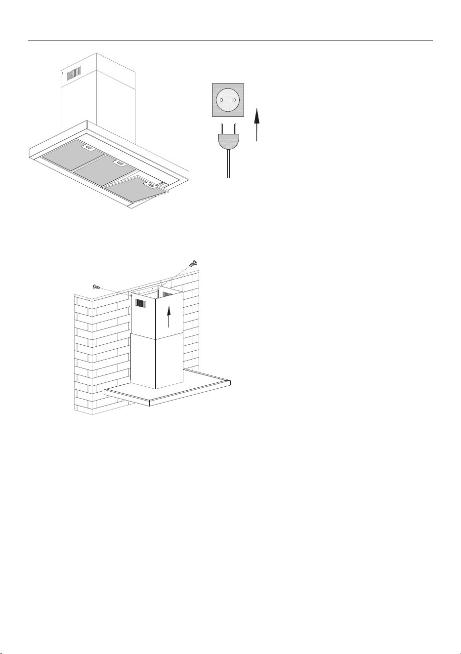
22
7. Plug in the rangehood and turn
on. Remove blue protective film
from filters.
INSTALLATION RANGEHOOD
8. Adjust the height of the inside
chimney to the position of the inside
chimney bracket and fix it with
screws 2pcs ST4*8mm.

23
Complete and keep for safe reference:
Model
Serial no.
Purchase date
Purchaser
Dealer address
Installer’s name
Installer’s signature
Installation company
Installation date
INSTALLER CHECKLIST
TO BE COMPLETED BY THE INSTALLER
F Have all packaging been removed?
F Rangehood is correctly installed
F All connections are secure
F The ducting is not bent or crushed in any areas
F Check rangehood suction
F External vent is sealed appropriately
F All local regulations have been met
F Operation has been tested (refer to rangehood user guide)
F Check for unusual noises