Loading ...
Loading ...
Loading ...
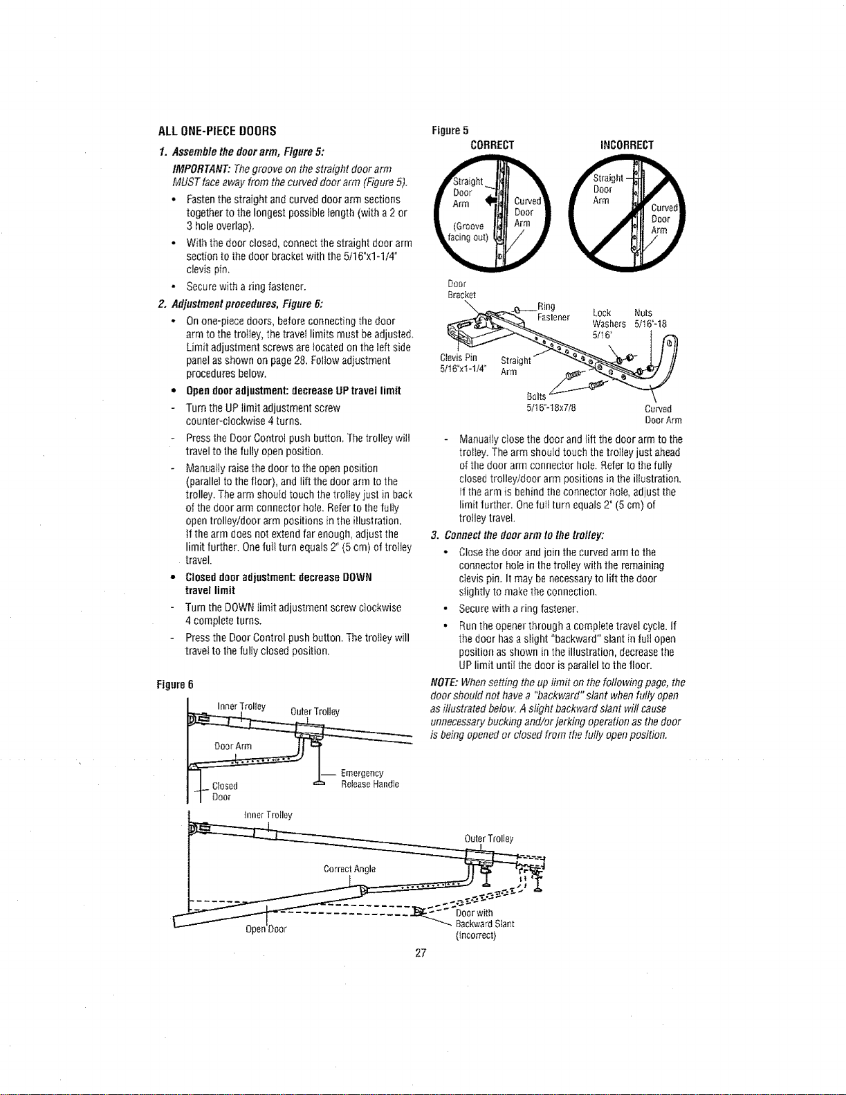
ALLONE-PIECEBOORS
1. Assemblethe door arm, Figure5:
IMPORTANT: Thegroove on thestraight door arm
MUST faceaway from thecurved door arm (Figure 5).
o Fastenthe straight and curved door arm sections
together to the longest possible length (with a2 or
3 hole overlap).
o With the door closed, connect the straight door arm
section to the door bracket with the 5116°xl-1/4"
clevis pin,
• Secure with a ring fastener.
2. Adjustmentprocedures, Figure 6:
• On one-piece doors, before connecting thedoor
arm to the trolley, the travel limits must beadjuste&
Limit adjustment screws are locatedon the left side
panel as shown on page28, Follow adjustment
procedures below.
• Opendoor adjustment: decrease UPtravel limit
Turn theUP limit adjustment screw
counter-clockwise 4 turns.
Figure5
CORRECT
Ctevis Pin Stra[g
5/16"xt-1/4" Arm
Fastener
Bolt
5/16"-t 8x7/8
INCORRECT
Lock Nuts
Washers 5/16"-18
5tt 6"
Curved
Door Arm
Press the Door Control push button. The trolley wiit
travel to thefully openposition,
Manually raisethe door to the open position
(parallet to the floor), andIitt the door arm to the
trolley. The arm shoutd touch the trolley iusl in back
of the door arm connector hole. Refer to the fully
opentrolley/door arm positions in the illustration,
it the arm does not extend far enough, adjust the
limit further. Onefull turn equals 2" (5 cm) of trolley
travel.
ClOseddoor adjustment: decrease DOWN
travel limit
Turn the DOWN limit adjustment screw clockwise
4complete turns.
Pressthe Door Control push button. Thetrolley will
travel to the fully closed position.
Figure 6
I-- Emerge.By
Manually close the door andliit the door arm to the
trolley. Thearm should touch the trolley just ahead
of the door arm connector hole. Referto the fully
closed trolley/door arm positions in the illustration.
If thearm is behind tile connector hole, adjust the
Iim[t turther. Onefurl turn equals 2" (5 cm) of
trolley travel.
3. Connectthe door arm to the trolley:
o Closethe door and join the curved arm tothe
connector hole in the trotley with the remaining
clevis pin. It may benecessaryto lift the door
slightly to make the connection.
• Secure with a ring fastener,
• Runthe openerthrough a complete travel cycle, if
the door hasa slight "backward" slant in lull open
position as shown in the illustration, decreasethe
UPlimit until the door is paraflelto the floor.
NOTE:Whensetting the up limit on thefollowing page, the
door should not havea "backward" slant whenfully open
asillustrated below. Aslight backward slant will cause
unnecessarybucking and/or jerking operation as the door
is being opened or closed from thefully openposition.
innerTroIley
OuterTrolley
Correc!Angle __
........ _-_-_-_"_'__-
-onDoor BackwardSlant
P (Incorrect)
27
Loading ...
Loading ...
Loading ...