TheChamberlain Group, inc.
845 Larch Avenue
Elmhurst, Illinois 60126-1196
www.chambedain.com
CQUS
SECURI'I
GARAGE DOOR OPENER
_)_)Model248739
For Residential Use Only
Owner'sManual
[] Please readthis manual andthe enctosedsafety materials carefully!
[] Fastenthe manual nearthe garage doorafter installation.
[] The doorWILL NOTCLOSEunlessThe ProtectorSystem®is connectedandproperlyaligned.
[] Periodicchecksofthe openerare requiredto ensuresafe operation.
[] The modelnumber label is locatedonthe leftside panel of youropener.
OFCO. NTS
Introduction 2-7
Safety Symbol and Signal Word Review.............. 2
Preparing Your GarageDoor....................... 3
Tools Needed .................................. 3
Planning .................................... 4-5
Carton inventory ................................ 6
Hardware inventory .............................. 7
Assembly 8-11
Assemble the Rai!and Install tile Trolley ............. 8
Fastenthe Rail to the Motor Unit ................... 9
Install the Idter Pulley ............................ 9
Install the Belt andAttach the Belt CapRetainer ....... 10
Set the Tension ................................ 11
Installation 11-27
Installation Safety Instructions 11
Determine the HeaderBracketLocation ............. 12
Instaitthe Header Bracket........................ 13
Attach the Rail to the HeaderBracket ............... 14
Position the Opener ............................ 15
Hangthe Opener............................... 16
Install the Door Control.......................... 17
Install the Battery Backup ........................ 18
Install the Lights ............................... I8
Attach the Emergency ReIeaseRopeand Handle ...... t8
Electrical Requirements ......................... 19
Install The Protector System_' ................. 20-23
Fastenthe Door Bracket ...................... 24-25
Connectthe DoorArm to the Trolley............. 26-27
Adjustment 28-30
Adjust the UPand DOWNTravel Limits ............. 28
Adjust the Force ............................... 29
Test the Safety ReversalSystem ................... 30
Test The Protector System® ...................... 30
Operation 31-36
OperationSafety Instructions ..................... 31
UsingYour GarageDoor Opener................... 32
Usingthe WatFMounted Door Control .............. 33
Care of Your Opener............................ 34
Having a Problem? (Troubleshooting) .............. 35
Diagnostic Chart............................... 36
Programming 37-38
To Addor Reprogram aHand-Held Remote Control.... 37
To EraseAII CodesFrom Motor Unit Memory ......... 37
3-Button Remotes.............................. 37
To Add, Reprogram or Changea Keyless Entry PIN .... 38
Repair Parts 3g-40
Rail Assembly Parts ............................ 39
Installation Parts............................... 39
Motor Unit Assembly Parts....................... 40
Accessories 41
Notes 42-43
Repair Partsand Service 44
Warranty 44
INTRODUCTION
Safety Symboland Signal WordReview
This garagedoor openerhas beendesigned and tested to offer safe service provided it is installed, operated, maintained
andtested in strict accordancewith the instructions andwarnings contained in this manual,
Mechanical
Electrical
When you see these Safety Symbols andSignal Words on
thetol!owing pages,they will alertyou to the possibility
of serious injury or deathif you do not comply with the
warnings thataccompany them, The hazard may come
from something mechanical or from electric shock, Read
thewarnings carefully.
Whenyou see this Signal Word on thefollowing pages, it
will alert you to the possibility of damage to your garage
door and/or the garage door opener if you do not compty
with the cautionary statements thataccompany it. Read
them carefu}ty,
2
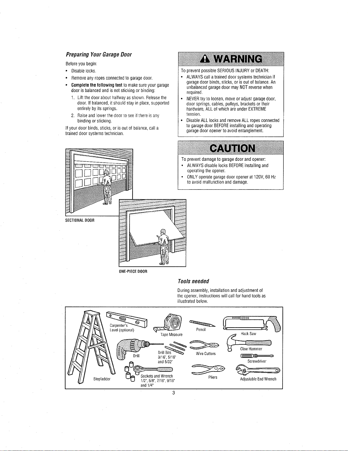
Preparing YourGarageDoor
Beforeyou begin:
- Disabtelocks.
• Remove any ropes connected to garage door.
• Completethe following test to make sureyour garage
door is balanced and is not sticking or binding:
t, Lift the door abouthalfway as shown. Releasethe
door. If balanced, it should stay in place, supported
entireIy by its springs.
2. Raiseand lower the door to see if there is any
binding or sticking.
if your door binds, sticks, or is out of balance, calf a
trained door systems technician.
To prevent possible SERIOUS iNJURYor DEATH:
, ALWAYS cait atrained door systems technician if
garage door binds, sticks, or is out of balance.An
unbalanced garagedoor may NOTreversewhen
required.
. NEVERtryto loosen, moveoradjust garage door,
door springs, cables, pulleys, brackets or their
hardware, ALL of which are under EXTREME
tension.
• Disable ALL locks and remove ALL ropes connected
to garage door BEFOREinstalling andoperating
garagedoor opener to avoid entanglement.
To prevent damage to garagedoor and opener:
• ALWAYS disable locks BEFOREinstalling and
operating the opener,
• ONLYoperategarage door opener at 120V, 60 Hz
to avoid malfunction anddamage.
SECTIONAL DOOB
ONE-PIECEDOOR
Toolsneeded
During assembly, installation and adiustment of
the opener, instructions will call for hand tools as
iitustrated below.
Stepladder
Level(optional)
TapeMeasore
Drilt
DrilI 3/t 6°, 5tl 6"
i_l and 5t32"
U 112",5/8_,7/16", 9/16°
and I/4"
Pencil
WireCutters
Pliers
/,_ HackSaw
Screwdriver
Adjustable EndWrench
Planning
identify the type and height of your garagedoor. Survey
your garageareato seeif any of theconditions below
appty to your installation. Additional materials may be
required. You may find it helpfWto refer backto this page
and the accompanying illustrations as you proceedwith
the installation of your opener_
Dependingon your requirements, there are several
installation stepswhich may calI for materials or hardware
not included in the carton.
, Installation Step 1 - Look at the wait or ceiling above
the garagedoor. The headerbracket must be securely
fastened to structural supports.
• Installation Step 5- Do you havea finished ceiting in
your garage? If so, a support bracket and additional
fastening hardware may berequired,
• installation Step 10- Depending upon garage
construction, extension brackets or wood blocks may
be neededto instaif sensors.
- Installation Step I0 - Alternate floor mounting of
the safetyreversing sensor will require hardware not
provided.
Doyou havean accessdoor in addition to the garage
door? 1tnot, Modei 7702CB EmergencyKey Releaseis
required. SeeAccessories page.
Look atthe garage door where it meets the floor. Any
gap betweenthe floor and the bottom of the door must
not exceed 1/4"(6 ram). Otherwise, the safety reversal
system may not work properly. SeeAdjustment Step 3.
Floor or door should berepaired.
SECTIONALDOORINSTALLATIONS
- Do you haveasteel, aluminum, fibergIass or glass
panel door? if so, horizontal and vertical reinforcement
is required(installation Step 11).
• Theopener should beinstalled above thecenter of the
door. if there is a torsion spring or center bearing pinto
in the way of the headerbracket, it may be installed
within 4 feet(1.2 m) to the left or right of the door
center. See Installation StepsI and tl.
• If your door is more than 7 feet (2.t m) high, see rail
extension kits listed on Accessoriespage.
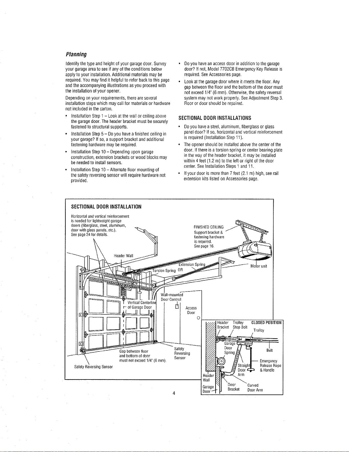
SECTIONALDOORINSTALLATION
Horizontal andvertical reinforcement
is neededfor lightweight garage
doors (fiberglass,steel, aluminum,
door withglass panels, etc,),
See page 24 for details.
Header Wail
OR
FINISHEDCEILING
Suppod bracket &
fastening hardware
is required.
See page t6.
pring
WalFmounled
DoorControl
VerticWCenterlin_
Safety Reversing Sensor
Safety
Gap between floor Reversing
and bottomof door Sensor
musl nol exceed 1/4" (6 ram).
Lrage
)or
Header Trolley CLOSEDPOSITION
Bracket StopBolt
Spriag/_( ] _e,t
_l Uoor Curved
' U Bracket DoorArm
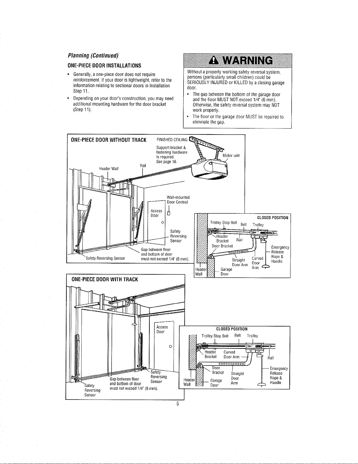
Planning(Continued)
ONE-PIECEDOORINSTALLATIONS
° Generally,aone-piece door does not require
reinforcement, [f your door is lightweight, refer tothe
information relating to sectionaldoors in Installation
Step 11.
° Dependingon your door's construction, you may need
additional mounting hardware for the door bracket
(Step 11).
Without a properly working safetyreversal system,
persons (particularly small children) could be
SERIOUSLYINJUREDor KILLED by aclosing garage
door,
• Thegap betweenthe bottom of thegarage door
andthe floor MUST NOTexceed1/4" (6 mm).
Otherwise,the safety reversal system may NOT
work properly,
• Therideror the garage door MUSTberepaired to
eliminate the gap.
-%
SafetyReversingSerlsor
/I
__ i allmounted
DoorControl
SafetyReversing
Sensor
Gapbetweenfloor
andbottomofdoor
mustnotexceedt/4" (6 ram).
ONE-PIECE DOOR WITH TRACK
Gapbetweerlrider S_rles_mg
Reversir_g }
Ser_soE
Header
andbottomof door Wall
mustnotexceedII4°(6ram).
5
CLOSEDPOSITION'
top Bolt Deft Trolley
Straight
Door Arm
Garage
Door
Emergency
Release
Rope &
Handle
CLOSEDPOSITION
TrotleyStopBolt Belt Trolley
I
Bracket DoorArm_ / t._ I:tai_
oooooopoooo/..,'
Door | -- Emergency
Y_///J " Bracket Straight Release
V_._ 6arage Door ROpe&
/./_ Door ,--m Handle
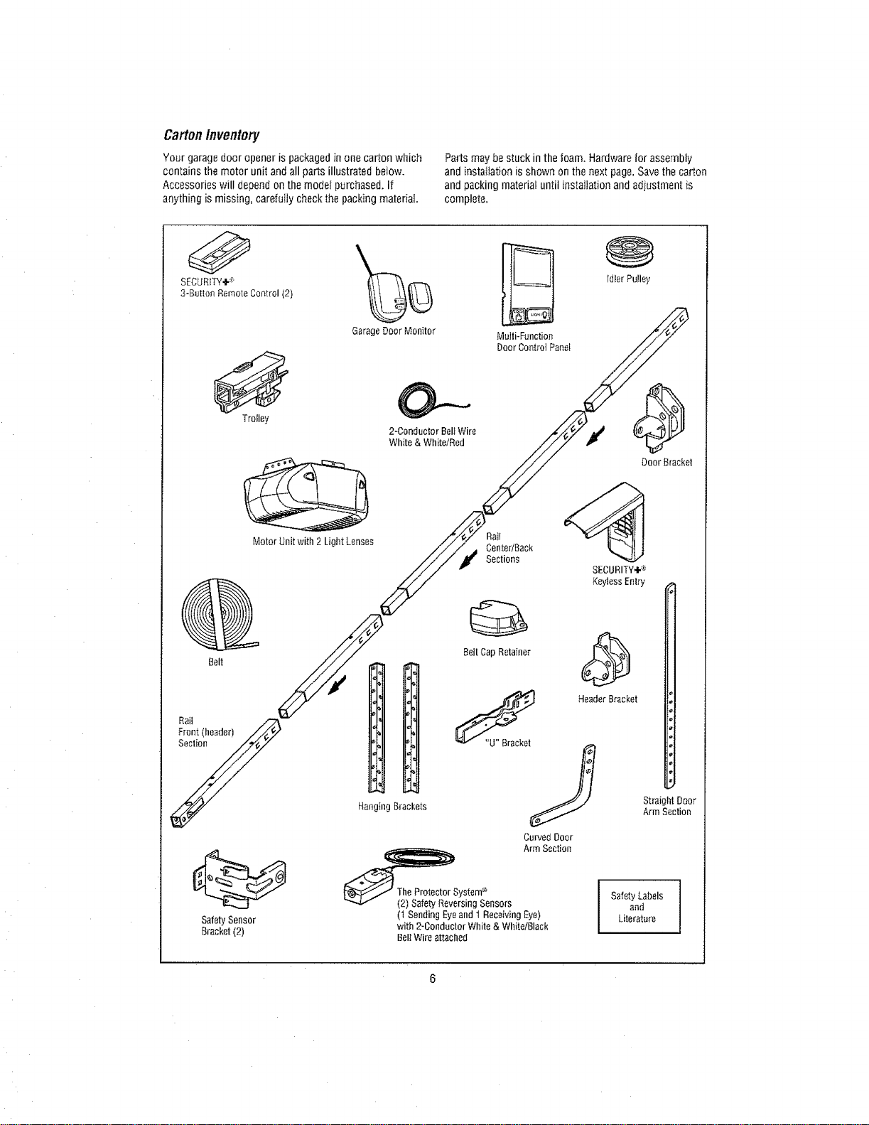
Carton Inventory
Your garage door opener is packaged in one carton which
contains the motor unit and all parts illustrated below.
Accessories will depend on the modet purchased, if
anything is missing, carefully check the packing material
Parts may be stuck in the foam. Hardware for assembly
and installation is shown on the next page. Savethe carton
and packing material until installation and adiustment is
complete.
SECURITY÷®
3-But[on Remote Control (2)
Garage Door Monitor Multi-Function
Door Control Panel
Belt
idler Pu!ley
Troiley
O----
2-Conductor Bell Wire
White & White/Red
Motor Unit with 2 Light Lenses
Door Bracket
Rail
Fron! (header) //_._/'
y
Safety Sensor
Bracket (2)
Hanging Brackets
_#rYStne_e nsors
(1 Sending Eyeand I Receiving Eye)
with 2-Conductor White & White/Black
BelI Wire attached
SECURITY÷®
Keyless Entry
Header Bracket
Straight Door
Arm Section
SafetyandLabels !
Literature
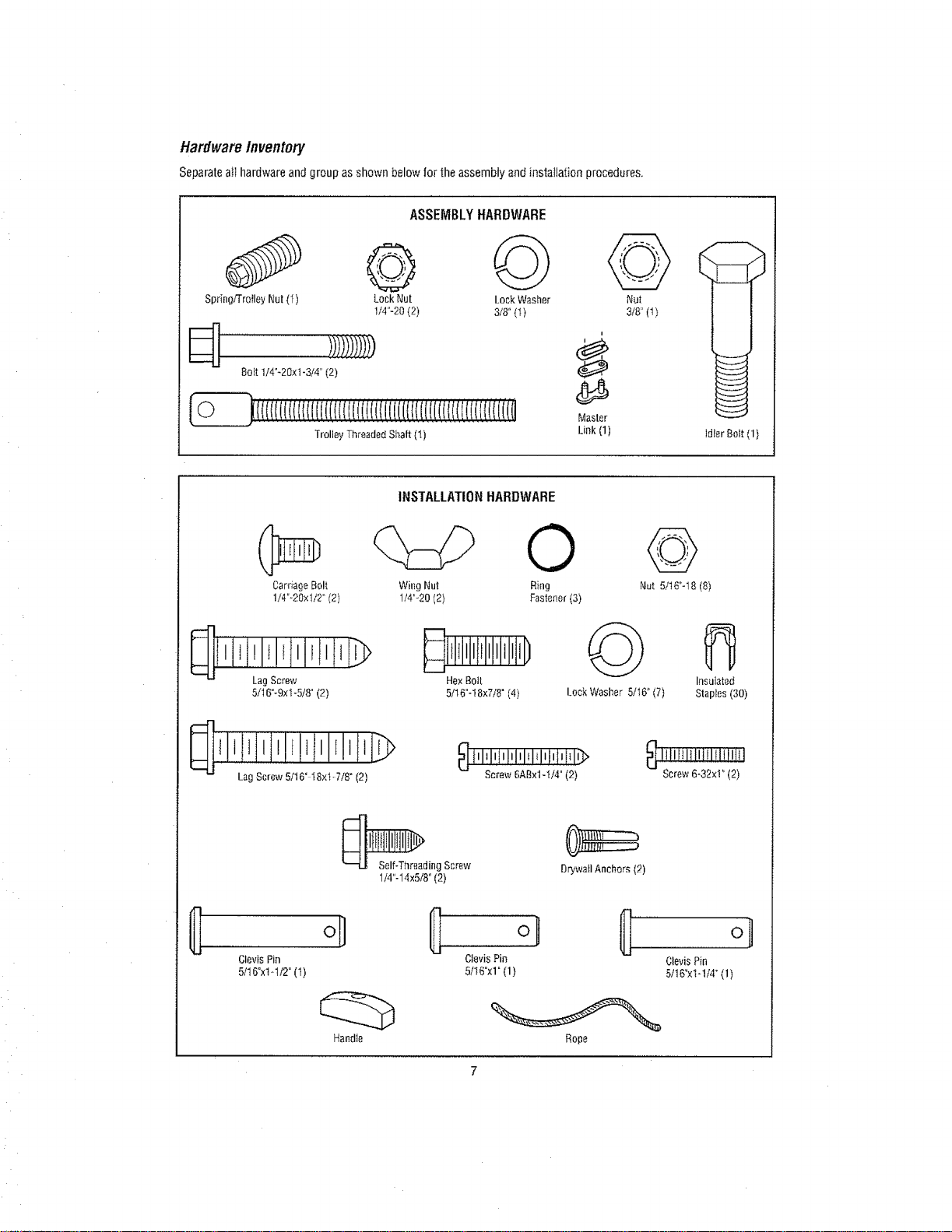
HardwareInventory
Separate a}I hardware and group as shown below for the assembly and installation procedures.
ASSEMBLYHARDWARE
Sp_ingiTroiley Nut (t) Lock Nut Lock Washer Nut
1/4"-20 (2) 318° (I) 3t8" (I)
8olt 1/4°-20xt -3/4" (2)
Trolley Threaded Sbalt (I)
i
Master
Link (1)
ld_erBolt (1)
INSTALLATIONHARDWARE
Carriage Bolt Wing Nut
1/4"o20xl/2" (2) 1/4"_20 (2)
©
R}ng
Fastener (3)
©
Nut 5/t6"-18 (8)
LagScrew
5/16"-9xl -5/8" (2)
Hex Bolt
5/16"-18x7/8" (4)
@
Lock Washer 5/t6 _(7)
Insulated
Staples (30)
JIlittltlrltl
Lag Screw 5116" 18xl-718" (2)
_ tllIlltllllll_l_lIlllIitl_
Screw 6ABx1-1i4" (2) Screw 6-32×1" (2)
_ding Screw
1/4"-14x5/8 °(2)
Drywa_IAnchors (2)
ClevisPin
51t6°x1-ti2°(t)
o]
Clevis Pin Clevis Pin
5/I 6"xl" (1) 5/16"xt-1/4 °(1)
Rope
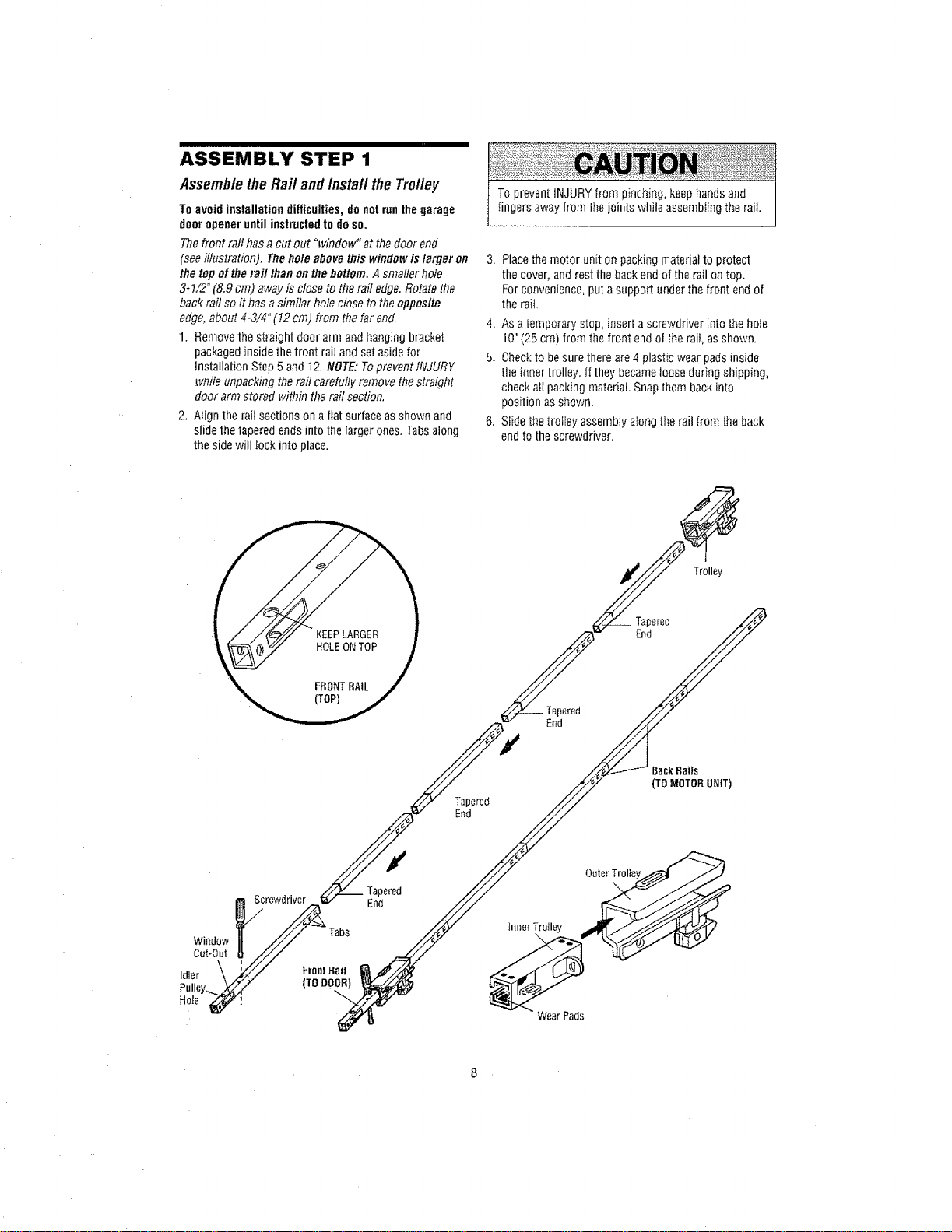
ASSEMBLY STEP 1
AssembletheRail and install the Trolley
To avoid installation difficulties, do notrunthe garage
door opener until instructedto do so.
Thefront rail has a cut out "window" at the door end
(see illustration). The hole above this window is larger on
the top ef the rail than on thebottom. Asmaller hole
3-1/2" (8,9 cm) away is close to the rail edge. Rotate the
back rail so it has a similar hole close to the opposite
edge, about 4-3/4" (I2 cm) from the far end.
1. Removethe straight door arm and hanging bracket
packaged inside thefront rail andset aside for
installation S_ep5and 12. NOTE: Toprevent lNJURY
while unpacking the rail carefully remove the straight
door arm stored within the raitsection,
2. Align the raii sections on a fiat surfaceas shown and
slide thetapered ends into thelarger ones. Tabs along
the side will lock into place,
To prevent iNJURYfrom pinching, keephands and
fingers away from the jointswhile assembling the rail,
3. Place the motor unit on packing material to protect
the cover, and rest the backend of therail on top.
For convenience, puta support under the front end of
the rait.
4. As a tempo_-arystop, inserta screwdriver into thehole
10" (25 cm) from tile front endol therail, as shown.
5. Checkto besure thereare 4 plastic wear padsinside
the inner [rolley. if they becameloose during shipping,
check all packing material. Snapthem backinto
position as sl;own.
6. Slide the trolley assembly aIong the rail from the back
endto the screwdriver.
Back Rails
(TO MOTORUNIT)
)ered
End
hmer Troiley
Wear Pads
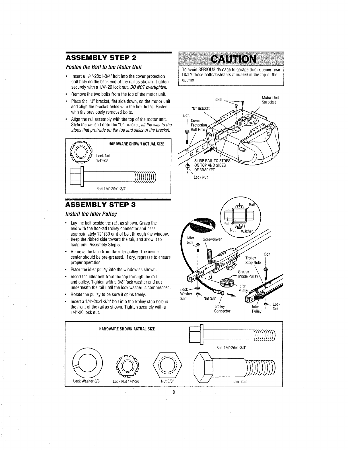
ASSEMBLY STEP 2
FastentheRail totheMotor Unit
• Inserta 1/4"-20xl-3/4" bolt into the cover protection
bolt hole on the backend of the rail as shown. Tighten
securely with a 1/4"-20 lock nut. DO NOTovertighten.
- Removethe two bolts from thetop of the motor unit.
• Placethe"U" bracket,flat side down, on themotor unit
andalign the bracket holes with the bolt holes. Fasten
with the previously removed bolts.
- Alignthe rail assembly with the top of the motor unit.
Slidethe raftend onto the "U" bracket,all the way to the
stops that protrude on thetop and sides of the bracket.
To avoid SERIOUSdamage to garagedoor opener, use
ONLYthose botts/fasteners mounted in the top of the
opener.
Boils Motor Unit
Sprocket
HARDWARESHOWNACTUAL SIZE
LockNut
1/4"-20
Bolt 1t4_-20x_-3/4"
ASSEMBLY STEP 3
Install theIdler Pulley
• Lay the belt beside the rail, asshown. Graspthe
endwith the hookedtrottey connector and pass
approximately 12" (30 cm) of be_tthrough the window.
Keepthe ribbed side toward the rail, and aitow it to
hang until Assembly Step 5.
. Removethe tapefrom the idler pulley. The inside
center should bepro-greased. If dry, regreaseto ensure
proper operation.
• Placethe idler puIley into the window as shown.
• Insert the idler holt from thetop through the rail
andpulley. Tighten with a 3/8" Iockwasher and nut
underneath the rail until the lock washer is compressed.
• Rotatethe pultey to besure it spins freely.
• Insert a t/4"-20xl-3/4" bolt into the trolley stop hole in
the front of therail as shown. Tighten securely with a
t/4"-20 lock nut.
Lock
Washer
3/8"
SLIDE RAIL TO STOP:
ONTOP AND SIDES
OFBRACKET
Lock Nut
Bolt
Trolley
StopHole
Grease '_
InsidePulley\
Trolley Id]er _ Nut
Connector Pulley
HARDWARESHOWNACTUALSIZE
Lock Washer 3/8"
@
LockNut1/4"-20
Nut 3/8°
Bolt114"-20xt-3/4"
I
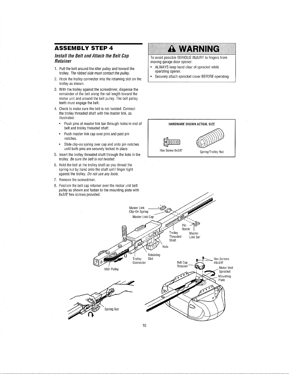
ASSEMBLY STEP 4
insta// theBe/tand AttachtheBe/t Cap
Retainer
1, Pullthe bdt around the idler puiiey and toward the
trolley. Theribbed side must contact thepulley.
2. Hook thetrolley connector into the retaining slot on the
trolley as shown.
3, With the trolley against the screwdriver, dispense the
remainder of the belt along the rail length toward the
motor unit and around the belt pulley. The belt pufley
teethmust engage the belt,
4. Checkto make surethe belt is not twisted. Connect
thetrolley threadedshaft with the master link, as
itIustrated:
• Push pins of master link bar through holes in endof
belt andtrolley threaded shaft.
- Push master link cap over pins and past pin
notches,
, Slide clip-on spring over cap and onto pin notches
until both pinsare secureIy locked in place.
5. Insert the trolley threadedshaft through the hole in the
trolley. Be sure the belt is not twisted.
6. Hold the belt at the trolley shaft as you thread the
spring nut by handonto the shaft untiI finger tight
against thetrolley. Donot useany tools,
7. Removethe screwdriver.
8, Position the be_tcap retainer over the motor unit belt
puIleyas shown andfasten to the mounting platewith
8x3/8" hex screws provided.
To avoid possibIe SERIOUSiNJURYto fingers from
moving garagedoor opener:
• ALWAYS keep handclear of sprocket while
operating opener,
• Securetyattach sprocketcover BEFOREoperating.
HARDWARESHOWNACTUALSIZE
HexScrew8x3/8° Spring/TrolleyNut
Master Link
Clip-On Spring
Master Link Cap
idler PuIIey
Spdng Nut
Trolley
Connector
Notch
Trolley Master
Threaded Link Bar
Shaft
Retaining
Slot _ Hex Screws
Belt Cap_ #8x3t8"
Retainer _l_J_l Motor Unit
,_ Sprocket
10
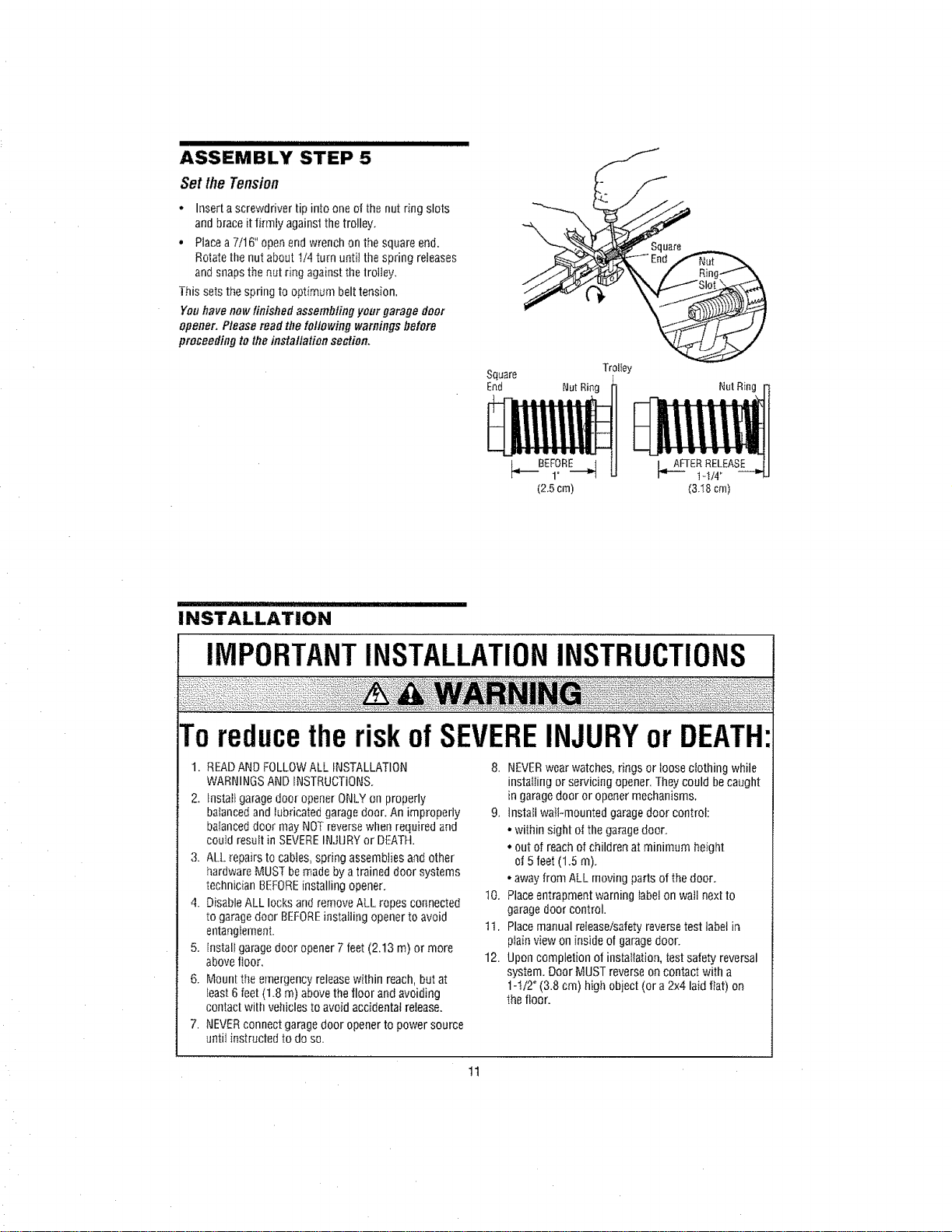
ASSEMBLY STEP 5
SetlheTension
• Inserta screwdriver tip into one of the nut ring slots
and brace it firmly against the trolley,
• Placea7/t6" open end wrench on the square end.
Rotatethe nut about II4 turn unfit the spring releases
andsnaps thenut ring against the lrolley.
This setsthe spring to optimum belt tension.
Youhave nowfinished assembling your garage door
opener. P/ease mad the fO//Owingwarnings bolero
proceeding to theinstallation section.
Square
End
Trolley
NutRing NutRing
INSTALLATION
IMPORTANTINSTALLATIONINSTRUCTIONS
Toreducetheriskof SEVEREINJURYor DEATH
1. READAND FOLLOWALL INSTALLATION
WARNINGSAND INSTRUCTIONS.
2. tnstattgarage door opener ONLYon properly
balancedand lubricated garage door. An improperly
balanceddoor may NOTreversewhen required and
could result in SEVEREINJURYor DEATH.
3. ALL _epairsto cables, spring assemblies and other
hardware MUST bemadeby atrained door systems
technician BEFOREinstalling opener.
4. Disable ALL locks andremove ALL ropes connected
to garagedoor BEFOREinstalling opener to avoid
entanglement.
5. Install garagedoor opener7 feet (2.13 m) or more
abovefloor,
6. Mount the emergency releasewithin reach, but at
least 6feet (1.8 m) above thefloor and avoiding
contactwith vehicles to avoid accidental release.
7. NEVERconnect garage door opener to power source
until instructed to do so.
8. NEVERwear watches,rings or loose clothing while
installing or servicing opener.They could becaught
in garagedoor or opener mechanisms.
9. lnstafi waiFmounted garagedoor control:
• within sight of the garagedoor.
* out of reach of children at minimum height
of 5feet (1.5 m).
- away from ALL moving parts of the door.
10. Placeentrapment warning label on wall next to
garage door control.
tl. Placemanual release/safetyreverse test labelin
plainview on inside of garagedoor.
12. Upon completion of installation, test safety reversal
system. Door MUST reverse oncontact with a
1-I/2 '_(3.8 cm) high object (or a 2x4 laid flat) on
the floor.
tl
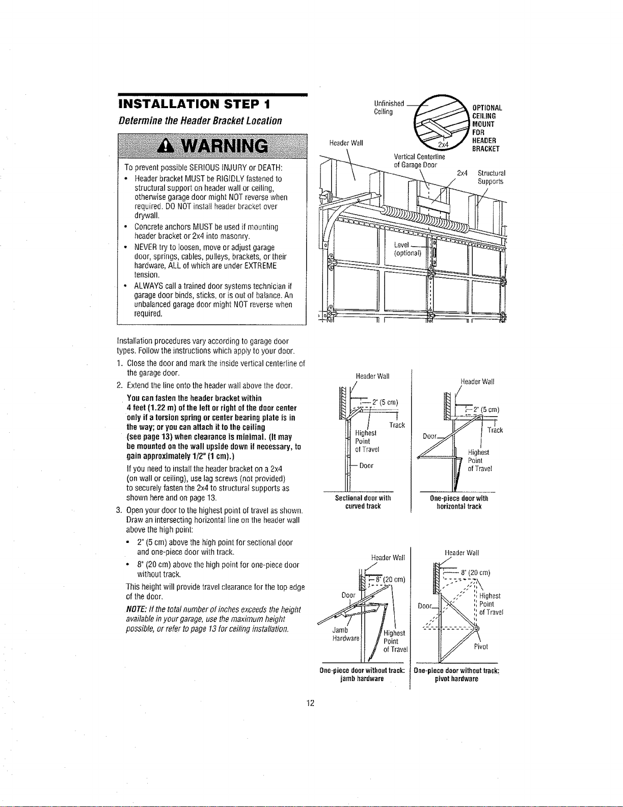
INSTALLATION"'"'S'T'E'P'"'I'"'
Determine theHeaderBracketLocation
To prevent possibie SERIOUSiNJURY or DEATH:
• Headerbracket MUST beRIGIDLYfastened to
structural support on headerwall or ceiling,
othe_ise garagedoor might NOTreverse when
required. DO NOTinslafl headerbracket over
drywall.
• Concreteanchors MUSTbe used if mounting
headerbracket or 2x4 into masonry.
o NEVERtryto Ioosen, move or adjust garage
door, springs, cables,pulleys, brackets, or their
hardware,ALL of which areunder EXTREME
tension.
• ALWAYS calla trained door systems technician if
garagedoor binds, sticks, or is out of batance.An
unbalanced garagedoor might NOTreverse when
required.
Header Wall
Unfinished_ OPTIONAL
Ceiling _J FoRMOuNTCEILING
HEADER
BRACKET
VerticalCenterline
of GarageDoor
2x4 Structural
Supports
installation procedures vary according to garagedoor
types. Followthe instructions which apply to your door.
t. Close the door and mark the inside vertical center[ine of
the garagedoor.
2. Extendthe line onto the headerwail abovethe door.
Yon canfasten the header bracketwithin
4 feet (1.22 m) of the left orright ofthe door center
only if a torsionspringor centerbearing plate isin
the way; or youcan attach it tothe ceiling
(see page 13) whenclearance is minimal. (It may
be mountedon the wall upside downif necessary,to
gain approximately1/2" (1 cm).)
tf you need to instali tile header bracket ona 2x4
(on wall or ceiling), use lag screws (not provided)
to securetyfasten the 2x4 to structural supports as
shown hereand on page13.
3. Openyour door to the highest poinl of travel as shown.
Draw an intersecting horizontal line m] the headerwall
above the high point:
• 2" (5 cm) above the high point for sectional door
and one-piecedoor with track.
* 8" (20 cm) above file high point for one-piece door
without track.
This height will provide travel clearance for the topedge
of the door.
NOTE:If the total number of inches exceeds theheight
availablein your garage,use themaximum height
possible, or refer topage 13for ceiling installation.
HeaderWall
/
i _2°(5cm)
Highest
Point
ol Travel
- Door
Sectional door with
curvedtrack
HeaderWail
/
/]'
Track
_ Highest
Paint
ofTrave_
One-piecedoorwith
horizontaltrack
HeaderWalt HeaderWail
Dog,AFt" :,Poi.t
.y% !i°f rav ,
II I H;ghest"-'-'--------------
_ar°warel{ _'Point I _ot
One_piecedoorwithouttrack:[ One-piecedoorwithouttrack;
jambhardware ] pivothardware
t2
INSTALLATION 2
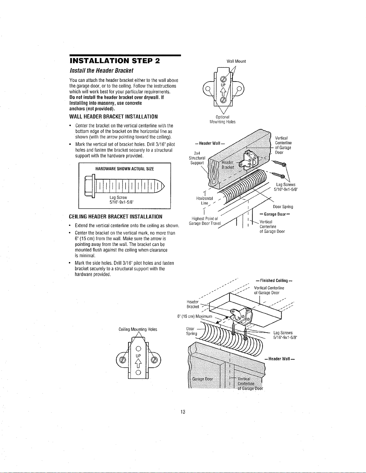
lnsta// the HeaderBracket
Youcanattachthe headerbracketeithertothewailabove
the garagedoor,ortotheceiling.Followtheinstructions
whichwill workbestforyourparticularrequirements,
Donotinstall theheaderbracketoverdrywall. If
installing intomasonry,useconcrete
anchors(notprovided).
WALLHEADERBRACKETINSTALLATION
• Centerthe bracket on thevertical centerline with the
bottom edgeof the bracket on the horizontal Iine as
shown (with the arrow pointing toward the ceiling).
• Markthe vertical set of bracket holes. Drill 3/t6 °pilot
holesandfasten the bracket securely to astructural
support with the hardware provided.
HARDWARESHOWNACTUALSIZE
Lag Screw
5/16°-9xt-5/8"
CEILINGHEADERBRACKETINSTALLATION
• Extendthe vertical centerline onto the ceiIing as shown.
• Centerthe bracket on thevertical mark, no more than
6°(15 cm) from thewalt. Make sure the arrow is
pointing away from the waft.The bracket can be
mounted flush against theceiIing when clearance
is minimal
- Markthe side holes, Drill 3/16" pilot holesand fasten
bracket securelyto astructural support with the
hardware provided,
Wall Mount
Optional
Mounting Holes
2x4
Structura_
Support
I
Horizontal /
Line/ ./
i
HighestPointof
GarageDoorTravel
Header
Bracket
6° (15 cm) M_
DoOr
Spring
Vertica}
Centerline
of Garage
Door
LagScrews
5/16"-9xl-5/8"
Door Spring
-- 6arago Door--
Vertical
Centertine
of GarageDoor
-- FinishedCeiling--
VerticalCenteriine
of GarageDoer
LagScrews
5/16"-9xl -5/8"
- Header Wall --
13
INSTALLATION STEP 3
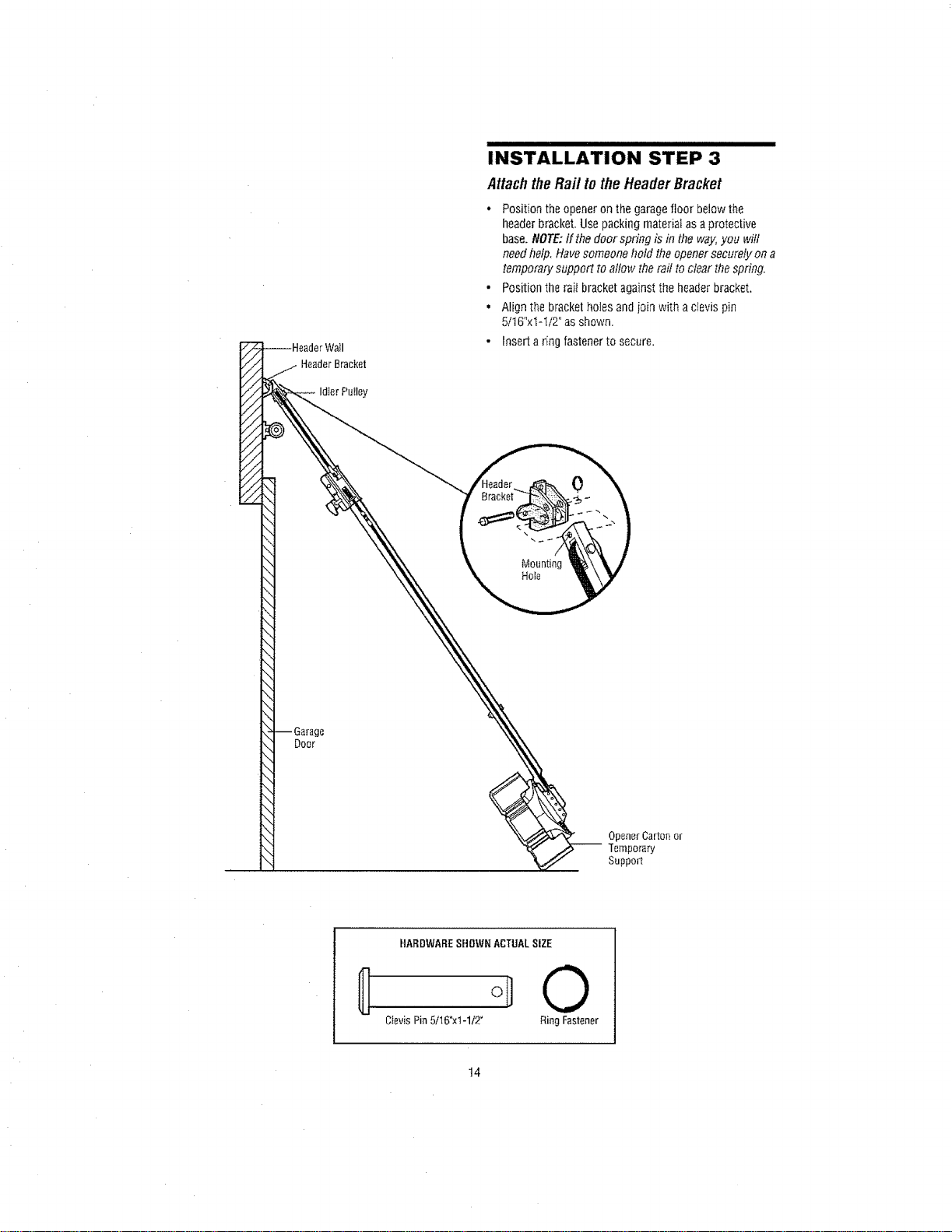
AttachtheRaft totheHeaderBracket
• Position the opener on the garagefloor below the
headerbracket. Use packing matedal as a protective
base. NOTE:if the door spn'ng is in the way,you will
needhelp, Havesomeone hold theopener securely on a
temporary support to allow the rail to clear the spring.
• Position the rait bracket against the headerbracket,
• Nigh the bracketholes and join with aclevis pin
5tt 6"xi-I/2" as shown.
• Insert a rino fastener to secure.
//
//
Idler PWIey
q
-- Garage
Doer
\1
\!
\1
\
Mounting
Hole
Opener Carton or
Temporary
Support
HARDWARESHOWNACTUALSIZE
0
CievisPin5/16°xi-1/2" RingFastener
t4
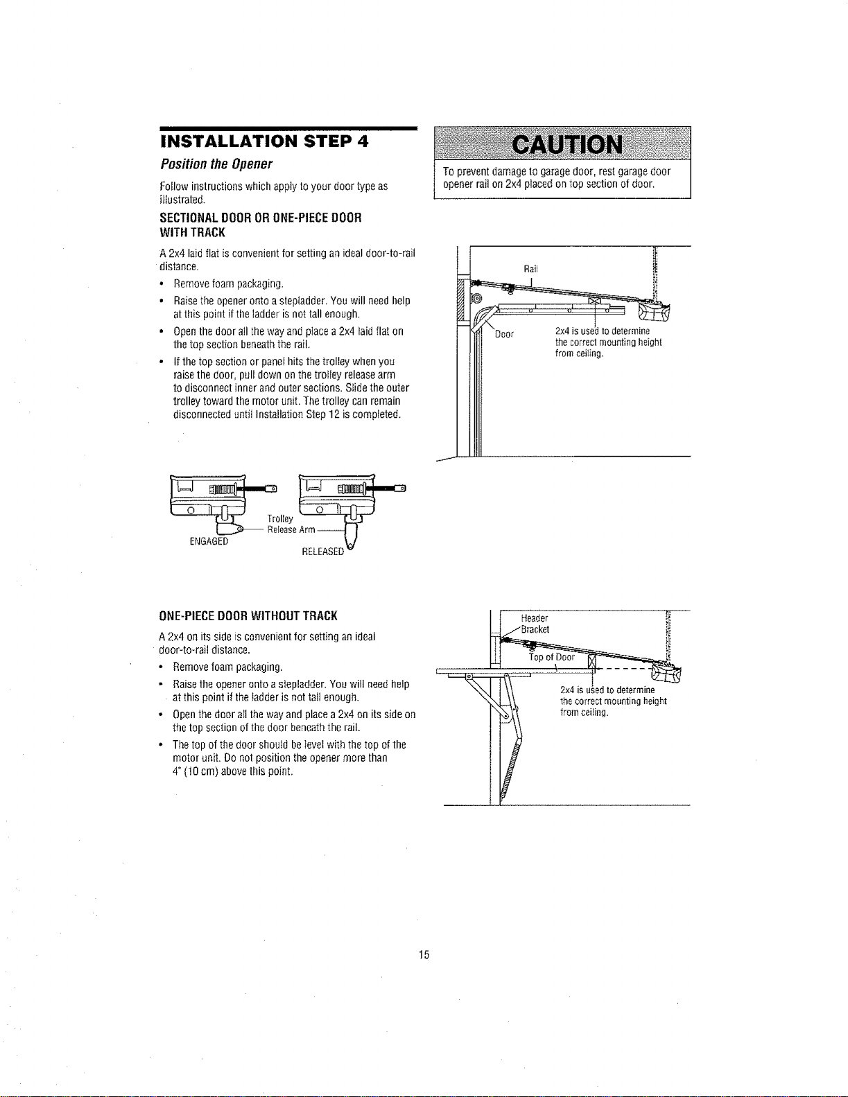
INSTALLATION STEP 4
Positionthe Opener
Follow instructions which apply to your door type as
illustrated,
SECTIONAL DOOR OR ONE-PIECE DOOR
WITH TRACK
A2x4 laid flat isconvenient for setting an idealdoor-to-rail
distance.
• Remove foam packaging.
• Raisethe opener ontoa stepladder. You will needhelp
atthis point if the [adderis not tall enough.
• Openthe door allthe way and place a2x4 [aidflat on
thetop section beneath the rail
• If the top section or panei hits the trolley whenyou
raisethe door, pull down onthe troliey releasearm
to disconnect inner and outer sections. Slidethe outer
trolley toward the motor unit. The trolley can remain
disconnected until Installation Step 12 is comp}eted.
To prevent damage to garagedoor, rest garagedoor
opener rail on 2x4 placed on top section of door.
Rail i
thecorrectmour_tingheight
fromcoifing.
lley
ReleaseArm-_ I
ENGAGED _.]
RELEASED
ONE-PIECEDOORWITHOUTTRACK
A 2x4 on its side is convenientfor setting an ideal
door-to-rail distance.
• Remove foam packaging.
, Raise theopener onto astepladder. You will need help
at this point if the ladder is not talt enough.
• Open thedoor ai[ the way and placea 2x4 on its sideon
the top section ofthe door beneath the rail.
• The top of the door should belevel with the top ofthe
motor unit. Do not position the opener more than
4" (10 cm) above this point,
It Header
2x4isusedtodetermine
thecorrectmountingheight
i from ceiling.
15
INSTALLATION sTEP'"'"5'"'''""''""'"""''
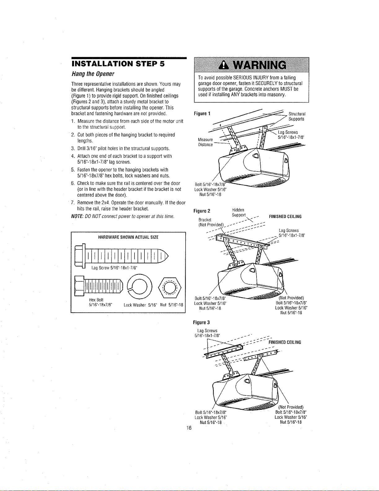
Hangthe Opener
Threerepresentative installations are shown. Yours may
be different. Hanging brackets should be angled
(Figure 1) to provide rigid support. Onfinished ceilings
(Figures2 and3), attacha sturdy metal bracket to
structural supports before installing the opener.This
bracket andfastening hardware are not provided.
1. Measure thedistance from each side of the motor unit
to the structural support.
2. Cut both piecesof the hanging bracket to required
lengths,
3. Drill 3/16" pilot holes in thestructural supports.
4. Attach one endof eachbracket to a support with
5/16"-18xl-7/8" lag screws.
5. Fastenthe openerto the hanging brackets with
5/t6"-18x7/8" hex bolts, lock washers and nuts.
6. Checkto makesure the ra[Iis centeredover the door
(or in linewith theheaderbracket ifthe bracket is not
centered above the door),
7. Remove the 2x4. Operatethe door manually. Ifthe door
hits the rail, raise the headerbracket.
NOTE: DONOTconnect po,_/erto opener at this time.
HARDWARE SHOWN ACTUAL SIZE
LagScrew5/16"d8xlqi8 °
...........D
HexBolt
5/16"-t8x7/8" LockWasher5/I6" Nut 5/16"-18
To avoid possibfe SERIOUSINJURY from afailing
garagedoor opener, fasten it SECURELYto structural
supports of the garage.Concreteanchors MUST be
used if installing ANY brackets into masonry.
Figure t Structural
)OFIS
Screws
5/t 6'-18xl 4/8"
Lock Washer 5/16"
Nut 5/t6°4 8
Figure 2
Bracket
(NotProvided)
Hidden
Support
FINISHEDCEILING
LagScrews
5116"-I8xl q/8 °
Bolt 5/16"q 8x7/8"
Lock Washer 5/t6"
Nut 5/16"-18
[NotProvided)
Bolt 5/16"-t8x7t8"
Lock Washer 5/I6"
Nut 5/t6q 8
Figure 3
Lag Screws
5/16"-t8xl -718"
16
Bolt 5/16"4 Bx7i8"
Lock Washer 5/16"
Nut 5it6"q8
(NotProvided)
Bolt5116"q8x7/8"
LockWasher5/16"
Nut5/16"q8
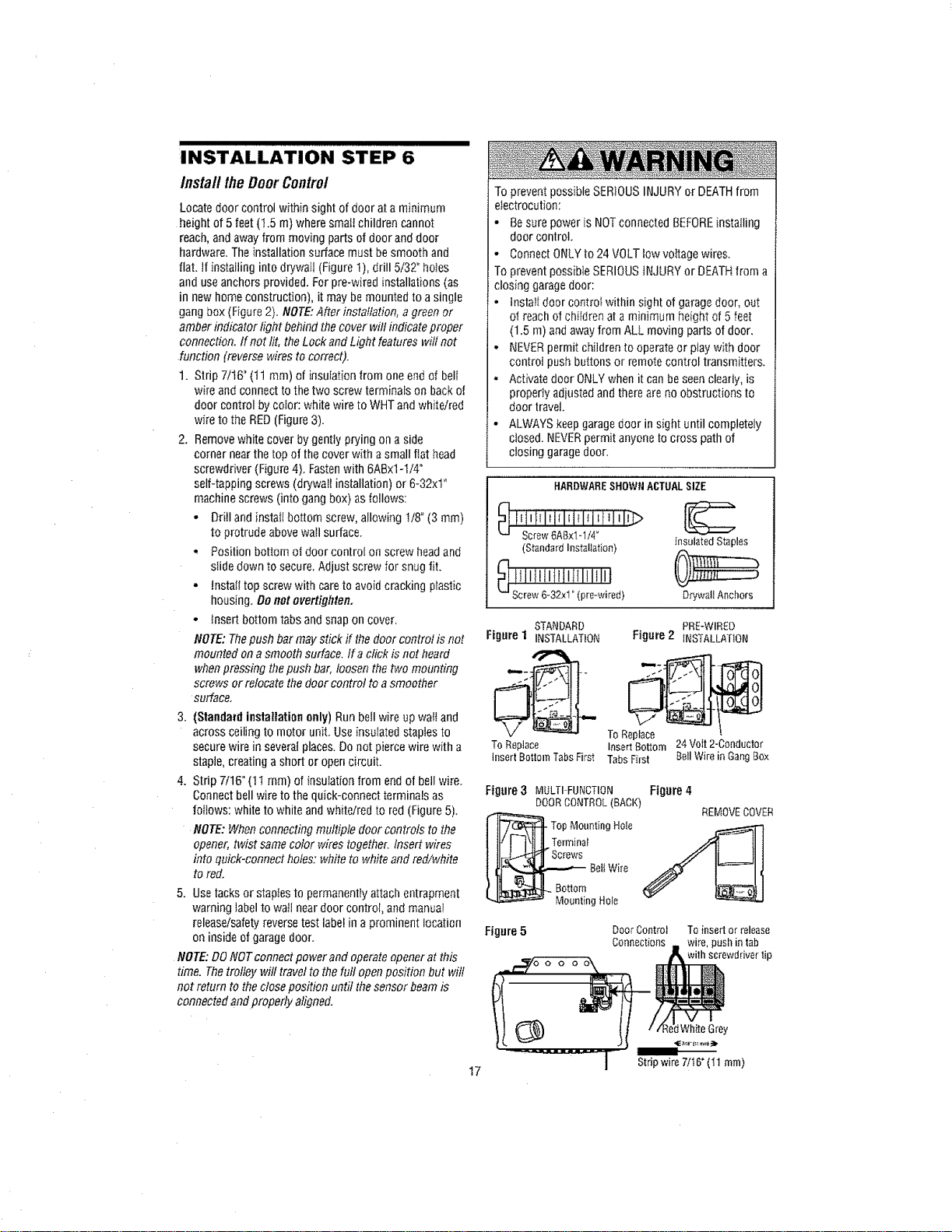
INSTALLATION STEP 6
InstalltheDoorControl
Locate door control within sight of doer at a minimum
height of 5 feet(t.5 m) where smafichildren cannot
reach, and away from moving parts of door and door
hardware. The installation surface must besmooth and
flat. if installing into drywall (Figure 1), drill 5/32" ho_es
and useanchors provided. For pre-wired installations (as
in new homeconstruction), it may bemounted to a single
gangbox (Figure 2). NOTE:After installation, a green or
amber indicator light behind thecover will indicate proper
connection. If not lit, the Lockand Light features will not
function (reverse wires to correct).
1. Strip 7/16" (tl ram) of insulation from one end of bell
wire and connect to the two screw terminals on back of
door control by color: white wire to WriT andwhite/red
wire to the RED(Figure 3).
2. Removewhite cover by gently prying on a side
corner nearthe top of thecover with asmall flat head
screwdriver (Figure 4), Fastenwith 6ABx1-ti4"
self-tapping screws (drywall installation) or 6-32xt"
machine screws (into gang box) as fOllOwS:
- Drill and instatl bottom screw, allowing I/8" (3 mm)
to protrude above wall surface.
• Position bottom ot door controI on screw headand
slide down to secure. Adjust screw for snug fit,
•tnstali top screw with care to avoidcracking plastic
housing. Denot overtighten,
- Insert bottom tabs and snap on cover.
NOTE: Thepush bar may stick if thedoor control is not
mounted on a smooth surface, ira click is not heard
when pressing thepush bar, loosen thetwo mounting
screws or relocate the door control to a smoother
surfacer
3. (Standard installation only) Run bell wire up wattand
across ceiling to motor unit. Use insulated staplesto
secure wire in several places. Donot pierce wire with a
staple,creating a short or opencircuit.
4. Strip 7/16" (11 ram) of insulation from end of bell wire.
Connectbell wire to the quick-connect terminals as
foflows: white to white andwhite/red to red (Figure5),
NOTE:When connecting multiple door controls tothe
opener, twist samecolor wires together. Insed wires
into quick-connect holes: white to white and red/white
to red.
5, Use tacks or staples to permanentfyattach entrapment
warning labelto wall neardoor control, and manuat
release/safetyreverse test labelin a prominent location
on inside of garagedoor,
NOTE: DONOTconnect power and operateopener at this
time. Thetrolley will travel to the full openposition but wilt
not return to the close position until the sensor beamis
connected and properly aligned.
17
To prevent possible SERIOUSINJURYor DEATHfrom
electrocution:
• Besure power is NOTconnected BEFOREinstalling
door control,
• Connect ONLYto 24 VOLTlow vottage wires.
To prevent possible SERIOUSiNJURY or DEATHfrom a
closing garagedoor:
• lnstalt door controI within sight of garage door, out
of reach of children at a minimum height of 5 feet
(1.5 m) and awayfrom ALL moving pads of door.
- NEVERpermit children to operate or play with door
control push buttons or remote control transmitters.
° Activatedoor ONLYwhen it can be seen clearly, is
property adjusted and there are no obstructions to
door travel.
• ALWAYS keepgaragedoor in sight until completely
closed. NEVERpermit anyone to cress path of
closing garagedoor.
HARDWARESHOWNACTUALSIZE
_ liiiiTi_ii_iiiiiliiJliiJ_
Screw6ABxlol/4°
(StandardInstallation)
InsulatedStaples
D_'wallAnchors
STANDARD PRE-WIRED
Figure 1 INSTALLATION Figure 2 _NSTALLATtON
ToReplace InsertBottom 24Volt2-Conductor
insertBottomTabsFirst TabsFirst BellWirein GangBox
Figure 3 MULTI FUNCTION Figure 4
DOORCONTROL(BACK)
REMOVECOVER
TOp Mounting Hole
Terrninat
Beli Wire
g Hole
Figure5
Door Control To insert or release
Connections wire, push in tab
with screwddver tip
:tWhiteGrey
Stripwire7/t6"(11 turn)
I III III IIIIIIIIIIIIIIIIIIIIIIIIIIIIIIIIIIIIII
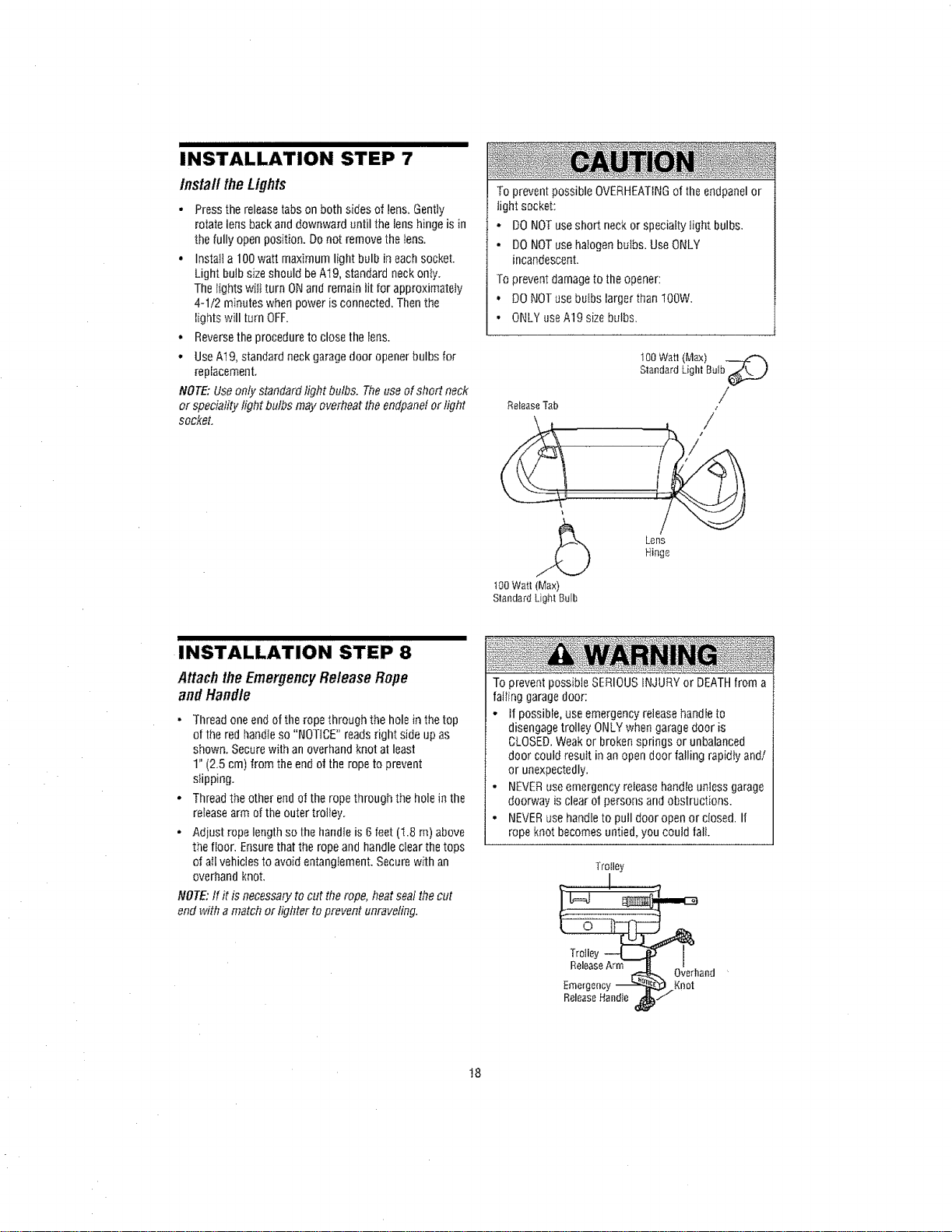
INSTALLATION STEP 7
install theLights
, Pressthe releasetabson both sides of lens_Gently
rotate lens backand downward until the lens hinge is in
the fully open position. Do not remove the tens,
• Insta;l a 100watt maximum light bulb in each SOCket.
Light bulb size should be A19, standard neckonly.
The fights will turn ONand remain lit for approximately
4-1/2 minutes when power is connected, Then the
lights will turn OFF.
• Reversethe procedure to close the fens,
• UseAt9, standard neck garagedoor openerbulbs for
replacement.
NOTE: Use only standard light butbs. Theuse of short neck
or speciality light bulbs may overheat the endpanelor light
socket.
To prevent possible OVERHEATINGof the endpanelor
light socket:
- DO NOTuse short neckor specialty light bulbs.
o DO NOTuse hatogen bulbs. Use ONLY
incandescent.
To prevent damageto the opener:
• DONOTuse buIbs largerthan IOOW.
• ONLYuseA19 sizebulbs.
(Max)
100WattLightButb__.,,)
Standard
ReleaseTab /
z
i
/_ Ler_s
Hinge
t00Watt(Max)
StandardLightBulb
INSTALLATION STEP 8
Attachthe Emergency ReleaseRope
and Handle
• Thread one endof the rope through the hole in the top
o[ the red handleso "NOTICE" reads right side upas
shown. Securewith an overhand knot at least
1" (2.5 cm) from the end o1the rope to prevent
slipping.
• Thread the other end of the rope through the hole in the
releasearm of the outer trolley.
o Adjust rope length so the handle is 6 feet (I.8 m) above
the floor. Ensurethat the rope and handleclear thetops
of all vehicles to avoid entanglement. Secure with an
overhand knot.
NOTE:tf it is necessary to cut the rope, heatsealthe cut
end with a match or lighter to prevent unraveling.
To prevent possible SERIOUSINJURYor DEATHfrom a
failing garagedoor:
o if possible, use emergencyrelease handleto
disengage trolley ONLYwhen garage door is
CLOSED.Weakor broken springs or unbalanced
door could result in an opendoor falling rapidly and/
or unexpectedly.
• NEVERuseemergency releasehandte unless garage
doorway is clear of personsand obstructions.
• NEVERusehandle to pull door open or closed. If
rope knot becomes untied, you could fall.
Trolley
_and
!8
I II IIIIIII IIIIIIII IIIIIIIIIIIIIIII
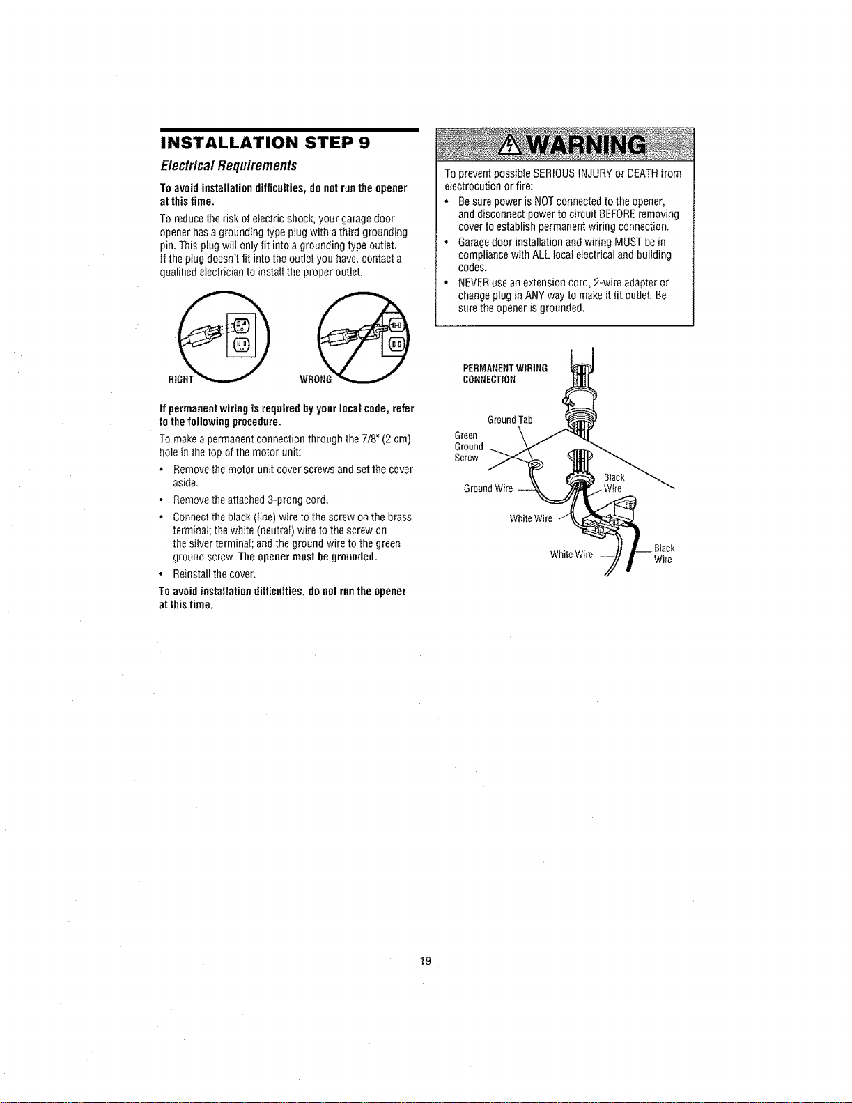
INSTALLATION STEP 9
ElectricalRequirements
To avoid installation difficulties, do notrun theopener
at thistime.
To reducethe risk of electric shock, your garagedoor
opener has a grounding type plug with a third grounding
pin. This plug wilt only fit into a grounding type outlet.
it the plug doesn't fit into the outlet you have,contact a
qualified electrician to install the proper outlet.
If permanentwiring isrequired by yourlocal code, refer
to the following procedure.
To make a permanent connection through the 7/8" (2 cm)
hole in the top of the motor unit:
• Removethe motor unit cover screws and set the cover
aside.
- Removethe attached 3-prong cord.
, Connectthe black (line) wire to the screw on the brass
terminal; thewhite (neutral) wire to the screw on
the silver terminal; and the ground wire to the green
ground screw.The opener mustbegrounded.
• Reinstallthe cover,
To avoid installation difficulties, donotrun the opener
at thistime.
To prevent possibte SERIOUSINJURY or DEATHfrom
electrocution or fire:
• Besurepower is NOTconnected to theopener,
anddisconnect power to circuit BEFOREremoving
cover to establish permanent wiring connection.
• Garagedoor installation and wiring MUSTbe in
compliance with ALL Iocai electrical and building
codes.
• NEVERuseanextension cord, 2-wire adapteror
changeplug in ANYway to make it tit outlet. Be
surethe opener is grounded.
PERMANENTWIRING
CONNECTION
Ground Tab
Green
Ground
Screw
Ground Wire
White Wire
WhiteWire 7 i _iarCek
!9
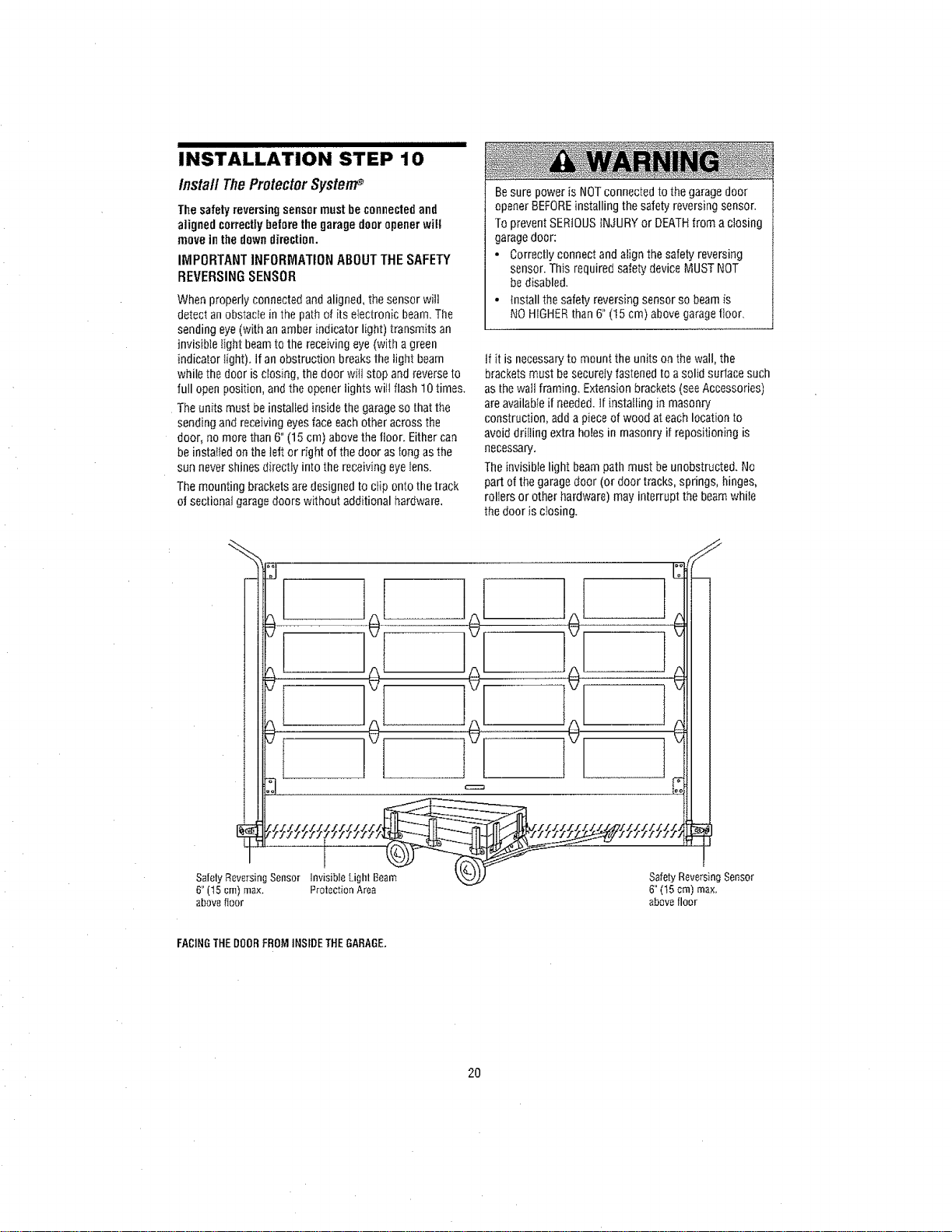
INSTALLATION STEP'"'I'O""''""'"""""'
Install TheProtectorSystem_
The safetyreversingsensormustbe connectedand
aligned correctlybefore the garage dooropenerwill
move inthe downdirection.
IMPORTANTINFORMATIONABOUTTHESAFETY
REVERSING SENSOR
When properly connected andaligned, the sensor will
detect anobstacfein the pathof its electronic beam. The
sending eye(with an amber indicator light) transmits an
invisible tight beamto the receiving eye (with a green
indicator fight). Ifan obstruction breaks the light beam
while the door is closing, the door will stop andreverse to
full open position, andthe opener lights wilt flash 10 times.
The units must be installed inside thegarageso that the
sending and receiving eyesface each other across the
door, no more than 6" (15 cm) abovethe floor. Either can
beinstalled on the teftor right of thedoor as long as the
sun never shines directly into the receiving eyelens.
The mounting brackets are designedto clip onto thetrack
of sectiona4garagedoors without additional hardware,
Besure power isNOTconnected to the garagedoor
openerBEFOREinstalling the safety reversingsensor.
To prevent SERIOUSiNJURYor DEATHfrom a closing
garagedoor:
• Correctly connect and align the safety reversing
sensor. This required safety device MUSTNOT
be disabled.
• {nstall the safety reversing sensor so beam is
NO HIGHERthan 6" (15 cm) abovegaragefloor_
if it is necessaryto mount the units on the wall, the
brackets must be securely fastened to asolid surtace such
as thewall framing. Extension brackets (seeAccessories)
areavailable if needed, tf installing in masonry
construction, adda pieceof wood at each location to
avoiddriIling extra holes in masonry if repositioning is
necessary,
Theinvisible light beampath must beunobstructed. No
part of the garagedoor (or door tracks, springs, hinges,
rollers or other hardware) may interrupt the beamwhile
thedoor is closing.
!
SafelyReversingSensor InvisibleLighlBeam
6"(15cm)max. ProtectionArea
abovefloor
Safety Reversing Sensor
6" (15 crn) max,
above floor
FACINGTHE DOORFROM INSIDETHE GARAGE,
2O
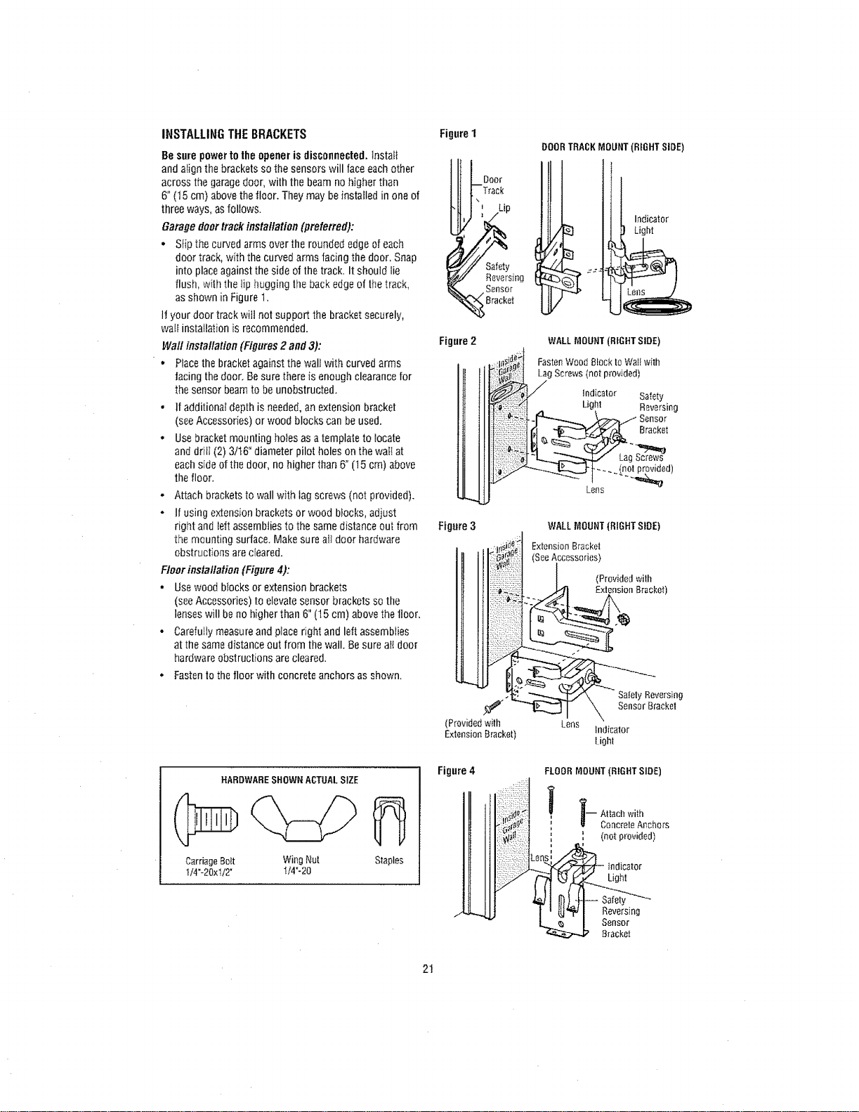
INSTALLINGTHEBRACKETS
]Besure powerto the opener is disconnected.InstaE_
andalign the brackets so thesensors will face each other
across the garagedoor, with the beam nohigher than
6" (15 cm) abovethe floor. They may beinstalled in one of
three ways,as follows.
Garage doortrackinstallation (preferred):
• Stip the curved arms over the rounded edgeof each
door track, with the curved arms facing the door, Snap
into placeagainst the side of the track. It should lie
flush, with the tip hugging the backedge of thetrack,
as shown in Figure 1,
If your door track will not support the bracket securely,
waif installation is recommended.
Wall installation(Figures 2 and 3):
• Placethe bracket againstthe wali with curved arms
facing the door. Be sure there is enough clearance for
the sensor beam to be unobstructed,
• If additional depth is needed,an extension bracket
(seeAccessories) or wood blocks can be used,
• Usebracket mounting ho}es as atemplate to tocate
anddrift (2)3It6" diameter pilot holes on the wal{at
each sideof the door, no higher than6" (15 cm) above
the floor,
• Attach brackets to wall with tagscrews (not provided).
- If using extension brackets or wood blocks, adjust
right and left assemblies to the same distance out from
the mounting surface. Makesure all door hardware
obstructions are cleared.
Floor installation (Figure4):
• Usewood blocks or extension brackets
(seeAccessories) to elevatesensor brackets so the
lenses will be no higher than 6" (15 cm) abovethe floor,
• Carefully measure andplace right and left assemblies
at the same distance out from the wall. Be sure aI_door
hardware obstructions are cleared.
° Fastento thefloor with concreteanchors as shown.
HARDWARESHOWNACTUALSIZE
CarriageBdt WingNut Staples
1/4"-20x112" 1t4"-20
Figure1
Door
Safety
Reversing
Sensor
Bracket
Figure 2
Figure 3
(Providedwith
ExtensionBracket)
Figure 4
DOORTRACKMOUNT (BIGHT SIDE)
Indicator
Light
WALLMOUNT (BIGHT SIDE)
FastenWood Block to Wall with
LagScrews (not provided)
Indicator Safety
Light Reversing
Sensor
Bracket
WALL MOUNT (RIGHT SLOE)
Extension Bracket
See Accessories)
(Provided with
Extension Bracket
Safely Reversing
Sensor Bracket
Lens
h_dicator
Light
FLOORMOUNT(RIGHTSIDE)
' ' (notprovided
k i
indicator
Light
Reversing
Sensor
Bracket
2!
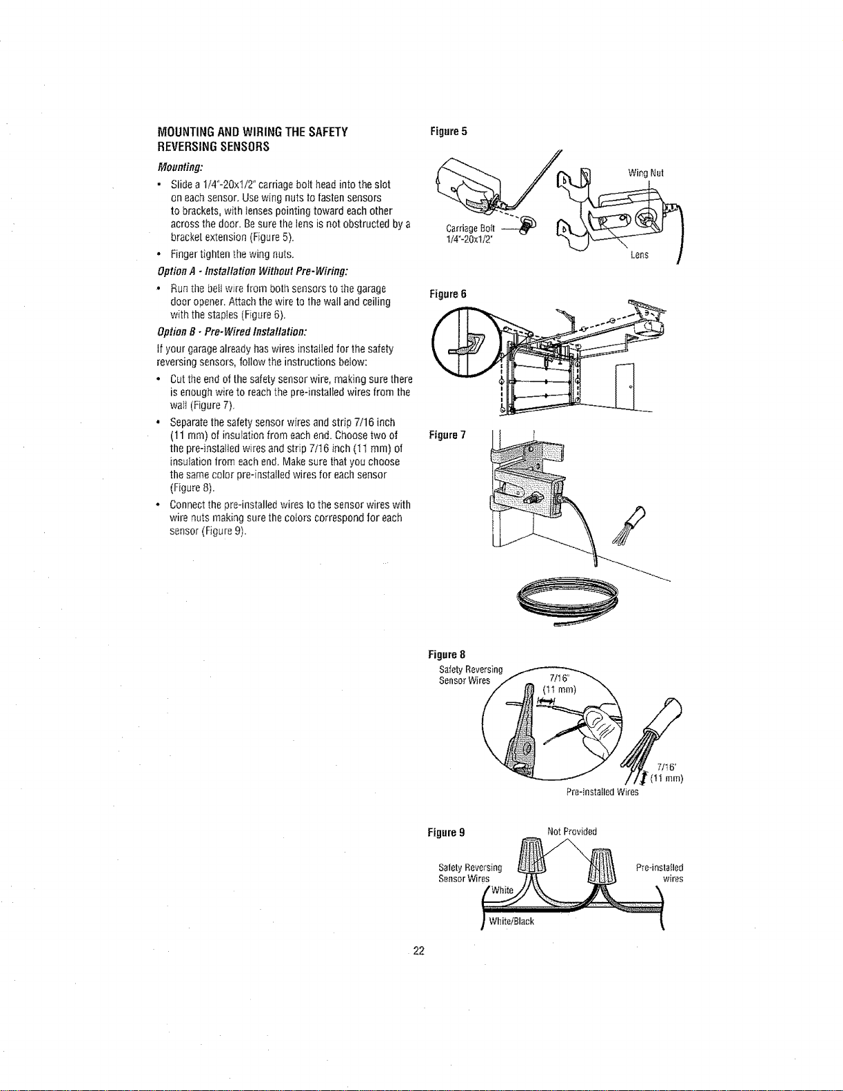
MOUNTINGANDWIRINGTHESAFETY
REVERSINGSENSORS
Mounting:
• Slidea t/4"-20xl/2" carriage bolt head into the slot
oneach sensor. Usewing nuts to fasten sensors
to brackets, with Iensespointing toward each other
across the door. Be sure the Jensis not obstructed by a
bracket extension (Figure 5).
° Fingertighten the wing outs.
Option A - Installation Without Pre-Wiring:
- Runthe belt wire from bOtt_sensors to the garage
door opener.Attach the wire to thewall and ceiling
with the staples (Figure6).
Option B - Pro-Wired Insta!lation:
if your garagealready haswires installed for the safety
reversing sensors, follow the instructions below:
• Cut theend of the safetysensor wire, making sure there
is enough wire to reachthe preqnstalied wires from the
waii (Figure 7).
• Separatethe safety sensor wfres andstrip 7/16 inch
(11 ram) of insulation from each end. Choosetwo of
the pre-installed wires and strip 7/16 inch (11 ram) of
insulation from each end. Makesure thatyou choose
the samecolor preqnstafled wires for each sensor
(Figure 8).
• Connectthe pre-installed wires to the sensor wires with
wire nuts making sure the Colors correspond for each
sensor (figure 9).
Figure5
Carriage 80It
1/4"-20xl/2"
Figure6
Figure 7
Wing Nut
Lens
Figure 8
SafetyReversing_)_7it 6_
SensorWires
(
Pre-lnstaBledWires
Figure 9 Not Provided
Safety Reversing Pre-instaIled
Sensor Wires wires
I White/Black
22
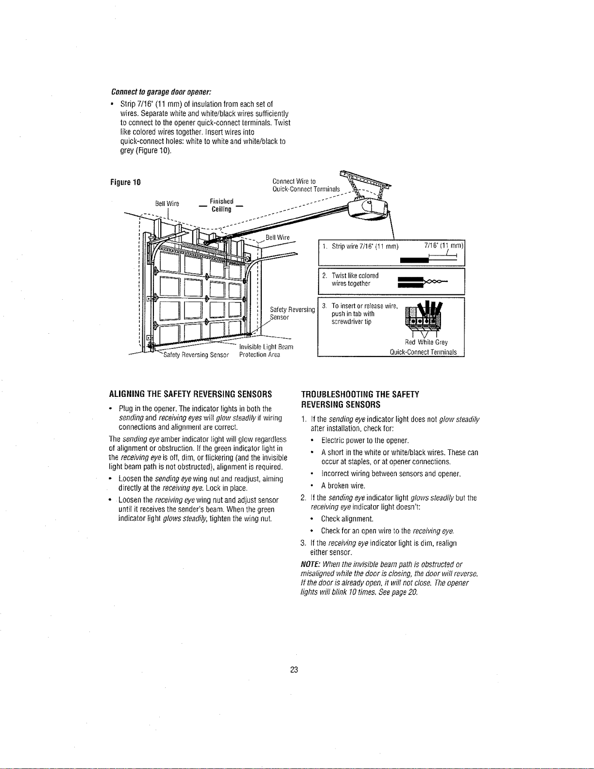
Connectto garagedoor opener:
• Strip 7/16" (11 mm) of insulation from eachset of
wires. Separatewhite andwhite/black wires sufficiently
to connect to the opener quick-connect terminals. Twist
like colored wires together. Insert wires into
quick-connect holes: white to white andwhite/black to
grey (Figure 10).
Figure10
BellWire Finished
i Ceiting
Safety Reversing Sensor
ConnectWireto
Quick*ConnectTerminals
Safety Reversing
Sensor
invisible Light Beam
Protection Area
1. Stripwire7/16"(11rnm)
2. wistlikecolored
wirestogether
3. Toinsertor releasewir_,
pushintabwith
screwdrivertip
RedWhiteGrey
Quick-ConnectTenninals
ALIGNINGTHESAFETYREVERSINGSENSORS
* Plug in the opener.The indicator lights in both the
sending and receiving eyeswiil glow steadily ifwiring
connections and alignment are correct.
The sending eyeamber indicator light will gtow regardless
of alignment or obstruction. Ifthe green indicator light in
"thereceiving eyeis off, dim, or flickering (and the invisible
light beam path is not obstructed), alignment is required.
• Loosen the sending eyewing nutand readjust, aiming
directly at the receiving eye.Lock in place.
• Loosen the receiving eyewing nut andadiust sensor
until it receivesthe sender's beam, Whenthe green
indicator light glows steadily, tightenthe wing nut.
TROUBLESl-IOOTING THE SAFETY
REVERSING SENSORS
1. If the sending eye indicator light does not glow steadily
after installation, check for:
• E_ectricpower to the opener.
• A short in the white or white/black wires. These can
occur at staples, or at openerconnections.
• incorrect wiring between sensors andopener,
• A broken wire.
2. If the sending eyeindicator light glows steadilybut the
receiving eye indicator light doesn't:
- Checkalfgnment.
* Checkfor an open wire to the receiving eye.
3, If the receMng eyeindicator light isdim, realign
either sensor.
NOTE: When theinvisible beam path is obstructed or
misaligned while the door is closing, the door will reverse.
If thedoor is already open, fl wilt not close. Theopener
lights will blink 10times. Seepage 20,
23
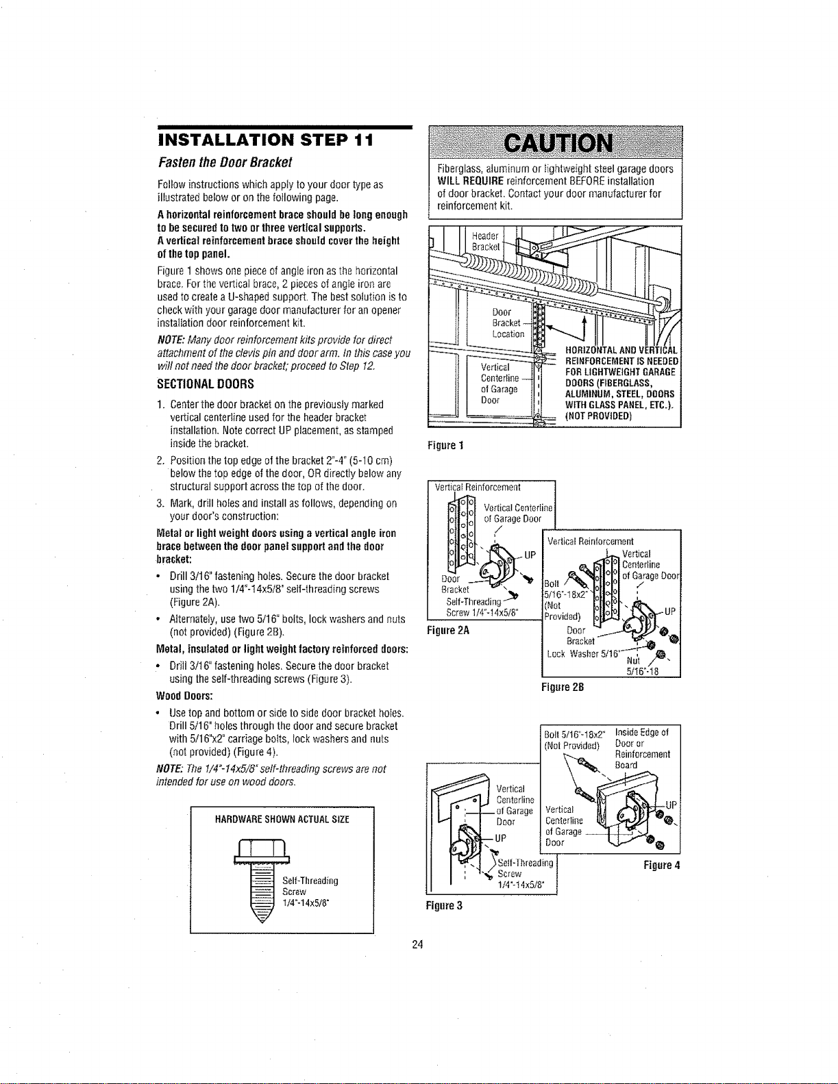
INSTALLATION STEP 11
FastentheDoorBracket
Follow instructions which apply to your door type as
illustrated below or on thefollowing page,
A horizontalreinforcementbraceshouldbe longenough
to be securedto two or threevertical supports.
A vertical reinforcement brace shouldcoverthe height
of thetop panel.
Figuret shows one pieceof angle iron as the horizontal
brace, For thevertical brace, 2 pieces of angle iron are
used to create a U-shaped support. The best sotution is to
check with your garagedoor manufacturer for anopener
installation door reinforcement kit.
NOTE:Many door reinforcement kits provide for direct
attachment of the clevis pin anddoor arm. In this caseyou
will not needthe door brackefiproceed to Step 12.
SECTIONAL DOORS
!. Centerthe door bracket on the previously marked
vertical centefline used for the headerbracket
installation. Notecorrect UPplacement, as stamped
inside the bracket.
2. Position the top edgeof the bracket 2"-4" (5-10 cm)
below the top edge ofthe door, ORdirectiy below any
structural support across thetop of thedoor.
3. Mark, drill holesand install as follows, depending on
your door's construction:
Metal or light weight doors usinga vertical angle iron
bracebetweenthe door panel supportandthe door
bracket:
• Drill 3/16" fastening ho_es.Secure the door bracket
usingthe two 1/4"-14x5/8" self-threading screws
(Figure2A).
• Alternately, usetwo 5/16" bolts, lock washers and nuts
(not provided) (Figure 2B).
Metal, insulated or light weight factoryreinforced doors:
• Drill 3t16" fastening holes, Secure the door bracket
using the self-threading screws (Figure 3).
Wood Doors:
• Usetop and bottom or side to side door bracket hobs.
Drill 5/16" holes through the door and secure bracket
with 5/16"x2" carriage botts, rock washers and nuts
(not provided) (Figure 4).
NOTE: The li4"-14x5/8" self-threading screws are not
intended for use on wood doors.
HARDWARESHOWNACTUALSIZE
Self_Threading
Screw
I/4"-14x5/8"
Fiberglass,aluminum or lightweight steel garagedoors
WILL REQUIREreinforcement BEFOREinstallation
of door bracket. Contact your door manufacturer for
reinforcement kit.
Figure 1
Verticaf Reinforcement
Vertical Centeriine J
of GarageDoor |
/
J.
D
Bracket
Self-Threadirlg -_
Screw 1/4"-14×5tB"
Figure2A
(NOT PROVIDED)
Vertical
Centefline
Lock
5/16"-18
Figure28
Bolt5116"-18x2" InsideEdgeof
(NotProvided) Dooror
Reinforcement
Board
Figure4
24
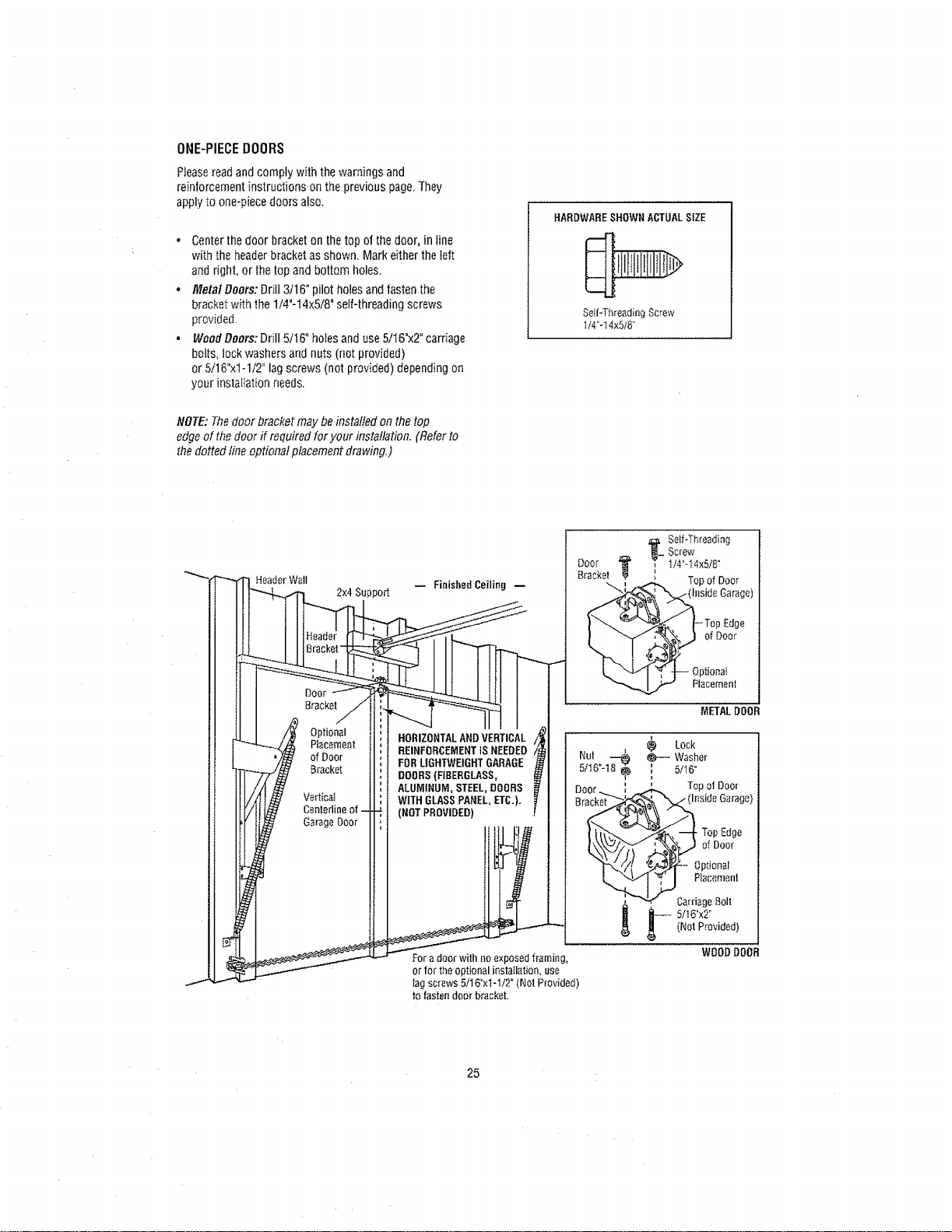
ONE-PIECEDOORS
Pleasereadandcomplywiththewarningsand
reinforcementinstructionsonthe previouspage,They
applytoone-piecedoorsalso.
- Centerthe door bracket on the top of the door, in line
with the headerbracket as shown. Mark either the left
and right, or the top andbottom holes
• Metal Doors: Drill 3/16" pilot holesand fasten the
bracket with the 1/4"-t 4x5/8" self-threading screws
provided
• Wood Doors: Drill 5/16" holes anduse 5/16'x2 °carriage
bolts, lock washers and nuts (not provided)
or 5/16"x1-1/2" lag screws (not provided) depending on
your [nsta%t[onneeds
NOTE: Thedoor bracket may beinstalled on thetop
edgeof the door if required for your installation. (Refer to
the dotted line optiona! placement drawing.)
HARDWARESHOWNACTUALSIZE
Self-Thread}ng Screw
I/4"-14x5/8"
HeaderWail
2x4Support
Door
HORIZONTALANDVERTICAL
REINFORCEMENTtSNEEDED
FORLIGHTWEIGHTGARAGE
DOORS(FIBERGLASS,
ALUMINUM,STEEL,DOORS
WITHGLASSPANEL,ETC.).
(NOTPROVIDED)
For a door with no exposed framing,
or for the optional installation, use
__ Self-Threading
Screw
BracketO°°r_ _ 1/4"-14x5/8°
Top of Door
Edge
of Door
lag screws 5/16°xl -1I2" (Not Provided)
to fastendoor bracket
25
iiiiiiiiiiiiiiiiiiiiiiiiiiiiiiiiiiiinln nil i nllnl i
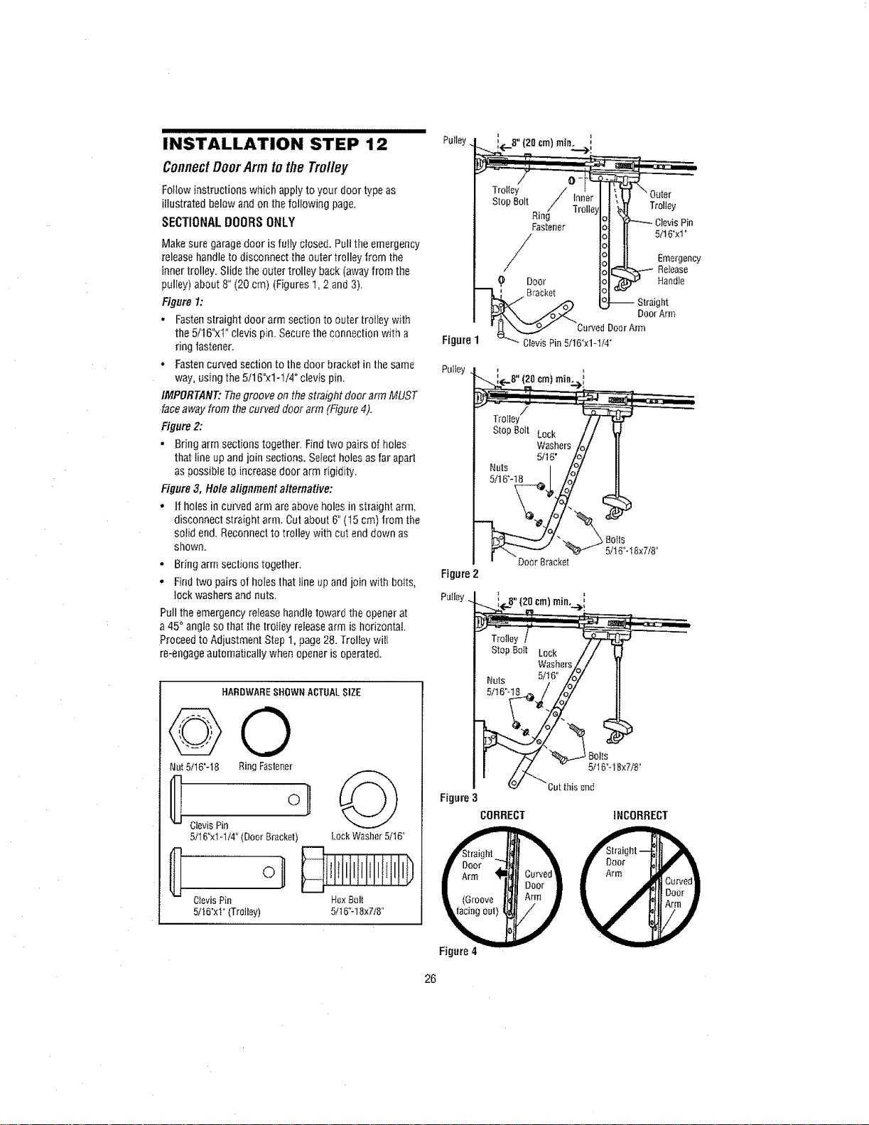
INSTALLATION STEP 12
ConnectDoorArm tothe Trolley
FoItowinstructions which apply to your door type as
illustrated below andon thefollowing page,
SECTIONAL DOORS ONLY
Make sure garagedoor is fully closed. Pult the emergency
release handleto disconnect theouter trolley from the
inner trolley. Slide the outer trolley back (awayfrom the
pulEey)about 8" (20 cm) (Figures1,2 and 3).
Figure I:
. Fastenstraight door arm section to outer trofleywith
the 5/16"xi" clevis pin. Securethe connection with a
ring fastener.
• Fastencurved section to thedoor bracket in the same Pulley
way, using the 5/16"xl-1/4" clevis pin,
IMPORTANT: Thegroove on thestraight door arm MUST
face away from the curved door arm (Figure 4).
Figure 2:
• Bring arm sections together. Ffnd two pairs of holes
that fine upand join sections. Select holes as far apart
as possible to increase door arm rigidity,
Figure 3, Hole alignment alternative:
• If holes in curved arm are above holes in straight arm,
disconnect straight arm. Cut about 6"(t5 cm) from the
solid end. Reconnect to trolley with cut enddown as
shown.
• Bring arm sections together.
° Find two pairs of holes that line upand join with bolts,
lock washers and nuts. Putiey
Pull the emergencyrelease handletoward the opener at
a 45°angie so that the trotiey releasearm is horizontal.
Proceedto Adjustment Step 1,page28. Trolley will
re-engageautomatically when opener is operated.
HARDWARESHOWNACTUALSIZE
@0
Nut5/t6"-I8 RingFastener
ClevisPin
5/16"xIol/4"(Door8racket) LockWasher5/t6"
CIevisPin HexBolt
5/!6"x1"(Trolley) 5/16_-18x7t8"
om)min.
Trolley/
StopBoit Lock
Washers
5116"
Nuts I
5/16"-18 _J
' DoorBracket
Figure2
Figure
Figure4
Boils
5/16"-18x7/8"
;(..B"(2oor.)mi.._i
sto BottLouk// (
Washers_/ 1
NutS 5/}6" Lo7 I
oo, ?
Cutthis_nd
CORRECT INCORRECT
26
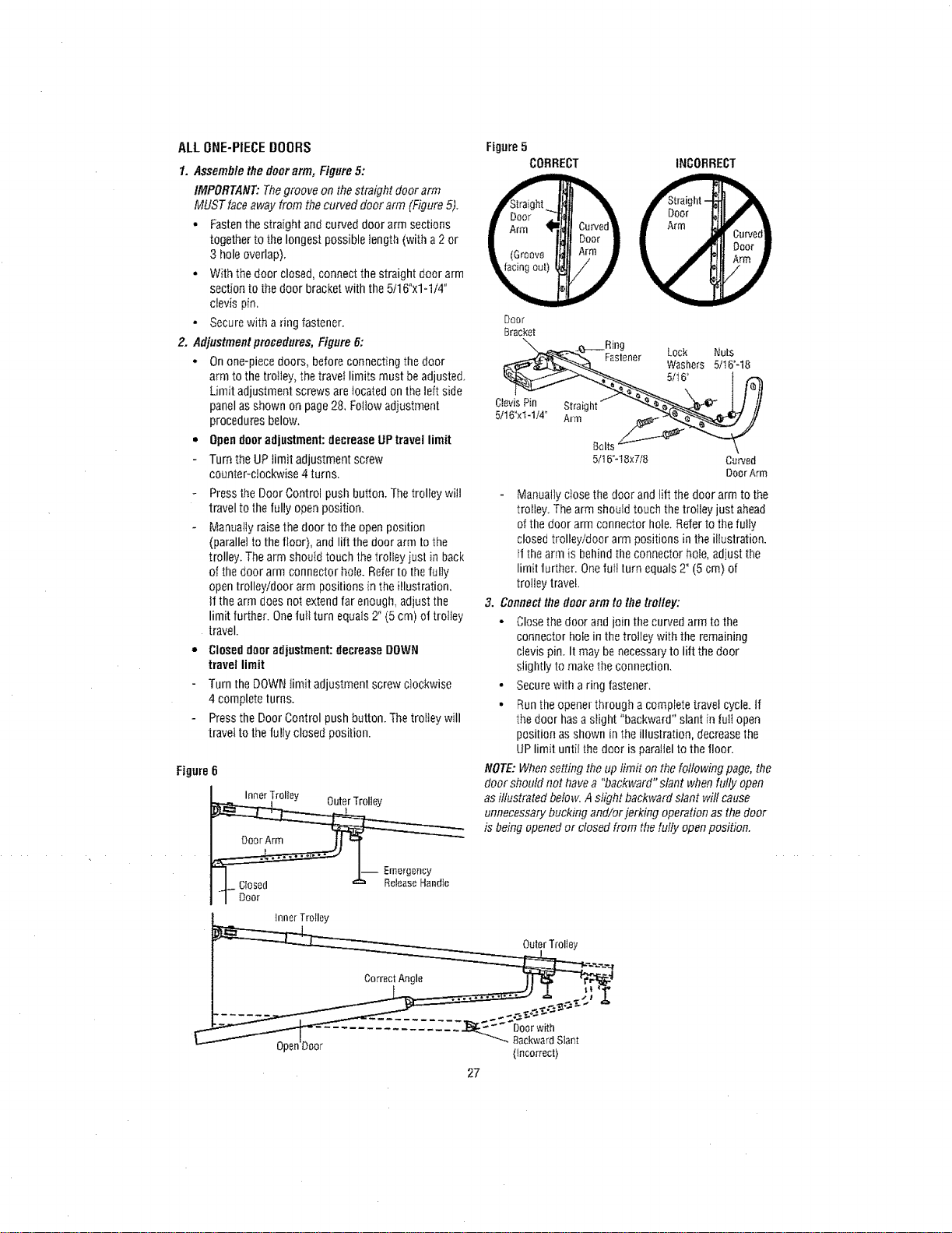
ALLONE-PIECEBOORS
1. Assemblethe door arm, Figure5:
IMPORTANT: Thegroove on thestraight door arm
MUST faceaway from thecurved door arm (Figure 5).
o Fastenthe straight and curved door arm sections
together to the longest possible length (with a2 or
3 hole overlap).
o With the door closed, connect the straight door arm
section to the door bracket with the 5116°xl-1/4"
clevis pin,
• Secure with a ring fastener.
2. Adjustmentprocedures, Figure 6:
• On one-piece doors, before connecting thedoor
arm to the trolley, the travel limits must beadjuste&
Limit adjustment screws are locatedon the left side
panel as shown on page28, Follow adjustment
procedures below.
• Opendoor adjustment: decrease UPtravel limit
Turn theUP limit adjustment screw
counter-clockwise 4 turns.
Figure5
CORRECT
Ctevis Pin Stra[g
5/16"xt-1/4" Arm
Fastener
Bolt
5/16"-t 8x7/8
INCORRECT
Lock Nuts
Washers 5/16"-18
5tt 6"
Curved
Door Arm
Press the Door Control push button. The trolley wiit
travel to thefully openposition,
Manually raisethe door to the open position
(parallet to the floor), andIitt the door arm to the
trolley. The arm shoutd touch the trolley iusl in back
of the door arm connector hole. Refer to the fully
opentrolley/door arm positions in the illustration,
it the arm does not extend far enough, adjust the
limit further. Onefull turn equals 2" (5 cm) of trolley
travel.
ClOseddoor adjustment: decrease DOWN
travel limit
Turn the DOWN limit adjustment screw clockwise
4complete turns.
Pressthe Door Control push button. Thetrolley will
travel to the fully closed position.
Figure 6
I-- Emerge.By
Manually close the door andliit the door arm to the
trolley. Thearm should touch the trolley just ahead
of the door arm connector hole. Referto the fully
closed trolley/door arm positions in the illustration.
If thearm is behind tile connector hole, adjust the
Iim[t turther. Onefurl turn equals 2" (5 cm) of
trolley travel.
3. Connectthe door arm to the trolley:
o Closethe door and join the curved arm tothe
connector hole in the trotley with the remaining
clevis pin. It may benecessaryto lift the door
slightly to make the connection.
• Secure with a ring fastener,
• Runthe openerthrough a complete travel cycle, if
the door hasa slight "backward" slant in lull open
position as shown in the illustration, decreasethe
UPlimit until the door is paraflelto the floor.
NOTE:Whensetting the up limit on thefollowing page, the
door should not havea "backward" slant whenfully open
asillustrated below. Aslight backward slant will cause
unnecessarybucking and/or jerking operation as the door
is being opened or closed from thefully openposition.
innerTroIley
OuterTrolley
Correc!Angle __
........ _-_-_-_"_'__-
-onDoor BackwardSlant
P (Incorrect)
27
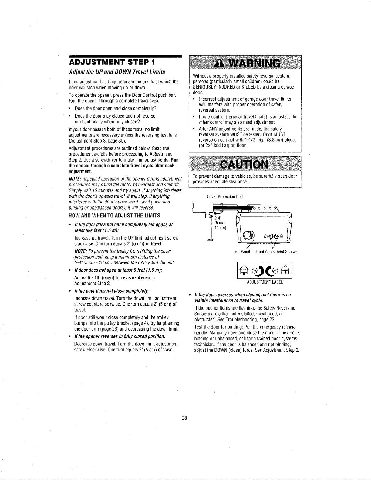
ADJUSTMENT STEP 1
AdjusttheUPandDOWN TravelLimits
Limit adiustment settings regulate the points atwhich the
door wilt stop when moving up or down.
To operate theopener, press the Door Control push bar.
Run the openerthrough a complete travet cycle.
. Does the door open and close completely?
o Does the door stay closed and not reverse
unintentionally when fully closed?
it your door passes both of these tests, no limit
adjustments arenecessary unfessthe reversing test fails
(Adjustment Step 3, page 30).
Adjustment procedures are outlined below. Readthe
procedures carefully before proceeding to Adjustment
Step 2. Use ascrewdriver to make limit adjustments, Bun
the opener through acomplete travel cycle after each
adjustment.
NOTE:Repeatedoperation of the opener during adjustment
procedures may causethe motor to overheat and shut off.
Simply wait !5 minutes and try again, If anything interferes
with the door's upward travel, it wilt stop. If anything
interferes with the door's downward travel (including
binding or unbalanced doors), it win reverse.
HOW AND WHEN TO ADJUST THE LIMITS
• If the doordoesnot opencompletelybutopens at
least live feet (1.5 m):
increase up travel. Turn the UPfimit adjustment screw
clockwise. Oneturn equals 2" (5 cm) of travel.
NOTE: Toprevent the trolley from hitting thecover
protection bolt, keep a minimum distance of
2-4" (5 cm - 10cm) between the trolley and the bolt.
• If door doesnotopenat least 5 feet (1.5 m):
Adjust the UP(open) force as explained in
Adjustment Step 2.
• If the door doesnotclose completely:
Increasedown travel Turn the down limit adjustment
screw counterclockwise. One turn equals 2" (5 cm) of
travel.
If door still won't close completely and the trolley
bumps into the puiley bracket (page 4), try lengthening
the door arm (page 26) and decreasing the down limit,
o If the openerreverses in fully closedposition:
Decreasedown travel. Turn the down limit adjustment
screw clockwise. Oneturn equats 2" (5 cm) of travel.
Without a properly installed safety reversal system,
persons (particularly smali children) could be
SERIOUSLYiNJUREDor KILLED bya closing garage
door.
• Incorrect adjustment of garagedoor travel limits
will interfere with proper operation ol safety
reversalsystem,
• If onecontrol (force or travel limits) is adiusted, the
other control may also needadjustment.
• After ANY adjustments are made, the safety
reversalsystem MUST betested. Door MUST
reverseon contact with "_-1t2"high (3.8 cm) obiect
(or 2x4 laid fiat) on floor.
To prevent damageto vehicles, besure fully open door
provides adequate clearance.
CoverProlectionBolt
JL
'l lllllIH1,
11ocm) H
LeftPanel LimitAdiustmentScrews
ADJUSTMENTLABEL
It the doorreverses whenclosingand there is no
visibleinterference totravelcycle:
if the opener lights are flashing, the SafetyReversing
Sensors are eithernot installed, misaligned, or
obstructed. SeeTroubleshooting, page 23.
Testthe door for binding: Putt the emergency retease
handle. Manually open and close the door. If the door is
binding or unbalanced, call for a trained door systems
technician. It the door is balanced and not binding,
adiust the DOWN(close) force. SeeAdjustment Step 2.
28
ADJUSTMENT STEP 2
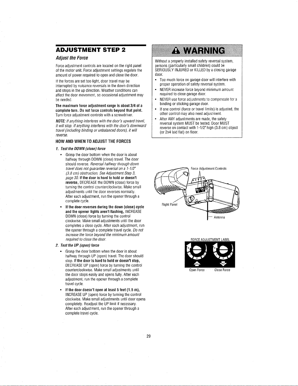
AdjusttheForce
Forceadiustment controls are located on the right panel
of the motor unit. Forceadjustment settings regulate the
amount of power required to openand close the door.
!t the forces are set too light, door travel may be
interrupted by nuisance reversals in the down direction
andstops in the up direction. Weather conditions can
affect thedoor movement, so occasional adjustment may
be needed.
The maximum forceadjustment range is about3/4 of a
completeturn.Do notforce controlsbeyondthat point.
Turn force adjustment controls with a screwdriver.
NOTE:If anything interferes with thedoor's upward travel,
it will stop. tf anything interferes with the door's downward
travel (including binding or unbalanced doors), it will
reverse,
HOW AND WHEN TO ADJUST THE FORCES
1. Test the DOWN(close) for¢e
, Grasp the door bottom when the door is about
halfway through DOWN (close) travel. The door
should reverse, Reversal halfway through down
travel does not guarantee reversal on a 1-!/2"
(3.8 cm) obstruction. SeeAdjustment Step 3,
page30. Ifthe door is hard tohold ordoesn't
reverse, DECREASEthe DOWN (c_ose)force by
turning thecontrol counterclockwise, MakesmaII
adjustments until the door reverses normally.
After each adjustment, runthe opener through a
complete cycle.
• If the doorreversesduring the down (close) cycle
and the opener lights aren't flashing, iNCREASE
DOWN(close) force by turning the control
clockwise. Makesmall adjustments until the door
compEetesa close cycle. After each adiustment, run
the openerthrough a complete travel cycle. Do not
increase the torce beyond theminimum amount
required to close the door.
2. Testthe UP (open) force
- Graspthe door bottom when the door is about
halfway through UP (open) travel. The door should
stop. if the door is hardto holdor doesn'tstop,
DECREASEUP (open) force by turning the control
counterclockwise. Makesmall adiustments until
the door stops easilyand opens fully. After each
adjustment, run the openerthrough acomplete
travel cycle.
• If the door doesn't open at least5 feet (1.5 m),
INCREASEUP(open) force by turning the control
clockwise. Makesmall adjustments until door opens
completely. Readjustthe UP limit if necessary.
After eachadjustment, run the opener through a
complete travei cycle.
Without a properly installed safetyreversal system,
perso_ts(particularIy small children) could be
SERIOUSLYiNJUREDor KILLED by actosing garage
door.
* Too much force ongarage door will interfere with
proper operation ofsafety reversal system.
- NEVERincreaseforce beyond minimum amount
requiredto close garagedoor.
* NEVERuse force adiustments to compensate for a
binding or sticking garage door.
. If one control (force or travel limits) is adjusted, the
other control may also needadiustment.
o After ANY adjustments are made, the safety
reversalsystem MUST betested. Door MUST
reverse oncontact with t-1/2" high (3.8 cm) object
(or 2x4 laid fiat) on floor.
Force Adjustment Conlrols
Right Panel
Antenna
FORCEADJUSTMENT LABEL
29
OpenForce CloseForce
ADJUSTMENT STEP 3
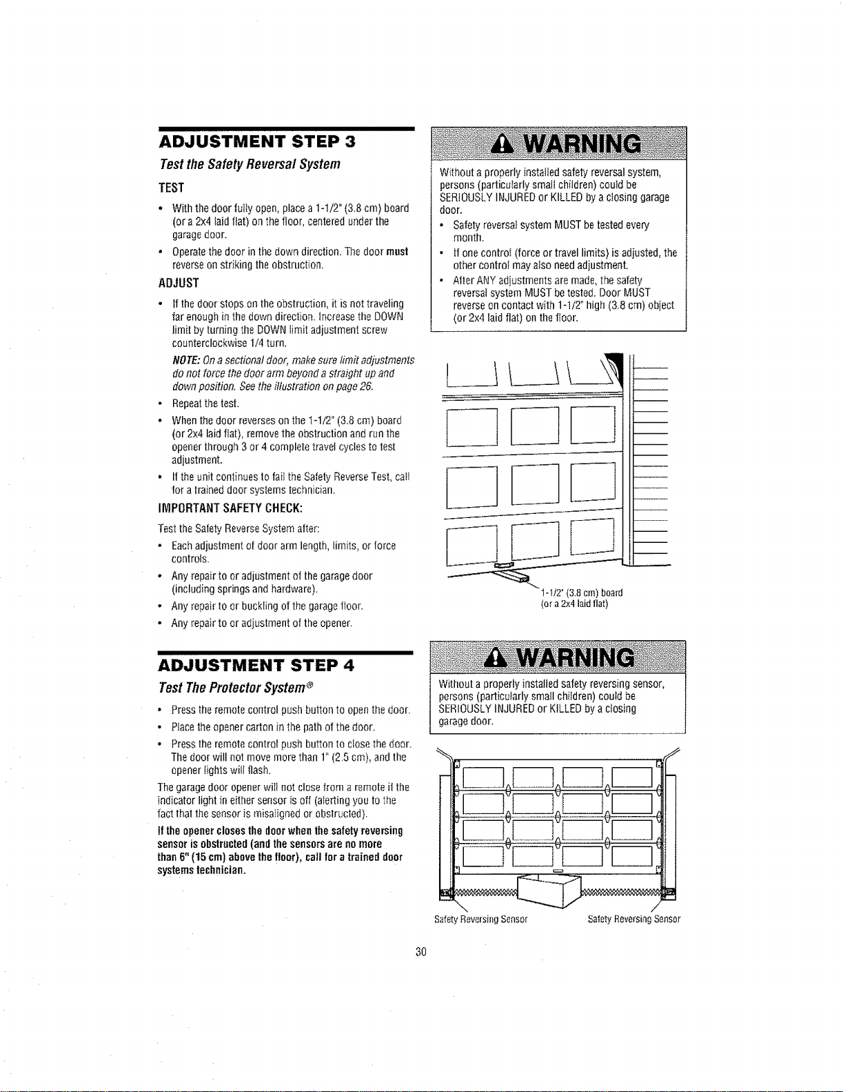
TesttheSafetyReversa/System
TEST
• With the door fully open, placea 1-1/2" (3.8 cm) board
(or a2x4 taid flat) on the floor, centered under the
garagedoor.
• Operatethedoor in the down direction, The door must
reverse onstriking the obstruction.
ADJUST
• tf the door stops onthe obstruction, it is nottraveling
far enough in the down direction. Increasethe DOWN
limit by turning the DOWNlimit adjustment screw
counterclockwise 1/4 turn,
NOTE:Ona sectional door, make sure limit adjustments
donot force the door arm beyonda straight up and
down position. See theillustration onpage26.
- Repeatthe test.
• When the door reverseson the I-1/2" (3.8 cm) board
(or 2x4 laid fiat), remove the obstruction andrun the
opener through 3or 4 complete travel cycles to test
adjustment.
• If theunit continues to fait the Safety ReverseTest,calf
for a traineddoor systems technician.
IMPORTANT SAFETY CHECK:
Testthe Safety ReverseSystem after:
• Eachadjustment of door arm length, limits, or force
controls.
• Any repair to or adjustment of the garagedoor
(including springs and hardware).
• Any repair to or buckling of thegaragefloor.
• Any repair to or adiustment of the opener.
Without a properly installed safety reversal system,
persons (particularly small children) could be
SERIOUSLYINJUREDor KILLED by aclosing garage
door.
• Safetyreversal system MUSTbetested every
month.
• If onecontroi (force or travel limits) is adjusted, the
other controt may also needadjustment,
• Alter ANY adjustments are made, the safety
reversalsystem MUST betested, Door MUST
reverseon contact with 1-1/2" high (3.8 cm) object
(or 2x4 laid flat) on thefloor.
1-1/2°(3.8cm)board
(ora2x4laidflat)
ADJUSTMENT STEP 4
TestTheProtectorSystem®
• Press theremote control push button to open the door.
• Placethe opener carton in the pathof the door,
• Press theremote controI push button to close the door.
Thedoor will not move more than 1" (2,5 cm), and the
openeriights witl flash.
Thegaragedoor opener will not close from a remote it the
indicator light in eithersensor is off (aIertingyou to the
fact that the sensor is misaIigned or obstructed).
!f the opener closesthe doorwhen the safety reversing
sensorisobstructed (and the sensorsare no more
than 6"(15 cm) above the floor), call for a trained door
systemstechnician.
Without a properly installedsafety reversing sensor,
persons (particuiarly small children) could be
SERIOUSLYINJUREDor KILLED by a closing
garagedoor.
Safety Reversing Sensor
CZ3
SafetyReversingSensor
3O

IMPORTANTSAFETYINSTRUCTIONS
ToreducetheriskofSEVEREINJURYor DEATH:
1, READAND FOLLOWALL WARNINGS
AND INSTRUCTIONS,
2. ALWAYS keepremote controls out of reach of
children. NEVERpermit children to operateor play
with garage door control push buttons or remote
controls.
3. ONLYactivate garagedoor when it can be seen
clearly, it is properly adjusted, andthere are no
obstructions to door travel.
4. ALWAYSkeep garagedoor in sight untit completely
closed. NOONESHOULDCROSSTHEPATHOFTHE
MOVING DOOR.
5. NO ONESHOULDGOUNDERA STOPPED,
PARTIALLYOPENDOOR.
6. If possible, useemergency releasehandleto
disengagetroitey ONLYwhen garage door is
CLOSED.Weak or broken springs or unbalanced door
could resuttin an open door failing rapidly and/or
unexpectedly, causing SEVEREINJURY or DEATH.
7. NEVERuse emergency releasehandle unless garage
doorway is clear of persons andobstructions.
8. NEVERuse handle to pull garagedoor open or closed.
!1ropeknot becomes untied, you could fail.
9. if one control (force or travel limits) is adjusted, the
other control may also need adjustment.
10. After ANY adjustments are made,the safety reversal
system MUSTbe tested.
1t. Safety reversal system MUST betested every month.
Garagedoor MUST reverse on contactwith 1-1/2"
(3.8 cm) high object (or a 2x4 laid flat) on the floor.
Failure to adjust the garagedoor opener properly
may cause SEVEREINJURYor DEATH.
12. ALWAYS KEEPGARAGEDOORPROPERLY
BALANCED(seepage3). Animproperly balanced
door may NOTreverse when requiredand could
result in SEVEREINJURYor DEATH.
13. ALL repairs to cables, spring assemblies and
other hardware, ALL of which are under EXTREME
tension, MUST bemade by a trained door systems
technician.
14. ALWAYSdisconnect etectric power to garagedoor
opener BEFOREmakingANY repairs or removfng
COVerS.
t5.
SAVETHESE
INSTRUCTIONS.
31
Using YourGarageDoorOpener
Your Security÷® openerand hand-held remote control
havebeenlactory-set to a matching code which changes
with eachuse, randomly accessing over 100 billion
newcodes. Your openerwill operate with up to eight
Security÷ ®remotecontrols andone Security+ ® Keyless
Entry System. If you purchase a new remote, or if you
wish to deactivateany remote, follow the instructions in
the Programming section.
Activateyour opener withany ofthe following:
• TheHand-Held Remote Control; HeRdthe large push
button down untit the door starts to move.
o TheWall-Mounted Door Control."Hold thepush button
or bardown until the door starts to move.
• TheKeylessEntfv (seeAccessories): If provided with
your garagedoor opener, it must be programmed
before use. See Programming.
Whenthe opener is activated (with the safetyreversing
sensor correctlyinstalled and aligned):
t. If open, thedoor will cfose. It dosed, it will open.
2, If closing, the door will reverse.
3. If opening, the door will stop.
4. If the door has beenstopped in apartially open
position, it will close,
5. It obstructed while closing, the door witi reverse. Ifthe
obstruction interrupts the sensor beam,the opener
lights will blink for five seconds.
6. if obstructed while opening, the door will stop.
7. If fully open, the door will not close when the beamis
broken. Thesensor has no eitect in the opening cycle.
if the sensor is not installed, or is misaligned, the door
won't close from a hand-held remote. However,you can
close the door with the door control the Outside Keylock,
or KeylessEntry, if you activate them until down travel
is complete. If you release them [oo soon, the door will
reverse,
Theopenerlights will turn on under the following
conditions: when the opener is initially plugged in; when
power is restoredafter interruption; whenthe opener is
activated.
Theywitl turn off automatically niter 4-!/2 minutes or
provide constant light when the Light featureon the
Multi-Function Door Control is activated, Bulb size is A19,
Bulb power is 100watts maximum.
Security.i,_ light feature: Lights witl also turn on when
someonewalks through the open garagedoor. With a
Multi-Function Door Control, this feature may be turned off
asfollows: With the opener lights off, press and hold the
fight button for 40seconds, untit the tight goes on, then off
again. To restore this feature, start with the opener lights
on,then press and hold the light button for t0 seconds
until the light goes off, then on again.
32
Usingthe Wa_Mounted DoorControl
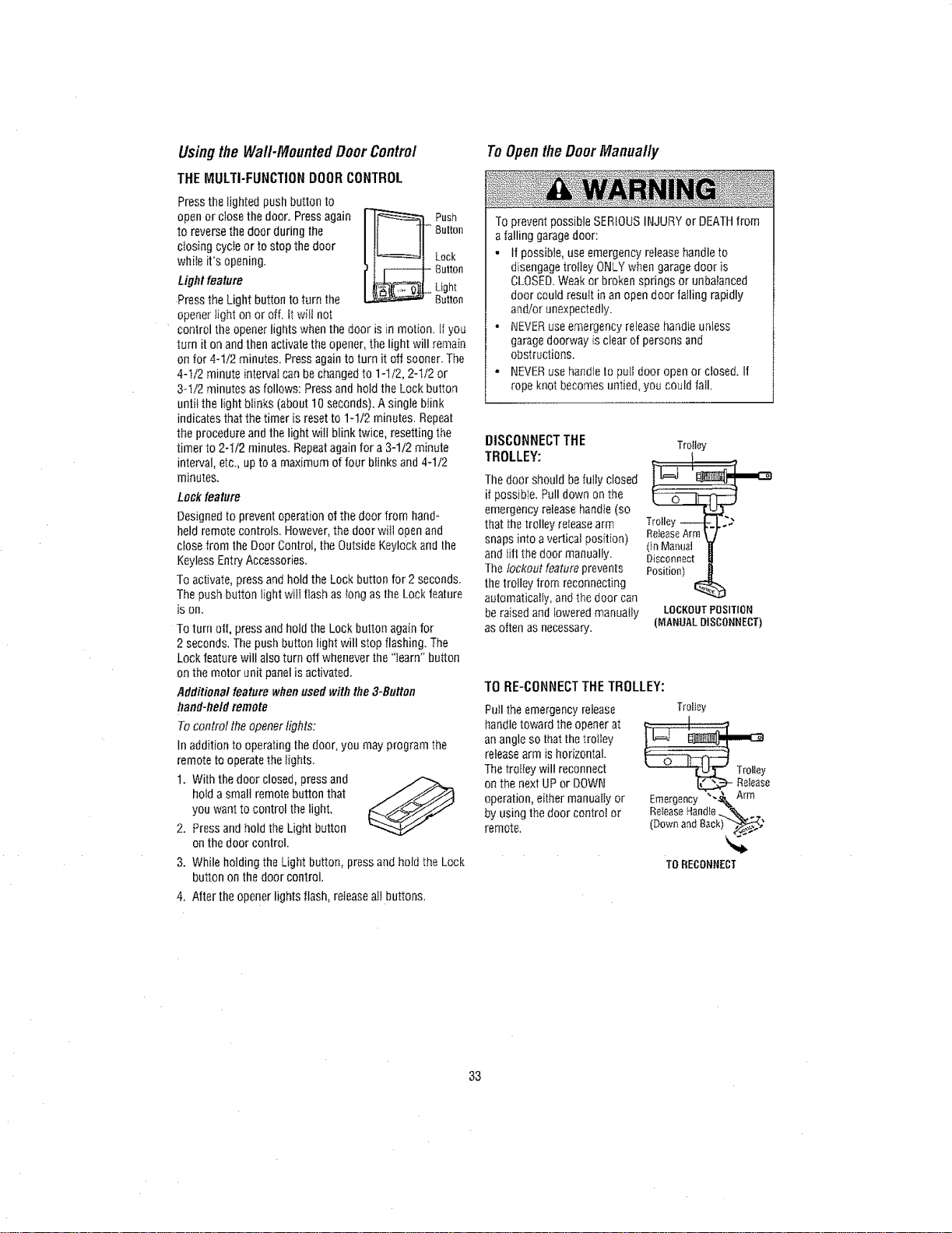
THE MULTI-FUNCTIONDOORCONTROL
Pressthe lighted push button to
openor close the door. Pressagain
to reverse the door during the
cIosing cycte or to stop the door
while it's opening.
Lightfeature
Press the Light button to turn the
openerlight on or off. it will not
Push
Button
Lock
Button
Light
Button
control the openerlights when the door is in motion, if you
turn it on and then activatethe opener, the light will remain
on ior 4-1/2 minutes. Pressagain to turn it off sooner. The
4-1/2 minute interval can be changedto 1-1/2, 2-112or
3q/2 minutes as follows: Press and hold the Lockbutton
untii the light blinks (about 10 seconds). A single blink
indicatesthat the timer is reset to 1-1/2 minutes. Repeat
the procedureandthe light wi!l blink twice, resetting the
timer to 2-t/2 minutes. Repeatagain for a 3-1/2 minute
interval, etc., up to a maximum of four blinks and4-1/2
minutes.
Lock feature
Designed to prevent operation of the door from hand*
held remote controls. However, the door will open and
close from the Door Control, the Outside Keylock andthe
Keyless Entry Accessories.
To activate, press and hold the Lock button for 2 seconds.
The push button light will flash as long as the Lock feature
is on_
To turn otL press andhold the Lock button again for
2 seconds. The push button light will stop flashing. The
Lock feature will alsoturn off whenever the "iearn" button
on the motor unit panel is activated.
Additional feature whenused withthe 3-Button
hand-heN remote
To control the openerlights:
Inaddition to operating the door, you may program the
remote to operatethe Iights.
1. With the door closed, press and .._
hold asmall remotebutton that
you want to control the light.
2. Press andhold the Light button
on the door control.
3. While hotding the Light button, press andhold the Lock
button onthe door control.
4. After the opener lights flash, reieaseall buttons.
ToOpentheDoorManually
To prevent possible SERIOUSINJURY or DEATHfrom
aialling garagedoor:
• If possible, use emergency releasehandle to
disengagetrolley ONLYwhen garagedoor is
CLOSED.Weak or broken springs or unbalanced
door could resutt in an open door falling rapidly
and/or unexpectedly.
• NEVERuseemergency release handteunless
garagedoorway is clear of persons and
obstructions.
° NEVERuse handleto puI[door open or closed. If
rope knot becomes untied, you could fall.
DISCONNECTTHE
TROLLEY:
Thedoor should befully closed
if possible, Pull down on the
emergency releasehandfe(so
that thetrolley refeasearm
snaps into a vertical position)
and lift the door manually.
The lOckOutfeatureprevents
the trolley from reconnecting
automatically, and thedoor can
be raised andioweredmanually
as often as necessary.
Trolley
ReleaseArm\ /
(tnMannai H
Disconnect
Position)
LOCKOUTPOSITION
(MANUALDISCONNECT)
TO RE-CONNECTTHETROLLEY:
Pull theemergency reiease
handle toward the openerat
anangle so thatthe troIIey
releasearm is horizontal.
Thetro[Iey will reconnect
on the nexl UPor DOWN
operation, either manually or
by usingthe door control or
remote.
TrolJey
e
Emergency __
ReieaseHandle '_
(Downand8ack)_'
TO RECONNECT
33
Care ofYourOpener
LIMIT ANDFORCEADJUSTMENTS:
Weather conditions may causesome minor changes in
door operation requiring some re-adiustments, particularly
during the first year of operation.
Pages28 and 29 refer to the limit and force adjustments.
Only a screwdriver is required. FOllOwthe instructions
carefufly.
Repeat the safetyreverse test (AdjustmentStep3,
page 30) alter any adjustmentof limits or force.
FORCECONTROLS
LIMITCONTROLS
[V]AINTENANCE SCHEDULE
Every Month
• Manually operatedoor. if it is unbalanced or binding,
calIa trained door systems technician.
• Checkto be sure door opens andcloses fully, Adjust
limits and/or force it necessary(seepages 28 and 29).
- Repeattile safety reversetest. Makeany necessary
adjustments (seeAdjustment Step 3).
Every Year
• Oil door rollers, bearings andhinges. The opener does
not requireadditional lubrication. Do not grease the
door tracks.
THE REMOTECONTROLBATTERY
To prevent possible SERIOUS INJURYor DEATH:
• NEVERallow small children near batteries.
• tf battery is swallowed, immediately notify doctor.
To reduce risk of fire, explosion or chemical burn:
• ReplaceONLYwith 3V2032 coin batteries.
• DONOTrecharge,disassemble, heatabove 100° C
(212° F) or incinerate.
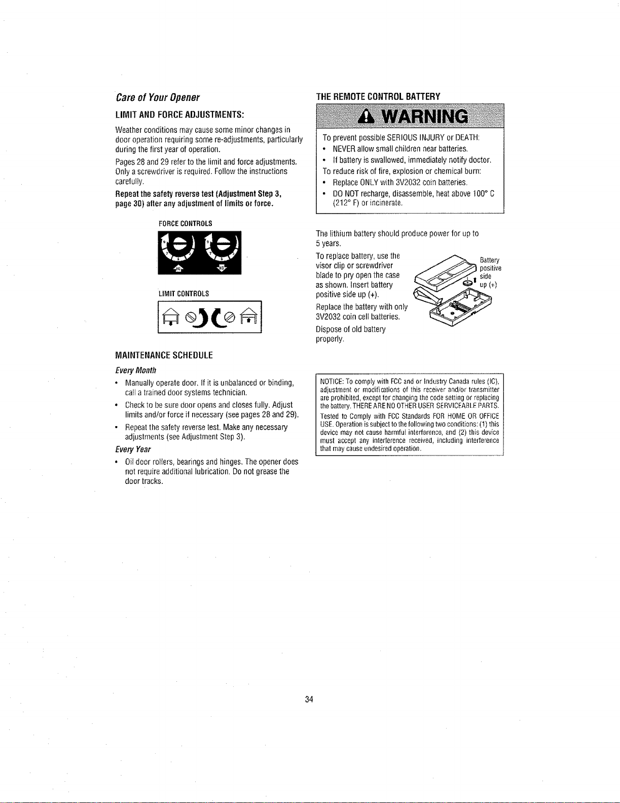
The lithium battery should produce power for upto
5 years.
To replace battery, usethe _ Battery
visor clip or screwdriver _j,,,__ positiveblade to pryopen the case side
as shown, insert battery _,],,,._j_ _" up(+)
positive side up (+),
Replacethe battery with only
3V2032 coin cell batteries.
Dispose of old battery
properly.
NOTICE:To compty with FCCandor Industry Canada rules (It),
adinstment or modifications of this receiver and/or transmitter
are proh{bited, except for changing the code setting or replacing
thebattery. THEREARE NOOTHERUSERSERVICEA£LEPARTS.
Tested to Comply with FCCStandards FOR HOME OR OFFICE
USE.Operation is subjectto thefollowingtwo conditions: (t) this
device may not cause harmful interference,and (2) th{s device
must accept any intederenee received, including interference
that may cause undesired operation
34
Havinga Problem?(Troubleshooting)
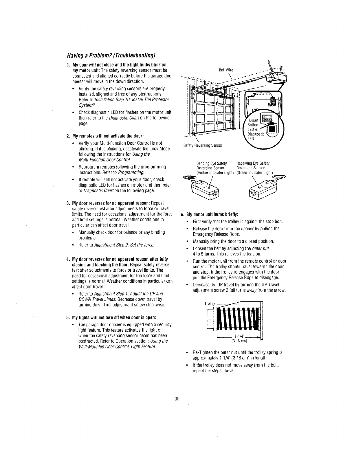
1, My doorwill notcloseand the light bulbs blink on
my motor unit: Thesafety reversing sensor must be
connected andaligned correctly before the garagedoor
openerwill move in the down direction,
• Verify the safetyreversing sensors are properly
installed, aligned andfree of any obstructions.
Referto Installation Step 10:Install TheProtector
SysterrP.
• Checkdiagnostic LEDfor flashes onthe motor unit
thenrefer to the Diagnostic Chart on thefoflowing
page.
2. My remoteswill not activatethe door:
• Verify your Multi-Function Door Control is not
blinking. If it is blinking, deactivate the Lock Mode
following the instructions for Using the
Multi-Function Door Control
- Reprogram remotes following the programming
instructions. Referto Programming.
• If remote wiit stilt notactivate your door, check
diagnostic LEDfor flashes on motor unit then refer
to Diagnostic Chart onthe following page.
3. My dour reversesfor noapparent reason: Repeat
safety reverse test after adjustments to force or travel
limits+The needfor occasional adjustment for the force
and limit settings is normal, Weather conditions in
particular can affect door travel.
• Manuallycheck door for balanceor any binding
problems.
• Referto Adjustment Step 2, Set the force.
4. My doorreverses for no apparent reasonafter fully
closing andtouchingthe llonr: Repeat safety reverse
test after adjustments to force or travel limits. The
needfor occasional adjustment for the force and limit
settings is normal. Weather conditions in particular can
affect door travel.
• Refer to Adjustment Step 1,Adjust the UPand
DOWNTravelLimits, Decreasedown travetby
turning down limit adjustment screw clockwise.
5. My lights will notturn offwhendoor is open:
• The garagedoor opener is equipped with a security
light feature.This feature activates the light on
when the safetyreversing sensor beam has been
obstructed. Relerto Operationsection; Using the
Wall-Mounted Door Control, Light Feature.
BellWire
SafetyReversing Sensor
Sending EyeSafety Receiving EyeSafety
Reversing Sensor Reversing Sensor
(Amber indicator L{ght) (Green Indicator Light)
6. My motor unithums briefly:
• First verify that the trolley is against thestop bolt,
• Releasethe door from the opener by putting the
Emergency ReleaseRope.
• Manually bring the door to aclosed position.
• Loosenthe belt byadjusting the outer nut
4 to 5 turns. This refievesthe tension.
• Runthe motor unit from the remote controt or door
control The trolley should travel towards1hedoor
and stop, If the trolley re-engages with the door,
pull the Emergency ReleaseRopeto disengage.
• Decreasethe UPtravel by turning the UPTravet
adjustment screw 2 full turns awayfrom the arrow.
• Re-Tightenthe outer nut until thetrolley spring is
approximately 1-t/4" (3.18 cm) in length.
• If thetrolley does not move away from the bolt,
repeat the stepsabove.
35
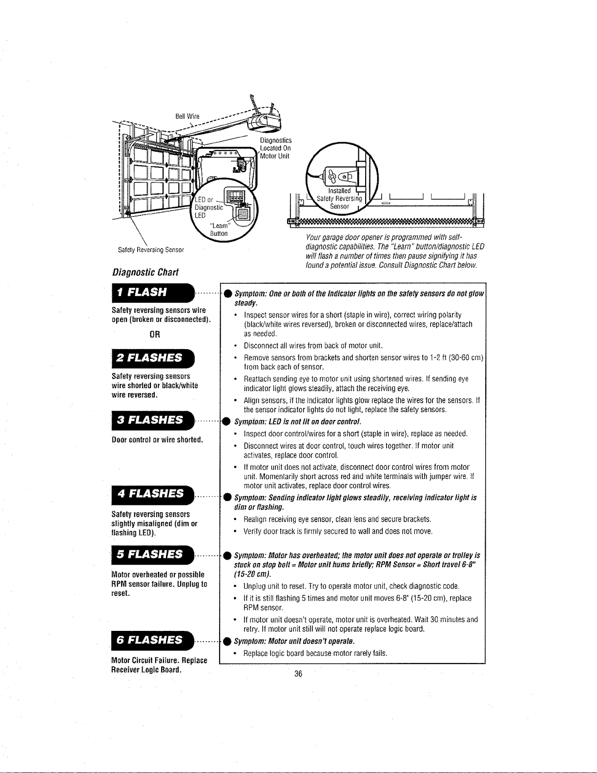
DiagnosticChart
Safetyreversingsensorswire
open(brokenordisconnected).
OR
Safety reversingsensors
wire shortedorblack/white
wire reversed.
Doorcontrolor wireshorted.
Safetyreversing sensors
slightly misaligned (dim or
flashingLED).
Motoroverheatedor possible
RPMsensorfailure. Unplugto
reset.
Motor CircuitFailure. Replace
ReceiverLogicBoard.
Diagnostics
Located On
•Motor Unit
Your garagedoor openeris programmed with self-
diagnostic capabilities. The "Learn" button/diagnostic LED
will flash a number of times thenpause signifying it bas
found a potential issue. Consult Diagnostic Chart below.
•• Symptom:One orboth of the Indicator lightson the safety sensors do notglow
steady.
• Inspect sensor wires for ashort (staple in wire), correct wiring potarity
(black!white wires reversed), broken or disconnected wires, replace/attach
as needed.
• Disconnect ail wires from backof motor unit.
• Removesensors from brackets andshorten sensor wires to 1-2 ft (30-60 cm)
from backeach of sensor.
• ReattachSendingeyeto motor unit using shortened wires. If sending eye
indicator fight glows steadily,attach thereceiving eye.
• Align sensors, if the indicator lights glow replacethe wires for the sensors, tf
the sensor indicator lights do not light, reptace the safety sensors.
Symptom:LEDisnotlit on doorcontrol,
• Inspect door controilwires for a short (staple in wire), replace as needed.
• Disconnect wires atdoor control, touch wires together, if motor unit
activates, replace door control,
• If motor unit does not activate, disconnect door control wiresfrom motor
unit. Momentarily short across red and white terminals with jumper wire. If
motor unit activates, replace door control wires.
Symptom:Sendingindicator lightglows steadily, receiving indicator light is
dim or flashing.
• Realign receiving eye sensor, clean tensand secure brackets.
• Verity door track is firmly secured to wall and does not move.
Symptom:Motor has overheated; the motorunit doesnot operate or trolley is
stuck on stopholt= Motor unithumsbriefly;RPM Sensor= Short travel 6-8"
(15-20 cm).
- UnpIug unit to reset.T_ to operate motor unit, check diagnostic code.
• If it is stilt flashing 5times and motor unit moves 6-8"(15-20 cm), replace
RPM sensor•
• If motor unit doesn't operate,motor unit is overheated. Wait 30 minutes and
retry. If motor unit still will not operate replace logic board,
Symptom:Motor onR doesn't operate.
- Replacelogic board because motor rarely fails.
36
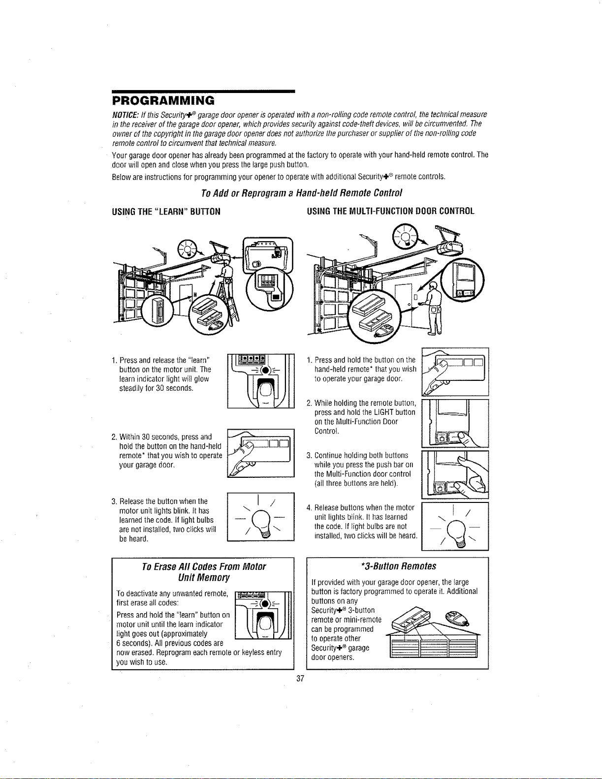
III II IIIIII I IIIIIIIIIIIIII
PROGRAMMING
NOTICE: If this Secufily_ ÷ garage door opener is operated with anomrolfiog code remote control the technical measure
in the receiver of thegarage door opener, whichprovides security against code-theft devices, will becircumvented. The
owner of thecopyright in the garagedoor openerdoes not authorize thepurchaser or supplier of the non-rolling code
remote control to circumvent that technical measure.
Your garagedoor opener has alreadybeen programmed atthe factory to operatewith your hand-held remote control. The
door will openand close when you press the large push button.
Betow are instructions for programming your openerto operatewith additionaI Security÷ ® remote control&
ToAddor Reproflrama Hand-heldRemoteControl
USINGTHE "LEARN" BUTTON
USINGTHEMULTI-FUNCTIONDOORCONTROL
I. Press and releasethe "learn"
button on the motor unit. The
learn indicator light wiil glow
steadily for 30 seconds.
2. Within 30 seconds, press and
hotd the button on the hand-held
remote* that you wish to operate
your garage door.
3. Releasethe button whenthe
motor unit lights blink, it has
learned the code. if light bulbs
are not instaJled,two clicks will
be hear&
\] /
ToEraseAft CodesFromMotor
Unit Memory
To deactivate any unwanted remote,
first erase alt codes:
Press and hoid the "learn" button on
motor unit ontiI the learnindicator
tight goes out (approximately
6 seconds), All previous codesare
now erased. Reprogram each remote or keyless entry
you wish to use.
37
Press and hold the button on the
hand-held remote* thatyou wish
to operate your garagedoor.
While holding the remote button,
press and hold the LIGHTbutton
on the Multi-Function Door
Control
Continue hoJding both buttons
while you press the push bar on
the Multi-Function door control
(all three buttons areheld).
Releasebuttons when the motor
unit lights blink. It has learned
the code. If Iight bulbs are not
installed, two clicks will beheard.
...I /
*3-ButtonRemotes
If provided with your garagedoor opener,the large
button isfactory programmed to operateit. Additional
buttons on any
Security÷ ®3-button
remote or mini-remote
can be programmed
to operateother
Security÷ ®garage
door openers.
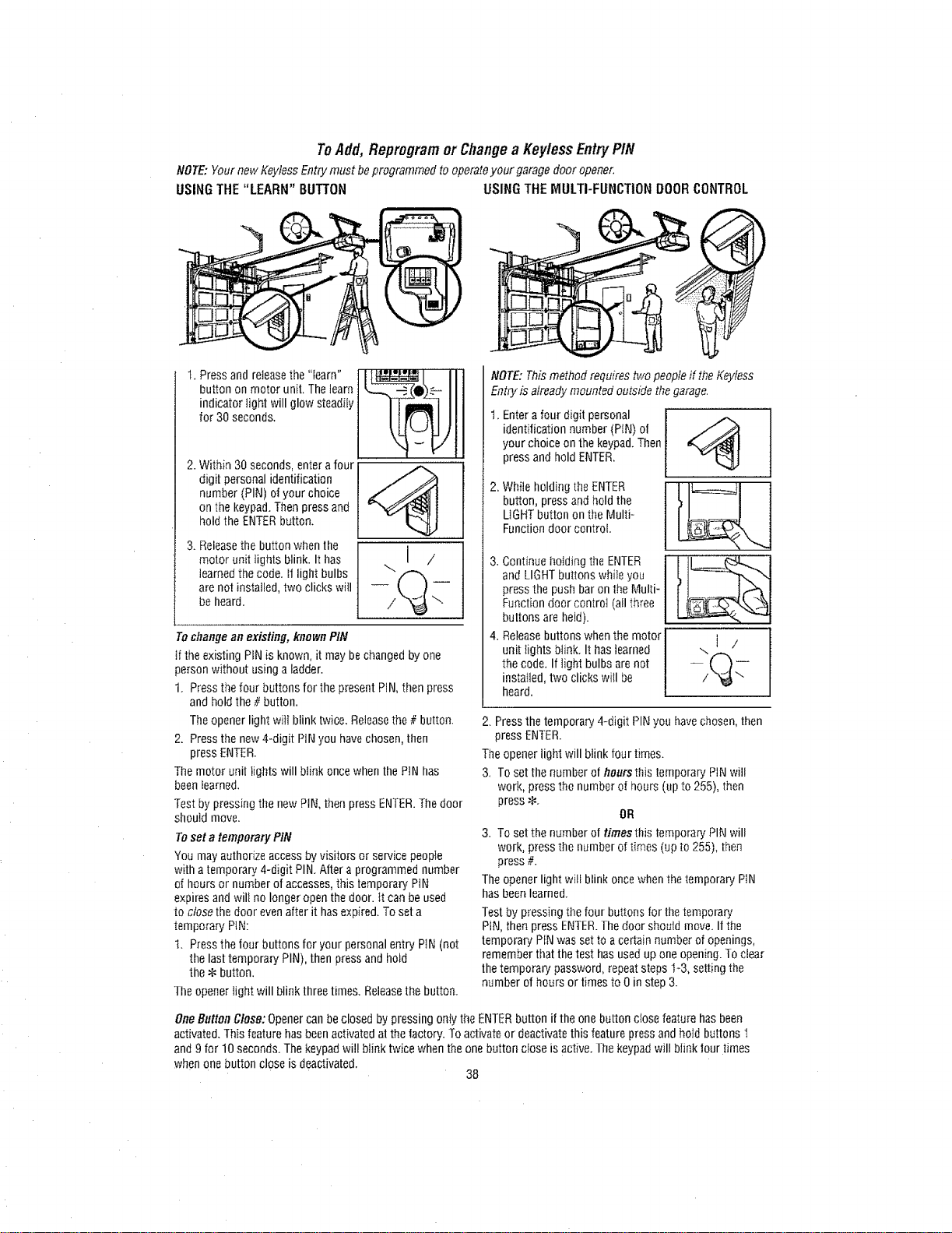
ToAdd,Repmgramor Changea Key/essEntryPIN
NOTE: Yournew KeytessEntry must beprogrammed to operateyour garage door opener,
USING THE "LEARN" BUTTON USING THE MULTI-FUNCTION DOOR CONTROL
t, Pressand releasethe "learn" J_ j .................
button on motor unit, Thelearn LL_._ (0)-'_
indicator fight will glow steadiiy J [T--mRI_ I I I
2. Withfn 30 seconds, entera four
digit personal identification
number (PIN) of your choice
on the keypad.Then press and
hold the ENTERbutton.
3. Releasethe button when the
motor unit lights blink. It has
learned thecode. if light bulbs
are not installed, two clicks will
beheard.
.,.I /
Tochange an existing, known PIN
If the existing PiN is known, it may bechanged by one
person without usinga ladder.
1. Pressthe four buttons for the present PIN,then press
and hold the# button.
The opener light will blink twice, Releasethe # button.
2. Pressthe new4-digit PiN you havechosen, then
press ENTER.
The motor unil lights will biink once when the PIN has
beenlearned.
Test by pressing the newPiN, then press ENTER.The door
sboutd move.
Toset a temporary PIN
You may authorize access by visitors or service people
with a temporary 4-digit PIN. After a programmed number
of hours or number of accesses, this temporary PiN
expires and wilt no longer open the door. it can be used
to close the door evenafter it hasexpired. To set a
temporary PiN:
t. Press the four buttons for your personal entry PIN (not
the last temporary PIN), then press and hold
the .!_button.
The opener tight will blink three times. Releasethe button.
NOTE: Thismethod requires two people it the Keytess
Entry is already mounted outside the garage.
Entera four digit personal
identification number (PIN) of
your choice on the keypad. Then
press and hold ENTER.
2Whehodn theENTER
button, press and hold the
LIGHTbutton on the Multi-
Function door control.
and LIGHTbuttons wtlile you
press the push bar on the Multi-
Function door controt (all three
buttons are held).
4. Release buttons whenthe motor J
unitIights blink. It hasiearned J --. [ /
the code. If light bulbs are not J
2. Pressthe temporary 4-digit PINyou havechosen,then
press ENTER.
The opener light will biink four times.
3. To set the number of floursthis temporary PIN will
work, press the number of hours (up to 255), then
press *.
OR
3. To set the number or times this temporary"PIN will
work, press the number of times (up to 255), then
press #.
The opener light wili blink once whenthe temporary PIN
has been learned.
Testby pressing the four buttons for the temporary
PIN, then press ENTER.The door should move. II the
temporary PIN was set to acertain number of openings,
remember that thetest has used up one opening.To clear
lhe temporary password, repeatsteps I-3, setting the
number of hours or times to Oin step 3.
OneButton Close:Opener can be closed by pressing only the ENTERbutton if the onebutton close feature has been
activated. This featurehas been activatedat the factory. To activate or deactivate this feature press and ho_dbuttons 1
and 9 for 10 seconds. The keypadwill blink twice when theone button ciose is active. The keypadwill blink tour times
when one button close is deactivated,
38
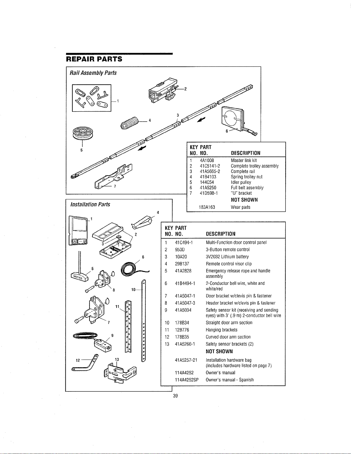
REPAIR PARTS
Rai/ Assemb/yParts
_ KEYPART
tnstal/ationParts
t3
7 41D598-1 "U" bracket
NOT SHOWN
183A163 Wear pads
KEY
NO.
1
2
3
4
5
6
7
8
9
t0
tt
t2
t3
PART
NO,
41C494-I
953D
10A20
29BI37
41A2828
41B4494-1
4tA5047-1
41A5047-3
41A5034
178B34
t2B776
t78B35
41A5266-t
41A5257-21
114A4252
114A4252SP
J
39
DESCRIPTION
Multi-Function door control panel
3-Button remote control
3V2032 Lithium battery
Remote control visor clip
Emergency releaserope and handle
assembly
2-Conductor bell wire, white and
white/red
Doer bracket w/clevis pin & fastener
Header bracket wlclevis pin & fastener
Safety sensor kit (receiving and sending
eyes) with 3' (.9 m) 2-conductor beti wire
Straight door arm section
Hanging brackets
Curved door arm section
Safety sensor brackets (2)
NOT SHOWN
installation hardware bag
(includes hardware listed on page7)
Owner's manual
Owner's manual - Spanish
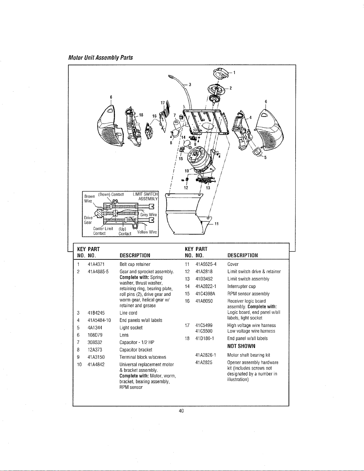
Motor UnitAssemblyParts
Brown (Down)Contact LtMITSWITCH
Wire\_LY
Orive_ re
Gear ---"r-_
Contact Contact YellowWire
t
/ 10_
/'
/ I /
12 t
!
/
6
4\
/
t
/
/
t
!
!
]
KEY PART KEY PART
NO. NO. DESCRIPTION NO. NO. DESCRIPTION
t 4tA4371 Belt cap retainer 11 41A5525-4 Cover
2 41A4885-5 Gearand sprocket assembly. 12 41A2818 Limit switch drive & retainer
Completewith: Spring 13 41D3452 Limit switch assembly
washer, thrust washer,
retaining ring, bearing plate, 14 41A2822-1 Interruptercup
roll pins (2), drive gear and 15 41C4398A RPMsensor assembly
worm gear, helical gearwI 16 41AB050 Receiver logic beard
retainer andgrease assembly. Completewith:
3 41B4245 Line cord Logic hoard, end panet w/eli
4 41A5484-t0 Endpanelsw/all labels labels, light socket
5 4At344 Light socket I7 41C5499 High voltage wire harness
4IC5500 Low voltage wire harness
6 108D79 Lens
18 4ID180-1 End panelwialt labels
7 308532 Capacitor- 1/2 HP
8 12A373 Capacitorbracket NOTSHOWN
9 4IA3150 Terminal block w/screws 4tA2826-1 Motor shall bearing kit
10 41A4842 Universal replacement motor 41A2825 Opener assembly hardware
& bracket assembly, kit (includes screws not
Completewith: Motor, worm, designated by a number in
bracket, bearing assembly, illustration)
RPMsensor
4O
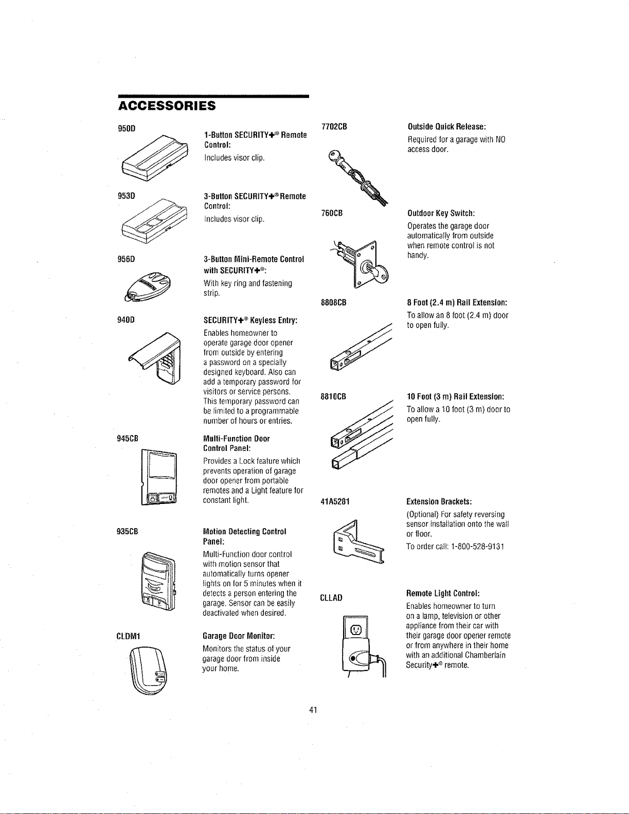
ACCESSORIES
950D
@
953D
956O
940O
945CB
935CB
CLDM1
1-ButtonSECURITY÷®Remote
Control:
Includesvisorclip.
3-ButtonSECURITY÷®Remote
Control:
tnciudesvisorctip.
3-ButtonMini-RemoteControl
withSECURITY÷®:
Withkeyringandfastening
strip.
SECURITY÷®I(eyiessEntry:
Enableshomeowner to
operategaragedoor opener
from outside by entering
apassword ona specialty
designed keyboard.Also can
add atemporary password for
visitors or service persons.
Tllis temporary password can
belimited to a programmable
number of hours or entries.
Multi-Function Door
Control Panel:
Providesa Lock feature which
prevents operation of garage
door openerfrom portabte
remotes and a Light featurefor
constant light.
Motion DetectingControl
Panet:
Multi-Function door control
with motion sensor that
automatically turns opener
lights on for 5 minutes when it
detectsa person entering the
garage.Sensor can be easily
deactivatedwhendesired.
GarageDoor Monitor:
Monitors the status of your
garage door from inside
your home.
7702CB
760CB
%
8808CB
8810CB
41A5281
CLLAD
OutsideQuickRelease:
Required for a garagewith NO
accessdoor.
Outdoor KeySwitch:
Operatesthe garagedoor
automatically lrom outside
whenremote control is not
handy.
8 Font(2.4 m) Rail Extension:
To allow an8 foot (2.4 m) door
to open fuIly.
10 Font (3 m) Rail Extension:
To allow a t0 foot (3 m) door to
openfully.
ExtensionBrackets:
(Optional) Forsafety reversing
sensor installation onto the waft
or iloor.
To order call: 1-800-528-9131
RemoteLightControl:
Enableshomeowner to turn
on a lamp, television or other
appliance from their car with
their garagedoor opener remote
or from anywhere in their home
with an additional Chamberlain
Security÷ ®remote.
41

NOTES
42

43

CHAMBERLAIN®SERVICEIS
ONCALL
OURLARGESERVICEORGANIZATION
SPANSAMERICA
INSTALLATIONAND SERVICEINFORMATIONIS
AS NEARAS YOURTELEPHONE.SIMPLY DIAL
OURTOLLFREENUMBER:
1-800-528-9131
www.chamberlain.com
For professionalinstallation, partsandservice,
contact your local CHAMBERLAIN®dealer. Look for
him in theYeEtowPages,or caif our Service nurnbe_"for
aJist of dealers in your area.
HOWTOORDER
REPAIRPARTS
Selling prices will be furnished on request, or parts
will be shipped at prevailing prices and you wiIl be
billed accordingly.
WHENORDERINGREPAIRPARTS,ALWAYS
GIVETHEFOLLOWINGINFORMATION:
* PARTNUMBER
* PARTNAME
* MODELNUMBER
ADDRESSORDERSTO:
THE CHAMBERLAIN GROUP, INC.
Technical SupportGroup
6050 S. Country Club Road
Tucson, Arizona 85706
SERVICEINFORMATIONTOLLFREENUMBER:
1-800-528-9131
CHAMBERLAIN®ONE-YEARLIMITEDWARRANTY
10 YEARBELTLIMITEDWARRANTY& LIFETIMEMOTORLIMITEDWARRANTY
Tl_eChamberlain Group, inc ("Seller") warrants to the first retail purchaser of this product, for the residence inwhich this product is
origina}ly installed, that it is free from defect in materials and/or workmanship for a period of one year from the dale of purchase, and
that the be_tis free from defect in materials andtor workmanship for a pedod of !0 years from the date of purchase and that the motor
is free from defect in materials and/or workmanship for thelifetimeof theproduct. The proper operation of this product is dependent on
your compliance with theinstructions regarding installation, operation, maintenance and testing. Failureto compty strictly with those
instructions will voidthis Iimited warranty in its entirety.
it, during the limitedwarranty period, this product appears to contain a defect covered by this limited warranty, call 1-800-528-9131,
toil free, before dismantling this product. Then send this product, pro-paid and insured, to our service center for warranty repair. You
will be advised of shipping instructions when you call Please include a brief description of the problem and adated proof-of-purchase
receipt with any product returned for warranty repair. Products fetusned to Seller for warranty repair, which upon receipt by SetIer are
confirmed to be defectiveand covered by this limited warranty, will be repairedor replaced (atSeller's sole option) atno cost to you and
returned pro-paid. Defectiveparts will be repaired or replaced with new or factory-rebuilt paris at Seller's sole option.
ALLIMPLIEDWARRANTIESFORTHEPRODUCT,INCLUDINGBUTNOTUMITEDTOANY IMPLIEDWARRANTIESOFMERCHANTABILITY
AND FITNESS FORA PARTICULARPURPOSE, ARE LIMITED IN DURATIONTO THE ONEYEAR LIMITED WARRANTYPERIOD SET
FORTHABOVE[EXCEPTTHEIMPLIED WARRANTIESWITH RESPECTTOTHE BELTAND MOTOR,WHICHARE LIMITEDiN DURATION
TO THE BELT I0 YEARS AND MOTOR LIFETIME LIMITED WARRANTYPERIOD FOR THE BELTAND MOTOR], AND NO IMPLIED
WARRANTIESWILL EXIST ORAPPLYAFTERSUCHPERIOD. Somestates do not allow limitations onhowlong an imptied warran_
lasts, so theabove ]imitation may netapply to you. THIS LIMITEDWARRANTYDOESNOT COVERNON-DEFECTDAMAGE,DAMAGE
CAUSEDBY IMPROPERINSTALLATION, OPERATIONORCARE(INCLUDING, BUT NOT LIMITED TOABUSE, MISUSE, FAILURETO
PROVIDEREASONABLEAND NECESSARYMAINTENANCE,UNAUTHORIZEDREPAIRSORANY ALTERATIONSTO THIS PRODUCT),
LABORCHARGESFOR REINSTALLINGA REPAIREDOR REPLACED UNIT, REPLACEMENTOF BATTERIESAND LIGHT BULBS OR
UNITSINSTALLED FOR NON-RESIDENTIALUSE.
THIS LIMITED WARRANTYDOESNOT COVERANY PROBLEMSWITH, OR RELATINGTO, THE GARAGEDOOROR GARAGEDOOR
HARDWARE, INCLUDING BUT NOT LIMITED TO THE DOOR SPRINGS, DOOR ROLLERS, DOORALIGNMENT OR HINGES. THiS
LIMITEDWARRANTYALSODOESNOT COVERANYPROBLEMSCAUSEDBYINTERFERENCE.ANYSERVICECALLTHATDETERMINES
THE PROBLEMHAS BEENCAUSEDBYANY OF THESEITEMS COULDRESULTtN A FEETO YOU.
UNDER NO CIRCUMSTANCESSHALL SELLER BE LIABLE FOR CONSEQUENTIAL,INCIDENTAL OR SPECIAL DAMAGESARISING
IN CONNECTIONWITH USE, OR INABIL|TY TO USE, THIS PRODUCT. :INNO EVENTSHALL SELLER'SLIABILITY FORBREACHOF
WARRANTY, BREACHOF CONTRACT,NEGLIGENCEORSTRICT LIABILITY EXCEEDTHECOSTOFTHE PRODUCTCOVEREDHEREBY.
NOPERSONIS AUTHORIZEDTOASSUME FORUS ANY OTHERLIABILITY tN CONNECTIONWITH THESALEOFTHIS PRODUCT.
Some statesdo not allow theexclusion or limitation of consequential, incidental or special damages, so the abovelimitation or exclusion
may not apply to you. This limited warranty gives you specific legal rights, and you may also have other rights which vary from state
tOstate.
I
© 2011, The Chamberlain Group, Into
114A4252B All Rights Reserved

