Loading ...
Loading ...
Loading ...
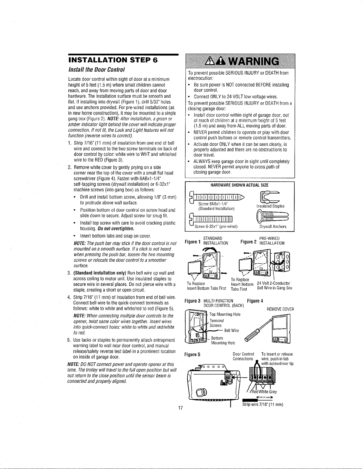
INSTALLATION STEP 6
InstalltheDoorControl
Locate door control within sight of doer at a minimum
height of 5 feet(t.5 m) where smafichildren cannot
reach, and away from moving parts of door and door
hardware. The installation surface must besmooth and
flat. if installing into drywall (Figure 1), drill 5/32" ho_es
and useanchors provided. For pre-wired installations (as
in new homeconstruction), it may bemounted to a single
gangbox (Figure 2). NOTE:After installation, a green or
amber indicator light behind thecover will indicate proper
connection. If not lit, the Lockand Light features will not
function (reverse wires to correct).
1. Strip 7/16" (tl ram) of insulation from one end of bell
wire and connect to the two screw terminals on back of
door control by color: white wire to WriT andwhite/red
wire to the RED(Figure 3).
2. Removewhite cover by gently prying on a side
corner nearthe top of thecover with asmall flat head
screwdriver (Figure 4), Fastenwith 6ABx1-ti4"
self-tapping screws (drywall installation) or 6-32xt"
machine screws (into gang box) as fOllOwS:
- Drill and instatl bottom screw, allowing I/8" (3 mm)
to protrude above wall surface.
• Position bottom ot door controI on screw headand
slide down to secure. Adjust screw for snug fit,
•tnstali top screw with care to avoidcracking plastic
housing. Denot overtighten,
- Insert bottom tabs and snap on cover.
NOTE: Thepush bar may stick if thedoor control is not
mounted on a smooth surface, ira click is not heard
when pressing thepush bar, loosen thetwo mounting
screws or relocate the door control to a smoother
surfacer
3. (Standard installation only) Run bell wire up wattand
across ceiling to motor unit. Use insulated staplesto
secure wire in several places. Donot pierce wire with a
staple,creating a short or opencircuit.
4. Strip 7/16" (11 ram) of insulation from end of bell wire.
Connectbell wire to the quick-connect terminals as
foflows: white to white andwhite/red to red (Figure5),
NOTE:When connecting multiple door controls tothe
opener, twist samecolor wires together. Insed wires
into quick-connect holes: white to white and red/white
to red.
5, Use tacks or staples to permanentfyattach entrapment
warning labelto wall neardoor control, and manuat
release/safetyreverse test labelin a prominent location
on inside of garagedoor,
NOTE: DONOTconnect power and operateopener at this
time. Thetrolley will travel to the full openposition but wilt
not return to the close position until the sensor beamis
connected and properly aligned.
17
To prevent possible SERIOUSINJURYor DEATHfrom
electrocution:
• Besure power is NOTconnected BEFOREinstalling
door control,
• Connect ONLYto 24 VOLTlow vottage wires.
To prevent possible SERIOUSiNJURY or DEATHfrom a
closing garagedoor:
• lnstalt door controI within sight of garage door, out
of reach of children at a minimum height of 5 feet
(1.5 m) and awayfrom ALL moving pads of door.
- NEVERpermit children to operate or play with door
control push buttons or remote control transmitters.
° Activatedoor ONLYwhen it can be seen clearly, is
property adjusted and there are no obstructions to
door travel.
• ALWAYS keepgaragedoor in sight until completely
closed. NEVERpermit anyone to cress path of
closing garagedoor.
HARDWARESHOWNACTUALSIZE
_ liiiiTi_ii_iiiiiliiJliiJ_
Screw6ABxlol/4°
(StandardInstallation)
InsulatedStaples
D_'wallAnchors
STANDARD PRE-WIRED
Figure 1 INSTALLATION Figure 2 _NSTALLATtON
ToReplace InsertBottom 24Volt2-Conductor
insertBottomTabsFirst TabsFirst BellWirein GangBox
Figure 3 MULTI FUNCTION Figure 4
DOORCONTROL(BACK)
REMOVECOVER
TOp Mounting Hole
Terrninat
Beli Wire
g Hole
Figure5
Door Control To insert or release
Connections wire, push in tab
with screwddver tip
:tWhiteGrey
Stripwire7/t6"(11 turn)
Loading ...
Loading ...
Loading ...