Loading ...
Loading ...
Loading ...
iiiiiiiiiiiiiiiiiiiiiiiiiiiiiiiiiiiinln nil i nllnl i
INSTALLATION STEP 12
ConnectDoorArm tothe Trolley
FoItowinstructions which apply to your door type as
illustrated below andon thefollowing page,
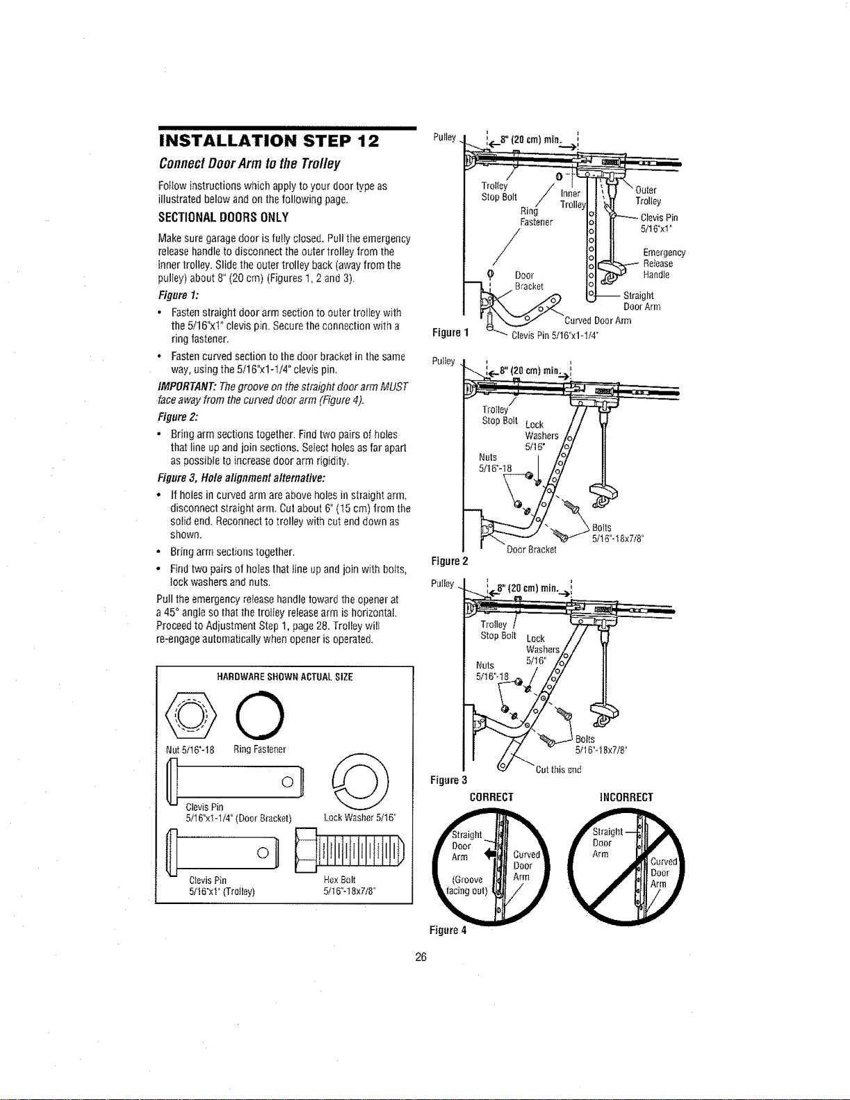
SECTIONAL DOORS ONLY
Make sure garagedoor is fully closed. Pult the emergency
release handleto disconnect theouter trolley from the
inner trolley. Slide the outer trolley back (awayfrom the
pulEey)about 8" (20 cm) (Figures1,2 and 3).
Figure I:
. Fastenstraight door arm section to outer trofleywith
the 5/16"xi" clevis pin. Securethe connection with a
ring fastener.
• Fastencurved section to thedoor bracket in the same Pulley
way, using the 5/16"xl-1/4" clevis pin,
IMPORTANT: Thegroove on thestraight door arm MUST
face away from the curved door arm (Figure 4).
Figure 2:
• Bring arm sections together. Ffnd two pairs of holes
that fine upand join sections. Select holes as far apart
as possible to increase door arm rigidity,
Figure 3, Hole alignment alternative:
• If holes in curved arm are above holes in straight arm,
disconnect straight arm. Cut about 6"(t5 cm) from the
solid end. Reconnect to trolley with cut enddown as
shown.
• Bring arm sections together.
° Find two pairs of holes that line upand join with bolts,
lock washers and nuts. Putiey
Pull the emergencyrelease handletoward the opener at
a 45°angie so that the trotiey releasearm is horizontal.
Proceedto Adjustment Step 1,page28. Trolley will
re-engageautomatically when opener is operated.
HARDWARESHOWNACTUALSIZE
@0
Nut5/t6"-I8 RingFastener
ClevisPin
5/16"xIol/4"(Door8racket) LockWasher5/t6"
CIevisPin HexBolt
5/!6"x1"(Trolley) 5/16_-18x7t8"
om)min.
Trolley/
StopBoit Lock
Washers
5116"
Nuts I
5/16"-18 _J
' DoorBracket
Figure2
Figure
Figure4
Boils
5/16"-18x7/8"
;(..B"(2oor.)mi.._i
sto BottLouk// (
Washers_/ 1
NutS 5/}6" Lo7 I
oo, ?
Cutthis_nd
CORRECT INCORRECT
26
Loading ...
Loading ...
Loading ...