Loading ...
Loading ...
Loading ...
NOTE: If a gas connector is used, it MUST be acceptable to local
authority. Connector MUST NOT be used inside the furnace or be
secured or supported by the furnace or ductwork.
FIRE OR EXPLOSION HAZARD.
Failure to properly install metal gas connector could result
in death, bodily injury and/or property damage.
A flexible corrugated metal gas connector must be
properly installed, shall not extend through the side of the
furnace, and shall not be used inside the furnace.
Black iron pipe shall be installed at the furnace gas control
valve and extend a minimum of 2" outside furnace.
4. Use pipe joint compound on external (male) threads ONLY.
Joint compound MUST be resistant to any chemical action of
LP gases). Do NOT put pipe compound on last 2 threads of
pipe.
5. Use ground joint unions and install a drip leg no less than 3
inches (76 mm) long to trap dirt and moisture before it can en-
ter gas valve.
FIRE HAZARD
Failure to follow safety warnings exactly could result in
serious injury, death, and/or property damage.
Use wrench to hold furnace gas control valve when
turning elbows and gas line to prevent damage to the gas
control valve and furnace.
7. Provide a 1/8 inch (3mm) National Pipe Thread (NPT) plug for
test gauge connection immediately upstream of the gas sup-
ply connection to the furnace if none is supplied with the gas
valve of unit.
8. install a manual shutoff valve and tighten all joints securely.
9. Make sure pi!ot tube and burner orifices are checked for leak-
age.
ORIFICES
Orifice Sizes
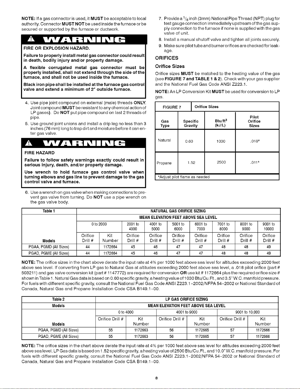
Orifice sizes MUST be matched to the heating value of the gas
(see FIGURE 7 and TABLE 1 & 2). Check with your gas supplier
and the National Fue! Gas Code ANSI Z223.1.
NOTE: An LP Conversion Kit MUST be used for conversion to LP
as.
FIGURE 7 Orifice Sizes
Pilot
Gas Specific Btu/ft s Orifice
Type Gravity (kJ/L) Sizes
Natural 0.60 1030 .018"
Propane 1.52 2500 ,011"
*Adjust pilot flame as needed
6. Use a wrench on gas valve when making connections to pre-
vent gas valve from turning. Do NOT use a pipe wrench on
the gas valve body.
Table1 NATURALGASORIFICESIZING
MEANELEVATIONFEETABOVESEALEVEL
0to 2000 2001to 4001to 5001to 6001to 7001to 8001to 9001to
4000 5000 6000 7000 8000 9000 10000
Orifice Kit Orifice Orifice Orifice Orifice Orifice Orifice Orifice
Models Dril! # Number Drill # Dril! # Dri!l # Dril! # Drill # Drill # Dri!l #
PGAA,PGMD(AllSizes) 44 1172664 45 46 47 47 48 48 49
PGAD,PGME(AllSizes) 44 1172664 45 46 47 47 48 48 49
NOTE: The orifice sizes in the chart above derate the input rate at 4% per 1000 feet above sea level for altitudes exceeding 2000 feet
above sea leve!. If converting from LP gas to Natural Gas at altitudes exceeding 2000 feet above sea level, a .018 pilot orifice (part #
503211 ) and gas valve conversion kit (part # 1147772) are required for conversion OR use kit # 1172664 plus the required orifice size #
shown in Table 1. Natural Gas data is based on 0.60 specific gravity, a heating value of 1030 Btu/Cu. Ft., and 3.5" W.C. manifold pressure.
For fuels with different specific gravity, consult the National Fuel Gas Code ANSI Z223.1-2002/N FPA 54-2002 or National Standard of
Canada, Natural Gas and Propane installation Code CSA B149.1-00.
Table2
Models
Models
PGAA, PGMD (All Sizes)
PGAD, PGME (All Sizes)
LP GAS ORIFICE SIZING
MEAN ELEVATION FEET ABOVE SEA LEVEL
0 to 4000 4001 to 9000 9001 to 10,000
Orifice Drill # Kit Orifice Drill # Kit Orifice Drill # Kit
Number Number Number
55 1172663 56 1172665 57 1172666
55 1172663 56 1172665 57 1172666
NOTE: The orifice sizes in the chart above derate the input rate at 4% per 1000 feet above sea level for altitudes exceeding 2000 feet
above sea level. LP Gas data is based on 1.52 specific gravity, a heating value of 2500 Btu/Cu. Ft., and 10.0" W.C. manifold pressure. For
fuels with different specific gravity, consult the National Fue! Gas Code ANSI Z223.1-2002/NFPA 54-2002 or National Standard of
Canada, Natural Gas and Propane installation Code CSA B149.1-00.
Loading ...
Loading ...
Loading ...