Loading ...
Loading ...
Loading ...
FIREOREXPLOSIONHAZARD.
Failure to properly seal duct could result in personal
injury and/or death.
Turn OFF gas at shut off before connecting U-tube
manometer.
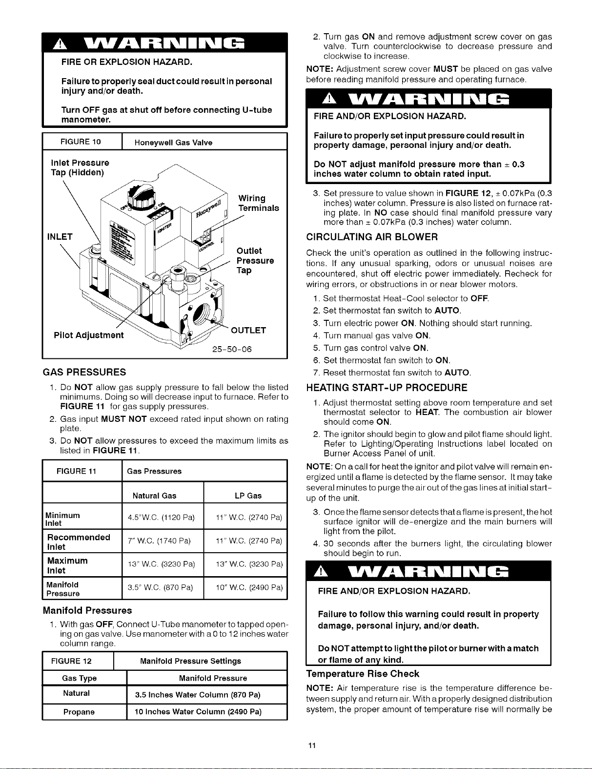
FIGURE 10 [ Honeywell Gas Valve
Inlet Pressure
Tap (Hidden)
Wiring
Terminals
INLET
Outlet
Pressure
Tap
Pilot Adjustment
25-50-06
GAS PRESSURES
1. Do NOT allow gas supply pressure to fall below the listed
minimums. Doing so will decrease input to furnace. Refer to
FIGURE 11 for gas supply pressures.
2. Gas input MUST NOT exceed rated input shown on rating
plate.
3. Do NOT allow pressures to exceed the maximum limits as
listed in FIGURE 11.
FIGURE 11 Gas Pressures
Natural Gas LP Gas
Minimum 4.5"W.C. (1120 Pa) 11" W.C. (2740 Pa)
Inlet
Recommended 7" W.C. (1740 Pa) 11" W.C. (2740 Pa)
Inlet
Maximum 13" W.C. (3230 Pa) 13" W.C. (3230 Pa)
Inlet
Manifold 3.5" W.C. (870 Pa) 10" W.C. (2490 Pa)
Pressure
Manifold Pressures
1. With gas OFF, Connect U-Tube manometer to tapped open-
ing on gas valve. Use manometer with a 0 to 12 inches water
column range.
FIGURE 12 Manifold Pressure Settings
Gas Type Manifold Pressure
Natural 3.5 Inches Water Column (870 Pa)
Propane 10 Inches Water Column (2490 Pa)
2. Turn gas ON and remove adjustment screw cover on gas
valve. Turn counterclockwise to decrease pressure and
clockwise to increase,
NOTE: Adjustment screw cover MUST be placed on gas valve
before reading manifold pressure and operating furnace.
FIRE AND/OR EXPLOSION HAZARD.
Failure to properly set input pressure could result in
property damage, personal injury and/or death.
Do NOT adjust manifold pressure more than _ 0.3
inches water column to obtain rated input.
3. Set pressure to value shown in FIGURE 12, _+0.07kPa (0.3
inches) water column. Pressure is also listed on furnace rat-
ing plate, in NO case should final manifold pressure vary
more than _+0.07kPa (0.3 inches) water column.
CIRCULATING AIR BLOWER
Check the unit's operation as outlined in the following instruc-
tions. If any unusual sparking, odors or unusual noises are
encountered, shut off electric power immediately. Recheck for
wiring errors, or obstructions in or near blower motors.
1. Set thermostat Heat-Cool selector to OFF.
2. Set thermostat fan switch to AUTO.
3. Turn electric power ON. Nothing should start running.
4. Turn manual gas valve ON.
5. Turn gas control valve ON.
6. Set thermostat fan switch to ON.
7. Reset thermostat fan switch to AUTO.
HEATING START-UP PROCEDURE
1. Adjust thermostat setting above room temperature and set
thermostat selector to HEAT. The combustion air blower
should come ON.
2. The ignitor should begin to glow and pilot flame should light.
Refer to Lighting/Operating instructions label located on
Burner Access Panel of unit.
NOTE: On a call for heat the ignitor and pilot valve will remain en-
ergized until a flame is detected by the flame sensor. It may take
several minutes to purge the air out of the gas lines at initial start-
up of the unit.
3. Once the flame sensor detects that a flame is present, the hot
surface ignitor will de-energize and the main burners wil!
light from the pilot.
4. 30 seconds after the burners light, the circulating blower
should begin to run.
FIRE AND/OR EXPLOSION HAZARD.
Failure to follow this warning could result in property
damage, personal injury, and/or death.
Do NOT attempt to light the pilot or burner with amatch
or flame of any kind.
Temperature Rise Check
NOTE: Air temperature rise is the temperature difference be-
tween supply and return air. With a properly designed distribution
system, the proper amount of temperature rise will normally be
Loading ...
Loading ...
Loading ...