Loading ...
Loading ...
Loading ...
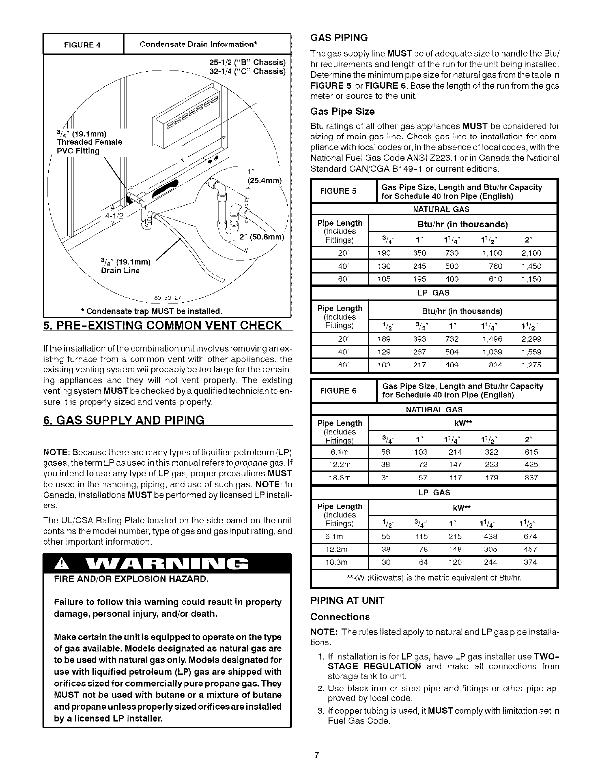
FIGURE 4 [ GAS PIPING
Condensate Drain Information*
25-1/2 ("B" Chassis)
32-1/4 ("C" Chassis)
3/4" (19.1mm)
Threaded Female
(25.4mm)
2" (50.8mm)
* Condensate trap MUST be installed,
5. PRE-EXISTING COMMON VENT CHECK
If the installation of the combination unit involves removing an ex-
isting furnace from a common vent with other appliances, the
existing venting system wil! probably be too large for the remain-
ing appliances and they will not vent properly. The existing
venting system MUST be checked by a qualified technician to en-
sure it is properly sized and vents properly.
6. GAS SUPPLY AND PIPING
NOTE: Because there are many types of liquified petroleum (LP)
gases, the term LP as used in this manual refers topropane gas. If
you intend to use any type of LP gas, proper precautions MUST
be used in the handling, piping, and use of such gas. NOTE: In
Canada, installations MUST be performed by licensed LP install-
ers.
The UL/CSA Rating Plate located on the side panel on the unit
contains the model number, type of gas and gas input rating, and
other important information.
FIRE AND/OR EXPLOSION HAZARD.
Failure to follow this warning could result in property
damage, personal injury, and/or death.
Make certain the unit is equipped to operate on the type
of gas available. Models designated as natural gas are
to be used with natural gas only. Models designated for
use with liquified petroleum (LP) gas are shipped with
orifices sized for commercially pure propane gas. They
MUST not be used with butane or a mixture of butane
and propane unless properly sized orifices are installed
by a licensed LP installer.
The gas supply line MUST be of adequate size to handle the Btu/
hr requirements and length of the run for the unit being installed.
Determine the minimum pipe size for natural gas from the table in
FIGURE 5 or FIGURE 6. Base the length of the run from the gas
meter or source to the unit.
Gas Pipe Size
Btu ratings of all other gas appliances MUST be considered for
sizing of main gas line. Check gas line to installation for com-
pliance with local codes or, in the absence of local codes, with the
National Fuel Gas Code ANSI Z223.1 or in Canada the National
Standard CAN/CGA B149-1 or current editions.
FIGURE 5 Gas Pipe Size, Length and Btu/hr Capacity
for Schedule 40 Iron Pipe (English)
NATURAL GAS
Pipe Length
(Includes
Fittings)
20'
Btu/hr (in thousands)
3/4" 1" 11/4" 11/2" 2"
190 350 730 1,100 2,100
40' 130 245 500 760 1,450
60' 105 195 400 610 1,150
LP GAS
Pipe Length Btu/hr (in thousands)
(Includes
Fittings) 1/2" 3/4" 1" 11/4" 11/2"
20' 189 393 732 1,496 2,299
40' 129 267 504 1,039 1,559
60' 103 217 409 834 1,275
Gas Pipe Size, Length and Btu/hr Capacity
FIGURE 6 for Schedule 40 Iron Pipe (English)
NATURAL GAS
Pipe Length kW**
(includes
Fittin,qs) 3/4" 1" 11/4" 11/2" 2"
6.1m 56 103 214 322 615
12.2m 38 72 147 223 425
18.3m 31 57 117 179 337
LP GAS
Pipe Length kW**
(includes
Fittings) 1/2" 3/4" 1" 11/4" 11/2"
6.1m 55 115 215 438 674
12.2m 38 78 148 305 457
18.3m 30 64 120 244 374
**kW (Kilowatts) is the metric equivalent of Btu/hr.
PIPING AT UNIT
Connections
NOTE: The rules listed apply to natural and LP gas pipe installa-
tions.
1. Ifinstallation is for LP gas, have LP gas installer use TWO-
STAGE REGULATION and make all connections from
storage tank to unit.
2. Use black iron or steel pipe and fittings or other pipe ap-
proved by local code.
3. Ifcopper tubing is used, it MUST comply with limitation set in
Fue! Gas Code.
Loading ...
Loading ...
Loading ...