Loading ...
Loading ...
Loading ...
8. DUCTWORK
Maximum recommended velocity in trunk ducts is 1000 feet per
minute. Velocity in branches should not exceed 800 feet per min-
ute.
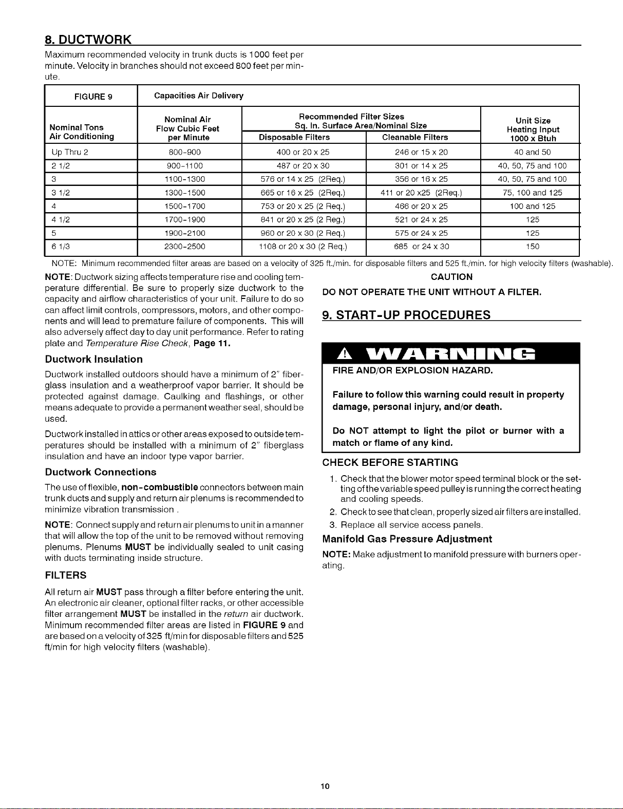
FIGURE 9 Capacities Air Delivery
Nominal Tons
Air Conditioning
Up Thru 2
2 1/2
3
3 1/2
4
4 1/2
5
6 1/3
Nominal Air
Flow Cubic Feet
per Minute
800-900
900-1100
1100-1300
1300-1500
1500-1700
1700-1900
1900-2100
2300-2500
Recommended Filter Sizes
Sq. In. Surface Area/Nominal Size
Disposable Filters Cleanable Filters
400 or 20 x 25 246 or 15 x 20
487 or 20 x 30 301 or 14 x 25
576 or 14x25 (2Req.) 356 or 16x25
665 or 16 x 25 (2Req.) 411 or 20 x25 (2Req.)
753 or 20 x 25 (2 Req.) 466 or 20 x 25
841 or 20 x 25 (2 Reg.) 521 or 24 x 25
960 or 20 x 30 (2 Req.) 575 or 24 x 25
1108 or 20 x 30 (2 Req.) 685 or 24 x 30
Unit Size
Heating Input
1000 x Btuh
40 and 50
40, 50, 75 and 100
40, 50, 75 and 100
75, 100 and 125
100 and 125
125
125
150
NOTE: Minimum recommended filter areas are based on a velocity of 325 ft./min, for disposable filters and 525ft./min, for high velocity filters (washable).
NOTE: Ductwork sizing affects temperature rise and cooling tem- CAUTION
perature differential. Be sure to properly size ductwork to the DO NOT OPERATE THE UNIT WITHOUT A FILTER,
capacity and airflow characteristics of your unit. Failure to do so
can affect limit controls, compressors, motors, and other compo- 9, START-UP PROCEDURES
nents and will lead to premature failure of components. This will
also adversely affect day to day unit performance. Refer to rating
plate and Temperature Rise Check, Page 11.
Ductwork Insulation
Ductwork installed outdoors should have a minimum of 2" fiber-
glass insulation and a weatherproof vapor barrier. It should be
protected against damage. Caulking and flashings, or other
means adequate to provide a permanent weather seal, should be
used.
Ductwork installed in attics or other areas exposed to outside tem-
peratures should be installed with a minimum of 2" fiberglass
insulation and have an indoor type vapor barrier.
Ductwork Connections
The use of flexible, non-combustible connectors between main
trunk ducts and supply and return air plenums is recommended to
minimize vibration transmission.
NOTE: Connect supply and return air plenums to unit in a manner
that will allow the top of the unit to be removed without removing
plenums. Plenums MUST be individually sealed to unit casing
with ducts terminating inside structure.
FILTERS
FIRE AND/OR EXPLOSION HAZARD.
Failure to follow this warning could result in property
damage, personal injury, and/or death.
Do NOT attempt to light the pilot or burner with a
match or flame of any kind.
CHECK BEFORE STARTING
1. Check that the blower motor speed terminal block or the set-
ting ofthevariable speed pulley isrunning the correct heating
and cooling speeds.
2. Checktoseethatclean, properlysizedairfiltersareinstalled.
3. Replace all service access panels.
Manifold Gas Pressure Adjustment
NOTE: Make adjustment to manifold pressure with burners oper-
ating,
All return air MUST pass through a filter before entering the unit.
An electronic air cleaner, optional filter racks, or other accessible
filter arrangement MUST be installed in the return air ductwork.
Minimum recommended filter areas are listed in FIGURE 9 and
are based on a velocity of 325 ff/min for disposable filters and 525
ft/min for high velocity filters (washable).
10
Loading ...
Loading ...
Loading ...