Loading ...
Loading ...
Loading ...
obtained when the unit is operating at rated input with the recom-
mended blower speed.
1. The temperature rise must be within the specifications
marked on the unit rating plate.
To check the temperature rise through the unit, place ther-
mometers in the supply and return air ducts as close to the
unit as possible.
Open ALL registers and duct dampers. Operate unit AT
LEAST 15 minutes before taking readings.
Ifthe correct amount of temperature rise is not obtained when op-
erating on the recommended blower speed, it may be necessary
to change the blower speed. A faster blower speed will decrease
the temperature rise. A slower blower speed wil! increase the tem-
perature rise.
NOTE; The blower speed MUST be set to give the correct air tem-
perature rise through the furnace as marked on the rating plate.
See FIGURE 14 for more information.
2. After 15 minutes of operation check the limit control function
by blocking the
return air grille(s).
After several minutes the main burners and pilot should go
OFE The circulating air blower should continue to run.
Remove air restrictions. Pilot and main burners should
relight after a cool down period of a few minutes.
3. Adjust the thermostat setting below room temperature.
Pilot and main burners and combustion air blower should go
OFE
The circulating air blower should continue to run for 60, 100,
140 or 180 seconds. This time isadjustable. See Figure 14
for more information.
4. Set thermostat Heat-Cool selector to OFF
FAN CONTROL CHECK
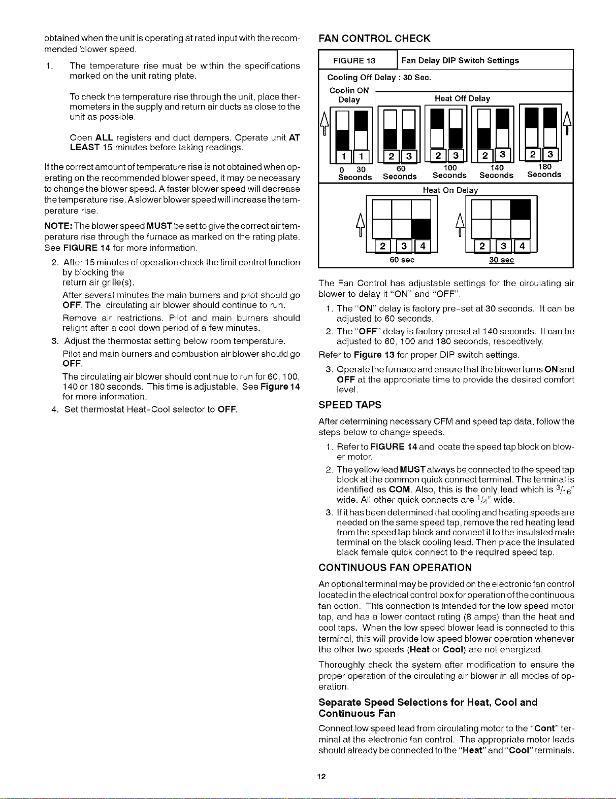
FIGURE 13 J Fan Delay DIP Switch Settings
Cooling Off Delay : 30 Sec.
Coolin ON
Delay Heat Off Delay
0 30
Seconds
60 100 140
Seconds Seconds Seconds
180
Seconds
Heat On Delay
MMM DDbJ
60 sec 30 sec
The Fan Control has adjustable settings for the circulating air
blower to delay it "ON" and "OFF".
1. The "ON" delay is factory pre-set at 30 seconds. It can be
adjusted to 60 seconds.
2. The "OFF" delay is factory preset at 140 seconds. It can be
adjusted to 60, 100 and 180 seconds, respectively.
Refer to Figure 13 for proper DIP switch settings.
3. Operate the furnace and ensure that the blower turns ON and
OFF at the appropriate time to provide the desired comfort
level.
SPEED TAPS
After determining necessary CFM and speed tap data, follow the
steps below to change speeds.
1. Refer to FIGURE 14 and locate the speed tap block on blow-
er motor.
2. The yellow lead MUST always be connected to the speed tap
block at the common quick connect terminal. The terminal is
identified as COM. Also, this is the only lead which is 3/16"
wide. All other quick connects are 1/4" wide.
3. If it has been determined that cooling and heating speeds are
needed on the same speed tap, remove the red heating lead
from the speed tap block and connect it to the insulated male
terminal on the black cooling lead. Then place the insulated
black female quick connect to the required speed tap.
CONTINUOUS FAN OPERATION
An optional terminal may be provided on the electronic fan control
located in the electrical control box for operation ofthe continuous
fan option. This connection is intended for the low speed motor
tap, and has a lower contact rating (8 amps) than the heat and
cool taps. When the low speed blower lead is connected to this
terminal, this will provide low speed blower operation whenever
the other two speeds (Neat or Cool) are not energized.
Thoroughly check the system after modification to ensure the
proper operation of the circulating air blower in all modes of op-
eration.
Separate Speed Selections for Heat, Cool and
Continuous Fan
Connect low speed lead from circulating motor to the "Cont" ter-
minal at the electronic fan control. The appropriate motor leads
should already be connected to the "Heat" and "Cool" terminals.
12
Loading ...
Loading ...
Loading ...