
Loading ...
Loading ...
Loading ...
18
SECURING THE PATIO MOUNT GRILL
Important: BEFORE USE, the patio mount base
must be securely fastened to a stable,
level surface to ensure the grill remains
fixed and upright at all times.
Locate the patio mount base in the planned grill
location and mark the 4 holes. Drill the marked holes
to a
1
/
2
" diameter x 1
1
/
2
" depth. Insert the lag shields
(see PARTS LIST) into the holes, being sure that they
are flush with the ground.
Align the holes on the patio mount base over the lag
shields in the ground. Secure the base with the lag
screws (see PARTS LIST) using a
7
/
16
" nut driver.
CONNECT THE GAS SUPPLY
For household propane or natural gas units:
1. Route the flex connector to the gas supply stub.
2. Turn OFF the gas supply at the source.
3. A shut-off valve is required within 6 feet of the unit.
If shut-off valve is installed in-line:
• Install the supplied flare-to-NPT adapter to the gas
supply (NPT) using a pipe joint compound resistant to
all gasses (see Fig. 18-2, A). Tighten securely.
• Connect the flex connector to the adapter (see Fig.
18-2, A). Tighten securely.
If shut-off valve is connected to end of gas supply stub:
• Connect the flex connector to the shut-off valve (flare)
(see Fig. 18-2, B). Tighten securely.
For propane cylinders:
For connecting a propane unit to a portable propane tank,
read the safety warnings and follow the instructions in the
section SAFE USE AND MAINTENANCE OF PROPANE GAS
CYLINDERS.
Important: An appropriate adapter will be required to connect
the existing flex connector to an L.P. regulator/
hose assembly.
LEAK TEST
Turn all burner control knobs to the OFF position. Turn the gas
supply on. Then carefully check all gas connections for leaks
with a brush and half-soap/half-water solution before lighting.
NEVER USE A MATCH OR OPEN FLAME TO TEST FOR
LEAKS.
RECONNECT POWER SUPPLY WIRES
CAUTION: IMPROPERLY CONNECTED WIRES WILL
CAUSE DAMAGE TO THE GRILL AND MAY
RESULT IN PROPERTY DAMAGE AND/OR
PERSONAL INJURY.
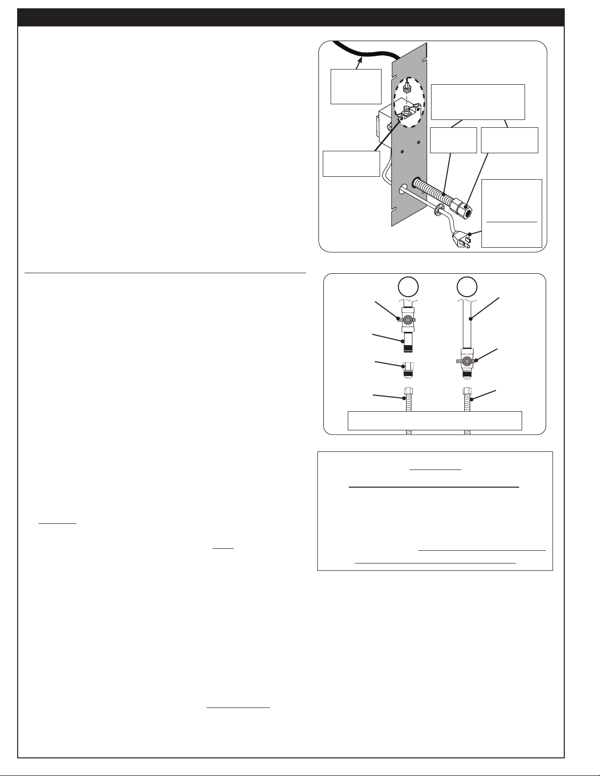
To connect the power supply, connect the converter harness to
the power supply as shown in Fig. 18-1.
Important: Apply dielectric grease to the male connectors prior
to making any wire connections.
RE-SECURE ACCESS PLATE
Carefully replace the access plate using the four screws,
ensuring all interior components are properly oriented inside
of the grill. Ensure the power supply cord (and flex connector
if applicable) coming out of the rear of the post are properly
situated and the plastic bushing/grommet pieces are secure
in place.
CONNECT POWER CORD
Connect the cord coming from the rear access plate to a
120VAC (15 AMP minimum) GFCI GROUNDED 3-wire
receptacle. The GFCI receptacle must be a WEATHER-
PROOF IN-USE COVERED RECEPTACLE.
PATIO MOUNT INSTALLATION
(Cont.)
Fig. 18-1 Connect: Gas, Wires, Plate, Power
WARNING
Electrical Grounding Instructions:
This appliance is equipped with a three-
pronged (grounding) plug for your protection
against shock hazard and should be plugged
directly into a properly grounded three-
prong receptacle. Do not cut or remove the
grounding prong from this plug.
Flare-to-NPT
adapter
Flex
connector
To gas supply
(as applicable, flex
location may vary)
To 120VAC
(15 AMP min.)
GFCI
GROUNDED
3-wire
receptacle
Wire
Connections
AC/DC
converter
harness
Fig. 18-2 Connecting to a gas line
Gas supply
(NPT)
Flex
connector
(from grill)
Flare-to-NPT
shut-off valve*
(end of gas
supply)
NPT-to-NPT
shut-off valve*
(in-line)
Gas supply
(NPT)
Flare-to-NPT
adapter
Flex
connector
(from grill)
* Shut-off valve: required, not included, must
be within 6 feet of unit
A B
-OR-
Loading ...
Loading ...
Loading ...