Loading ...
Loading ...
Loading ...
10
The control panel MUST remain removable for servicing (see
CONTROL PANEL REMOVAL section).
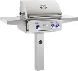
COMBUSTION AIR AND COOLING AIRFLOW
Proper airflow (front-to-back, Fig. 10-) MUST be maintained
for the unit to perform as it was designed. If airflow is blocked,
overheating and poor combustion will result. Do not block the
1" front air inlet along the bottom of the control panel.
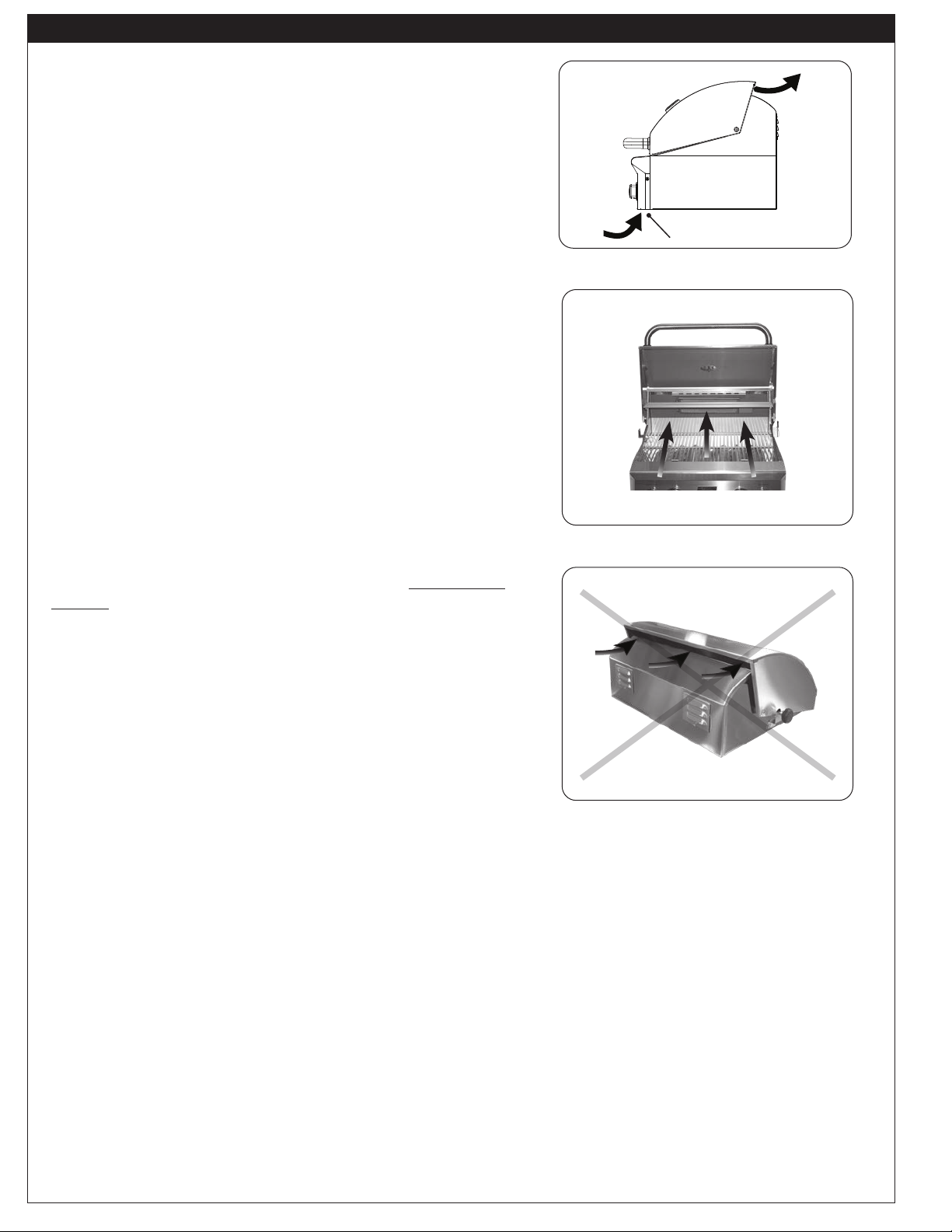
CAUTION: Wind blowing into or across the rear oven lid
vent (Fig. 10-) can cause poor performance
and/or dangerous overheating. Install the grill
so that the prevailing wind blows toward the
front of the grill (Fig. 10-). A wind deflector is
available for purchase to assist in proper
airflow during windy conditions. See Table
1 for model numbers. Follow the instructions
included with the wind deflector for installation.
GAS-SUPPLY PLUMBING REQUIREMENTS
For natural gas or a household propane system, rigid
1
/
2
" or
3
/
4
" black steel pipe or local code-approved pipe is required
to conduct the gas supply to the unit. Contact your local gas
supplier. Connect this pipe to the C.S.A.-approved quick
connect hose (attached). Apply only joint compounds that are
resistant to all gasses on all NPT pipe fittings except flare
fittings. Make sure to tighten all fittings securely.
Note: If
1
/
2
" pipe is used with natural gas, it should be
no longer than 20'.
Important: A shut-off valve (not included) in the gas
line is required. It provides for safety when
the unit is not in use and for convenient
maintenance and repair. It must be installed
within 6 feet of the unit and must be easily
accessible. Use a pipe joint compound
resistant to all gasses on all male fittings
except flare fittings.
GAS SUPPLY AND MANIFOLD PRESSURES:
For natural gas - normal 7" water column (w.c.), minimum
5", maximum 10
1
/
2
". For propane gas - normal 11" w.c.,
minimum 10", maximum 13".
INSTALLATION REQUIREMENTS (Cont.)
CORRECT
PLACE GRILL SO PREVAILING WIND
BLOWS TOWARD FRONT OF GRILL
Fig. 10-2 Airflow direction - CORRECT
Fig. 10-1 Airflow diagram
YOU MUST PROTECT REAR OVEN VENT FROM
PREVAILING WIND
Rear oven lid vent
INCORRECT
Fig. 10-3 Airflow direction - INCORRECT
(1" front air inlet)
Loading ...
Loading ...
Loading ...