Loading ...
Loading ...
Loading ...
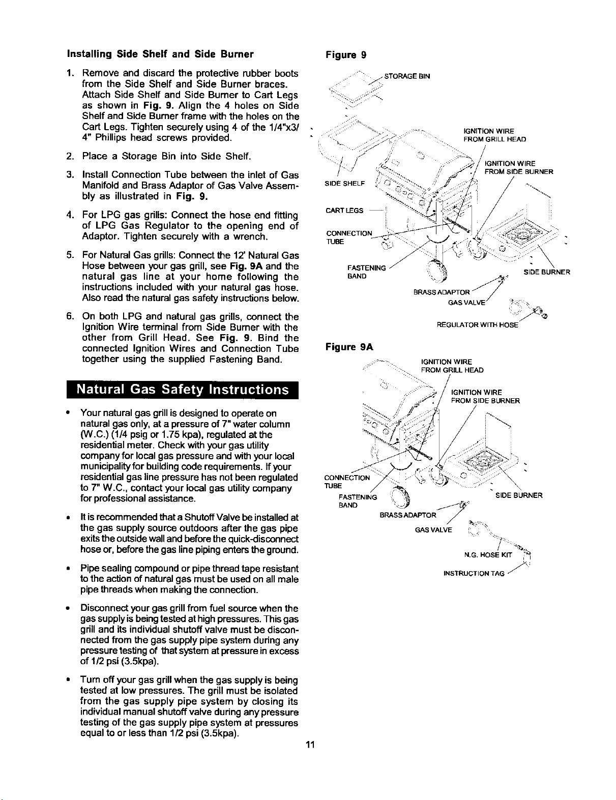
InstallingSideShelf and Side Burner
1. Remove and discard the protective rubber boots
from the Side Shelf and Side Burner braces.
Attach Side Shelf and Side Burner to Cart Legs
as shown in Fig. 9. Align the 4 holes on Side
Shelf and Side Burnerframe with the holes on the
Cart Legs. Tighten securely using4 of the 1/4"x3/
4" Phillips head screws provided.
2. Place a Storage Bin into Side Shelf.
3. Install Connection Tube between the inlet of Gas
Manifoldand BrassAdaptor of Gas Valve Assem-
bly as illustrated in Fig. 9.
4. For LPG gas grills: Connect the hose end fitting
of LPG Gas Regulator to the opening end of
Adaptor. Tighten securely with a wrench.
5. For Natural Gas grills:Connect the 12' NaturalGas
Hose between your gas grill, see Fig. 9A and the
natural gas line at your home following the
instructionsincluded with your natural gas hose.
Also read the natural gas safety instructionsbelow.
6. On both LPG and natural gas grills, connect the
IgnitionWire terminal from Side Burner with the
other from Grill Head. See Fig. 9. Bind the
connected Ignition Wires and Connection Tube
together using the supplied Fastening Band.
Your natural gas grillisdesignedto operateon
naturalgasonly, at a pressure of 7"water column
(W.C.) (1/4 psig or 1.75 kpa), regulated at the
residential meter. Check with your gas utility
company for local gas pressure and with your local
municipality for building code requirements. If your
residential gas line pressure has not been regulated
to 7" W.C., contact your local gas utility company
for professional assistance.
Itisrecommendedthat a ShutoffValvebe installedat
the gas supplysource outdoors after the gas pipe
exitsthe outsidewalland beforethequick-disconnect
hoseor,beforethe gaslinepipingentersthe ground.
Pipe sealingcompound or pipe thread tape resistant
tothe actionof naturalgas mustbe usedon allmale
pipethreads when makingtheconnection.
Disconnectyour gas grillfrom fuel sourcewhen the
gassupply is beingtestedat highpressures. This gas
gdll and its individual shutoff valve must be discon-
nected from the gas supply pipe system during any
pressure testing of that system at pressure in excess
of 1/2psi (3.5kpa).
Turn offyourgas grillwhen the gas supplyis being
tested at low pressures. The grillmust be isolated
from the gas supply pipe system by closing its
individualmanualshutoffvalve duringanypressure
testingof the gas supply pipesystem at pressures
equalto or lessthan 1/2 psi (3.5kpa).
Figure 9
STORAGE BIN
S"
4 .
" 1::: IGNITION WIRE
= :. ." :'_ : FROM GRILL HEAD
- i_Y . .
,J
GNITION WIRE
FROM SIDE BURNER
SIDE SHELF / _..
CART LEGS --
CONNECTION
TUBE --_%:
FASTENING
BAND
SIDE BURNER
BRASS ADAPTOR _'_ ;_
GAS VALVE / _'_ a
REGULATOR WITH HOSE
Figure 9A
IGNITION WIRE
::.. FROM GRILL HEAD
:::.
FROM SIDE BURNER
CONNECTION
TUBE
FASTENING
BAND
:; •'_ SIDE BURNER
BRASS ADAPTOR /
GAS VALVE
N.G. HOSE KIT ,_
INSTRUCTION TAG J_
11
Loading ...
Loading ...
Loading ...