Loading ...
Loading ...
Loading ...
INSTALLATION
Residen al Hybrid Electric Heat Pump Water Heater Use and Care Guide • 19
INSTALLATION
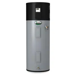
Figure 29 - User Interface Module (UIM) Display
xxxxx
xxxxx
xxxxx
xxxxx
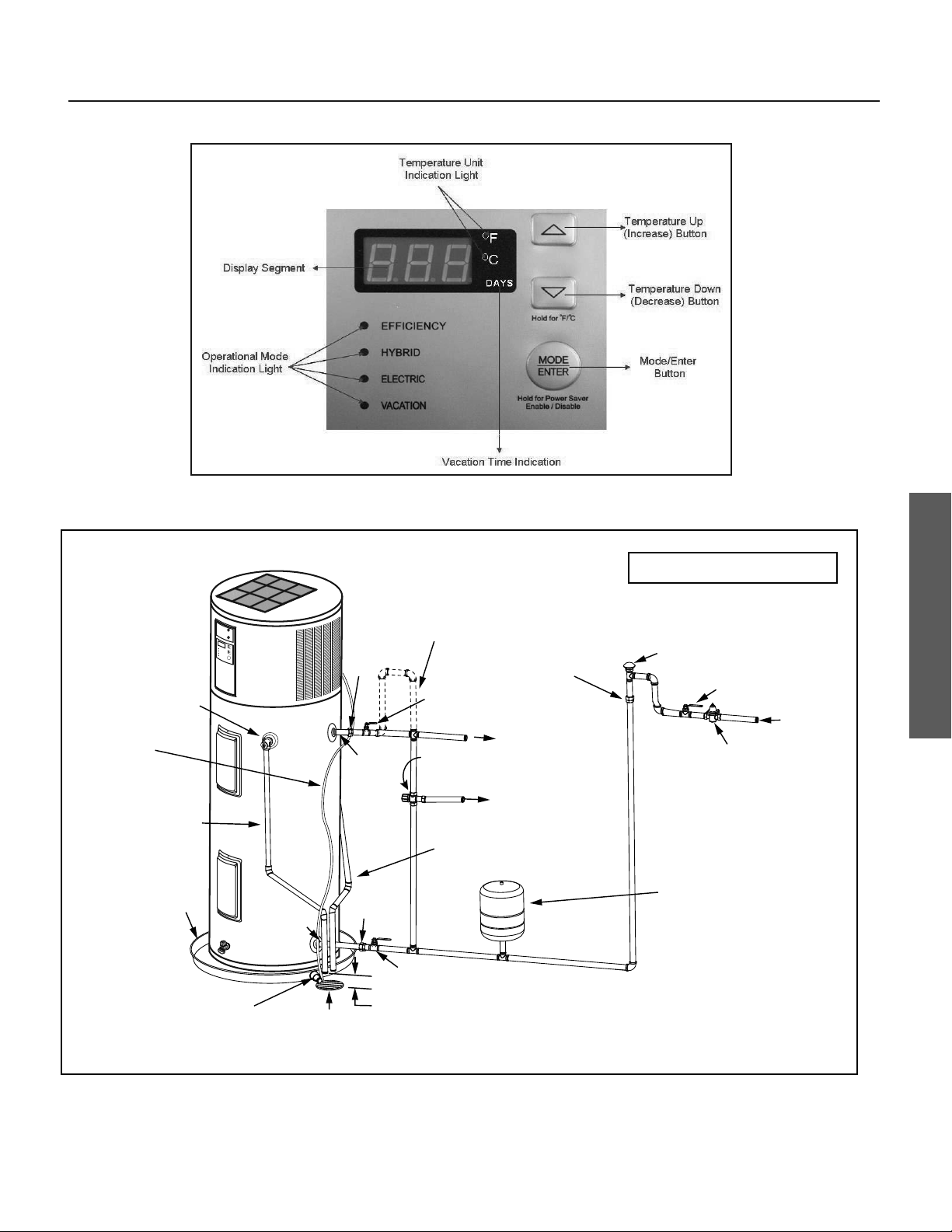
Vacuum Relief Valve
(when required by local code)
Cold Water
Inlet Valve
Massachusetts: Install a vacuum relief in
cold water line per section 19 MGL 142.
Cold Water
Inlet
Pressure Reducing Valve (PRV)
should be installed where the water
supply enters the residence.
When installed PRVs create a
closed water system, a thermal
expansion tank must be installed.
* If an adequate drain is not available for the condensate drain lines then a condensate pump must be used. DO NOT discharge the condensate drain
lines into the metal drain pan.
In a closed system, use a
thermal expansion tank.
See “Closed System/
Thermal Expansion”
section.
6” Maximum
Air Gap
Shut-off Valve
(Cold)
*Primary Condensate Drain (3/4” PVC)
Tempered Water to Fixtures
Optional Mixing Valve - Follow the Mixing
Valve’s Manufacturer’s Installation
Instructions. (Set to 120°F / 48.8°C)
Untempered Water Outlet
Shut-off Valve (Hot)
Union
Drain Line 1”
ID Minimum
Drain Pan 2 1/2”
Depth Maximum and
2 Inches wider than
the water heater.
Discharge Pipe
(Do Not Cap or Plug)
Temperature and
Pressure Relief Valve
Union
Drain
Cold
(Inlet)
Hot
(Outlet)
Optional Heat Trap Piping
1/2” Flexible
Secondary
Condensate
Tubing
Union
Figure 30 - Completed Water System Piping
Loading ...
Loading ...
Loading ...