Loading ...
Loading ...
Loading ...
INSTALLATION
Residen al Hybrid Electric Heat Pump Water Heater Use and Care Guide • 11
Step 4:
Installing the new
water heater
1
Completely read all instruc-
ons before beginning. If you
are not sure you can complete
the installa on, DO NOT RETURN THIS
UNIT TO THE STORE. Seek assistance
from any of the following sources:
• Schedule an appointment with
a qualified person to install your
water heater.
• Call our Technical Assistance Hotline
at 1-800-527-1953
2
Install a suitable drain pan
that is piped to an adequate
drain.
3
Set the water heater in place
taking care not to damage the
drain pan.
NOTICE: Most codes require se ng
the water heater in a suitable drain
pan piped to an adequate drain. The
drain pan helps avoid property damage
which may occur from condensa on
or leaks in the piping connec ons or
tank. The drain pan must be at least
two inches wider than the diameter
of the water heater. Install the drain
pan so the water level is limited to a
maximum depth of 1-3/4”.
4
Verify that the water heater is
set in place properly. Check
that:
• The T&P Relief Valve will not be in
contact with any electrical parts.
• There is adequate space to install
the T&P Relief Valve discharge pipe
and that it can be piped to a sepa-
rate drain (and not into the drain
pan).
• There is adequate space to install
proper condensate drain piping.
• There is adequate access and space
around the water heater for future
maintenance. A minimum clearance
of 6 inches must be maintained
from all sides and 6 inches from the
top for access to the air filter.
• Unit is level to allow proper con-
densate drainage. An unlevel unit
may lead to condensate draining
inproperly and resulting in property
damage.
DO NOT CONNECT ELECTRICAL
WIRING UNTIL YOU ARE
INSTRUCTED TO DO SO.
NOTICE: Connec ng electrical power
to the tank before it is completely
full of water (water must run FULL
STREAM from a hot water tap for a full
three minutes) will cause the upper
hea ng element to burn out.
Step 5:
Connec ng the Conden-
sate Pump When Re-
quired
NOTE: If no fl oor drain is available or
the drain is above the level of the
condensate line, a condensate pump
must be installed.
1
Follow condensate drain
pump manufacturers instruc-
ons for installa on.
Connec ng the Conden-
sate Pump Op onal
Overfl ow Shut Off
Switch
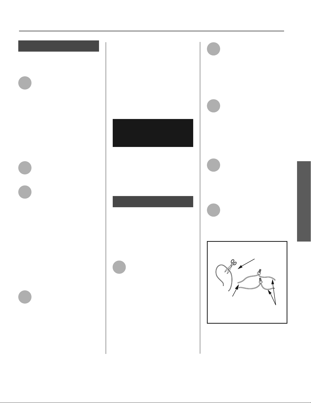
1
Locate the white 22 AWG wire
loop inside the condensate
drain access compartment by
removing the 4 screws a aching the
condensate drain access cover to the
unit. Cut the loop and strip insula on
off the 2 ends (Figures 14 & 15 on page
11).
2
Measure the distance from
the condensate drain access
cover to the condensate
pump, and cut two 22 AWG wires to
correct length and strip the insula on
at both ends. Thread both ends
through the grommet on the drain pan
cover.
3
Connect these 2 wires to the
2 wires on the water heater
using wire nuts or other con-
nectors. Reinstall the condensate drain
access cover and keep the connec on
joints inside of the cover.
4
Connect the free ends of the
2 wires to the shut off switch
on the condensate pump in
accordance with the condensate pump
manufacturers recommenda ons.
Condensate Pump Wiring Loop
22 AWG - White
(Loop Located Close to the Drain Connections)
White Wires
From Water Heater
Wires to Condensate
Pump Overflow
Shut Off Switch
(22 AWG or Larger)
Figure 14 - Wiring Loop for connec on of
Condensate Pump.
INSTALLATION
Loading ...
Loading ...
Loading ...