Loading ...
Loading ...
Loading ...
INSTALLATION
Residen al Hybrid Electric Heat Pump Water Heater Use and Care Guide • 15
INSTALLATION
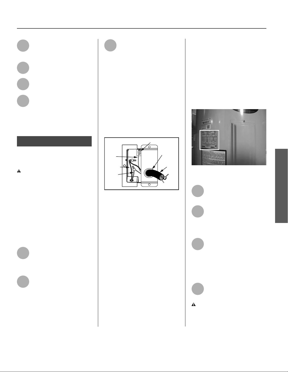
Power Supply
Connector
Black Wire
Red Wire
Green
Ground
Wire
1/2” Conduit
Opening
Green Ground Screw
3
Open a hot water faucet and
allow the water to run un l it
fl ows with a full stream.
4
Let the water run full stream
for three full minutes.
5
Close the hot water faucet and
replace the aerator.
6
Check inlet and outlet connec-
ons and water pipes for leaks.
Dry all pipes so that any drips
or leaks will be apparent. Repair any
leaks. Almost all leaks occur at connec-
ons and are not a tank leak.
Step 11:
Make electrical
connec ons
WARNING! Working on an ener-
gized circuit can result in severe injury
or death from electrical shock.
NOTICE: Do not turn electrical power
on unless you are sure all of the air is
out of the tank and the tank is com-
pletely full of water. Although this water
heater is equipped with “Dry Fire” pro-
tec on, be certain all air is purged from
the tank before making any electrical
connec ons.
1
Be sure the electrical power to
the water heater is turned OFF
at the circuit breaker panel (or
remove the circuit’s fuses).
2
Using a non-contact circuit
tester, check the wiring to make
certain the power is OFF.
3
This water heater requires a
240/208 VAC single phase 30
amp power supply, at 60Hz.
Check the water heater’s data plate
(see fi gure 23 on page 15) and ensure
that the home’s voltage, wiring size
(ampacity) and circuit breaker ra ng
and type are correct for this water
heater. Refer to the wiring diagram
located on the water heater for the
correct electrical connec ons. Ensure
that wire sizes, type, and connec ons
comply with all applicable local codes.
In the absence of local codes, follow
NFPA-70 and the current edi on of the
Na onal Electric Code (NEC).
Figure 22 - Connecting the electrical wires.
If metal conduit is used for the ground-
ing conductor:
• The grounding electrode conductor
shall be of copper, aluminum, or
copperclad aluminum. The material
shall be of one con nuous length
without a splice or joint.
• Rigid metal conduit, intermediate
metal conduit, or electrical metallic
tubing may be used for the ground-
ing means if conduit or tubing is
terminated in fi ngs approved for
grounding.
• Flexible metal conduit or fl exible
metallic tubing shall be permi ed
for grounding if all the following
condi ons are met:
A. The length in any ground return path
does not exceed 6 feet.
B. The circuit conductors contained
therein are protected by overcurrent
devices rated at 30 amperes.
C. The conduit or tubing is terminated
in fi ngs approved for grounding.
For complete grounding details and
all allowable excep ons, refer to the
current edi on of the Na onal Electric
Code NFPA 70.
Figure 23 - The water heater’s electrical
requirements can be determined from the
data plate.
4
Remove the cover on the
electrical junc on box on the
side of the water heater.
5
Install wiring in an approved
conduit (if required by local
codes). Use a UL listed or CSA
approved strain relief to secure the
electrical wiring to the water heater.
6
Connect the ground wire to
the green ground screw.
Connect the home’s two
power wires to the water heater’s two
power wires. Use suitable wire nuts or
other approved means to make the
power connec ons.
7
Replace the junc on box cover
and secure with the screw
provided.
WARNING! Be sure cover is secured
to reduce the risk of fi re and electric
shock.
Loading ...
Loading ...
Loading ...